1
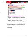
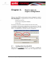
ARES
Aprilia Racing Engine Setup
Program
User’s Guide
Version 1.4
Index
CH AP T E R 1 . INTRODUCTION .............................................................................................. 4
1.1.
NOMENCLATURE LIST ................................................................................................... 5
1.2.
PRINCIPAL ARES SCREEN............................................................................................ 6
CH AP T ER 2 . HOW TO OPEN AN ENGINE CONFIGURATION ....................................... 8
2. 1.
CONFIGURATION FROM THE ECU ................................................................................. 8
CH AP T ER 3 . HOW TO MODIFY A CONFIGURATION .................................................... 11
3. 1.
OPERATION LOG.......................................................................................................... 12
3. 2.
CURVES ....................................................................................................................... 13
3. 2. A.
3. 2. B.
3. 2. C.
3. 2. D.
1.
2.
display the complete table in a graph:
display selected cells in a graph:
3. 2. E.
1.
2.
Add and Manage curves
Groups
Table Map
Graph
Modifying values
Modify map values in the table mode
Modify map values in the graph mode
13
14
15
16
16
17
20
20
23
3. 3.
PARAMETERS (PARAMETRI) ........................................................................................ 26
3. 4.
TUNING ADJUSTMENTS (REGOLAZIONI) ...................................................................... 26
CH AP T ER 4 . SAVING THE NEW CONFIGURATION....................................................... 28
4. 1.
SAVE CONFIGURATION TO DATABASE......................................................................... 28
4. 1. A.
Sections of the “Set configuration names” window
29
4. 1. B.
How to save the configuration
30
4. 2.
EXPORT CONFIGURATION TO FILE ............................................................................... 30
CH AP T ER 5 . FUNCTIONS WHEN ECU AND PC ARE CONNECTED .......................... 31
5. 1.
RECEIVE ....................................................................................................................... 31
5. 2.
TRANSMIT .................................................................................................................... 32
5. 2. A.
Tx configuration
33
5. 2. B.
Choose configuration to tx
33
5. 3.
TUNING MONITOR ......................................................................................................... 34
5. 3. A.
Gas tuning
34
5. 3. B.
Throttle valves, Air trumpet valves, Exhaust valves tuning.
35
5. 4.
SHOW DEVICE INFO...................................................................................................... 37
5. 5.
SHOW ERRORS ............................................................................................................ 37
5. 6.
SHOW CALIBRATION .................................................................................................... 37
CH AP T ER 6 . TOOLBAR FUNCTIONS ................................................................................ 41
6. 1.
COMPARE .................................................................................................................... 41
6. 2.
FW PORTING ................................................................................................................ 42
6. 3.
IMPORT DATA ............................................................................................................... 43
6. 4.
TUNING MONITOR ......................................................................................................... 44
6. 5.
SHOW DEVICE INFO...................................................................................................... 44
6. 6.
SHOW ERRORS ............................................................................................................ 45
6. 7.
RX CONFIGURATION AND TX CONFIGURATION ............................................................ 45
6. 8.
CHOOSE CURVE AND TX .............................................................................................. 45
6. 9.
OPTIONS ...................................................................................................................... 45
6. 9. A.
6. 9. B.
6. 9. C.
6. 9. D.
APENDIX A
Transmission
Correction
Miscellaneous
Database
46
46
47
48
TOOLBAR ICONS .......................................................................................... 49
Chapter 1.
Introduction
ARES, Aprilia Racing Engine Setup is a software developed by Aprilia
Racing S.r.l. in order to control and administer the Aprilia Engine Control
Unit (ECU).
All the parameters and adjustments required by the ECU to control the
engine (and vehicle) are called “Engine Configuration”, or simply
‘Configuration’.
Therefore ARES allows the user to change the ECU’s configuration in
order to optimize several engine and vehicle functions such as the
traction control strategy, ride by wire mapping, suspension calibration,
etc.
IMPORTANT FOR ETHERNET DOWNLOAD MODE:
In order to configure the Ethernet communication between APX2 and PC
it is necessary to configure the internet protocol.
For Windows XP:
1. Right-click My Network Places, and then click Properties.
2. Right-click the network connection for your network adapter, and then
click Properties.
3. On the General tab, click Internet Protocol (TCP/IP), and then click
Properties.
4. Click Use the following IP address, and then type the next values
only in the IP address, and Subnet mask, boxes.
IP address: 10.1.xxx.xxx
where xxx are free numbers, but it is necessary to write numbers.
Next IP address are not allow:
10.1.116.xxx
10.1.118.xxx
Subnet mask: 255.255.0.0
For Windows 7:
1. Click START button and then All control Panel Items.
2. Click on Network and Sharing Centre.
3. Then click on the option Connections: Local Area Connection.
4. Click on Properties.
5. Go to point 3 of Windows XP section.
Introduction
4
1.1.
Nomenclature List
Important terms must be defined in order to understand the following
document:
Curves: group of maps that allow to modify different parameters of the
engine like ignition, injection… These parameters are showed in tables.
Parameters: group of internal parameters to set the starting point of the
engine. Only for staff Aprilia.
Tuning Adjustments: group of characteristics of the engine (and some
of the chassis) that can be modify and set by the user.
A configuration includes all the previous characteristics (curves,
parameters and adjustments). The configuration is transmitted to the
ECU for a proper operation of motorbike in general and particularly of the
engine.
Depending on the firmware of the configuration there are different
parameters and tuning adjustments to modify.
In order to know more about available parameters and tuning
adjustments go to the document: ARES Engine Configuration Setup,
User’s guide and its corresponding Engine Configuration Version .
Introduction
5
1.2.
Principal ARES screen
HEADER
BAR
CONFIGURATION
INFORMATION
OPERATION
LOG
1. Header Bar
On the top of the screen is placed the header bar with the Main menu
and the toolbar.
2. Configuration Information
This part of the screen shows information about the opened
configurations.
Introduction
6
Configuration Name
Curve Groups
Look Up a
parameter
Configuration
Structure
A. Configuration name: It shows the name of the configuration. There
is as many tab as open configuration. Each tab contain the
configuration name.
B. Curve Groups: Shows the created curve groups.
C. Look up a parameter: to look up a parameter, curve, tuning
adjustment or value by writing the name in the text box.
D. Configuration structure: Shows the tree structure of the opened
configuration.
3. Editable window
All parameters, tuning adjustments and curve values are modified
within this window. By selecting the configuration variable that is to be
modified the appropriate window will be displayed.
4. Operation Log
This table shows all the all the modifications of the configuration in a
chronological order.
Introduction
7
Chapter 2.
How to open an
engine configuration
When you open ARES, you first need to load a configuration in order to
work. The configuration is associated with a firmware. This can be done
in the different ways:
− directly from the ECU,
− from the Ares configuration database,
− or from a file.
The opened configuration will be showed at the left of the screen.
It is possible to open several configurations at the same time. The user
may see all the opened configurations in the tabs at the top left of the
screen. The highlighted box indicates the active configuration.
2. 1.
Configuration from the ECU
When the ECU is connected to the PC, it is possible to receive the
configuration from the ECU. Just click on the “Rx configuration” button
How to open a engine configuration
8
and the configuration will be showed automatically in the
screen.
The configuration from the ECU These already has an associated
firmware.
See section 5.1 Transmit and Receive for further information.
2. 2.
Opening An existing configuration
It is possible to open an existing configuration. Click on the option “File” in
the header bar and then “Open”.
There are two ways to open an existing configuration. These
configurations already have an associated firmware.
1. Open configuration from database
: the user chooses a
configuration that has been saved before in the Ares database.
Click on the “Open configuration from data base” option or via the
shortcut <Ctrl+O> or the icon .
Next window shows the configurations in the database. Select one
configuration and then click on the “Ok” button to load it in the screen.
• There are search filters to simplify the process of selecting
configuration.
How to open a engine configuration
9
Just write the word to filter in the text box “Filter:” and then
choose the criteria:
o Filter by name.
o Filter by description.
2. Import configuration from file: this configuration is not saved in the
database, therefore the user must import it from a file (*.aec). Click
on the “Import configuration from file” option and then search the
desired file in the “Open” window.
How to open a engine configuration
10
Chapter 3.
How to Modify a
Configuration
Depending on the firmware configuration version, an engine configuration
has different parameters and tuning adjustments that may be modified.
All configuration values are modified and visualized within the “editable
window”. By selecting the configuration variable that is to be modified the
appropriate window will be displayed.
When a parameter or tuning adjustment is modified:
− a red frame will highlight the modification.
− the colour of the parameter in the configuration structure will
become red.
− and the modification is saved in a table “Operations log”.
How to modify a configuration
11
3. 1.
Operation Log
Operations log: This table is a list which shows all the modifications of
the configuration. They are listed in chronological order (last modification
is the last in the list).
By clicking on the
parameter on screen.
icon the software shows the corresponding
In order to undo the last modification just click on it, it will become
highlighted and return to its previous value. It is possible to undo all
modifications but always in reverse chronological order.
In the same way it is possible to redo the last cancelled modification and
all the cancelled modifications (in the same order).
The following explanation shows in detail how to modify parameters or
tuning adjustments.
How to modify a configuration
12
3. 2.
Curves
This option allows the user to change engine mapping curves. An
example of a structure for the “Curve” option is:
In order to know more about available curves and how to manage them
go to the corresponding “Configuration Set Up” user’s manual; 1.1.
Curves section.
3. 2. A. Add and Manage curves
It is possible to add other curve structures in the same configuration and
manage them by clicking with the right mouse button in the “Curve” field.
New curve: the added curve will set
all map values to zero.
Clone curve: added curve will have
the same maps than the
original one.
Set group: In order to administer the
groups. (Detailed explanation
below)
The
icon indicates which curve is being modify.
The number of curves will be restricted by the firmware configuration
version.
How to modify a configuration
13
3. 2. B. Groups
Groups: it is possible to divide curves into groups and associate different
parameters and tuning adjustments values to each group. These groups
will be created and controlled by the user (name, features…). Click on the
right button in the “Curve” field and then “Set group ⇒ Edit groups…”
o Click the “New” button to add new groups. It is possible to set the
colour and the name for each group. In order to cancel any group
check the corresponding box and then click on the “Remove” button.
Once the groups have been created each curve may be associated to the
desired group. Click the right mouse button in the “curve” field of the
configuration structure, then click on the desired group.
It is possible to create, at least, as many groups as existing curves.
All parameters that may be associated with a group will be marked
with the icon.
In the corresponding “Configuration Set Up” user’s manual” is
explained which parameters depend on the associated group.
How to modify a configuration
14
3. 2. C. Table Map
The table of each map is a 3-axis function. Where the X-axis refers to the
throttle valve opening (in percent) [“Farf” in Fig. ], the Y-axis refers to the
RPM value, and the Z-axis refers to the gear. As shown below:
Gear
Throttle Valve Opening
RPM
How to modify a configuration
15
3. 2. D. Graph
It is also possible to display the map values (advance or ignition) in a
graph. The typical graph window is showed next:
Current
Position
Point
Indicates
the step value
to modify
Y-axis of the Graph
Show grid
check box
Z-axis of the graph
Each graph line
has associated a
colour
X-axis of the Graph
All of this features will be explained in detail in the following
section: Modify values; graph mode.
There are different ways to graph the map values:
1. display the complete table in a graph:
Select all the maps values by clicking on the cell of the upper left
corner:
How to modify a configuration
16
All the cells become highlighted blue. Then click on the right mouse
button and select the “view in graph” option:
This option opens the graph window. This graph represents the map
values (ignition or advances values) (in the Y-axis) as a function of the
throttle valve opening (in the X-axis) for each RPM value. This graph
window has the following characteristics:
Current Position Point.
Throttle Valve Opening
Y-axis of the Graph
AD= Dimensionless values.
Map Values
(ignition or advances values)
Z-axis of the graph
In this example
each RPM value
has a graph line
with an associated
colour
X-axis of the Graph
In this example
throttle valve opening
2. display selected cells in a graph:
It is possible to graph only the desired throttle valve opening columns
or rpm rows.
How to modify a configuration
17
a. Graph the map values as a function of the RPM
In order to graph the maps values as a function of the RPM
just select the desire throttle valve opening columns.
Click on the desired throttle valve openings column leader. In
order to select more than one column hold clicked the left
mouse button and select the desired throttle valve opening
column leaders.
All the selected cells become highlighted blue. Then click on
the right mouse button and select the “view in graph” option.
This graph represents the map values (ignition or advances
values) (in the Y-axis) as a function of the RPM (in the X-axis)
for each selected throttle valve opening value.
How to modify a configuration
18
Current Position Point
RPM
Y-axis of the Graph
AD= Dimensionless values.
Map Values
(ignition or advances values)
Z-axis of the graph
In this example
each Throttle
Valve Opening
column has a
graph line with an
associated colour
X-axis of the Graph
In this example
RPM
b. Graph the map values as a function of percentage of
throttle valve opening
In order to graph the maps values as a function of percentage
of throttle valve opening just select the desired RPM rows.
Click on the desired RPM row leader. In order to select more
than one row hold clicked the left mouse button and select the
desired RPM row leaders.
All the selected cells become highlighted blue. Then click on
the right mouse button and select the “view in graph” option.
This graph represents the map values (ignition or advances
values) (in the Y-axis) as a function of the throttle valve
opening (in the X-axis) for each RPM selected value.
How to modify a configuration
19
Current Position Point
Throttle Valve Opening
Y-axis of the Graph
AD= Dimensionless values.
Map Values
(ignition or advances values)
Z-axis of the graph
In this example
each RPM row has
a graph line with
an associated
colour
X-axis of the Graph
In this example
Throttle Valve Opening
3. 2. E. Modifying values
It is possible to modify map values in the table or in the graph. All the
modifications will be listed in the “Operation Log” table.
1. Modify map values in the table mode
Select the cell or cells to modify in the table. The selected cells
become highlighted blue. By clicking the right mouse button next
options are available.
Copy cells: copy the selected cells of the
table.
Paste cells: paste de copied cells in the
table.
Offset: Adds the written value to the original
one.
Percentage: Adds this percentage of the
original value.
Replace value: Just replaces the original
value with the new one.
The modified cells become highlighted red.
How to modify a configuration
20
Copy cells & Paste cells options: Allow also the user to use
a spreadsheet (for example Excel) as a working tool. It is
possible to copy cells from any map, modify them in the
spreadsheet program and then paste them in the desired cells
of the original map.
Visualization mode:
At the bottom of the screen, below the table, there are three
visualization option:
− Show map values: the default option, where the user works. It
shows the actual value of each cell.
− Show original values: original values, before being changed.
− Show values differences: show the differences between map
values and original values for each cell
With all three options the modified cells remain highlighted.
Set a fast correction value:
It is possible to personalize the offset and percentage values in order
to modify values quickly. Click on “options” button
and then
click on the “correction” tab:
How to modify a configuration
21
This tab allows the users to administer personal values.
In order to add a new correction just write the offset or percentage
value in the corresponding box text and then click on the “Add”
button.
To cancel a correction just select this correction and then click on the
“Remove” button.
In every table map, all values added will be available when clicking
on the cell with the right mouse button:
How to modify a configuration
22
2. Modify map values in the graph mode
The original graph is the following:
It is graphed three RPM rows as a function of the throttle valve
opening. The table in the top right of the screen has information for
each graph line.
RPM:
Map Advance
Map name
6000
7000
Ig2
KS02A
7500
How to modify a configuration
23
In order to select a graph line press the “tab” key.
In order to move the select point press the left or right arrow.
How to modify a configuration
24
To increase or decrease the advance value just use the up and down
arrows respectively.
The Dash lines represents the original graphic before the modification.
Solid lines represents the current graphic after the modification.
The parameters at the top of the window show:
Farf[% (or RPM]): shows the current X-axis position point.
Step (±): indicates how is the step to modify. (Page Up and Page
Down).
The table in the top right of the screen shows information about the
current and the original values and the difference.
By positioning the cursor on the help button top right (do not
click) a brief help keyboard menu opens.
How to modify a configuration
25
3. 3.
Parameters (parametri)
As it has been explained before the parameter option includes a group of
internal parameters to set the starting point of the engine.
Depending on the firmware of the configuration there are different
parameters to modify. Usually the parameters will be only for staff
Aprilia.
In order to know more about available parameters go to the document:
ARES Engine Configuration Setup, User’s guide and its
corresponding Engine Configuration Version.
3. 4.
Tuning Adjustments (regolazioni)
The tuning adjustment is a group or characteristics of the engine (and
some of the chassis) that can be modify and set by the user. The tuning
adjustment option includes all the parameters that may be change with
the Palm Terminal. Therefore, these parameters depend on the firmware
configuration associated with the configuration.
Depending on the firmware of the configuration there are different
tuning adjustments to modify.
In order to know more about available tuning adjustments go to the
document: ARES Engine Configuration Setup, User’s guide and its
corresponding Engine Configuration Version.
How to modify a configuration
26
3. 5.
Find a parameter or adjustment
On the left hand side of the screen is situated the “locate” function. This
function allows the user to search for a desired parameter or tuning
adjustment by writing its name.
All found matches will be listed in the table below.
Double click to select it and visualize it. In order to open and close this list
and , respectively.
click on
By clicking on the “Find” box the program will select the first parameter or
tuning adjustment of the “configuration structure”.
How to modify a configuration
27
Chapter 4.
Saving the new
configuration
The next two options are available by clicking the “File” option in the main
Toolbar and then “Save”:
4. 1.
Save configuration to database
Before transmitting a configuration to the ECU it is recommended to save
this configuration to database. Click on the “Save configuration to the
database” option or use the shortcut <Ctrl+S> or the icon . A similar
window appears:
Saving the new configuration
28
Curves
Parameters
General
4. 1. A. Sections of the “Set configuration names”
window
All modifications are divided into groups like the main configuration
structure is organized.
o
o
o
Curves
Parameters
General
Tuning adjustments (regolazioni).
A. Curves
Within this section there is a sub-section for each group of curves that
has been modified (curve #1, curve #2,etc…).
Within the subsection “Curve# “ the subsection Maps indicates which
maps have been modified:
− Advance
− Injection Time Low
− Injection Time High
Saving the new configuration
29
B. Parameters
This section appears if you have modified one or more parameters in the
tuning adjustments option.
C. General
This section refers the whole configuration.
4. 1. B. How to save the configuration
At this stage the user should confirm the modifications completed during
the session.
There are three radio button options:
1. Overwrite: save with the same name but losing the previous one.
2. Save: Is like the “save as…” option. This option saves modifications or
new configuration in the database, without losing the previous ones.
3. Cancel: this option cancels only the selected section. For example, in
the previous figure, by checking cancel in the Regolazioni (tuning
adjustment) section only these modifications will not be saved.
4. 2.
Export configuration to file
This option save the configuration in a folder. Click the “File” option in the
main Toolbar and then “Save”. Click on the “Export configuration to file
option. This option also allows the user to export the configuration from
one computer by saving a single file in order to use it in another
computer.
Saving the new configuration
30
Chapter 5.
Functions when ECU
and PC are connected
When the ECU is connected to the PC by clicking on the ECU:
text box all the available ECU’s connected will be visible
in the next window.
It is necessary to set a ECU as default the first time that the user
clicks on the ECU: text box:
Select the desired ECU and then the “Set as default” button.
When an ECU is set as default, if you try to select one of the other
ECU’s (not the default one) the software will ask for a
confirmation.
Once the ECU is connected the following option will be available:
5. 1.
Receive
If the ECU is connected, it is possible to receive the configuration from
the selected ECU. Click on the ECU option and then “Rx configuration” in
the Main Toolbar. Or click the
Functions when ECU and PC are connected
icon.
31
The received configuration will be showed automatically.
The active curve will be showed with the
5. 2.
icon.
Transmit
In order to transmit a configuration from a PC to the selected ECU, in
addition to being connected, the ECU configuration firmware must be
compatible with the firmware configuration that is to be transmitted.
The firmware compatibility is indicated, when the ECU is connected, in
the tab of the configuration, by the colour of the square.
− If the square colour is green: Compatible firmware configuration.
The configuration may be transmitted to the ECU correctly.
− If the square colour is red: Not compatible firmware. It is not
possible to transmit the configuration. It is necessary to update the
firmware configuration to transmit.
See section 6.2 Fw porting for more information about how to
update the firmware configuration.
It is possible to transmit the configuration to the ECU in two ways:
• Tx configuration; transmit the same active curve
.
• Choose configuration to tx: choose the active curve to
transmit
Functions when ECU and PC are connected
32
5. 2. A. Tx configuration
This option transmits to the ECU the same active curve that it was being
used before receiving.
For example, in the ECU the active curve is the curve #1 SST_C1. Then
the configuration is received in the PC and it is modify. By using the “Tx
configuration” option to transmit the configuration to the ECU, the active
curve will be the curve #1SST_C1. Also if the other curves have been
modify.
Click on the ECU option and then “Tx configuration” in the Main Toolbar.
Or click the
icon.
5. 2. B. Choose configuration to tx
Use this option to change the active curve to transmit to the ECU.
Click on the “Tools” option in the header menu and the Choose
configuration option. Or just click on the
toolbar.
icon in the
In this window appears all the curves of the configuration with its group.
Select the curve to transmit and click “Ok” button to transmit the
configuration.
Functions when ECU and PC are connected
33
5. 3.
Tuning monitor
With the PC connected with the ECU, it is possible to see several tuning
operations. Click on ECU in the header bar and the Tuning monitor
option, or just click on the
button in the toolbar.
5. 3. A. Gas tuning
−
In order to set the closed throttle position:
1. Leave at rest the twist grip.
2. Click on set 0% “Set parameter” button.
− In order to set the full throttle position:
1. Rotate the twist grip to full throttle.
2. Click on set 100% “Set parameter” button.
Functions when ECU and PC are connected
34
Count Gas __ Value:
Real Time Count Value
Count Gas __ 100:
count values when
100% throttle position
Count Gas __ 0:
count values when 0%
throttle position
5. 3. B. Throttle valves, Air trumpet valves, Exhaust
valves tuning.
In order to do the tuning of these valves just click on the Tx “Set
Parameter” button.
Air trumpet valves and exhaust valves are parameters not available to set
for SST category.
Functions when ECU and PC are connected
35
Count Farf __ :
Real Time Count Value
Count Farf __ 100:
count values when
100% throttle position
Count Farf __ 0:
count values when 0%
throttle position
SST categories has four throttle potentiometers: Gas, Gas
Aux, Gas2 and Gas2 Aux.
However SBK categories has only two: Gas and Gas Aux.
Other values (gas2 and gas2aux) will remain disabled in the
SBK configuration.
Functions when ECU and PC are connected
36
5. 4.
Show device info
This option displays all information of the connected ECU.
5. 5.
Show errors
By clicking on this button it is possible to see a list of all sensors that may
be faulty.
These signals are divided into groups.
The signals that are green have no error.
The signals that are red are faulty.
The number indicates how many errors.
If the number is fixed means that there had been an error but not
at that moment.
However if the number is increasing means that the error still
exists.
If after clicking on the “reset errors” button the errors persist (still red)
goes to check the sensor or the calibration.
5. 6.
Show calibration
By clicking on this button it is possible to open the calibration window,
used to adjust advance and injection maps values, and to see as autolambda works when it’s running.
Functions when ECU and PC are connected
37
First of all, you have to choose which to calibrate:
Once you have selected a kind of calibration and pressed the Ok button,
the calibration window will appear:
Functions when ECU and PC are connected
38
The shortcut keys are used to quickly correct map values. If no cells are
selected, correction is applied on the cell(s) that correspond to the current
axis value (in the figure above: THROTTLE = 100, RPM = 0 mean the
first row, the last four columns).
When one or more cells are modified, they switch to red
As time passes, the colour of corrected cells become orange, to indicate
that the cells value is not the original one, but the correction occurs some
seconds ago
Cell values can be corrected using correction section: just type a value
and press the Send button. Remember that map values are bounded by
the values specified in the correction bounds section (to edit a bound
value, just double click on a value, edit it and press the Send button).
Remember to specify only correction values, not desired
ones. Correction value may change, depending on map
correction type (can be either Absolute – means Offset - or
Percentage).
Once the calibration is done, to apply the corrected value to a map, just
select all correction grid values, copy it and paste it on the target map,
using Paste SPECIAL command
Functions when ECU and PC are connected
39
After doing a correction and send the new values to the ECU,
remember to reset calibration map.
The bar on the bottom of the window indicates ECU activity: when green,
it means that the ECU is sending data to the PC and the PC is receiving
them; when red, it means that either the ECU is not sending data to the
PC or the PC cannot receive them: check ECU and PC connection.
Functions when ECU and PC are connected
40
Chapter 6.
Toolbar functions
The following functions are available in the toolbar.
6. 1.
Compare
This option compares the active configuration with a chosen one. It is
marketed with the icon
.
Click on “Tools” in the header menu, then “Compare” option. Or just click
on the
icon in the toolbar.
Choose the configuration to compare in the following window:
1. ECU configuration: must be connected to the ECU.
2. File configuration: browse in the computer folder.
Toolbar Functions
41
3. Saved configuration: in the database, there is the list of all the
database configuration below.
There are search filters to simplify the process of selecting the
configuration. Just write the word to filter in the text box “Filter:” and
then choose the criteria:
o Filter by name.
o Filter by description.
Click the Ok button to confirm the comparison. The Win Merge opens and
shows the comparison. Both configuration are displayed in the screen in
.txt format. A colour line emphasized where the configuration are
different.
6. 2.
Fw porting
The firmware configuration of the ECU and the firmware configuration to
transmit to the ECU (active in ARES) must be the same. This option
changes the opened firmware configuration in the ARES program.
Click on “Tools” in the header menu, then “Fw porting” option. Or just
click on the
icon in the toolbar.
Choose the new firmware configuration in the next window. This is a list
with all the firmware configuration in the database.
Toolbar Functions
42
When a configuration is receive from the ECU, its firmware
configuration is saved in the database by default.
When you open a configuration from file and then you save it in
the database, also the firmware configuration is saved in the
database.
In order to know which is the firmware of the ECU click on
.
6. 3.
Import data
This option imports data from a chosen configuration to the active in the
ARES software.
Click on the
icon in the toolbar. Next window appears to
choose to the configuration to be imported:
Toolbar Functions
43
Both configurations to import data:
The importation will be from the left configuration to the right one.
It is only possible to import groups of curves and not a single
cylinder advance curve. Even the tuning adjustments (regolazioni)
must be imported as a group.
6. 4.
Tuning monitor
icon.
This function is only active when the ECU is connected to a PC. See
Chapter 5 Functions when ECU and PC are connected section Tuning
monitor for further information.
6. 5.
Show device info
icon.
This function is only active when the ECU is connected to a PC. See
Chapter 5 Functions when ECU and PC are connected section Show
device info for further information.
Toolbar Functions
44
6. 6.
Show errors
icon.
This function is only active when the ECU is connected to a PC. See
Chapter 5 Functions when ECU and PC are connected section Show
errors for further information.
6. 7.
Rx configuration and Tx configuration
icon.
This function is only active when the ECU is connected to a PC. See
Chapter 5 Functions when ECU and PC are connected section Transmit
and Receive for further information.
6. 8.
Choose curve and tx
icon.
This function is only active when the ECU is connected to a PC. See
Chapter 5 Functions when ECU and PC are connected section Choose
curve and tx for further information.
6. 9.
Options
Click on “Tools” in the header menu, then “Show program options” option.
Or just click on the
icon in the toolbar.
This window has different tabs:
Toolbar Functions
45
6. 9. A. Transmission
It is possible to choose what to transmit to the ECU.
By activating the Regolazioni (tuning adjustments) check box: The tuning
adjustment group will not be transmit to the ECU.
The Parametri (parameters) check box is only available for staff Aprilia.
6. 9. B. Correction
This option is related to the engine maps curves. It is possible to set
personalised offset and percentage values in order to modify cell values
quickly.
Toolbar Functions
46
It is possible to manage all personal offsets and percentages.
Write the new offset or percentage value in the corresponding gap and
then click on the “Add” button. Every value will be available by clicking
the right mouse button in every map:
6. 9. C. Miscellaneous
This text box indicates where the program selects the executable file of
the Win Merge software. If the user changes the default folder it is
necessary to change this path.
Toolbar Functions
47
6. 9. D. Database
This option allows the user to make a backup of a database or to restore
a saved database.
Toolbar Functions
48
Apendix A
Toolbar Icons
Open configuration
from data base
Opens an existing configuration in the database.
Save configuration to
database
Saves the active configuration in the database.
Print
Prints the active configuration in .txt. form.
Compare
Compares two configurations by using the Win Merge
software.
Fw porting
Changes the firmware associated with the
configuration.
Import data
Imports data from one configuration to another one.
Tuning monitor
Allows to complete tuning operations with the
computer.
Show device info
Shows all information about the ECU
Show errors
Indicates ECU errors.
Show real-time
Open real-time window.
Show calibration
Open calibration window.
ECU:
Shows the name of the ECU when it is connected.
Rx configuration
Receives the configuration of the ECU.
Tx configuration
Transmits the configuration of the ECU.
Choose curve and tx
Choose the active curve to transmit.
Options
Toolbar Icons
49