1
Hitachi Protection Platform S1500
User Manual
FASTFIND LINKS
MK-95HPP006-00
© 2008-2015 Hitachi, Ltd. All rights reserved.
No part of this publication may be reproduced or transmitted in any form or by any means, electronic or
mechanical, including photocopying and recording, or stored in a database or retrieval system for any
purpose without the express written permission of Hitachi, Ltd. and Hitachi Data Systems Corporation
(hereinafter referred to as “Hitachi”).
Hitachi, Ltd. and Hitachi Data Systems reserve the right to make changes to this document at any time
without notice and assume no responsibility for its use. Hitachi, Ltd. and Hitachi Data Systems products and
services can only be ordered under the terms and conditions of Hitachi Data Systems' applicable agreements.
All of the features described in this document may not be currently available. Refer to the most recent product
announcement or contact your local Hitachi Data Systems sales office for information on feature and product
availability.
Notice: Hitachi Data Systems products and services can be ordered only under the terms and conditions of
Hitachi Data Systems’ applicable agreements. The use of Hitachi Data Systems products is governed by the
terms of your agreements with Hitachi Data Systems.
By using this software, you agree that you are responsible for:
a) Acquiring the relevant consents as may be required under local privacy laws or otherwise
from employees and other individuals to access relevant data; and
b) Verifying that data continues to be held, retrieved, deleted, or otherwise processed in
accordance with relevant laws.
Hitachi is a registered trademark of Hitachi, Ltd. in the United States and other countries. Hitachi Data
Systems is a registered trademark and service mark of Hitachi in the United States and other countries. All
other trademarks, service marks, and company names are properties of their respective owners.
Export authorization is required for Data At Rest Encryption. Import/Use regulations may restrict export to
certain countries:
•
China – Eligible for import but the License Key and encryption may not be sent to China
•
France – Import pending completion of registration formalities
•
Hong Kong – Import pending completion of registration formalities
•
Israel – Import pending completion of registration formalities
ii
Hitachi Protection Platform S1500 User Manual
Contents
1
Introducing the Hitachi Protection PlatformS1500 .. 1-1
Key Features of the S-Series Platform . . . . . . . . . . . .
Designed for Multiple Office Environments . . . . . .
Components . . . . . . . . . . . . . . . . . . . . . . . . . . .
Performance Optimization . . . . . . . . . . . . . . . . .
Equipped with Deduplication Technology . . . . . . .
Flexibility and Control. . . . . . . . . . . . . . . . . . . . .
S-Series Overview . . . . . . . . . . . . . . . . . . . . . . . . . .
S-Series Data Protection Platform Overview . . . . . . . .
Virtual Tape Library . . . . . . . . . . . . . . . . . . . . . .
Delta Differencing Deduplication Technology . . . .
Tape Image Replication . . . . . . . . . . . . . . . . . . .
Hitachi Protection Platform Service Console . . . . .
Compression . . . . . . . . . . . . . . . . . . . . . . . . . . .
Symantec NetBackup™ OpenStorage. . . . . . . . . .
Data Erasure . . . . . . . . . . . . . . . . . . . . . . . . . . .
Hitachi Protection Platform Support Portal . . . . . .
Benefits of Delta Differencing Deduplication and Tape
Image Replication . . . . . . . . . . . . . . . . . . . . . . . . .
Keeps Pace with Data Growth . . . . . . . . . . . . . . .
Consolidates IT Infrastructure. . . . . . . . . . . . . . .
Long-term Vaulting . . . . . . . . . . . . . . . . . . . . . .
Simple Management . . . . . . . . . . . . . . . . . . . . .
Unparalleled Scalability. . . . . . . . . . . . . . . . . . . .
Fully Integrated Solution . . . . . . . . . . . . . . . . . .
Industry’s Fastest Backup and Restore Times . . . .
Logging Into the Console Manager . . . . . . . . . . . . . .
Accepting the EULA . . . . . . . . . . . . . . . . . . . . . . . . .
Obtaining a License Key from the HPP Support Portal .
Installing a License Key . . . . . . . . . . . . . . . . . . . . . .
System Startup . . . . . . . . . . . . . . . . . . . . . . . . .
Dashboard Screen . . . . . . . . . . . . . . . . . . . . . . .
Confirming Storage Presence . . . . . . . . . . . . . . . . . .
Confirming Storage Pools . . . . . . . . . . . . . . . . . .
Storage Pool Status Parameter Details . . . . . . . . .
Confirming Storage LUNs . . . . . . . . . . . . . . . . . .
Adding Storage LUNs to a Storage Pool . . . . . . . .
2
.
.
.
.
.
.
.
.
.
.
.
.
.
.
.
.
.
.
.
.
.
.
.
.
.
.
.
.
.
.
.
.
.
.
.
.
.
.
.
.
.
.
.
.
.
.
.
.
.1-1
.1-1
.1-2
.1-2
.1-2
.1-3
.1-3
.1-3
.1-3
.1-4
.1-4
.1-4
.1-5
.1-5
.1-5
.1-6
.
.
.
.
.
.
.
.
.
.
.
.
.
.
.
.
.
.
.
.
.
.
.
.
.
.
.
.
.
.
.
.
.
.
.
.
.
.
. .1-6
. .1-6
. .1-7
. .1-7
. .1-7
. .1-7
. .1-7
. .1-7
. .1-8
. .1-9
. 1-10
. 1-10
. 1-12
. 1-12
. 1-13
. 1-13
. 1-14
. 1-15
. 1-16
Configuring the S1500 ............................................ 2-1
Setting Up Your Network Configuration . . . . . . . . . . . . . . .2-1
Configuring a Static IP Address for Your System . . . . . .2-2
Configuring Your System for DHCP . . . . . . . . . . . . . . .2-2
Contents-1
Hitachi Protection Platform S1500 User Manual
Changing Your System Host Name or Domain Name. . . 2-2
Synchronizing Your System to an External NTP Server . 2-3
Configuring Your System Time Zone Settings . . . . . . . . 2-3
Configuring Your System 10 GbE NIC Network . . . . . . . 2-3
Editing Accounts . . . . . . . . . . . . . . . . . . . . . . . . . . . . . . . 2-4
Changing the Password . . . . . . . . . . . . . . . . . . . . . . . 2-4
Setting User Preferences . . . . . . . . . . . . . . . . . . . . . . . . . 2-5
Changing the User Preferences . . . . . . . . . . . . . . . . . . 2-5
Configuring Notifications, a Mail Server, Reports, and
SNMP Alerts . . . . . . . . . . . . . . . . . . . . . . . . . . . . . . . . . 2-6
Setting Up Notifications . . . . . . . . . . . . . . . . . . . . . . . 2-6
Adding Users to Receive Email Alerts. . . . . . . . . . . . . . 2-6
Configuring Notifications for Hitachi Technical Support . 2-8
Changing the Notification Settings. . . . . . . . . . . . . . . . 2-8
Deleting a User from Notifications Setup List . . . . . . . . 2-8
Setting Up a Mail Server. . . . . . . . . . . . . . . . . . . . . . . 2-9
Setting up Reports. . . . . . . . . . . . . . . . . . . . . . . . . . . 2-9
Adding Users to Receive Reports. . . . . . . . . . . . . . . . 2-11
Changing the Report Settings . . . . . . . . . . . . . . . . . . 2-12
Deleting a User from the Report List . . . . . . . . . . . . . 2-12
Deleting a Report from the List . . . . . . . . . . . . . . . . . 2-13
Configuring SNMP Settings . . . . . . . . . . . . . . . . . . . . 2-13
Adding a Host to Receive SNMP Alerts. . . . . . . . . . . . 2-14
Removing a Host from the SNMP Setup List . . . . . . . . 2-15
Downloading the SNMP MIB . . . . . . . . . . . . . . . . . . . 2-15
Clearing Hardware Compression Faults . . . . . . . . . . . . . . 2-15
Oversubscribing . . . . . . . . . . . . . . . . . . . . . . . . . . . . . . 2-16
Configuring the Storage Capacity Alert Parameter. . . . 2-17
Creating Virtual Devices . . . . . . . . . . . . . . . . . . . . . . . . . 2-18
Creating a Library . . . . . . . . . . . . . . . . . . . . . . . . . . . . . 2-18
Creating Tape Drives . . . . . . . . . . . . . . . . . . . . . . . . . . . 2-24
Adding and Removing Barcode Templates . . . . . . . . . . . . 2-25
Adding a Barcode Template . . . . . . . . . . . . . . . . . . . 2-26
Deleting a Barcode Template . . . . . . . . . . . . . . . . . . 2-26
Creating Cartridges . . . . . . . . . . . . . . . . . . . . . . . . . . . . 2-27
Oversubscription and delta differencing deduplication
technology . . . . . . . . . . . . . . . . . . . . . . . . . . . . . . . . . 2-33
Graceful Shutdown at 98% Storage Pool Capacity . . . 2-33
Cartridge-to-Backup Summary Report . . . . . . . . . . . . 2-35
Configuring delta differencing deduplication technology . . 2-37
Renaming Unknown Data Types . . . . . . . . . . . . . . . . 2-37
Changing Policy State . . . . . . . . . . . . . . . . . . . . . . . 2-39
Changing Deduplication Algorithm. . . . . . . . . . . . . . . 2-40
Configuring the Delta-Differencing Method. . . . . . . . . 2-40
Contents-2
Hitachi Protection Platform S1500 User Manual
3
Configuring and Using Tape Image Replication . ....3-1
Overview and Features of Tape Image Replication . . .
Key Features of Tape Image Replication . . . . . . .
Implementing Hitachi Replication . . . . . . . . . . . . . . .
Replication Use Models. . . . . . . . . . . . . . . . . . . .
Understanding Replication Concepts . . . . . . . . . .
LAN/WAN Replication Targets . . . . . . . . . . . . . . .
Destination or Replication Libraries . . . . . . . . . . .
Prerequisites for Using Tape Image Replication . . . . .
Licensing Tape Image Replication . . . . . . . . . . . . . . .
Seeding Initial Data on S-Series Replication Systems. .
LAN Seeding . . . . . . . . . . . . . . . . . . . . . . . . . . .
WAN Seeding . . . . . . . . . . . . . . . . . . . . . . . . . .
Configuring Tape Image Replication . . . . . . . . . . . . .
Configuring Global LAN/WAN Replication Settings .
Managing the Source Replication Library . . . . . . .
Creating Mirror Copy Pools . . . . . . . . . . . . . . . . . . . .
Source System Cartridge Replication Status . . . . .
Managing Replication. . . . . . . . . . . . . . . . . . . . . . . .
LAN/WAN Replication Library Operations . . . . . . .
Placing the Destination Library into an Offline and
Online Status . . . . . . . . . . . . . . . . . . . . . . . . .
Restore Media . . . . . . . . . . . . . . . . . . . . . . . . . .
Copy Now . . . . . . . . . . . . . . . . . . . . . . . . . . . . .
Non Deduplicated Copy . . . . . . . . . . . . . . . . . . .
Restart Broken Mirror. . . . . . . . . . . . . . . . . . . . .
LAN/WAN Replication Target Operations . . . . . . . . . .
Editing LAN/WAN Replication Target . . . . . . . . . .
Deleting a Replication Target . . . . . . . . . . . . . . .
Clearing the Managing Source System . . . . . . . . .
Renaming the Host System. . . . . . . . . . . . . . . . .
Placing the Replication Target Offline . . . . . . . . .
Placing The Replication Target Online . . . . . . . . .
Mirror Copy Pool Operations . . . . . . . . . . . . . . . . . . .
Deleting an Existing Mirror Copy Pool . . . . . . . . .
Editing the Slot Maps . . . . . . . . . . . . . . . . . . . . .
Changing Local Library . . . . . . . . . . . . . . . . . . . .
Editing the LAN/WAN Policy . . . . . . . . . . . . . . . .
Managing Replication Configuration. . . . . . . . . . . . . .
Viewing Configuration Summary . . . . . . . . . . . . .
Editing Cartridge Summary Configuration. . . . . . .
Editing Global LAN/WAN Replication Target
Configuration . . . . . . . . . . . . . . . . . . . . . . . . .
Editing Job Reporting Configuration. . . . . . . . . . .
Editing GUI configuration . . . . . . . . . . . . . . . . . .
Tape Image Replication Best Practices. . . . . . . . . . . .
Vaulting To Tape . . . . . . . . . . . . . . . . . . . . . . . .
.
.
.
.
.
.
.
.
.
.
.
.
.
.
.
.
.
.
.
.
.
.
.
.
.
.
.
.
.
.
.
.
.
.
.
.
.
.
. .3-1
. .3-1
. .3-2
. .3-4
. .3-6
. .3-7
. .3-7
. .3-9
. 3-10
. 3-11
. 3-11
. 3-12
. 3-12
. 3-13
. 3-16
. 3-17
. 3-20
. 3-21
. 3-21
.
.
.
.
.
.
.
.
.
.
.
.
.
.
.
.
.
.
.
.
.
.
.
.
.
.
.
.
.
.
.
.
.
.
.
.
.
.
.
.
. 3-22
. 3-23
. 3-24
. 3-25
. 3-26
. 3-27
. 3-27
. 3-31
. 3-31
. 3-32
.3-32
.3-33
. 3-33
.3-33
. 3-34
. 3-36
. 3-36
. 3-37
. 3-37
. 3-38
.
.
.
.
.
.
.
.
.
.
. 3-38
. 3-39
. 3-40
. 3-40
. 3-41
Contents-3
Hitachi Protection Platform S1500 User Manual
Application-Specific Recommendations . . . . . . . . . . . 3-42
Storage Tiering and Tape . . . . . . . . . . . . . . . . . . . . . 3-42
4
Configuring OpenStorage Servers, Volumes,
and A.I.R..................................................................4-1
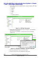
Installing the Plug-Ins . . . . . . . . . . . . . . . . . . . . . . . . . . . 4-1
Go to the OST Plug-in Downloads screen
(System > Chassis > OST > OST Plug-in Downloads). . . . 4-2
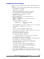
Installing the Solaris Package . . . . . . . . . . . . . . . . . . . . . . 4-3
Uninstalling the Solaris Package . . . . . . . . . . . . . . . . . . . . 4-4
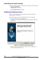
Installing the Windows Plug-In . . . . . . . . . . . . . . . . . . . . . 4-4
Installing the Linux Plug-In . . . . . . . . . . . . . . . . . . . . . . 4-11
Uninstalling the Linux Plug-In . . . . . . . . . . . . . . . . . . . . . 4-11
Installing the SUSE Linux Plug-In . . . . . . . . . . . . . . . . . . 4-11
Uninstalling the SUSE Linux Plug-In . . . . . . . . . . . . . . . . 4-11
Installing the AIX Plug-In . . . . . . . . . . . . . . . . . . . . . . . . 4-12
Uninstalling the AIX Plug-In . . . . . . . . . . . . . . . . . . . . . . 4-12
Installing the Symantec Appliance Plug-In . . . . . . . . . . . . 4-12
Configuring Storage Servers . . . . . . . . . . . . . . . . . . . . . . 4-13
Adding a Disk Volume to the Storage Server . . . . . . . 4-15
Editing Credentials. . . . . . . . . . . . . . . . . . . . . . . . . . 4-16
Editing the Node Configuration . . . . . . . . . . . . . . . . . 4-17
Delete Disk Volume . . . . . . . . . . . . . . . . . . . . . . . . . 4-17
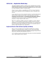
OST A.I.R. – Replication Made Easy . . . . . . . . . . . . . . . . 4-19
Replicate Massive Data Volumes Quickly and Easily . . 4-19
Hitachi Protection Platform and OST A.I.R. Replication
Benefits . . . . . . . . . . . . . . . . . . . . . . . . . . . . . . . . 4-20
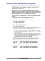
Summary of OST A.I.R. Replication Configuration. . . . . . . 4-21
Creating an OST Storage Server . . . . . . . . . . . . . . . . . . . 4-22
Granular Restore . . . . . . . . . . . . . . . . . . . . . . . . . . . . . . 4-33
NetBackup Accelerator. . . . . . . . . . . . . . . . . . . . . . . . . . 4-33
OST Secure Erasure . . . . . . . . . . . . . . . . . . . . . . . . . . . 4-33
OST Deduplication Control . . . . . . . . . . . . . . . . . . . . . . . 4-34
OST Identifying the Backup Agent . . . . . . . . . . . . . . . . . 4-34
Terminology List . . . . . . . . . . . . . . . . . . . . . . . . . . . . . . 4-35
5
Monitoring Your S1500 ...........................................5-1
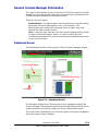
General Console Manager Information. . . . . . . . . . . . . . . . 5-2
Dashboard Screen . . . . . . . . . . . . . . . . . . . . . . . . . . . 5-2
Administrator Tasks . . . . . . . . . . . . . . . . . . . . . . . . . . 5-3
System Notifications . . . . . . . . . . . . . . . . . . . . . . . . . 5-3
Chassis Status Screen . . . . . . . . . . . . . . . . . . . . . . . . 5-4
The LSI MegaRAID SAS Manager . . . . . . . . . . . . . . . . . . . 5-7
Hardware and Software Requirements. . . . . . . . . . . . . 5-7
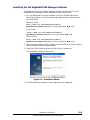
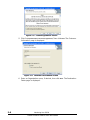
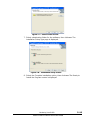
Installing the LSI MegaRAID SAS Manager Software . . . 5-8
Logging Into the LSI MegaRAID SAS Manager (MSM) . 5-12
Contents-4
Hitachi Protection Platform S1500 User Manual
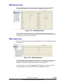
MSM Dashboard View . . . . . . . . . . . . . . . . . . . . . .
MSM Physical View . . . . . . . . . . . . . . . . . . . . . . . .
MSM Logical View . . . . . . . . . . . . . . . . . . . . . . . . .
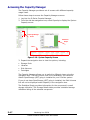
Accessing the Capacity Manager . . . . . . . . . . . . . . . . . .
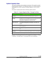
System Capacity View . . . . . . . . . . . . . . . . . . . . . . . . .
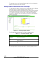
Viewing Additional Information About a Storage Pool
Viewing Additional Information About a Library or
Disk Volume . . . . . . . . . . . . . . . . . . . . . . . . . . . .
Viewing Additional Information About a Cartridge . . .
Libraries View . . . . . . . . . . . . . . . . . . . . . . . . . . . . . . .
Disk Volumes View . . . . . . . . . . . . . . . . . . . . . . . . . . .
Viewing Additional Disk Volume Information. . . . . . .
Cartridges View . . . . . . . . . . . . . . . . . . . . . . . . . . . . .
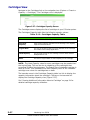
Monitoring Processing Nodes Performance . . . . . . . . . . .
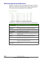
Monitoring Tape Drives Performance . . . . . . . . . . . . . . .
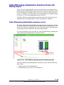
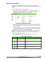
Delta differencing deduplication Summary Screen and
Backup Report . . . . . . . . . . . . . . . . . . . . . . . . . . . . .
Delta differencing deduplication summary screen . . .
Viewing Backup Reports . . . . . . . . . . . . . . . . . . . . .
Replication Monitoring and Reporting . . . . . . . . . . . . . .
Cartridge Status Screen . . . . . . . . . . . . . . . . . . . . .
Replicating Wholesale Cartridges. . . . . . . . . . . . . . .
Job History Table and Performance Graph . . . . . . . .
6
. 5-14
. 5-16
. 5-16
. 5-17
. 5-18
. 5-20
. 5-21
. 5-23
. 5-24
. 5-25
. 5-26
. 5-27
. 5-28
. 5-29
. 5-30
. 5-30
. 5-32
. 5-35
. 5-36
. 5-40
. 5-45
Maintaining Your S1500 ......................................... 6-1
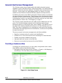
General Host Access Management. . . . . . . . . . . . . . . . . . .6-2
Providing a Hostname Alias . . . . . . . . . . . . . . . . . . . .6-2
Disabling a Host on the SAN . . . . . . . . . . . . . . . . . . . .6-3
Enabling a Previously Disabled Host . . . . . . . . . . . . . .6-3
Removing an Unconnected Host from the SAN List . . . .6-3
Manually Adding Hosts to the List . . . . . . . . . . . . . . . .6-4
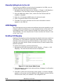
LUN Mapping . . . . . . . . . . . . . . . . . . . . . . . . . . . . . . . . .6-4
Enabling LUN Mapping . . . . . . . . . . . . . . . . . . . . . . . .6-4
Mapping Hosts to a Device (Device View) . . . . . . . . . .6-5
Assigning One or More Hosts to a Device . . . . . . . . . . .6-6
Mapping Devices on a Node . . . . . . . . . . . . . . . . . . . .6-7
Viewing Detailed Information About a Specific Device . .6-8
Clearing All Host Mapping. . . . . . . . . . . . . . . . . . . . . .6-8
Mapping Devices to a Host (Host View) . . . . . . . . . . . .6-9
Assigning One or More Devices to a Host . . . . . . . . . . .6-9
Mapping Devices on a Node . . . . . . . . . . . . . . . . . . . 6-10
Viewing Detailed Information About a Specific Device . 6-11
Clearing All Host Mapping. . . . . . . . . . . . . . . . . . . . . 6-11
Disabling LUN Mapping . . . . . . . . . . . . . . . . . . . . . . 6-12
Editing Cartridges . . . . . . . . . . . . . . . . . . . . . . . . . . . . . 6-12
Moving Cartridges . . . . . . . . . . . . . . . . . . . . . . . . . . . . . 6-14
Contents-5
Hitachi Protection Platform S1500 User Manual
Moving Cartridges Used by Tape Image Replication . . 6-14
Changing Cartridge Capacity. . . . . . . . . . . . . . . . . . . 6-15
Changing Write Access. . . . . . . . . . . . . . . . . . . . . . . 6-15
Deleting Cartridges . . . . . . . . . . . . . . . . . . . . . . . . . . . . 6-15
Deleting Cartridges Used by Tape Image Replication . 6-16
Deleting Cartridges with Data Erasure . . . . . . . . . . . . 6-17
Deleting Cartridges without Data Erasure. . . . . . . . . . 6-18
Editing Libraries . . . . . . . . . . . . . . . . . . . . . . . . . . . . . . 6-18
Destroying a Library . . . . . . . . . . . . . . . . . . . . . . . . . . . 6-20
Destroying a Tape Drive . . . . . . . . . . . . . . . . . . . . . . . . 6-22
Saving Configuration Settings . . . . . . . . . . . . . . . . . . . . . 6-23
Restoring Configuration Settings. . . . . . . . . . . . . . . . . . . 6-24
Creating a Support Ticket. . . . . . . . . . . . . . . . . . . . . . . . 6-25
Performing System Maintenance Tasks . . . . . . . . . . . . . . 6-28
Restarting the VTL . . . . . . . . . . . . . . . . . . . . . . . . . . . . 6-28
Restarting the Console Manager and GUI. . . . . . . . . . 6-29
Restarting the Processing Node . . . . . . . . . . . . . . . . 6-30
Shutting Down the Processing Node . . . . . . . . . . . . . 6-31
Restarting Replication Services . . . . . . . . . . . . . . . . . 6-32
S-Series VTL and Delta Differencing Deduplication Best
Practices . . . . . . . . . . . . . . . . . . . . . . . . . . . . . . . . . . 6-33
VTL and Delta Differencing Deduplication Technology Best
Practices Summary List . . . . . . . . . . . . . . . . . . . . . . . . 6-34
Delta Differencing Deduplication Technology Capacity
Planning and Sizing . . . . . . . . . . . . . . . . . . . . . . . . . . . 6-37
Delta Differencing Deduplication Cartridge
Management. . . . . . . . . . . . . . . . . . . . . . . . . . . . . 6-37
System Sizing . . . . . . . . . . . . . . . . . . . . . . . . . . . . . 6-37
Operational Considerations. . . . . . . . . . . . . . . . . . . . . . . 6-39
Maximum Path Lengths . . . . . . . . . . . . . . . . . . . . . . 6-39
Allocating and Filling Cartridges . . . . . . . . . . . . . . . . 6-39
Allocating Your S-Series System Storage Properly . . . . 6-40
Moving or Deleting Cartridges and Data Erasure. . . . . 6-40
Notifications . . . . . . . . . . . . . . . . . . . . . . . . . . . . . . 6-40
Using Storage Pools. . . . . . . . . . . . . . . . . . . . . . . . . 6-41
Backup Job Naming Considerations . . . . . . . . . . . . . . 6-42
Performance and Tuning Optimization. . . . . . . . . . . . . . . 6-43
Optimum VTL and Delta Differencing Deduplication
Technology Configuration. . . . . . . . . . . . . . . . . . . . 6-43
Network Transmission Load Guidelines . . . . . . . . . . . . . . 6-43
Oracle RMAN Script Integration . . . . . . . . . . . . . . . . . . . 6-44
Windows Server Best Practices . . . . . . . . . . . . . . . . . . . . 6-44
Preventing Windows Event Log Errors by Disabling the
Removable Storage Manager . . . . . . . . . . . . . . . . . 6-44
Symantec NetBackup and Delta Differencing Deduplication
Technology. . . . . . . . . . . . . . . . . . . . . . . . . . . . . . . . . 6-45
Multistreaming Storage Groups in an MS Exchange
Contents-6
Hitachi Protection Platform S1500 User Manual
Information Store . . . . . . . . . . . . . . . . . . . . . .
Volume Pools . . . . . . . . . . . . . . . . . . . . . . . . . .
Default Block Size and Number of Buffers . . . . . .
Do Not Set a Maximum Fragment Size . . . . . . . . .
You Must Use Supported NetBackup Libraries and
Drives. . . . . . . . . . . . . . . . . . . . . . . . . . . . . . .
NetBackup Best Practices for Replicating in a
High-Latency Environment . . . . . . . . . . . . . . . .
TSM and Delta Differencing Deduplication Technology
Collocation . . . . . . . . . . . . . . . . . . . . . . . . . . . .
Concurrent Mount Points . . . . . . . . . . . . . . . . . .
Device Pathnames . . . . . . . . . . . . . . . . . . . . . . .
Keep Mount Point . . . . . . . . . . . . . . . . . . . . . . .
Mount Retention . . . . . . . . . . . . . . . . . . . . . . . .
Relabelscratch . . . . . . . . . . . . . . . . . . . . . . . . . .
Versioning. . . . . . . . . . . . . . . . . . . . . . . . . . . . .
Backupset Backup . . . . . . . . . . . . . . . . . . . . . . .
NetWorker and Delta Differencing Deduplication
Technology . . . . . . . . . . . . . . . . . . . . . . . . . . . . . .
Minimize the Number of Pools. . . . . . . . . . . . . . .
Maximizing Deduplication Effectiveness . . . . . . . .
Windows Device Configuration . . . . . . . . . . . . . .
Linux Device Configuration . . . . . . . . . . . . . . . . .
UNIX Device Configuration . . . . . . . . . . . . . . . . .
NDMP. . . . . . . . . . . . . . . . . . . . . . . . . . . . . . . .
Operational Best Practices . . . . . . . . . . . . . . . . . . . .
Key Metrics . . . . . . . . . . . . . . . . . . . . . . . . . . . .
Reporting . . . . . . . . . . . . . . . . . . . . . . . . . . . . .
Reviewing Operational Changes . . . . . . . . . . . . . . . .
Configuring and Using the HPP Support Portal . . . . . .
Accessing the HPP Support Portal . . . . . . . . . . . . . . .
HPP Support Portal Information . . . . . . . . . . . . . . . .
Dashboard Screen . . . . . . . . . . . . . . . . . . . . . . .
Profile Information. . . . . . . . . . . . . . . . . . . . . . .
A
.
.
.
.
. 6-45
. 6-45
. 6-45
. 6-45
. . . 6-46
.
.
.
.
.
.
.
.
.
.
.
.
.
.
.
.
.
.
.
.
. 6-46
. 6-47
. 6-47
. 6-47
. 6-47
. 6-47
. 6-47
. 6-48
. 6-48
. 6-48
.
.
.
.
.
.
.
.
.
.
.
.
.
.
.
.
.
.
.
.
.
.
.
.
.
.
.
.
.
.
.
.
. 6-49
. 6-49
. 6-49
. 6-50
. 6-51
. 6-51
. 6-51
. 6-52
.6-52
. 6-52
. 6-53
. 6-54
. 6-55
. 6-56
. 6-57
. 6-57
S1500 Components, LEDs, and SpecificationsA-1
Hitachi Compute Rack 220S . . . . . . . . . . . .
Physical Characteristics of S-Series Systems .
Component Locations. . . . . . . . . . . . . .
Power consumption . . . . . . . . . . . . . . .
Hitachi Compute Rack 220S Specifications . .
B
.
.
.
.
.
.
.
.
.
.
.
.
.
.
.
.
.
.
.
.
.
.
.
.
.
.
.
.
.
.
.
.
.
.
.
.
.
.
.
.
.
.
.
.
.
.
.
.
.
. A-1
. A-2
. A-2
. A-6
.A-13
Delta Differencing Deduplication with Oracle
RMAN and SQL Server...............................................B-1
Oracle RMAN Scripting Best Practices with the S-Series Systems B-1
Contents-7
Hitachi Protection Platform S1500 User Manual
Background . . . . . . . . . . . . . . . . . . . . . . . . . . . . . . .B-2
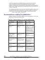
Delta Differencing Deduplication Technology Recommended Practices for Oracle
RMAN . . . . . . . . . . . . . . . . . . . . . . . . . . . . . . . . . . . . .B-5
Good Practice . . . . . . . . . . . . . . . . . . . . . . . . . . . . . .B-5
Better Practice . . . . . . . . . . . . . . . . . . . . . . . . . . . . .B-5
Recommendations for Updating Your RMAN Scripts . . .B-6
NetBackup SQL Server Integration . . . . . . . . . . . . . . . . . .B-9
NetBackup SQL Server Integration Samples . . . . . . . . B-10
SQL Server with Multiple Streams . . . . . . . . . . . . . . . . . . B-12
C
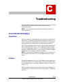
Troubleshooting..................................................C-1
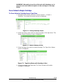
Force Unload Cartridge(s) . . . . . . . . . . . . . . . . . .
Description . . . . . . . . . . . . . . . . . . . . . . . . . .
Solution . . . . . . . . . . . . . . . . . . . . . . . . . . . .
Force Unload a Single Cartridge . . . . . . . . . . .
Force Unload All Cartridges in Use in a Library .
Data Path Failure . . . . . . . . . . . . . . . . . . . . . . . .
Description . . . . . . . . . . . . . . . . . . . . . . . . . .
Solution . . . . . . . . . . . . . . . . . . . . . . . . . . . .
Incompatible Fibre Channel Port Settings . . . . . . .
Description . . . . . . . . . . . . . . . . . . . . . . . . . .
Solution . . . . . . . . . . . . . . . . . . . . . . . . . . . .
D
.
.
.
.
.
.
.
.
.
.
.
.
.
.
.
.
.
.
.
.
.
.
.
.
.
.
.
.
.
.
.
.
.
.
.
.
.
.
.
.
.
.
.
.
.
.
.
.
.
.
.
.
.
.
.
.C-1
.C-1
.C-1
.C-2
.C-3
.C-4
.C-4
.C-5
.C-6
.C-6
.C-6
S1500 Platform Reports.......................................D-1
System Capacity Report . . . . . . . . . . . . . . .
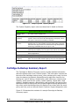
Cartridge-to-Backup Summary Report . . . . .
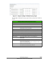
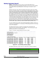
Backup Summary Report . . . . . . . . . . . . . .
Policy-Cartridge Summary Report . . . . . . . .
OST A.I.R History . . . . . . . . . . . . . . . . . . .
OST Optimized Duplication History Report . .
Tape Image Replication Job History Report .
.
.
.
.
.
.
.
.
.
.
.
.
.
.
.
.
.
.
.
.
.
.
.
.
.
.
.
.
.
.
.
.
.
.
.
.
.
.
.
.
.
.
.
.
.
.
.
.
.
.
.
.
.
.
.
.
.
.
.
.
.
.
.
. D-1
. D-2
. D-4
. D-6
. D-7
.D-11
.D-12
E
Regulatory Compliance Notices.............................E-1
F
SNMP V2 Event MIB.............................................F-1
The SEPATON Trap MIB in Text Format. . . . . . . . . . . . . . . F-1
H
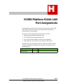
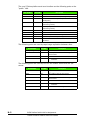
S1500 Platform Public LAN Port Assignments..........H-1
Contents-8
Hitachi Protection Platform S1500 User Manual
Preface
As part of its effort to continuously enhance the performance and
capabilities of its products, Hitachi Data Systems (HDS) from
time to time releases new revisions of its hardware and software.
Therefore, some functions and features described in this
document may not be supported by all models and versions of the
S1500 product family presently in use.
If your unit does not offer a function described in this document,
please open a Customer Support case by visiting the support
portal located at https://deltaview.sepaton.com, or call +1 (866)
657-8400 for upgrade information.
This document describes the features and operation of S1500
platforms running software for the delta differencing
deduplication technology and tape image replication options and
Symantec NetBackup™ OpenStorage (OST).
Preface
Hitachi Protection Platform S1500 User Manual
9
Intended Audience
This document is intended for use by the system and storage administrator,
system programmer, or operator involved in acquiring, managing, or
operating the S1500 system in a backup and restore, deduplication,
replication, management, and reporting environment.
Related Documents
•
Hitachi Protection Platform S1500 Software Installation Instructions
FE-95HPP005-00
•
Hitachi Protection Platform S1500 V8.0 Software Release Notes
RN-S1500-8.0
Please read the Release Notes before installing or using this product. They
may contain requirements and restrictions not fully described in this
document, along with updates and corrections to this document.
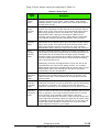
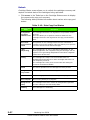
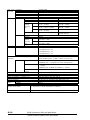
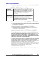
Document conventions
This document uses the following symbols to draw attention to important
safety and operational information.
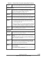
Symbol
Meaning
Description
Tip
Tips provide helpful information, guidelines, or suggestions for
performing tasks more effectively.
Note
Notes emphasize or supplement important points of the main
text.
Caution
Cautions indicate that failure to take a specified action could
result in damage to the software or hardware.
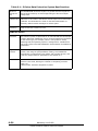
The following typographic conventions are used in this document.
Convention
Description
Bold
Indicates text on a window, other than the window title, including
menus, menu options, buttons, fields, and labels. Example: Click OK.
Italic
Indicates a variable, which is a placeholder for actual text provided by
you or the system. Example: copy source-file target-file
Angled brackets (< >) are also used to indicate variables.
screen/code
Indicates text that is displayed on screen or entered by you. Example:
# pairdisplay -g oradb
< > angled
brackets
Indicates a variable, which is a placeholder for actual text provided by
you or the system. Example: # pairdisplay -g <group>
Italic font is also used to indicate variables.
10
Preface
Hitachi Protection Platform S1500 User Manual
Convention
Description
[ ] square
brackets
Indicates optional values.
Example: [ a | b ] indicates that you can choose a, b, or nothing.
{ } braces
Indicates required or expected values. Example: { a | b } indicates that
you must choose either a or b.
| vertical bar Indicates that you have a choice between two or more options or
arguments. Examples:
[ a | b ] indicates that you can choose a, b, or nothing.
{ a | b } indicates that you must choose either a or b.
underline
Indicates the default value. Example: [ a | b ]
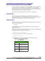
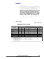
Convention for storage capacity values
Physical storage capacity values (for example, disk drive capacity) are
calculated based on the following values:
Physical capacity unit
Value
1 KB
1,000 bytes
1 MB
1,000 KB or 1,0002 bytes
1 GB
1,000 MB or 1,0003 bytes
1 TB
1,000 GB or 1,0004 bytes
1 PB
1,000 TB or 1,0005 bytes
1 EB
1,000 PB or 1,0006 bytes
Logical storage capacity values (for example, logical device capacity) are
calculated based on the following values:
Logical
capacity
unit
Value
1 block
512 bytes
1 KB
1,024 (210) bytes
1 MB
1,024 KB or 10242 bytes
1 GB
1,024 MB or 10243 bytes
1 TB
1,024 GB or 10244 bytes
1 PB
1,024 TB or 10245 bytes
1 EB
1,024 PB or 10246 bytes
Preface
Hitachi Protection Platform S1500 User Manual
11
1
Introducing the
Hitachi Protection Platform
S1500
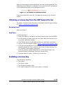
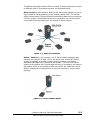
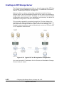
The Hitachi S-Series S1500 Data Protection platform provides a
simple, cost-efficient way to eliminate the risk and financial
impact of data loss in remote and branch offices.
The S-Series platform extends the Hitachi enterprise-class
backup, restore, and deduplication features for efficient storage
of nightly backups in remote and branch offices of large
enterprises. The system emulates Fibre Channel tape drives and
simultaneously supports disk-to-disk backups using the
Symantec OpenStorage (OST) protocol over TCP/IP. Data may be
replicated over IP networks to disaster recovery centers to
eliminate the transport of data via tape.
Key Features of the S-Series Platform
Designed for Multiple Office Environments
The Hitachi S-Series Data Protection platform is an easy-toimplement, manage, and maintain solution that is designed for
offices with limited IT resources. The S-Series platform provides
a scalable, secure, and reliable backup and restore solution that
smoothly integrates into existing environments allowing you to
preserve current policies and procedures.
Introducing the Hitachi Protection Platform S1500
Hitachi Protection Platform S1500 User Manual
1–1
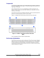
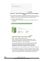
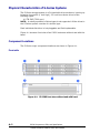
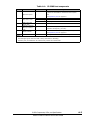
Components
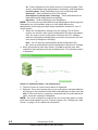
The S-Series storage system is a 2U-sized disk drive enclosure, housing up
to twelve low-profile (1-inch high), 3.5-inch form factor SAS drives of 4.0
Tb/s (up to 7200 rpm).
Each individual disk drive is hot-swappable and field replaceable. The
Hitachi S-Series system provides high reliability by using state-of-the art
disk array technology.
The S-Series hard drives are RAID 6 protected in order to prevent hard drive
faults from causing a backup window to be missed.
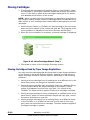
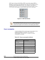
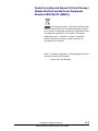
Figure 1-1 displays the front drives and the front view with bezel.
Figure 1-1: S1500 - Front Drives and Front View with
Bezel
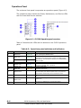
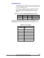
See for detailed S-Series System Specifications.
Performance Optimization
The S-Series can be set up with multiprotocol Fibre Channel and 10 Gigabit
Ethernet ports to provide backup and restore speeds of up to 1500 MB/sec.
S-Series systems are also designed to load-balance backup and restore
functions automatically, thus providing continuous, maximum performance
without taxing your network.
Introducing the Hitachi Protection Platform S1500
Hitachi Protection Platform S1500 User Manual
1–2
Equipped with Deduplication Technology
Delta differencing deduplication technology is a feature of Hitachi that
makes powerful deduplication available to your backup environment. Delta
differencing deduplication is fully integrated with the Hitachi S-Series
systems providing deduplication technology that dramatically reduces
capacity usage without slowing backup or restore performance.
The Delta differencing deduplication technology licensed feature has selfmanagement functions that automatically manage data availability as
deduplication reduces data volume.
When used with tape image replication, the bandwidth required to replicate
data over a WAN can be reduced to as much as 97 percent.
Flexibility and Control
The following features of S-Series systems leverage flexibility and control of
your backup and restore environment:
•
Large number of virtual devices
The Hitachi S-Series systems can configure up to 192 virtual devices
(either a virtual library or virtual tape drive) and up to 64,000 virtual
tape cartridges per system.
•
Advanced network connectivity options
The S-Series systems support Symantec NetBackup OpenStorage (OST)
on 10 Gb Ethernet concurrently with Fibre Channel tape emulation.
•
Keeps pace with data growth
The S-Series systems with storage pooling for multitenancy environments
provide an accurate measurement and forecasting of capacity and
processing needs for budgeting.
S-Series Overview
The Hitachi Protection Platform S-Series provides enterprise-class backup,
restore, and deduplication for efficient storage of backups. The system
emulates Fibre Channel tape drives and simultaneously supports disk-todisk backups using Symantec OpenStorage (OST) protocol over TCP/IP.
Data may be replicated over IP networks to disaster recovery centers to
eliminate the transport of data via tape. Storage capacity and processing
power can be expanded modularly.
S-Series Data Protection Platform Overview
The key topics in this chapter are:
1–3
Introducing the Hitachi Protection Platform S1500
Hitachi Protection Platform S1500 User Manual
Virtual Tape Library
The S-Series Data Protection platform’s Virtual Tape Library (VTL) emulates
a physical tape library. During ingest the data is written to disk and not tape,
so there is significant improvement in backup and restore performance.
The S-Series Data Protection platform with its integrated hardware and
software approach offers significant improvement over tape-based backup
and restore systems. The S-Series platform has several features associated
with its storage that are designed to provide maximum data protection and
availability.
The S-Series platform offers a scalable architecture to meet the demands
of your backup environment. You can create virtual devices (libraries and
tape drives) through the S-Series Console Manager. There can be one or
more tape drives associated with a library.
Delta Differencing Deduplication Technology
Delta differencing deduplication technology is a bundled feature of the SSeries system that makes powerful deduplication technology available to
your backup environment.
Delta differencing deduplication technology intelligently eliminates
redundant portions of backup data. When redundancies are found, delta
differencing deduplication technology eliminates them in each data
sequence. Delta differencing deduplication technology provides industryleading restore and vaulting performance.
Tape Image Replication
The Hitachi remote replication solution allows data centers to electronically
replicate their data from an S-Series system to a geographically remote SSeries system. This licensed application utilizes a secure network
infrastructure to facilitate data movement between Hitachi S-Series
systems.
The Hitachi remote replication solution with deduplication is a highperformance replication solution that leverages delta differencing
deduplication technology, and enables you to protect data faster by
transferring only the changes between backups.
The tape image replication solution is offered with or without a
deduplication license. The S-Series Data Protection platform can be used as
a target or source for tape image replication.
Tape image replication leverages delta differencing deduplication
technology to identify changes since the last backup and transmits only the
changed data (deltas) to the target system, effectively reducing the
required bandwidth by the deduplication ratio for each backup. If delta
differencing deduplication technology is not used, tape image replication
replicates each backup set in full.
Introducing the Hitachi Protection Platform S1500
Hitachi Protection Platform S1500 User Manual
1–4
Hitachi Protection Platform Service Console
The HPP service console is a standard feature of the S-Series Data
Protection platform. The HPP service console monitors the Hitachi Data
Systems Hitachi Unified Storage (HUS) system. Management of Hitachi
Data Systems storage is performed via the LSI MegaRAID Storage Manager.
The HPP service console automatically brings added storage online,
configures devices to their optimal settings, and incorporates the storage
into the system as available capacity.
The Hitachi Hi-Track Monitor “Call Home” Service and Remote Maintenance
Tool provides real-time 24x7 platform monitoring, advanced diagnostics,
and phone-home functionality.
Compression
The S-Series system incorporates dual hardware compression cards in each
node as a standard feature to accelerate the compression and
decompression of stored data. Additionally, spare CPU cycles may be used
to provide additional compression capability. Compression typically results
in about a 2:1 reduction in data, thus doubling storage capacity and halving
the bandwidth required to do I/O.
Some data is highly compressible, while other data (such as encrypted or
precompressed data) will not compress at all. The S-Series Data Protection
platform automatically identifies uncompressible data and does not attempt
to compress it.
Symantec NetBackup™ OpenStorage
OpenStorage (OST) is a licensed feature of S-Series Data Protection
platform. Data Centers are increasingly turning to 10 Gbps Ethernet for new
solutions to backup bottlenecks. Symantec NetBackup provides a powerful
solution called OpenStorage (OST) that implements a disk-like interface to
NetBackup Media Servers while preserving the large-block sequential I/O
advantages of Fibre Channel tape. The S-Series platform can be configured
with one or more OST Storage Servers to provide scalable highperformance backup over multiple 10Gbps Ethernet links.
The Hitachi Data Systems implementation of OST is certified by Symantec
and is designed to offer the highest levels of OST throughput of any
enterprise-class backup platform. OST Storage Servers are analogous to
tape libraries. Each storage server may provide OST services over one or
more pairs of 10Gbps ports. The ports on a 10GigE card can be aggregated
for high throughput. Each Storage Server may offer Storage Volumes from
either a common storage pool, or from different pools if you need to support
multiple companies or subsidiaries in a multitenancy arrangement.
1–5
Introducing the Hitachi Protection Platform S1500
Hitachi Protection Platform S1500 User Manual
Data Erasure
Data erasure is a licensed feature of S-Series Data Protection platform that
provides guaranteed erasure of information on virtual tape cartridges. Data
erasure is implemented as an optional step in the “Delete Cartridge” menu
of the Hitachi Console Manager. This option enables you to schedule all or
selected cartridges for a total data overwrite to ensure that no data can be
retrieved from tape cartridges.
The erasure procedure conforms to the NIST 800-88 standard that is used
in many government agencies and regulated industries to ensure the
complete destruction of sensitive data before storage media are reused or
discarded. Data erasure corresponds to the act of shredding the cartridge
to make sure no information is retrievable from it.
Hitachi Protection Platform Support Portal
The HPP support portal is your online self-service interface with Hitachi
Customer Service. The HPP support portal provides an interactive customer
experience by leveraging a host of case management and self-help tools.
The portal provides real-time visibility throughout the life-cycle of your
support case so that you know the latest status and action plan at all times.
The HPP support portal has updated technical news and bulletins to keep
you informed about changes and new features in the product and
information to help ensure you remain current with the latest releases.
The portal also provides online account management features allowing you
to quickly and easily provide updates to your company’s profile, including
active contacts and important notes for Hitachi to be aware of such as afterhours contacts, the escalation process, and parts delivery instructions to
name a few.
You can visit the Hitachi HPP support portal at:
https://deltaview.sepaton.com
Click on the “New User?” link to begin the secure registration process.
Benefits of Delta Differencing Deduplication and Tape
Image Replication
Some key benefits of the S-Series Data Protection platform include:
•
Multiprotocol support including OpenStorage (OST)
•
Fast Time to Safety
•
Fast Restore for data retrieval and vaulting
•
Superior Console Management and Reporting
•
Scalable Architecture
•
WAN Optimization
Introducing the Hitachi Protection Platform S1500
Hitachi Protection Platform S1500 User Manual
1–6
Keeps Pace with Data Growth
If more storage capacity is needed, simply install additional disk arrays.
Once the new storage is configured and added to an existing storage pool,
the S-Series platform immediately incorporates the additional disk drives
for data storage.
Consolidates IT Infrastructure
Unlike a physical tape library, the S-Series Data Protection platform’s VTL
emulates multiple library types and multiple tape formats in a single
platform. This allows the S-Series platform to provide a flexible platform to
accommodate new data protection strategies as they become available. In
addition, the S-Series Data Protection platform supports user-configurable
virtual cartridges, providing additional flexibility to meet the data center’s
unique needs and environment.
Long-term Vaulting
The S-Series platform provides an easy solution for replicating or vaulting
backups to physical tape. Since the S-Series platform emulates a library
with tape drives to the backup application, you can simply perform a clone
from virtual tape to physical media. This is useful for meeting off-site
requirements or long term vaulting.
Simple Management
The Console Manager provides a graphical user interface for simplified
system management.
Unparalleled Scalability
The S-Series Data Protection platform with delta differencing deduplication
technology allows simple, seamless scaling of storage capacity, and
additional nodes provide more mount points and faster backups and
restores.
Fully Integrated Solution
The S-Series Data Protection platform’s VTL, delta differencing
deduplication technology, and tape image replication interoperate and can
be used with other compression products for even greater data compression
ratios.
Industry’s Fastest Backup and Restore Times
The system is designed to optimize the ingest and restore times for the
latest backup generation by storing it in an undeduplicated format. This
minimizes disk I/O and results in extremely fast restore times. Concurrently
with ingest, delta differencing deduplication technology begins differencing
1–7
Introducing the Hitachi Protection Platform S1500
Hitachi Protection Platform S1500 User Manual
previous backups against the latest one, shrinking them by replacing data
in common with the latest backup by pointers to that data in the latest
generation.
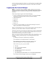
Logging Into the Console Manager
NOTE: For optimal Console Manager viewing, make sure your screen
resolution is set to a minimum of 1024 x 768. Using lower screen resolution
settings can result in excessive scrolling and other undesirable screen
behaviors.
Follow these steps to log into the Console Manager:
1. Launch a supported Internet browser window. The Console Manager
supports the following browser versions and later releases:
•
Internet Explorer 8
•
Firefox 3.6
•
Safari 5.3
•
Chrome 8.0
•
Opera 11.0
2. Access the Console Manager by entering the following for the URL:
https://<ip address of S-Series system>
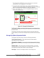
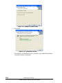
When you first attempt to log in to the S-Series system using the public IP
network, you will receive a Secure Connection Failure Alert.
This alert is sent from your browser as it assumes you want to authenticate
the connection you have. The Hitachi S-Series system does not act as an
authentication authority, so this alert is invalid.
When you receive the Secure Connection Failure Alert, depending on your
browser, it states something similar to the following Mozilla Firefox
message:
IP_Address:443 uses an invalid security certificate.
The certificate is not trusted because it is self signed.
The certificate is only valid for <a id="cert_domain_link”
title="alc10.sepaton.com">alc10.sepaton.com</a>
(Error code: sec_error_ca_cert_invalid)
a. Click OK.
b. Click Or you can add an exception...
c. Click Add Exception.
d. The Add Security Exception page appears.
e. Click Get Certificate.
f.
Click Permanently store this exception, then click Confirm Security Exception.
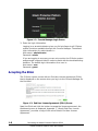
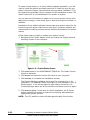
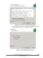
The S-Series Console Manager Login screen is displayed.
Introducing the Hitachi Protection Platform S1500
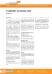
Hitachi Protection Platform S1500 User Manual
1–8
Figure 1-2: Console Manager Login Screen
3. Enter the login information.
Logging in as an administrator gives you full privileges to all S-Series
system functions available through the Console Manager. The default
login information for administrator is:
User name: administrator
Password: admin
If you are logging in as a user, you can only monitor the S-Series system
and generate a support ticket in order to assist with the troubleshooting
behavior. The default login information for a user is:
User name: user
Password: guest
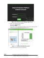
Accepting the EULA
The S-Series system comes with an End User License Agreement (EULA)
that is displayed on the screen when you log in to the Console Manager for
the first time.
Figure 1-3: End User License Agreement (EULA) Screen
Read the EULA and click the button to Accept the license agreement; the
Dashboard screen is displayed. Appendix I, “Hitachi End User License
Agreement,” provides a copy of the online Hitachi End User License
Agreement.
1–9
Introducing the Hitachi Protection Platform S1500
Hitachi Protection Platform S1500 User Manual
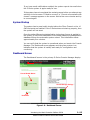
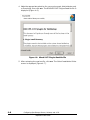
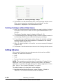
After you have logged in and accepted the end user license agreement, the
Dashboard screen displays. A notification “No license file found” is displayed
on the Notifications pane on the Dashboard screen.
Figure 1-4: No License File Found Notification
Follow the instructions under the to install the license on your S-Series
system.
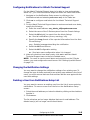
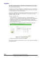
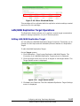
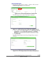
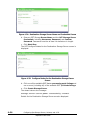
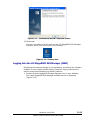
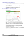
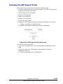
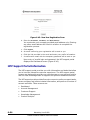
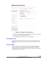
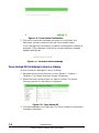
Obtaining a License Key from the HPP Support Portal
The Hitachi S-Series License Generator is available in the HPP support portal
at: https://deltaview.sepaton.com/
Returning Users
Begin with Step 5.
New Users
1. Click New User?
2. Enter a First Name, Last Name, and Email Address, then click REGISTER.
3. You will receive an email within the hour with a Web link that allows you
to provide registration details.
4. Click FINISH and a second email provides you with login credentials.
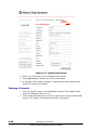
5. Log in to the HPP support portal at https://deltaview.sepaton.com/
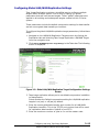
6. Go to Account Management in the left pane, and under Products click on
the gold License Key icon on the far right of your S-Series listing. The
VTL platform License page is displayed.
7. Click the gold key License Download icon on the top far right. The
license.txt dialog is displayed. Save the license.txt file.
8. Continue with the section, Installing a License Key.
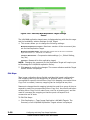
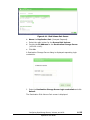
Installing a License Key
The license key identifies:
•
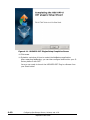
The system
•
The serial number
•
The number of storage LUNs
•
The Hitachi features for which your system is licensed
Introducing the Hitachi Protection Platform S1500
Hitachi Protection Platform S1500 User Manual
1–10
To create virtual devices or to use a Hitachi software application, you will
need to install the Hitachi-provided license file if it was not done by your
Hitachi Customer Support representative during product installation. This
file needs to be accessible via your network for this installation process. The
Hitachi license file is not transferable from system to system.
You can also use this feature to update your current system license when
adding more storage, a new library type or tape device type to emulate, or
software.
Installation of any Hitachi software license requires a system restart for the
license to become active. Make sure to stop any in-progress backups and
restores before installing a license as they would be disrupted by the system
restart.
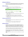
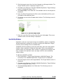
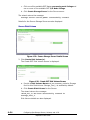
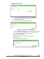
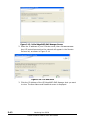
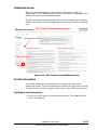
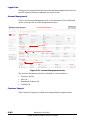
Follow these steps to install or update your system license:
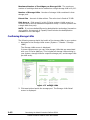
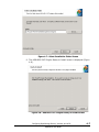
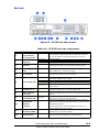
1. Navigate to the Chassis Status screen by clicking the System tab and
selecting Chassis on the left pane.
Figure 1-5: Chassis Status Screen
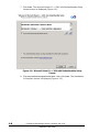
2. Click Install License in the MAINTENANCE TASKS list. The Install License
wizard is displayed.
3. Click Browse and locate the license file saved to your computer.
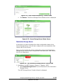
4. Click Next Step to complete the installation process.
The Console Manager validates the license file contents prior to its
installation. The updated license information is now available to your SSeries system. If you did not select a valid Hitachi license file, the
Console Manager warns you of this condition and allows you to try again.
5. Click Return to System. In the case of a fresh installation, the S-Series
system reboots the system to load the new settings and update the
appropriate system services.
NOTE: The VTL platform reboot will take approximately five minutes.
1–11
Introducing the Hitachi Protection Platform S1500
Hitachi Protection Platform S1500 User Manual
If you have email notifications enabled, the system reports via email when
the S-Series system is again ready for use.
If the system has not completed the restart process before you attempt any
activities in the browser a “Failed to connect” or “Cannot communicate with
chassis” message appears on the screen. Wait a few more minutes and try
to connect again.
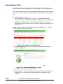
System Startup
The system has to pass health checks before the Fibre Channel or the 10
GbE host ports are enabled. If the S-Series does not start up properly, then
the system will not start.
Once the delta differencing deduplication technology license is applied to
the system, a first-time initialization of the delta differencing deduplication
database follows the automatic system reboot. This initialization takes
approximately five minutes.
You can verify that the system is operational when you launch the Console
Manager. The Dashboard screen appears and the green system icon
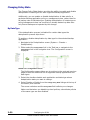
indicates that the system is healthy and ready for configuration and
monitoring.
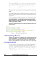
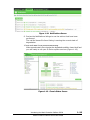
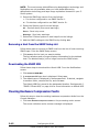
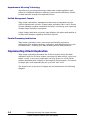
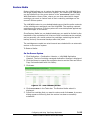
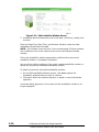
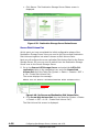
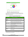
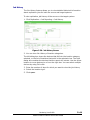
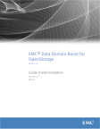
Dashboard Screen
The Dashboard6 screen is the primary S-Series Console Manager display.
Logout Link
Overall Health Status
Overall Storage Savings
Hostname
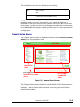
Figure 1-6: Dashboard Screen
Introducing the Hitachi Protection Platform S1500
Hitachi Protection Platform S1500 User Manual
1–12
The left pane displays the S-Series system to be managed through this
Console Manager. The image shows the overall health status of the S-Series
system and lists the S-Series system by its user-defined host name.
If no host name is specified for the S-Series system, the system IP address
shows the system name (default).
The right pane provides a graphical view of the overall delta differencing
deduplication technology statistics, and the deduplicated storage savings
graph.
The Overall Storage Savings shows the total amount of System Data, the
amount of storage used, and the overall amount of storage capacity that is
still available.
The Space Savings from Deduplication graph provides information about
the storage savings achieved with data that has been deduplicated. The
Logical data is the size of all backup data currently retained and visible to
the backup application. The Used data represents the physical storage
capacity whether fully or partially deduplicated, and includes the effect of
hardware compression if enabled.
Additionally, the Notifications screen provides informational citations such
as the following:
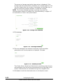
Figure 1-7: System Startup Notifications
Confirming Storage Presence
By default, one storage pool is created out of all available storage when the
system is first installed. To create cartridges and perform backups with your
system, the S-Series system must have at least one storage pool with
storage LUNs associated with it, and enough storage space to store data.
Confirming Storage Pools
The S-Series system writes backup data to the physical storage present in
the system. The physical storage is addressed through storage LUNs
created when the arrays are formatted for the system. The S-Series system
makes these storage LUNs available for user data through storage pools or
storage domains.
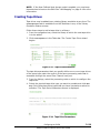
1. Navigate to the Storage Pools Notifications screen (System > Chassis >
Storage Pools).
1–13
Introducing the Hitachi Protection Platform S1500
Hitachi Protection Platform S1500 User Manual
The Storage Pools Notification screen shows the error and event
notifications for the storage pools in the system.
2. To view the status of all storage pools, expand the Storage Pools
selection in the navigation tree by clicking the Plus sign (+) beside that
label. The storage pools available for viewing are displayed.
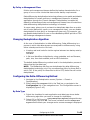
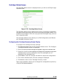
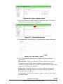
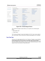
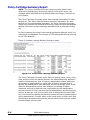
3. Click on the Storage Pool 1 from the expanded listing to view the
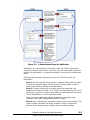
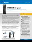
Storage Pool Status screen.
Health Status
Status Parameters
Notifications
Navigation
Figure 1-8: Storage Pool Status Screen
The Storage Pool Status is graphically displayed under the storage pool icon.
Verify that the storage pool in the system is operating normally and displays
the status Good.
The Storage Pool Status screen displays general information about the
storage capacity provided by the storage LUNs associated with that storage
pool.
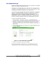
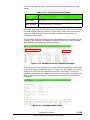
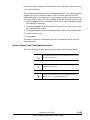
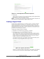
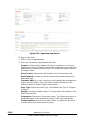
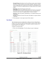
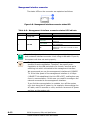
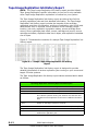
Storage Pool Status Parameter Details
The Storage Pool Status screen shows the following parameters:
Total Physical Capacity - Total usable physical storage capacity
associated with this storage pool.
Allocated User Capacity - Amount of physical storage capacity that can
potentially be consumed by the cartridges currently defined in this storage
pool.
Capacity Used - This is the amount of physical storage in use by the
cartridges defined in that storage pool. It provides an indication of how
much data has already been written to those cartridges.
Cartridges - Number of cartridges defined in that storage pool
Introducing the Hitachi Protection Platform S1500
Hitachi Protection Platform S1500 User Manual
1–14
Maximum Number of Cartridges per Storage LUN - The maximum
number of cartridges that can be created on a single storage LUN is 16,000.
Number of Storage LUNs - Number of storage LUNs contained in that
storage pool.
Extent Size - Amount of data written. The write size is fixed at 32 MB.
Disk Array n - Disk array(s) in this S-Series system. A disk array is a
controller array and its associated expansion arrays. S-Series systems cite
a single disk array only.
NOTE: If you have delta differencing deduplication technology licensed on
your system, the amount of Capacity Used includes the deduplication
metadata on the cartridges.
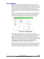
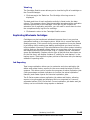
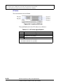
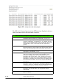
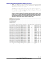
Confirming Storage LUNs
The following screens depict the health of the storage LUNs in your system:
1. Navigate to the Storage LUNs screen (System > Chassis > Storage
LUNs).
The Storage LUNs screen is displayed.
It shows various ways you can view storage LUNs that are associated
with your S-Series platform. This includes all storage LUNs existing in
your system, storage LUNs for a specific storage pool, and storage LUNs
per disk array.
•
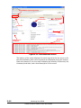
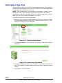
Figure 1-9: Storage LUNs
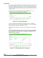
2. Click View button beside the storage pool. The Storage LUNs Detail
screen is displayed.
1–15
Introducing the Hitachi Protection Platform S1500
Hitachi Protection Platform S1500 User Manual
Figure 1-10: Storage LUNs Details
Verify that all the storage LUNs in the system are assigned to a storage
pool and are mounted.
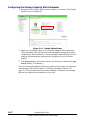
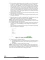
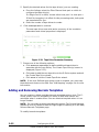
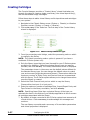
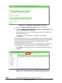
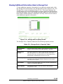
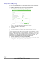
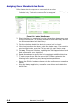
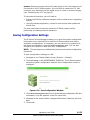
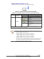
Adding Storage LUNs to a Storage Pool
If you are adding storage to a node, all of the processing node services for
the controller and expansion arrays must be up and available to be able to
add storage.
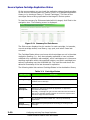
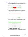
Follow these steps to add storage LUNs to an existing storage pool.
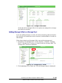
1. Navigate to the Storage Pool 1 screen (System > Chassis > Storage
Pools > Storage Pool 1) where you want to add the storage LUNs. The
Storage Pool 1 screen is displayed.
Figure 1-11: Storage Pool 1 screen
2. Click Add Storage in the Tasks bar. The Add Storage wizard is displayed.
Introducing the Hitachi Protection Platform S1500
Hitachi Protection Platform S1500 User Manual
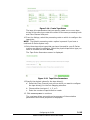
1–16
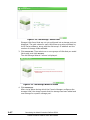
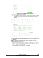
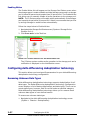
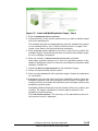
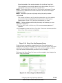
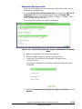
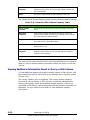
Figure 1-12: Add Storage - Select LUNs
Storage LUNs found that are not yet configured into a storage pool are
displayed. The path values for each LUN shown are auto-populated by
the S-Series software, along with the disk array’s IP address and the
number of storage LUNs available.
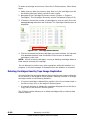
3. Click Format LUNs. Then select one or more groups of LUNs that you would
like to add, and click Next Step.
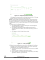
The Add Storage Wizard 2 screen is displayed.
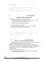
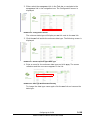
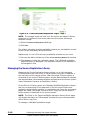
Figure 1-13: Add Storage Wizard 2 Screen
4. Click Add Storage.
After a brief pause during which the Console Manager configures the
storage LUNs, the wizard reports that the storage has been added and
now belongs to a specific storage pool.
1–17
Introducing the Hitachi Protection Platform S1500
Hitachi Protection Platform S1500 User Manual
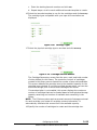
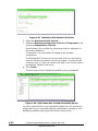
Figure 1-14: Add Storage Completion Screen
You can confirm that the storage LUNs are active by viewing the Storage
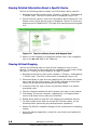
LUN information (see ).
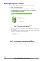
5. Click Return to System.
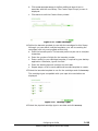
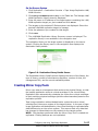
6. You must now Restart the VTL (System > Chassis: MAINTENANCE
TASKS: System Maintenance: Restart VTL).
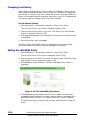
Figure 1-15: Restart VTL Screen
7. Click Restart VTL.
The system reboots and the S-Series Console Manager Login screen is
displayed (Figure 1-16).
Introducing the Hitachi Protection Platform S1500
Hitachi Protection Platform S1500 User Manual
1–18
Figure 1-16: S-Series Console Manager Login Screen
8. Enter your Username and Password.
Username: administrator
Password: admin
The system restarts after approximately three minutes, although it still
appears to be in a degraded state (Figure 1-17).
Figure 1-17: System Needs Attention Screen
The system is in the process of initializing.
1–19
Introducing the Hitachi Protection Platform S1500
Hitachi Protection Platform S1500 User Manual
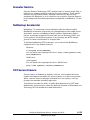
Figure 1-18: Notifications Screen
9. Review the Notifications listings to see the actions that have been
performed.
The red No license file found listing is causing the current state of
degradation.
10. Click and delete the No license file found listing.
After approximately five minutes the degraded condition clears itself and
you are ready to use your S-Series system services (Figure 1-19).
Figure 1-19: Chassis Status Screen
Introducing the Hitachi Protection Platform S1500
Hitachi Protection Platform S1500 User Manual
1–20
2
Configuring the S1500
This section provides the procedures to configure your S-Series
Data Protection platform’s preferences. You must be logged into
the Console Manager as administrator to perform configuration
procedures.
The S-Series Data Protection platform configuration includes:
•
Setting up your network configuration
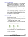
•
Creating virtual devices
•
Configuring delta differencing deduplication technology
Setting Up Your Network Configuration
The S-Series system provides the ability to change your network
configuration settings as well as synchronize with an external
network time protocol (NTP) server.
Use this feature to change your host name, domain name, NTP
settings and time zone settings. You can also change the IP
address, gateway address, net mask, primary and secondary
DNS servers for your processing node, or set up DHCP.
WARNING! Most network configuration changes require a
restart of the S-Series platform, which occurs
automatically when the changes are applied. Make sure
that no backup operations are in progress prior to making
network changes.
Follow these steps to change your network settings:
1. Navigate to the Chassis Status screen (System > Chassis).
2. Click Network Settings in the MAINTENANCE TASKS list. The
Network Settings wizard is displayed.
Configuring the S1500
Hitachi Protection Platform S1500 User Manual
2–1
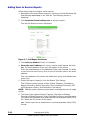
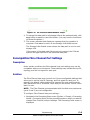
Configuring a Static IP Address for Your System
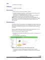
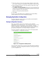
1. Under Node Network Settings, make sure the checkbox Use DHCP (Dynamic
Host Configuration Protocol) is not selected. If selected the IP address,
Gateway address, Net Mask, and Primary and Secondary DNS server
addresses are assigned automatically.
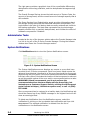
FIGURE 2-1. Network Settings Wizard - Node Network Settings
NOTE: If tape image replication is licensed on your S-Series system, make
sure that the checkbox Use DHCP is not selected.
2. Enter the IP address of your Processing Node.
3. Enter the Gateway IP address of your Processing Node.
4. Enter the Net Mask value.
5. Enter the IP address of your primary DNS server.
6. If you have a secondary DNS server, enter its IP address.
7. Click Apply.
NOTE: Changing from a static IP address to DHCP causes the processing
node to reboot when the changes are applied.
Configuring Your System for DHCP
1. Under Node Network Settings, click the Use DHCP (Dynamic Host
Configuration Protocol) checkbox (Figure 2-1).
2. Click Apply.
Changing Your System Host Name or Domain Name
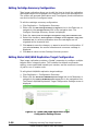
1. Under Chassis Network Settings, enter a new system name in the Host Name
field.
FIGURE 2-2. Network Settings Wizard - Chassis Network Settings
Configuring the S1500
Hitachi Protection Platform S1500 User Manual
2–2
Following are host naming restrictions:
•
Invalid host names include noden, sren, and Head_n, where n
represents a number.
•
Do not use underscores in the host name; for example, myhost is a
valid host name, and my_host is an invalid host name;
•
The host name can only contain alpha numeric values and a hyphen
(see restriction below);
•
The host name cannot begin or end with '-' a (hyphen);
• The host name cannot contain any other special characters.
NOTE: If you are running tape image replication, and you change your the
host name, then you must perform the steps in “Renaming the Host
System” on page 3-30 under tape image replication.
2. Enter a new system domain name in the Domain Name field.
3. Click Apply.
Synchronizing Your System to an External NTP Server
1. Under NTP Settings, enter the IP address of your primary NTP server
(Figure 2-2).
2. If you have a secondary NTP server, enter its IP address.
3. Click Apply.
The S-Series system will synchronize its system clock to the specified NTP
server.
Configuring Your System Time Zone Settings
This feature allows you to change the time zone of the S-Series system to
match your local time zone. Emailed S-Series system status reports will
then reflect your local time.
1. Under Time Zone Settings, select the Geographical Zone of your S-Series
system from the listings (Figure 2-2).
2. Select the Country from the listings.
3. Select the Time Zone corresponding to the selection made above.
4. Click Apply.
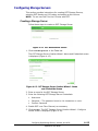
Configuring Your System 10 GbE NIC Network
The system provides you with an option to configure a dual-port 10 Gigabit
Ethernet (10 GbE) network interface controller (NIC) for supporting
NetBackup OST.
1. Select the Bond/Unbond checkbox to enable bonding 10 Gigabit Ethernet
(10 GbE) network interface controller (NIC) on a particular processing
node.
2–3
Configuring the S1500
Hitachi Protection Platform S1500 User Manual
FIGURE 2-3. Network Settings Wizard - 10 GbE NIC Network Settings
2. Enter the IP Address, Gateway Address, and Net Mask value for the 10 GbE NIC
port on your processing node x. The Device Name is assigned
automatically.
3. Click Apply.
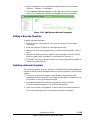
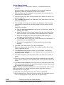
Editing Accounts
There are two user types supported by the Console Manager:
Administrator: The administrator has full Console Manager privileges
and can edit system parameters and make changes to virtual devices.
The default login information for the administrator is:
User name: administrator
Password: admin
User: The user can only monitor the S-Series system and generate a
support ticket in order to assist with troubleshooting. The user cannot
modify system parameters and cannot add, edit, or delete virtual
devices. The default login information for a user is:
User name: user
Password: guest
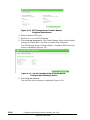
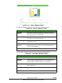
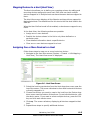
Changing the Password
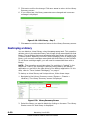
1. Navigate to the Chassis Status screen (System > Chassis).
2. Click Edit Accounts in the MAINTENANCE TASKS list. The Edit Accounts
screen is displayed.
FIGURE 2-4. Edit Accounts Screen
3. Enter the current password for the user type you intend to change.
4. Enter the new password.
5. Confirm the new password by retyping it.
6. Click Apply Settings.
7. Click Next to confirm the change. Otherwise, click Cancel.
NOTE: Changing the password restarts the Console Manager after the
change is confirmed.
8. A message appears on the screen confirming that the password has
been successfully changed.
Configuring the S1500
Hitachi Protection Platform S1500 User Manual
2–4
9. Click Close. The browser window closes.
10.Open a new browser session and log into your system using the new
password.
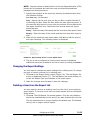
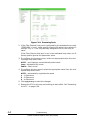
Setting User Preferences
There are several parameters you can set that affect the format of
information displayed on the screens. These parameters include the
administrator’s email address, polling frequency, etc. These values also
appear in the alert notifications and support tickets and assist in system
identification.
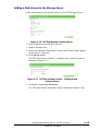
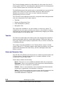
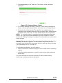
Changing the User Preferences
1. Navigate to the Chassis Status screen (System > Chassis).
2. Select User Preferences by clicking on the User Preferences in the
MAINTENANCE TASKS list. The User Preferences screen is displayed.
3. Specify a frequency (in seconds) after which to check the health status
of the system components. The default value is 15 seconds. The
maximum value is 60 seconds.
4. Enter the number of most recent notifications to make available for
viewing. The number of notifications should be in the range of 0 to 1000.
The default value is 512.
NOTE: Hitachi strongly recommends you fill in the contact information
fields. This information is included in support tickets and assists in system
identification during troubleshooting.
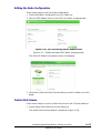
5. Enter a description for the location of the S-Series system in the Location
field and a company name in the Company field.
The location, company name, contact, email and serial number fields are
included in reports and support tickets mailed to Hitachi Customer
Support. You can help us resolve your problem quickly by ensuring this
information is complete and correct.
6. Enter a description (system administrator or support) to indicate whom
to contact about the S-Series system in the Contact field.
7. In the Contact Phone field, enter a telephone number for the system
contact person.
8. In the Email field, enter the system administrator’s email address.
9. Enter the warranty serial number of your S-Series system in the
Warranty Serial Number field.
10.The S-Series system allows you to have DeltaView™ Reports
automatically sent to the Hitachi Customer Support team. Click
DeltaView Reports if you want to enable this facility.
These reports will help the Customer Support team to evaluate your
storage environment.
Click the link Learn more to display more information about the DeltaView
Reports.
11.Click Apply Settings to save the changes.
2–5
Configuring the S1500
Hitachi Protection Platform S1500 User Manual
Configuring Notifications, a Mail Server, Reports, and
SNMP Alerts
The S-Series system continuously monitors the status of its components,
capacity and performance.
The Console Manager provides three different options to receive S-Series
system information for monitoring and planning. These options are:
•
Notifications
•
Reports
•
SNMP Alerts
The Console Manager provides several screens that display current S-Series
system status. In addition, the data relative to these screens can be emailed
to the specified users in the form of a Comma-Separated Value (CSV) file.
These reports are described in Table 2-1. The S-Series system has reporting
capabilities that allow you to configure the S-Series system to alert one or
more users of detected events and errors via email.
NOTE: While opening the emailed-CSV file in Microsoft Outlook, the
browser alters the appearance of some fields. You must import the CSV file
into Excel and reset the format from “General” to “Text.”
Setting Up Notifications
You will need to configure your email server as well as the email address of
each user to receive notifications.
Adding Users to Receive Email Alerts
1. Navigate to the Notifications Setup screen by clicking on the
Notifications tab and selecting Notifications Setup in the Tasks bar.
2. Click Add to configure email alerts for a single user.
3. For the user to receive event and error alerts, specify the following:
a. Enter the user’s email address.
b. Select the name of the S-Series system from the Chassis listings.
c. Select the type of alert to report from the Alerts listings.
All - Send all notifications (errors, warnings, info)
Errors - Send only errors
Warnings - Send only warnings
None - Do not send any notifications
d. Specify the format of the reported information by selecting from the
Alert Format listings.
Short - Abbreviated message describing the notification
Long - Detailed message describing the notification
e. Specify the source of the notifications from the Event Source listing:
Configuring the S1500
Hitachi Protection Platform S1500 User Manual
2–6
All - Send notifications from all the sources (Processing Node, Disk
Arrays, delta differencing deduplication technology, and Replication)
Processing Node- Send notifications from the processing node
Disk Arrays - Send notifications from Disk Arrays
Delta Differencing Deduplication Technology - Send notifications from
delta differencing deduplication technology
Replication - Send notifications from Replication
NOTE: The event sources delta differencing deduplication technology and
Replication are only available when you have delta differencing
deduplication technology and tape image replication licensed on your SSeries system.
f.
Select the Configuration setting from the listings. The S-Series
system can send an auto-saved configuration file that is generated
from the most current configuration whenever the VTL software
detects configuration changes have occurred in the previous 24-hour
time period (midnight to midnight).
None - Do not send an automatically saved configuration file.
All - Send an automatically saved configuration file when it changes.
4. When all selections have been made, click Add to add the user and
respective alert settings to the list of added users. The following screen
is displayed.
FIGURE 2-5. Notifications Setup - List of Added Users
5. The list of users to receive email alerts is displayed.
6. Optional: If you have already set up your mail server, test each address
by clicking on the checkbox beside that email address and then click Test
Email. If the email server is properly configured and the email address is
valid, a success message is displayed.
NOTE: You must configure an email server for users to be able to receive
email alerts and reports from the S-Series system. See “Setting Up a Mail
Server” on page 2-9 for additional information.
2–7
Configuring the S1500
Hitachi Protection Platform S1500 User Manual
Configuring Notifications for Hitachi Technical Support
For the Hitachi Technical Support team to be able to view and evaluate
alerts 24/7, you must follow these steps and enter the exact fields cited:
1. Navigate to the Notifications Setup screen by clicking on the
Notifications tab and selecting Notifications Setup in the Tasks bar.
2. Click Add to configure email alerts for the Hitachi Technical Support
team.
3. For the Hitachi Technical Support team to receive event and error alerts,
specify the following:
a. Enter the email address: [email protected]
b. Select the name of the S-Series system from the Chassis listings.
c. Select the All alert(s) to report from the Alerts listings.
All - Send all notifications (errors, warnings, info)
d. Specify the Long format of the reported information from the Alert
Format listings.
Long - Detailed message describing the notification
e. Select the All Event Source.
f.
Select the All Configuration setting
All - Send auto-save configuration when it is changed
4. When all selections have been made, click Add to add the Hitachi
Technical Support team to the list of added users.
NOTE: For users to receive email alerts and reports from the S-Series
system, you must configure the email server. See “Setting Up a Mail Server”
on page 2-9.
Changing the Notification Settings
You may want to change the notification settings of an existing user. To
change the type of alerts received for an existing user address in the list of
users, you must remove that user first and then add the user again with the
new alert settings.
Deleting a User from Notifications Setup List
You may want to remove an existing user from the list of users receiving
notifications. To remove a user from the list on the Notifications Setup
screen:
1. Select the email address you intend to delete by clicking on the checkbox
besides it.
2. Click Remove.
The list refreshes and no longer displays that user’s email address. The
deleted user(s) will no longer receive email alerts.
Configuring the S1500
Hitachi Protection Platform S1500 User Manual
2–8
Setting Up a Mail Server
For users to receive notifications and reports from the S-Series system of
events, errors, and system configuration settings, you must configure the
mail server to process emails received from the S-Series system.
Adding a Mail Server
To configure your main server from the Notifications screen:
1. Click Mail Server Setup in the Tasks bar. The Mail Server Setup screen is
displayed.
FIGURE 2-6. Mail Server Setup Screen
2. Enter the address for the mail server that processes messages from the
S-Series system.
3. Select the chassis that uses the mail server from the listings.
4. Click Add to add the mail server settings to the Mail Server list.
5. Repeat steps 2 to 4 for each additional mail server you want to add to
the Mail Server list.
Deleting a Existing Mail Server
To remove an email server from the list of available mail servers on the Mail
Server Setup screen:
1. Click Remove for the server you want to delete from the list.
The list refreshes and no longer displays the deleted server.
Setting up Reports
The S-Series system has powerful reporting capabilities that allow you to
download or send reports via email on System Capacity, Cartridge-toBackup Summary, Backup Summary, Policy-Cartridge Summary, OST AIR
Replication History, OST Optimized Duplication History, and Tape Image
Replication Job History. Email reports are attached to an email as a Zip file.
You will need to configure your mail server before adding the users to
receive email reports. See “Setting Up a Mail Server” on page 9.
The S-Series system reports include System Capacity, Cartridge-to-Backup
Summary, Backup Summary, Policy-Cartridge Summary, and Replication
Job History report.
NOTE: Multiple system reports are sent as an email attachment in a single
zip file.
2–9
Configuring the S1500
Hitachi Protection Platform S1500 User Manual
These S-Series system reports are described in Table 2-1:
TABLE 2-1. Report Types
Report
Types
Description
System
Capacity
Report
Lists space utilization information such as total physical capacity,
capacity reserved for the system, usable capacity, used capacity,
available capacity, logical data, system ratio, and the percentage of
storage space savings.
Cartridge-toBackup
Summary
Report
Lists detailed information about the backup sets on an S-Series
system. This information includes barcode of the cartridge, backup
name, client, policy used, the time when the backup started, deltadifferencing algorithm used for the backup set, type of backup,
deduplication status, data type, total physical capacity of the
cartridge, space reserved for system, usable capacity, logical data,
used capacity, available capacity, deduplication ratio, and more.
Backup
Summary
Report
The Backup Summary report lists detailed information about the
backup sets on an S-Series system. This information includes backup
name, client, policy used, the time when the backup started, deltadifferencing algorithm used for the backup set, type of backup,
deduplication status, data type, logical size, physical size, and more.
PolicyCartridge
Summary
Report
The Policy-Cartridge Summary report lists cartridge information for
each backup set. This report lists the backup summary information for
each backup and its corresponding cartridges. Policy-Cartridge
Summary report is an extension of the Backup Summary report and
provides detailed backup information of each cartridge associated
with a particular backup set.
Additionally, the Policy-Cartridge Summary report also lists all the
cartridges that were used in each backup session. The cartridge
details include name of the cartridge under the column Type, current
deduplication state of the cartridge and the backup size before
deduplication and after deduplication.
OST AIR
Replication
History
Report
The OST A.I.R History report lists A.I.R information for tracking
duplication jobs and determining the efficiency of transfers. This
report lists the OST A.I.R information for all duplications from the
Source system.
OST
Optimized
Duplication
Report
The OST Optimized Duplication History Report lists Optimized
Duplication information for tracking duplication jobs and determining
the efficiency of transfers. This report lists the OST Optimized
Duplication information for all duplications from the Source system.
Tape Image
Replication
Job History
Report
Provides a list of all the existing tape image replication jobs. The
report includes the barcode of the cartridge replicated, start and end
time of replication, size in MB, total data transfer time in seconds,
source location of the cartridge, target location, and more.
The Tape Image Replication Job History report provides Hitachi tape
image replication information. While you might see this report listing
as available and could request that it be sent to you, the report will
contain tape image replication information only if you have tape
image replication licensed on your system.
Configuring the S1500
Hitachi Protection Platform S1500 User Manual
2–10
Adding Users to Receive Reports
Follow these steps to configure email reports:
1. Navigate to the Report Setup screen by clicking on the Notifications tab
and selecting Report Setup in the Task bar. The following screen is
displayed.
2. Click Schedule/Download Reports to add job reports.
The Add Job Report screen is displayed.
Figure 2-7: Add Report Job Screen
3. Click Delivery Method: Email or Download.
4. Enter the email address of a user to receive email reports and click
Add. The email address of the user will appear on the screen.
Enter the email address of any additional users, and click Add. To delete
a user from the list of users, click on the red x button next to the email
address.
The users added on this screen are added as a group, and deleted as a
group only.
5. Select the type of report(s) from the Report Type listings.
The S-Series system reports include System Capacity, Cartridge-toBackup Summary, Backup Summary, Policy-Cartridge Summary, OST
AIR Replication History, and Replication Job History.
NOTE: Multiple system reports are sent as an email attachment in a single
zip file.
6. The Report type options System Capacity, Cartridge-to-Backup
Summary, Backup Summary, Policy-Cartridge Summary, and Replication
Job History are available as an attached comma-separated value (CSV)
file. Select the file format of the report:
CSV - Sends report as an attachment in comma-separated value (CSV)
format.
2–11
Configuring the S1500
Hitachi Protection Platform S1500 User Manual
NOTE: Reports sent as an attachment in a Comma-Separated Value (CSV)
format can be imported and read into most commercial spreadsheet
packages and word processors.
7. Specify the schedule of the report by selecting the desired value from
the Schedule listings:
One-Time only - On-demand.
Daily - Reports can be sent once per day or after a regular interval of
time during the day. Select the time when the daily report are sent. If
you want the daily report to recur, enter the number of hours after which
the report should be sent. Select the time interval when this report
should be sent.
Weekly - Select the day of the week and the time when this report is sent.
Monthly - Select the day of the month and the time when this report is
sent.
8. When all the selections have been made, click Save to add the user(s)
and report settings. The following screen is displayed.
FIGURE 2-8. Report Setup Screen - List of Added Users
9. The list of users configured to receive email reports is displayed.
Additional users can be added to the list of users by clicking on Add More.
Changing the Report Settings
You may want to change the report settings of an existing user. To change
the type of reports received for an existing user:
1. Click Edit on the Report Setup screen (Figure 2-8). The Add Report Job
screen is displayed (Figure 2-7). The Add Report Job screen allows you
to edit the Report Type and Schedule of the email report.
2. Make the changes and click Save to save the changes,
Deleting a User from the Report List
You may want to remove an existing user from the list of users receiving
email reports. To remove a user from the email reports list from the Report
Setup screen:
1. Click Edit. The Edit Report Job screen appears. Click the red checkbox
beside the email address for the user(s) you want to delete from the list.
The list refreshes and no longer displays the deleted user. The deleted
user(s) will no longer receive reports.
Configuring the S1500
Hitachi Protection Platform S1500 User Manual
2–12
Deleting a Report from the List
You may want to remove an existing report from the list of reports. To
remove a report from the Report Setup screen:
1. Click Remove for the report you want to delete. The list refreshes and no
longer displays the deleted report.
Configuring SNMP Settings
The S-Series system can be configured to send alerts to specific
management station addresses using the Simple Network Management
Protocol (SNMP) when it detects errors or specific events. The management
station uses applications such as SNMP Manager or HP OpenView to handle
these traps.
If the S-Series system detects an error condition on such events as drive
failures, power supply failures, fan failures, or temperature abnormalities,
it generates a trap with the Hitachi Object Identifier (OID) and the error
condition in text format and sends it to the management station. If email
alerts are also configured, it sends similar error information to the
designated email addresses.
The Hitachi SNMP trap outputs a single variable with the OID
of.1.3.6.1.4.1.8082.7.1. This variable is a string with five parameters.
This string has the following format:
“ChassisId: <S-Series system serial number>; Management URL:
http://<fully qualified name of S-Series system>; Event
Severity: <INFO | WARNING | ERROR>; Fault Message:
<component: message>; Fault Component: <breadcrumb
indicating element level of reporting source>”
Installing the MIB in Your Management Application
The Download SNMP MIB on the Notifications screen allows you to download the
Hitachi MIB. See “Downloading the SNMP MIB” on page 2-15.
You can view the SNMP MIB in Appendix J, “SNMP V2 Event MIB.” The
contents of this string are built from the S-Series event that initiated
generation of the trap. The five parameters contained in this string are:
Chassis ID – The serial number of the S-Series system. This value is
defined when the S-Series software is initially installed.
Management URL – The fully qualified name of the S-Series system.
This value is defined when the S-Series software is initially installed.
Event Severity – The severity of the S-Series event that has generated
the trap. This value can be:
ALL - A component or element’s operating condition has degraded or
failed. For applications, a reported warning or error has occurred.
2–13
Configuring the S1500
Hitachi Protection Platform S1500 User Manual
WARNING - A component or element’s operating condition has
degraded. The component is still functional, but performance may be
compromised. For applications, a limit is being approached.
This can be the number of retries allowed for an operation or a
threshold has been exceeded.
ERROR - A component or an element within a component has failed.
For applications, this indicates an operation failed to complete
successfully.
Fault Message – This value indicates the type of component and a
high level description of the issue. For example, “S- Series
Processing Node: Link Down” indicates that a communications link in
one of the processing nodes has failed. The Fault Component
parameter indicates the link and the processing node reporting the
event.
Fault Component – This is a breadcrumb indicating the source of
the event being reported. It has the format “fully qualified name of
system->S-Series component->[sub-level component/info].” For
example, “alc03.sangate.com->node0->FibreChannel0” indicates
that an event involving host link 0 (port 0 on the HBA card) on
processing node 0 has occurred.
Adding a Host to Receive SNMP Alerts
To configure the S-Series system to send traps to a management station,
follow these steps:
1. Navigate to the SNMP Setup screen by clicking on the Notifications tab
and selecting SNMP Setup in the Tasks bar.
FIGURE 2-9. SNMP Setup Screen
2. Enter the hostname for the management station that processes traps
from the S-Series system.
3. Enter the community string value to be passed with the Management
Station’s set and get commands. This is typically public.
4. Specify the source of the notifications from the Event Source listing:
All - Send notifications from all the sources (Processing Node, Disk
Arrays, delta differencing deduplication technology, and Replication).
Processing Node - Send notifications from processing node
Disk Arrays - Send notifications from Disk Arrays
Delta Differencing Deduplication Technology - Send notifications from
delta differencing deduplication technology
Replication - Send notifications from Replication
Configuring the S1500
Hitachi Protection Platform S1500 User Manual
2–14
NOTE: The event source delta differencing deduplication technology and
Replication are only available when you have delta differencing
deduplication technology and tape image replication licensed on your SSeries system.
5. Select the SNMP trap version from the listings:
1 - For devices configured to use SNMP Version 1.
2c - For devices configured to use SNMP Version 2c.
6. Select the Severity type from the listings:
All - Send all alerts (errors and warnings).
Errors - Send only errors.
Warnings - Send only warnings.
7. Select the S-Series system to send traps from the listings.
8. Add the SNMP settings to the SNMP list by clicking Add.
Removing a Host from the SNMP Setup List
Follow these steps to remove an SNMP host from the list of hosts receiving
SNMP traps. From the SNMP Setup screen:
1. Click Remove for the host you want to delete.
The list refreshes and no longer displays information for the deleted
host. The deleted host(s) will no longer receive the SNMP alerts.
Downloading the SNMP MIB
Follow these steps to download the Hitachi MIB. From the Notifications
screen:
1. Click Download SNMP MIB.
2. A File Download dialogue box is displayed. Select Save.
3. The default name is displayed in the File name field. If desired, navigate
to another folder, rename the file, and click Save.
The Hitachi MIB file is saved to the designated location. See Appendix J,
“SNMP V2 Event MIB,” on page 414 for more information on Hitachi MIB.
Clearing Hardware Compression Faults
Follow this step to clear the existing hardware compression faults from the
Console Manager:
1. Click Clear Hardware Compression Faults on the processing nodex screen.
The screen refreshes and a success message is displayed.
2–15
Configuring the S1500
Hitachi Protection Platform S1500 User Manual
Oversubscribing
NOTE: Oversubscription is automatically enabled for certain Hitachi
features such as delta differencing deduplication technology; in this case
the system will not allow you to disable it. However, you should review this
section to ensure it is configured appropriately. Also, Hitachi advises you to
set up an email alert for when the configured storage pool capacity
threshold is reached. See “Configuring Notifications, a Mail Server, Reports,
and SNMP Alerts” on page 2-6 for more information on setting up these
alerts.
When you create cartridges, the S-Series system defines those cartridges
in the storage pool but does not reserve the amount of storage space
specified for the cartridge size. It is only when user data is written to a
cartridge by the backup application that storage space is consumed.
Figure 2-10: Cartridge Summary
This oversubscription feature permits configuring your system for
anticipated storage growth. When the oversubscription feature is enabled,
you can configure cartridges you anticipate you might need beyond your
current capacity and later you can add physical storage seamlessly.
NOTE: Use of this feature carries the risk of running out of physical storage
capacity when not anticipated and requires careful planning of your storage
needs and upgrades and a review of your policies. Hitachi highly
recommends that you consult with your Hitachi Customer Support
representative for assistance to use this feature properly.
As part of the oversubscription feature, you need to specify a storage pool
capacity threshold level for notification purposes. When the consumed
storage pool capacity reaches this threshold, the Console Manager notifies
you via email and alert messages that you need to add more storage.
Configuring the S1500
Hitachi Protection Platform S1500 User Manual
2–16
Configuring the Storage Capacity Alert Parameter
1. Navigate to the Chassis Status screen (System > Chassis). The Chassis
Status screen is displayed.
Figure 2-11: Chassis Status Screen
2. Specify a percentage value for the Storage Capacity Alert parameter.
This percentage value is the threshold of available storage pool space
remaining for alert notification. This percentage value applies to all the
existing and subsequent storage pools configured in your S-Series
system.
3. Click Apply Settings to save these values. (Scroll down to access the Apply
Settings button, if necessary.)
Prior to creating cartridges the first time, make sure you have a storage pool
with storage LUNs as described in “Confirming Storage Presence” on
page 2-8. This ensures that the Console Manager recognizes the storage
devices and makes them available for your use.
2–17
Configuring the S1500
Hitachi Protection Platform S1500 User Manual
Creating Virtual Devices
To use the S-Series Data Protection platform, you need to create virtual
devices to emulate your libraries and tape drives or modify those already
configured. You also need to create cartridges for your backup data.
NOTE: Prior to creating cartridges the first time, make sure you have a
storage pool with storage LUNs as described in“Getting Started” on page 21. This ensures that the Console Manager recognizes the storage devices
and makes them available for your use.
This section assumes that you have logged into the Console Manager as
administrator.
See “Managing Virtual Devices” on page 6-1 for information on how to
perform additional operations associated with your virtual devices such as
deleting devices, moving cartridges to another library or the FireSafe, or
mapping devices to specific hosts. The S-Series Data Protection platform
provides a “FireSafe” for cartridges. Moving cartridges to the “FireSafe”
causes the S-Series platform to mark those cartridges as vaulted, making
them unavailable for use by a backup application.
Creating a Library
The Console Manager provides a “Create Library” wizard that takes you
through the steps to create a single new library, the virtual tape drive(s),
and the associated empty cartridges.
Follow these steps to add a virtual library and its tape drives and cartridges
to your system:
1. Navigate to the Chassis Status screen (System > Chassis) or Libraries
Summary screen (System > Chassis > Libraries).
2. Click Create Library in the Tasks bar. The first step of the Create Library
wizard is displayed.
Figure 2-12: Select Library Emulation Type
3. From the processing node listings, select the processing node on which
to configure the library.
NOTE: The Hitachi processing node x option is present if you have a
multinode S-Series system only.
Configuring the S1500
Hitachi Protection Platform S1500 User Manual
2–18
4. Only the library types that you have licensed for your S-Series system
are active for selection. Select the physical library type you want to
emulate, and click Next Step. The Library Parameters screen is displayed.
The parameters shown in the screen are the default values defined for
the selected library type. You can change the default values to match
your environment (physical system and license). These values define the
maximum number of Slots, Ports, and Devices that can be associated
with this library. The S-Series system allows you to change these values
once the library is created.
5. Select the Fibre Channel host port on which to map the library. Choose
either host port 0 or host port 1.
6. Enter the Library Name if you want to change the default library name
to one of your choice.
7. Enter the maximum number of cartridge Slots, Import/Export Ports, and
Tape Drives for the library emulation, and click Next Step.
NOTE: Specifying fewer Slots than a physical library of the type you
selected can result in the failure of your backup application to see or access
all cartridges associated with the library.
8. By default, all hosts connected to the S-Series system have access to all
virtual devices. Click Create Library to acknowledge this message and
continue.
The new library now exists and a summary of its emulation parameters
and virtual properties is displayed.
Figure 2-13: Library Parameter Summary
9. Choose one of the following options:
a. Click Create Tape Drive(s) to continue defining the virtual tape drives to
associate with the new library. The Create Tape Drive(s) screen is
displayed.
b. Click Cancel to exit the Create Library wizard.
NOTE: Clicking Cancel exits the Create Library wizard. The library does
exist at this time, however, it has no virtual tape drives associated with it.
These devices can be added at a later time. Canceling from the wizard prior
to this step exits the wizard without creating the library.
2–19
Configuring the S1500
Hitachi Protection Platform S1500 User Manual
Figure 2-14: Create Tape Drives
The tape drive parameters that you specify create one or more tape
drives of the same type under the control of the same processing node
and Fibre Channel host port.
10.From the listings, select the processing node on which to configure the
tape drive.
NOTE: The Hitachi processing node x option is present if you have a
multinode S-Series system only.
11.Only those tape drive types that you have licensed for your S-Series
system are active for selection. Select the physical tape drive type you
want to emulate and click Next Step.
The Tape Drive Parameters screen is displayed.
Figure 2-15: Tape Drive Parameters
12.Specify the desired values for the tape drive(s).
a. Select the Fibre Channel host port on which you want to configure
the tape drive(s) for the Port Mapping selection.
b. Choose either host port 0, 1, 2, or 3.
c. Enter the number of tape drives to create.
13. Click Create Tape Drive to continue.
The new tape drives now exist and a summary of the emulation
parameters and virtual properties is displayed.
Configuring the S1500
Hitachi Protection Platform S1500 User Manual
2–20
Figure 2-16: Tape Drive Parameter Summary
If the tape drive is dual-ported, the Port Map lists ports 0 and 1. The tape
drive’s LUN value on both ports is also shown here.
NOTE: Devices created on processing nodes have 4-digit virtual device
IDs. The first digit of the ID is the processing node number followed by
the device’s virtual device ID on that node. For example, a tape drive with
a virtual device ID of 1 on node 0 has a device ID of 1, but on processing
node 1.
14.Choose one of the following options:
a. Click Create Cartridges to continue defining the virtual cartridges to
associate with the new library.
b. Click Create more Tape Drive(s) to define additional tape drives to
associate with the new library. The Create Tape Drive(s) screen is
displayed.
c. Click Cancel to exit the Create Library wizard.
Figure 2-17: Create Cartridges
15.Define the barcode template to use with the cartridges for this library.
Although you can define multiple templates, you will be creating the
cartridges with only one template at this time.
a. Enter the barcode prefix. The barcode prefix may be one to six alpha
characters.
a. Enter the number of digits for the barcode number.
b. Enter a suffix for your cartridge barcodes, if required by your backup
application. Otherwise, ignore the field.
2–21
Configuring the S1500
Hitachi Protection Platform S1500 User Manual
c. Enter the starting barcode number and click Add.
d. Repeat steps a to d for each additional barcode template to create.
16.Select the barcode template to use for the cartridges and click Next Step.
The cartridge types compatible with your tape drive emulation are
displayed.
Figure 2-18: Cartridge Types
17.Select the physical cartridge type to emulate and click Next Step.
Figure 2-19: Cartridge Size and Number
The Cartridge Parameters screen lists the open, used, and total number
of slots defined for this library. The maximum number of cartridges
created in this library cannot exceed the number of open slots available.
This screen defaults the cartridge size to the standard capacity for the
cartridge type selected. If you have multiple storage pools, you can also
select the storage pool in which those cartridges will reside.
If oversubscription is not enabled, this screen displays the maximum
number of cartridges that can be created based on both physical storage
capacity remaining and number of available slots remaining in the
library.
NOTE: The S-Series system requires a certain amount of storage overhead
for each cartridge you create for cartridge content information. It
automatically subtracts this amount from the available capacity.
18.Specify the number of cartridges to create and the cartridge size.
Configuring the S1500
Hitachi Protection Platform S1500 User Manual
2–22
The amount of storage required by these values is displayed. If the
storage required exceeds what is available, the overage appears in red.
You can change either the number of cartridges, the cartridge size, or
both to correct the overage condition, or allow the overage.
NOTE: The Console Manager permits an overage only when the
oversubscription feature is enabled. See “Oversubscribing” on page 4-17
for instructions on how to set up this feature.
Figure 2-20: Storage Pool Selection
19.Click Next Step.
Figure 2-21: Cartridge Summary
20.The new cartridges now exist and a summary of the emulation
parameters and virtual properties is displayed. Click Next.
Figure 2-22: Summary Screen
The Create Library wizard has finished and a new library, tape drive(s),
and cartridges now exist and are summarized on the final page of the
wizard. These devices are accessible through the navigation tree.
21.Click Return to exit the wizard and return to the System screen.
2–23
Configuring the S1500
Hitachi Protection Platform S1500 User Manual
NOTE: If the User-Defined Host Access mode is enabled, you must map
these devices to hosts on the SAN. See “LUN Mapping” on page 6-4 for more
information.
Creating Tape Drives
Tape drives may be added to an existing library emulation at any time. The
Create Tape Drive task is available from the Tasks bar in any of the Library
Emulation Status screens.
Follow these steps to add a tape drive to a library:
1. From the navigation tree, select the library to which the new tape drive
is to be added.
2. Click Create Tape Drive in the Tasks bar. The Create Tape Drive wizard
begins.
Figure 2-23: Tape Drive Emulations
The tape drive parameters that you specify define one or more tape drives
of the same type under the control of the same processing node that is
accessible through the same Fibre Channel host port.
3. From the listings, select the processing node on which to configure the
tape drive.
4. Select the physical tape drive type you want to emulate and click Next
Step. Only those tape drive types that you have licensed are active for
selection. The Tape Drive Parameters screen is displayed.
Figure 2-24: Tape Drive Parameters
Configuring the S1500
Hitachi Protection Platform S1500 User Manual
2–24
5. Specify the desired values for the tape drive(s) you are creating.
a. From the listings, select the Fibre Channel host port on which to
configure the tape drive(s).
If a Single Port is in effect, choose either host port 0 or host port 1.
If Dual Port mapping is in effect for this processing node, both ports
are preselected for you.
b. Enter the number of tape drives to create.
6.
Click Create Tape Drive to continue.
The new tape drives now exist and a summary of the emulation
parameters and virtual properties is displayed.
Figure 2-25: Tape Drive Parameter Summary
7. Choose one of the following options:
a. Click Create more Tape Drive(s) to define additional tape drives to
associate with the new library. The Create Tape Drive(s) screen is
displayed (Figure 2-23).
b. Click Finish to add the new tape drive to the S-Series system and exit
the Create Tape Drive wizard.
c. Click Cancel to exit the Create Tape Drive wizard.
NOTE: If the User-Defined Host Access mode is enabled, you must map
these devices to hosts on the SAN. See “LUN Mapping” on page 6-4 for more
information.
Adding and Removing Barcode Templates
You can create or delete cartridge barcode templates at any time. The SSeries system uses the template you select to label and number the
cartridges when it creates them. You can delete a template when it is no
longer needed.
NOTE: Do not create cartridge barcodes with spaces. The Console Manager
reports an error if a space is used for Digit Length or Starting # on the Add/
Remove Barcode Templates page.
To modify barcode templates:
2–25
Configuring the S1500
Hitachi Protection Platform S1500 User Manual
1. Select Cartridges in the expanded navigation tree for your chassis
(System > Chassis > Cartridges).
2. Click Add/Remove Barcode Templates in the Tasks bar of the Cartridges
screen. The Add/Remove Barcode Templates screen is displayed.
Figure 2-26: Add/Remove Barcode Templates
Adding a Barcode Template
To add a barcode template:
1. Enter a prefix for the barcode. This prefix may be up to six alpha
characters.
2. Enter the number of digits for cartridge sequencing.
3. Optional: If your backup application requires a barcode suffix, enter it
here.
4. Specify the starting numeric value for the cartridges. As the S-Series
system creates each cartridge, it increments this value by 1.
5. Click Add. The screen refreshes with the new template values added to
the barcode selection list.
Deleting a Barcode Template
The Console Manager does not allow you to delete a barcode template that
has been used to create cartridges that are currently present in the S-Series
system.
1. To remove a barcode template, all cartridges using that barcode
templates must be removed. See “Deleting Cartridges” on page 6-14 for
information on how to delete cartridges.
2. Click Remove beside the barcode template you want to delete.
A window appears asking you to confirm the deletion.
3. Click Yes to delete the template, or No to cancel the delete operation.
The screen refreshes when the deletion operation completes.
Configuring the S1500
Hitachi Protection Platform S1500 User Manual
2–26
Creating Cartridges
The Console Manager provides a “Create Library” wizard that takes you
through the steps to create a single new library, the virtual tape drive(s),
and the associated empty cartridges.
Follow these steps to add a virtual library and its tape drives and cartridges
to your system:
1. Navigate to the Chassis Status screen (System > Chassis) or Libraries
Summary screen (System > Chassis > Libraries).
2. Click Create Library in the Tasks bar. The first step of the Create Library
wizard is displayed.
Figure 2-27: Select Library Emulation Type
3. From the processing node listings, select the processing node on which
to configure the library.
NOTE: The Hitachi processing node x option is present if you have a
multinode S-Series system only.
4. Only the library types that you have licensed for your S-Series system
are active for selection. Select the physical library type you want to
emulate, and click Next Step. The Library Parameters screen is displayed.
The parameters shown in the screen are the default values defined for
the selected library type. You can change the default values to match
your environment (physical system and license). These values define the
maximum number of Slots, Ports, and Devices that can be associated
with this library. The S-Series system allows you to change these values
once the library is created.
5. Select the Fibre Channel host port on which to map the library.
Choose either host port 0 or host port 1.
6. Enter the maximum number of cartridge Slots, Import/Export Ports, and
Tape Drives for the library emulation, and click Next Step.
NOTE: Specifying fewer Slots than a physical library of the type you
selected can result in the failure of your backup application to see or access
all cartridges associated with the library.
7. By default, all hosts connected to the S-Series system have access to all
virtual devices. Click Create Library to acknowledge this message and
continue.
The new library now exists and a summary of its emulation parameters
and virtual properties is displayed.
2–27
Configuring the S1500
Hitachi Protection Platform S1500 User Manual
Figure 2-28: Library Parameter Summary
8. Choose one of the following options:
a. Click Create Tape Drive(s) to continue defining the virtual tape drives to
associate with the new library. The Create Tape Drive(s) screen is
displayed.
b. Click Cancel to exit the Create Library wizard.
NOTE: Clicking Cancel exits the Create Library wizard. The library does
exist at this time, however, it has no virtual tape drives associated with it.
These devices can be added at a later time. Canceling from the wizard prior
to this step exits the wizard without creating the library.
Figure 2-29: Create Tape Drives
The tape drive parameters that you specify create one or more tape
drives of the same type under the control of the same processing node
and Fibre Channel host port.
9. From the listings, select the processing node on which to configure the
tape drive.
NOTE: The Hitachi processing node x option is present if you have a
multinode S-Series system only.
10.Only those tape drive types that you have licensed for your S-Series
system are active for selection. Select the physical tape drive type you
want to emulate and click Next Step.
The Tape Drive Parameters screen is displayed.
Configuring the S1500
Hitachi Protection Platform S1500 User Manual
2–28
Figure 2-30: Tape Drive Parameters
11.Specify the desired values for the tape drive(s).
a. Select the Fibre Channel host port on which you want to configure
the tape drive(s) for the Port Mapping selection.
b. Choose either host port 0 or host port 1.
c. Enter the number of tape drives to create.
12. Click Create Tape Drive to continue.
The new tape drives now exist and a summary of the emulation
parameters and virtual properties is displayed.
Figure 2-31: Tape Drive Parameter Summary
If the tape drive is dual-ported, the Port Map lists ports 0 and 1. The tape
drive’s LUN value on both ports is also shown here.
NOTE: Devices created on the processing node have 4-digit virtual
device IDs. The first digit of the ID is the processing node number followed
by the device’s virtual device ID on that node. For example, a tape drive
with a virtual device ID of 1 on node 0 has a device ID of 1, but on
processing node 1.
13.Choose one of the following options:
a. Click Create Cartridges to continue defining the virtual cartridges to
associate with the new library.
2–29
Configuring the S1500
Hitachi Protection Platform S1500 User Manual
b. Click Create more Tape Drive(s) to define additional tape drives to
associate with the new library. The Create Tape Drive(s) screen is
displayed.
c. Click Cancel to exit the Create Library wizard.
Figure 2-32: Create Cartridges
14.Define the barcode template to use with the cartridges for this library.
Although you can define multiple templates, you will be creating the
cartridges with only one template at this time.
a. Enter the barcode prefix. The barcode prefix may be one to six alpha
characters.
b. Enter the number of digits for the barcode number.
c. Enter a suffix for your cartridge barcodes, if required by your backup
application. Otherwise, ignore the field.
d. Enter the starting barcode number and click Add.
e. Repeat steps a to d for each additional barcode template to create.
15.Select the barcode template to use for the cartridges and click Next Step.
The cartridge types compatible with your tape drive emulation are
displayed.
Figure 2-33: Cartridge Types
16.Select the physical cartridge type to emulate and click Next Step.
Configuring the S1500
Hitachi Protection Platform S1500 User Manual
2–30
Figure 2-34: Cartridge Size and Number
The Cartridge Parameters screen lists the open, used, and total number
of slots defined for this library. The maximum number of cartridges
created in this library cannot exceed the number of open slots available.
This screen defaults the cartridge size to the standard capacity for the
cartridge type selected. If you have multiple storage pools, you can also
select the storage pool in which those cartridges will reside.
If oversubscription is not enabled, this screen displays the maximum
number of cartridges that can be created based on both physical storage
capacity remaining and number of available slots remaining in the
library.
NOTE: The S-Series system requires a certain amount of storage overhead
for each cartridge you create for cartridge content information. It
automatically subtracts this amount from the available capacity.
17.Specify the number of cartridges to create and the cartridge size.
The amount of storage required by these values is displayed. If the
storage required exceeds what is available, the overage appears in red.
You can change either the number of cartridges, the cartridge size, or
both to correct the overage condition, or allow the overage.
NOTE: The Console Manager permits an overage only when the
oversubscription feature is enabled. See “Oversubscribing” on page 4-17
for instructions on how to set up this feature.
Figure 2-35: Storage Pool Selection
18.Click Next Step.
2–31
Configuring the S1500
Hitachi Protection Platform S1500 User Manual
Figure 2-36: Cartridge Summary
19.The new cartridges now exist and a summary of the emulation
parameters and virtual properties is displayed. Click Next.
Figure 2-37: Summary Screen
The Create Library wizard has finished and a new library, tape drive(s),
and cartridges now exist and are summarized on the final page of the
wizard. These devices are accessible through the navigation tree.
20.Click Return to exit the wizard and return to the System screen.
NOTE: If the User-Defined Host Access mode is enabled, you must map
these devices to hosts on the SAN. See “LUN Mapping” on page 6-4 for more
information.
Configuring the S1500
Hitachi Protection Platform S1500 User Manual
2–32
Oversubscription and delta differencing deduplication
technology
Delta differencing deduplication technology automatically enables
oversubscription of the S-Series system’s backend storage for each storage
pool configured in your S-Series system. This option allows you to free up
additional backend storage.
Graceful Shutdown at 98% Storage Pool Capacity
To avoid filling up the backend storage, warning notifications are displayed
on the Notifications page when the consumed storage pool capacity reaches
a user-configured threshold (System > Chassis: Oversubscription — default
is 90 percent full). If enabled, email notifications are sent to the specified
users. Additional notifications are sent when the storage pool utilization
rises to 95 and then 98 percent full.
The S-Series system will reject all attempts to write data on the cartridges
in this storage pool from the backup application at 98 percent full capacity,
so you must erase unnecessary cartridges to free storage in the storage
pool or add storage beforehand. This ensures that no data is lost when the
storage capacity of a storage pool is full.
NOTE: All read operations will remain unaffected. The cartridges that do
not belong to this storage pool will also remain unaffected.
You cannot hot-add storage while delta differencing deduplication
technology is deduplicating data. The S-Series Console Manager provides
an option to reclaim space after extra storage space has been created by
erasing expired cartridges in the storage pool.
The S-Series system will enable writes automatically if the storage pool
capacity is below 90 percent full. However, the system also provides an
option to enable all write operations manually if the storage pool capacity is
greater than 90 percent full and less than 98 percent full.
The S-Series system provides a Cartridge-to-Backup Summary report to
help you identify the cartridges that are consuming more space and can be
expired to create free storage space. Refer to Appendix F for information on
the Cartridge-to-Backup Summary report.
When the storage pool capacity utilization rises to the user-defined threshold
level, the following scenarios will occur
1. The storage pool is greater than the user-defined threshold level but less
than 98 percent full.
The default value of the capacity threshold level for notification purposes
is 90 percent full. The Console Manager allows you to change this
threshold level.
When the storage utilization for a storage pool rises above the userdefined threshold level the Console Manager notifies you via email and
alert messages.
2–33
Configuring the S1500
Hitachi Protection Platform S1500 User Manual
The following list defines the behavior of the S-Series system when the
capacity consumption of a storage pool is greater than the user-defined
threshold level:
•
Warning notifications are displayed on the Console Manager.
•
If email alerts are configured, emails are sent to the specified users.
•
If SNMP traps are configured, alerts are sent to the management
stations.
• The Reclaim Space link is displayed on the Storage Pool Status screen.
NOTE: Hitachi recommends that you free up extra storage space at this
point.
You can perform the following tasks at this point:
•
Erase Cartridges
•
Reclaim Space
•
Add Storage
2. The backend storage pool capacity is 98 percent full
When the storage pool level is 98 percent consumed, all attempts to
write data are rejected by the S-Series system.
The following list defines the behavior of the system when the storage
pool capacity is 98 percent consumed:
•
Warning notifications are displayed on the Console Manager.
•
If email alerts are configured, emails are sent to the specified users.
•
If SNMP traps are configured, alerts are sent to the management
stations.
•
The Reclaim Space link is displayed on the Storage Pool Status screen.
•
All writes will shut down, and a Writes: Disabled summary is displayed
on the Storage Pool Status screen.
NOTE: Hitachi recommends that you free up extra storage space at this
point.
You can now perform the following tasks:
•
Erase Cartridges
•
Reclaim Space
•
Enable Writes
Erase Cartridges
Erasing cartridges allows you to create extra storage space by erasing or
relabeling the cartridges in the scratch pool.
Erasing data from expired cartridges that contain deduplicated data will not
free the same amount of storage capacity as a cartridge that contains data
that has not been deduplicated.
Configuring the S1500
Hitachi Protection Platform S1500 User Manual
2–34
The S-Series system provides a Cartridge-to-Backup Summary report to
assist you in identifying the cartridges that are consuming more space and
can be expired to create free storage space in the storage pool.
NOTE: When EMC® NetWorker® attempts to perform backups while in this
condition, it will attempt to write to an available cartridge. This write will not
be successful and NetWorker will retry on the next available cartridge. This
process will repeat until all of the available cartridges have been used. This
can be avoided if the backup is stopped manually.
A Backup Set that Spanned Cartridges Leaves Used Capacity in Cartridges that
Are Not Relabeled
A backup set spanned at least two cartridges, and one of the cartridges was
subsequently relabeled or overwritten. Relabeling the cartridge removed
any knowledge of the backup set from the S-Series because the backup set
was no longer available for deduplication. However, some Used Capacity
remains on the other cartridge(s). And since the S-Series no longer knows
about the backup set associated with the Used Capacity, it displays the
message: There are no backups for this cartridge.
In this instance you should relabel the other cartridge(s).
Cartridge-to-Backup Summary Report
The Cartridge-to-Backup Summary report helps you identify the space
utilization of each cartridge. This report lists the barcode of each cartridge,
disk space usage in bytes, deduplication status, and dependent cartridges,
if any exist.
1. Generate a new Cartridge-to-Backup Summary report using the Report
Setup option (Notifications > Report Setup).
2. Identify the cartridge(s) that can be erased to create free storage using
the Cartridge-to-Backup Summary report.
The following considerations can help you while identifying cartridges to
erase (delete):
•
Cartridges that have a large amount of data written on them and are in
the scratch pool should be erased first.
•
Nondeduplicated cartridges that have no dependent cartridges or few
dependent cartridges should be erased next. Nondeduplicated
cartridges require dependent cartridges to be erased also.
3. After you have identified the cartridges that can be erased, follow the
Erase Cartridge procedure as documented by your backup application:
NOTE: This following procedures are intended to be performed by storage
backup system administrators. Refer to your backup application
documentation for instructions on how to do this.
NetBackup
•
2–35
Use the backup application to expire and relabel the cartridges.
Configuring the S1500
Hitachi Protection Platform S1500 User Manual
TSM
•
Relabel the cartridges.
•
Relabel the cartridges.
NetWorker
Data Protector
•
Right click on a cartridge and select “Recycle.”
•
Once the cartridge is recycled, or if the retention period has expired,
right click on the cartridge and select “Format.”
This rewrites the header and wipes out the data on the cartridge.
Otherwise, you must vault the cartridges off to tape.
NOTE: The S-Series system will enable writes on the storage pool
automatically if the backend storage drops below 90 percent full. Hitachi
recommends you free up enough backend storage to enable writes
automatically.
Reclaiming Space
The Reclaim Space link will appear on the Storage Pool Status screen when
the storage consumed reaches the user-defined threshold level. This task
allows you to schedule reclamation of extra storage created by erasing
cartridges.
After you have erased cartridges from your backup application, you can
schedule space reclamation on the S-Series system.
Follow the steps below to Reclaim Space:
1. Navigate to the Storage Pool Status screen (System > Storage Pools >
Storage Pool n).
2. Click Reclaim Space in the Task bar.
FIGURE 2-38. Chassis Status Screen with the Reclaim Space link
The S-Series system initiates space reclamation and a “Space
Reclamation is scheduled” notification is displayed on the Notification
screen.
Configuring the S1500
Hitachi Protection Platform S1500 User Manual
2–36
Enabling Writes
The Enable Writes link will appear on the Storage Pool Status screen when
the storage space is made available and total storage consumed in a storage
pool is below 98 percent and greater than 90 percent full. The Enable Writes
link allows you to manually enable all write operations to the storage pool.
NOTE: The S-Series system will enable writes automatically if the storage
pool capacity drops below 90 percent full. Hitachi recommends that you free
up enough storage to enable writes automatically.
Follow the steps below to Enable Writes:
1. Navigate to the Storage Pool Status screen (System > Storage Pools >
Storage Pool n).
2. Click Enable Writes in the Task bar.
FIGURE 2-39. Chassis Status Screen with Enable Writes link
The S-Series system enables write operation to the storage pool and a
notification is displayed on the Notification screen.
Configuring delta differencing deduplication technology
This section allows you to set specific parameters for your delta differencing
deduplication technology configuration.
Renaming Unknown Data Types
Delta differencing deduplication technology supports deduplication for all
data types. The delta differencing deduplication technology Configuration
screen displays a list of backup applications and data types. There can be
certain data types, however, that do not fall under a specified category.
Delta differencing deduplication technology allows you to rename these
unknown data types to user-defined names.
To rename an unknown data type:
1. Navigate to the delta differencing deduplication technology screen
(System > Chassis > Deduplication).
2–37
Configuring the S1500
Hitachi Protection Platform S1500 User Manual
2. Either select the Configuration link in the Task bar or navigate to the
Configuration link in the navigation tree. The Configuration screen is
displayed.
FIGURE 2-40. Configuration Screen
The unknown data type will display an Edit link next to the View link.
3. Click the Edit link beside the unknown data type. The following screen is
displayed.
FIGURE 2-41. Rename Special Agent Data Type
4. Enter a name for the unknown data type and click Apply. The screen
refreshes and the new name appears in the list.
FIGURE 2-42. Data Type Renamed Successfully
To change the data type name again click the Edit link and rename the
data type.
Configuring the S1500
Hitachi Protection Platform S1500 User Manual
2–38
Changing Policy State
The Change Policy State feature provides the ability to enable and disable
deduplication of data types for each supported backup application.
Additionally, you can enable or disable deduplication of data sets for a
particular backup application policy or management class, rather than for
all backup sets of that data type. Enabling deduplication of a data type or
policy/management class has no effect on already backed-up data sets only future backups are impacted by this change.
By Data Type
If the deduplication process is disabled for certain data types the
deduplication process skips them.
To enable or disable deduplication by data type for the selected backup
application:
1. Navigate to the Deduplication screen (System > Chassis >
Deduplication).
2. Either select the Configuration link in the Task bar or navigate to the
Configuration link in the navigation tree. The Configuration screen is
displayed.
FIGURE 2-43. Configuration Screen
The Configuration screen allows you to continue to the next and previous
pages to see the additional list of supported backup applications and
data types.
3. Select the checkbox beside each application and data type whose
deduplication state you want to change.
4. Select Disable or Enable from the Change Policy State listings at the top of
the screen, and click GO.
The screen refreshes and the Policy State field reflects your changes.
Make sure that when you disable top-level policies, subordinate policies
of the same type are also disabled.
2–39
Configuring the S1500
Hitachi Protection Platform S1500 User Manual
By Policy or Management Class
Policies and management classes define the backup characteristics for a
group of one or more clients that have similar backup requirements.
Delta differencing deduplication technology allows you to enable and disable
deduplication for certain policies or management classes for a backup
application through the Console Manager. Deduplication is enabled by
default for all backup policies and management classes from all hosts when
delta differencing deduplication technology is licensed.
In some cases, where you do not want to deduplicate data from a certain
set of hosts (defined by a policy or a management class), you can disable
deduplication for that policy or management class only. For example, you
can disable deduplication for one or more NetBackup NDMP policies or TSM
MS Exchange management classes.
Changing Deduplication Algorithm
At the core of deduplication is delta-differencing. Delta-differencing is a
process in which two data streams are analyzed for differences by using
either a backup set level or file level.
•
A backup set level looks for similar regions between two backup sets by
analyzing
the data.
•
A file level identifies similarities by using metadata, such as filename,
path, size, time-last-modified, and an MD5 checksum.
The default delta-differencing method used in the deduplication process is
determined by the data type.
NOTE: The NetBackup raw files are deduplicated by delta differencing
deduplication technology only if the corresponding policy for these files is
set to CA2. If the policy for these files is set to CA3, these files will not be
deduplicated.
Configuring the Delta-Differencing Method
1. Navigate to the Deduplication screen (System > Chassis >
Deduplication).
2. Either select the Configuration link in the Task bar, or navigate to the
Configuration link in the navigation tree. The Configuration screen is
displayed (Figure 2-43).
By Data Type
1. Select the checkbox for each application and data type whose deltadifferencing algorithm you want to change for duplication.
2. Select CA2 or CA3 from the Change Deduplication Algorithm listings at the top
of the screen, and click GO. The screen refreshes and the Deduplication
Algorithm field reflects your changes and a success message is displayed.
Configuring the S1500
Hitachi Protection Platform S1500 User Manual
2–40
By Policy or Management Class
1. Click the Data Type link to see all policies or management classes in use
for that data type. The Policies screen or Management Class screen is
displayed.
2. Select the checkbox for each policy or management class whose deltadifferencing method you want to change.
3. Select CA2 or CA3 from the Change Deduplication Algorithm drop-down at the
bottom of the screen, and click GO. The screen refreshes and the
Deduplication Algorithm field reflects your changes and a success message
is displayed.
FIGURE 2-44. Deduplication Algorithm Changed Successfully
2–41
Configuring the S1500
Hitachi Protection Platform S1500 User Manual
3
Configuring and Using Tape
Image Replication
This section provides information you need to know for installing
and configuring Replication in your environment. This section
assumes that you have logged into the S-Series Console Manager
as the administrator.
Overview and Features of Tape Image Replication
The Hitachi replication solution allows data centers to
electronically replicate data from one S-Series system in one
location to another S-Series system in a different location. The
data can be replicated via LAN/WAN between two S-Series
systems. Replication is based on a mirroring technology that
associates the source system with a target system. The source
system is the S-Series system from which the data is being
replicated and the target system is the S-Series system on
receiving end.
NOTE: The S-Series system makes storage available for user
data through storage pools. If a storage pool used by tape image
replication reaches its capacity, the replication will stop. This is
irrespective of the capacity of the other storage pools.
Key Features of Tape Image Replication
The key features of tape image replication
include:
Optimized Replication via Data Deduplication
Tape image replication leverages data deduplication to enable
only the unique data to be transferred to the target S-Series
system. This enables more data to be expediently transferred to
safety.
Configuring and Using Tape Image Replication
Hitachi Protection Platform S1500 User Manual
3–1
Asynchronous Mirroring Technology
Asynchronous mirroring technology makes tape image replication wellsuited for LAN/WAN replication whereby resources are effectively utilized
for data transfer through user-defined policies.
Unified Management Console
Tape image replication's management features are integrated into the
unified management console. A tape image replication tab in the S-Series
Console Manager window centralizes the setup, monitoring, and reporting
of tape image replication operations.
A tape image replication summary page displays job status and enables a
90-day trend analysis capability and email reports.
Parallel Processing Architecture
Tape image replication uses a concurrent and parallel processing
architecture that enables backups, replication, and deduplication to occur
simultaneously - enabling your data a faster path to data protection.
Implementing Hitachi Replication
Tape image replication associates the S-Series system doing the data
replication with the S-Series system receiving the data using a “source-totarget” model. A source-to-target pair can be a library on one S-Series
system associated with a library on the target S-Series system. The sourceto-target pair could optionally be set up on the “slot” level.
The steps to set up a source-to-target pair are described in the following
diagram.
3–2
Configuring and Using Tape Image Replication
Hitachi Protection Platform S1500 User Manual
Figure 3-1: S-Series System Setup for Replication
Replication is an automated process that, after the initial configuration,
requires no human intervention. However, you can manipulate replication
policies for optimization of network bandwidth or to perform maintenance
tasks.
Following are the steps required to set up the S-Series system for
replication:
Step 1: On the target S-Series system, create a library and cartridges
to receive replication data. On the source S-Series system create a
library that exactly matches the target library.
Step 2: Create a target with a unique name and password, and
assigning the library in Step 1 to it. Define the start and the end slot in
this library, maximum number of simultaneous transfers and maximum
TCP/IP bandwidth to receive replication data.
Once you have created the target, it appears in the tape image
replication tab under LAN/WAN Replication Targets.
Step 3: Next, reference the replication target on the source system. The
source system identifies the target created in Step 2 using the IP
address of the target system, target name, and target library.
Configuring and Using Tape Image Replication
Hitachi Protection Platform S1500 User Manual
3–3
After adding the target on the source system, the target name and IP
address appear under the Destination Libraries. Tape image replication
creates the cartridges on the source S-Series system automatically once
the source and target systems are configured.
Step 4: Replication is an automated process that requires no human
intervention. It is based on the creation of a Mirror Copy Pool that
synchronizes the source and the target based on user-defined policies.
You must create the Mirror Copy Pool in each Destination library on the
source system. The Mirror Copy Pool defines:
1. Start and end Slot. Defining the start and the end Slot allows you to
replicate selected cartridges only. The cartridges that are not within the
Slot range will not be replicated.
2. Library on the S-Series system from where the data is to be replicated.
3. Policy for replication, such as priority and policy details for synchronizing
the source and the target system.
NOTE: Only backups performed after the Mirror Copy Pool is created are
replicated; previous backups are not replicated.
Replication Use Models
Data replication solutions are typically performed to accomplish the
following overall goals:
•
Provide protection against data loss due to operator or machine error.
•
Protect against data loss due to disaster.
•
Provide historical data records.
Protecting against data loss due to operator or machine error is the most
typical use of backup tapes. Many companies perform a combination of full
and incremental backups of their data on a regular basis. These backups are
often kept on site for rapid access in the event data recovery is needed due
to human error (i.e., accidental erasure of files), a malicious computer
program (i.e., virus attack), or a hardware fault (i.e., hard drive crash).
Protecting against data loss due to disaster is the second most common use
of backup tapes. Here, full backups or copies of full backups are made and
transported away from the original data source. These backup tapes are
kept in this off-site secure location for some period of time. Should a
disaster occur (i.e., flood, fire, etc.), the off-site tape can be retrieved and
restored to an alternate data system to facilitate business recovery. This offsite media is often part of a rotation plan in which the media is cycled back
to the source site for reuse on a regular schedule.
Providing a historical data record is the third most common use of backup
tapes. Tape copies of source data are kept for an extended periods of time
as dictated for Sarbanes-Oxley or HIPAA (Health Insurance Portability &
Accountability Act of 1996) compliance. This compliance determines the
media rotation policy.
3–4
Configuring and Using Tape Image Replication
Hitachi Protection Platform S1500 User Manual
The Hitachi replication solution allows multiple S-Series systems to be used
in different ways in the backup process, as described below:
Many-to-One: In this scenario, backups are performed regularly to one or
more central S-Series system(s) from several remote sites. The remote
offices have smaller S-Series systems consolidating data into an enterprise
S-Series system. Should data recovery be necessary, the remote system
could restore the cartridges from the central S-Series system.
Figure 3-2: Many-to-One Model
Active - Passive: In this scenario, one S-Series system supports daily
backups and restores of data. This is the active site. A second S-Series
system is available in another location and its function is to receive
replicated cartridges from the active site system. This second S-Series
system is the passive site. Should data recovery be necessary, the passive
site system could be connected to take over the for the failed site. Active Passive models can be deployed as one-to-one topology or one-to-many
topology.
Figure 3-3: Active-Passive Model
Configuring and Using Tape Image Replication
Hitachi Protection Platform S1500 User Manual
3–5
Active - Active: In this scenario, both S-Series systems support daily
backups and restores of data at separate data centers. Both S-Series
systems replicate cartridges to each other. Should data recovery be
necessary for any of the systems, the second system takes over for the
failed site. Active - Active models are typically deployed as one-to-one
topology.
Figure 3-4: Active-Active Model
Understanding Replication Concepts
Before moving on to the implementation of replication, it is important to
understand the replication concepts.
Active System
An Active System is the S-Series system that sends data to be replicated on
the target S-Series system.
Passive System
A Passive System is the S-Series system that receives the replicated data
from the source S-Series system but does not receive local backup data.
Target System
A Target System is the S-Series system that has been identified to receive
the replicated data.
Source System
A Source System is the S-Series system that sends data to be replicated on
the target S-Series system.
Source
A series of cartridges in a virtual library are the source data to be replicated.
This is the original copy of the backup data, written to and managed by the
source site's backup application.
3–6
Configuring and Using Tape Image Replication
Hitachi Protection Platform S1500 User Manual
Target
A series of corresponding slots and cartridges in another virtual library at
another site in another location that receives data from the source virtual
library. This is the secondary (data recovery) copy of the backup data that
is managed by the replication system.
LAN/WAN Replication Targets
The Replication Target is the library on the target S-Series system where the
replicated data will reside. This library must have the same number of slots
and cartridges to hold the replicated data from the source system. You can
create replication targets using either an existing library on the target SSeries system or a newly created library. While creating a replication target
you also specify the start and end slots of the library to hold the replicated
data.
The target system must have a virtual library and cartridges of the same
type and barcode as on the source to receive replicated data.
A target S-Series system can have multiple replication targets. You create
multiple replication targets on a single target system by mapping different
libraries or different slot ranges within a single library.
You then map the replication target to the library on the source S-Series
system and reserve the specified library and slots for replicated data only.
Destination or Replication Libraries
A Destination Library is the term used to identify the replication library on
the source system. The destination library is also called the replication
library.
The target S-Series system is linked to the source S-Series system using
the IP address or the host name of the target system. After the target
system is connected to the source S-Series system, and the desired target
is selected and authenticated, the available targets are displayed on the
source S-Series system under Destination Libraries as Replication Library.
Adding replication libraries on the source system allows you to view the
target system, its corresponding slots, and its Mirror Copy Pool settings.
Configuring and Using Tape Image Replication
Hitachi Protection Platform S1500 User Manual
3–7
Slots
Like a tape library, the S-Series system shows slots to the backup
application for writing backup data. After the Mirror Copy Pool is created,
the replication job will move cartridges from the source system to the target
system to these slots in the library.
You must select the range of slots in the library while creating the replication
target on the target system. Defining the start and the end Slot allows you
to replicate selected cartridges only. The cartridges that are not within the
Slot range will not be replicated.
These slots are also displayed on the Source S-Series system under the
Destination Library.
The Hitachi tape image replication allows you to edit the slot maps from the
source system.
Mirror Copy Pool
The Mirror Copy Pool acts as an asynchronous mirror between the selected
source system and the replication target library. You can create multiple
Mirror Copy Pools for a single destination library by specifying different slot
ranges within the same replication library.
On the source S-Series system, you could either have one source library
mapped to multiple Mirror Copy Pools, or you could have a separate library
for each Mirror Copy Pool.
In either case, you divide your backup jobs so that high-priority jobs go to
the cartridge set or virtual library that is mapped to the Mirror Copy Pool
with a high-priority policy; and the low-priority jobs go to the other
cartridges or the other virtual library.
Only backups performed after the Mirror Copy Pool is created are replicated.
Existing backups are not replicated.
Policy Window
The Policy Window is created while creating the Mirror Copy Pool on the
source S-Series system. The parameters of the Policy Window define the
time when the data is replicated on the target S-Series system.
The Policy Window settings also have an option to allow active replication
jobs to completion or cancel all active replication jobs without completing
when the Policy Window ends. Additionally, it also provides an option to
allow active replication jobs that have met the specified threshold to reach
completion and cancel others when the Policy Window ends.
3–8
Configuring and Using Tape Image Replication
Hitachi Protection Platform S1500 User Manual
Availability Window
The Availability Window is created while creating the Replication Target on
the target S-Series system. Availability Window settings include the start
day, start time and window duration when the target system will accept
replication data.
The Availability Window on the Target should be always greater than or
equal to the Policy Window on the Source system to allow replication jobs
to complete.
Availability Window Parameters can be set daily (24 hours), weekly, and
monthly. The target is available to receive data as defined in the availability
window settings. The window times are local, if source and target systems
are on different time zones make sure that the availability and policy
windows overlap.
Prerequisites for Using Tape Image Replication
The basic requirements for using tape image replication are:
•
Bidirectional replication between most systems is supported. Open a
Customer Support case by visiting the HPP support portal located at
https://deltaview.Sepaton.com, or call +1 (866) 657-8400.
•
Delta differencing deduplication technology and tape image replication
system licenses. Refer to the section “Licensing Tape Image
Replication” on page 3-10 for licensing details.
•
An operational TCP/IP network with adequate capacity connecting the
S-Series systems.
•
Open the following firewall ports at each site: port 5570 (default for
data replication) and port 22 (SSH port for replication control messages
to the remote node).
•
Open the following Web browser ports: port 80 (HTTP) and port 443
(HTTPS).
•
The target S-Series system requires enough storage space to
accommodate data transfers from the source S-Series system. Open a
Customer Support case by visiting the HPP support portal located at
https://deltaview.Sepaton.com, or call +1 (866) 657-8400 to assist
you in sizing this effort.
•
All processing nodes must have an IP address, net mask, primary and
secondary DNS server IP addresses. See “Network Configuration
Settings” on page 4-1 for information on changing the IP address,
gateway address, net mask, primary and secondary DNS for your
processing nodes.
Configuring and Using Tape Image Replication
Hitachi Protection Platform S1500 User Manual
3–9
On the Source System
Create a virtual library, tape drive, and cartridges to receive backup data.
See “Creating Virtual Devices” on page 5-1for information on creating
virtual devices.
On the Target System
Create a virtual library, tape drive, and cartridges of the same size, type,
and barcode as those on the source system.
Licensing Tape Image Replication
Table 3-1 provides information about licensing requirements to allow you to
run tape image replication.
For customers that require replication and deduplication:
Table 3-1: Replication and Deduplication
Software
Source
S-Series
system
Target
S-Series
system
License
Key
Required
License
Key
Required
VTL
YES
YES
Delta
Differencing
Deduplication
YES
YES
Tape Image
Replication
NO
YES
In an “active-active” scenario, each S-Series system must serve as a
“source” and a “target.”
In a many-to-one scenario, there are multiple S-Series systems replicating
to a single S-Series system. Since each “source” must have an associated
“target,” there will multiple “targets” on the target S-Series system, all of
which must be licensed.
3–10
Configuring and Using Tape Image Replication
Hitachi Protection Platform S1500 User Manual
Seeding Initial Data on S-Series Replication Systems
Seeding is the process of creating your initial, complete mirror of a set of
backup data at the secondary site (remote data center). Seeding is a
necessary starting point for any data recovery operation, and the method
by which you set up seeding initial data depends on how much time you
have to get your tape image replication system operational.
It’s important to note that replication applies only to backups created after
tape image replication is activated (licensed). If you have been
accumulating data on an S-Series system (with or without delta differencing
deduplication technology) for some time before upgrading to tape image
replication, only subsequent backups (that is, beginning with the next set
of backups) are replicated. They are transmitted without deduplication
because the target system has no backups to deduplicate against. This is
why it is important to determine how you are going to seed the target
system to minimize the amount of data replicated during the initial
replication.
Tape image replication requires the virtual tape cartridges (and their
metadata) to be identical on both the source and the target S-Series
systems before replication can be used.
There are two ways to implement this:
•
Copy the cartridges from the source to the target intact over the
network.
•
Copy the cartridges to physical tape, move the physical tapes to the
remote site, and restore them.
LAN Seeding
LAN seeding involves collocating the target S-Series system with the source
S-Series system to create a mirror as fast as possible, then transporting the
target S-Series system to the remote data center. This method is attractive
because it allows the backup operator to test procedures much more
quickly, and to test the recovery procedure locally using a spare media
server. Typically, only a few days elapse before the target is brought online
again and replication can continue.
Configuring and Using Tape Image Replication
Hitachi Protection Platform S1500 User Manual
3–11
WAN Seeding
WAN seeding involves mirroring an S-Series system and database across a
WAN link to matching equipment at the remote data center. Depending on
the bandwidth of the WAN connection, this can be very time consuming.
Realistically, as your use of replication grows, you will find that you are
employing WAN seeding for new backup policies, so even if you started with
a LAN seeding approach, you will almost always do some WAN seeding.
It is important to understand how often new policies will be introduced and
how much data they will generate because the seeding process requires
extra bandwidth and extra landing space on the target system.
Configuring Tape Image Replication
Tape image replication is an option that enables you to replicate data over
a LAN /WAN between Hitachi's S-Series systems using cartridge mirroring
technology. The mirroring technology associates the source system with a
target system. It ensures that the replicated data is kept identical, including
contents, barcodes, and cartridge types. Mirroring is an S-Series system
feature and it is performed without the backup application’s knowledge.
You can configure the Hitachi replication solution to operate in one of two
modes:
•
Tape image replication deduplication mode
•
Tape image replication nondeduplication mode
Tape image replication deduplication mode is a high performance replication
solution that leverages delta differencing deduplication technology, enabling
you to replicate more data faster by transferring only the changes between
backups.
Tape image replication nondeduplication mode copies data byte-for-byte
from the source cartridge to a cartridge on the target system.
Tape image replication configuration requires:
•
Configuring global LAN/WAN replication settings.
•
Creating LAN/WAN replication targets.
• Managing the source replication library.
NOTE: The procedure for configuring replication is identical for both tape
image replication with deduplication and tape image replication without
deduplication.
3–12
Configuring and Using Tape Image Replication
Hitachi Protection Platform S1500 User Manual
Configuring Global LAN/WAN Replication Settings
Tape Image Replication provides a simplified way to configure multiple
targets within a target system. You do this by setting up “global”
parameters that are used across targets. These “global” parameters are
applied to all existing and subsequent targets created on this S-Series
system.
These parameters include the default compression setting for data transfer
and an unencrypted data transfer port number.
To configure the global LAN/WAN replication target parameters, follow these
steps:
1. Navigate to the LAN/WAN Replication Targets screen by clicking the
Replication tab and selecting Tape Image Replication LAN/WAN Target
from the navigation tree.
2. Click Global LAN/WAN Replication Target Settings in the Tasks bar. The following
screen is displayed.
Figure 3-5: Global LAN/WAN Replication Target Configuration Settings
Screen
3. Tape image replication allows you to use default compression in addition
to deduplication.
Select whether the Default compression setting for LAN/WAN replication
targets is on (Yes) or off (No) by default.
4. Enter the unencrypted data transfer port number for all LAN/WAN
Replication transfers. This is the TCP/IP port number that will be used
for replication data transfers. Default is port 5570.
5. Enter the maximum number of jobs to run on the master node.
Configuring and Using Tape Image Replication
Hitachi Protection Platform S1500 User Manual
3–13
6. Click Submit. If the settings were configured successfully, a confirmation
message appears.
Figure 3-6: LAN/WAN Replication Target Settings Modified
Successfully
The global LAN/WAN replication target configuration settings are applied for
all existing and subsequent replication targets.
Creating LAN/WAN Replication Targets
NOTE: The type of library must match on the source and target S-Series
systems.
Creating a LAN/WAN Replication Target allows you to assign a library on the
target S-Series system where the replicated data will reside.
The global LAN/WAN replication target configuration settings are applied to
all the replication targets unless specified otherwise.
On the Target System
1. Click Replication > Tape Image Replication LAN/WAN Targets. The LAN/
WAN Replication Target screen is displayed.
2. Select Create LAN/WAN Replication Target in the Tasks bar. The Create LAN/
WAN Replication Target wizard is displayed.
3–14
Configuring and Using Tape Image Replication
Hitachi Protection Platform S1500 User Manual
Figure 3-7: Create LAN/WAN Replication Target - Step 1
3. Enter a LAN/WAN Replication Target Name.
4. Select the library on the source system where you want to add the target
from the Local Library list.
The available libraries are displayed along with the available slot ranges
on the selected library. See “Creating Virtual Devices” on page 5-1to
create a new library with tape drives and cartridges.
5. Enter a Start Slot and an End Slot for the Mirror Copy Pool from within the
available ranges. If the slot entered does not exist in the available range,
an error message is displayed.
6. Enter the number of Maximum Simultaneous Transfers permitted.
Tape image replication allows you to limit the replication activity on the
target by setting the number of maximum simultaneous replication data
transfers. Default is 8.
7. Select the Maximum TCP/IP Bandwidth for the replication target.
8. Select a Compress Data Transfer option.
9. Enter a unique Password for this replication target. Reenter the password
for verification.
10.Replication jobs can only begin during the availability window. When the
availability window ends, any replication jobs currently in progress will
continue until they complete. No replication jobs can begin until the next
availability window opens.
Availability Window Parameters can be set daily (24 hours), weekly, and
monthly. The target is available to receive data as defined in the
availability window settings.
Click Add Availability Windows. The summary of the parameters entered in
the previous screen is displayed.
Configuring and Using Tape Image Replication
Hitachi Protection Platform S1500 User Manual
3–15
Figure 3-8: Create LAN/WAN Replication Target - Step 2
NOTE: The window times are local, so if the source and target S-Series
systems are in different time zones make sure the source and target
windows overlap.
11.Select the Add Availability Window Settings.
12.Click Add.
The window refreshes, and the availability window you just added is moved
to the Current Availability Windows section.
Repeat steps 11 and 12 for as many availability windows as you need.
13.You can also edit or delete any of the Current Availability Windows if required.
14.Click Submit to create the replication target. The LAN/WAN replication
target summary is displayed. The replication target is now available in
the navigation tree.
Managing the Source Replication Library
Managing the Source Replication Library allows you to link the target
S-Series system with the source S-Series system using the IP address or
the host name of the target system. After the target S-Series system is
connected to the source S-Series system, and the desired target is selected
and authenticated, the available targets are displayed on the source system
under Destination Libraries as Replication Library.
On the Source S-Series system use “Manage LAN/WAN Replication Library”
and the corresponding IP and password to link the source library and
replication target library together in a replication pair. Once the source and
target are linked, the target, slots and Mirror Copy Pool on the target SSeries system is displayed on the source system.
NOTE: The Slots in the Target LAN/WAN replication library at this stage
will display the status as “Unmanaged” because they are not associated
with a Mirror Copy Pool.
To manage a LAN/WAN replication target:
3–16
Configuring and Using Tape Image Replication
Hitachi Protection Platform S1500 User Manual
On the Source System
1. Click Replication > Destination Libraries > Tape Image Replication LAN/
WAN Libraries.
2. Click Manage LAN/WAN Replication Library in the Tasks bar. The Manage LAN/
WAN Replication Library wizard is displayed.
3. Enter the name or IP address of the target system containing the LAN/
WAN replication target you just created and click Submit.
4. The targets on the selected S-Series system are displayed. Select the
desired LAN/WAN replication target to manage.
5. Enter the password you created for that target.
6. Click Submit.
7. The LAN/WAN Replication Library Summary screen is displayed. The
replication library is now available in the navigation tree.
The replication library on the target system is displayed on the source
system. Clicking the library name in the navigation tree displays the
destination library details.
Figure 3-9: Destination Library Details Screen
The Destination Library Details screen displays the name of the library, the
type of library, number of simultaneous transfers, number of slots, the
management URL, and its current availability status.
Creating Mirror Copy Pools
Mirror copy acts as a transparent disk cache to the physical library, so that
the backup application writes to virtual cartridges in the virtual library.
Replication then automatically schedules the copies from virtual cartridges
to their matching physical cartridges (with the same barcodes) based on the
replication policies.
Tape image replication without deduplication copies the entire virtual
cartridge from the source system to the target system. In the case of tape
image replication with deduplication, the virtual cartridge is replicated after
delta-differencing on the source system. This ensures that only data that
has changed is transmitted over the network to the target system.
NOTE: Only backups performed after the Mirror Copy Pool is created are
replicated. Existing backups are not replicated.
Configuring and Using Tape Image Replication
Hitachi Protection Platform S1500 User Manual
3–17
On the Source System
1. Click Replication > Destination Libraries > LAN/WAN Replication
Libraries.
You may need to expand the navigation tree to see the individual
Replication Libraries configured on the source system.
2. Click the library in the navigation tree to display its components (i.e.,
Slots and Mirror Copy Pool).
3. Click the Mirror Copy Pool in the navigation tree under the Library you
want to replicate.
4. Click Create Mirror Copy Pool in the Tasks bar. The Create Mirror Copy Pool
wizard is displayed.
5. The available slot ranges in this library are displayed. The slot range
represents the slots on the replication target (not the source virtual
library).
Specify the following:
a. Enter the Start Slot and End Slot for the Mirror Copy Pool from within the
available slot range.
b. Select the library on the source system from the local library dropdown field where your replicated virtual cartridges will be placed.
c. Select the Storage pool from the drop-down field where your
replicated virtual cartridges will be stored.
d. For LAN/WAN Mirror Copy Pools, select whether your replication is
deduplicated or nondeduplicated.
e. The option “Use Tape Transfer” is recommended only during Tape
Seeding.
6. Click Next. The Create Mirror Copy Pool is displayed.
7. Enter the Priority of the Mirror Copy Pool relative to other Mirror Copy
Pools (high/medium/low).
8. The Deduplication Timeout option allows you to schedule an automatic
nondeduplicated replication, in case a backup was not replicated for a
specified number of hours.
9. To enable this option, click the option hours, and enter the number of
hours.
10.Enter the number of hours when tape image replication should notify
you in case a cartridge is not replicated with in the specified number of
hours.
11.The At End of the Policy Window allows you to cancel replication jobs if they
have not completed within the specified replication window (they would
be restarted on the next window).
NOTE: To keep replicated cartridges in a source and target node in-sync
with one another, you should cancel any active jobs before moving
cartridges out of a copy pool.
12.Click Next. The Create Mirror Copy Pool screen is displayed.
13.While creating Mirror Copy Pool you can restrict the replication jobs to
only run during specific hours of the day on specific days.
3–18
Configuring and Using Tape Image Replication
Hitachi Protection Platform S1500 User Manual
Enter the details of the window duration for the Mirror Copy Pool.
If the replication does not take place during this window, the job is
maintained in the queue until the next start time.
NOTE: The window times are local, so if the source and target S-Series
systems are on different time zones make sure the source and target
windows overlap.
NOTE: Replication jobs can only begin during the policy window.
14.Click Add.
The window refreshes, and the window parameters you just added is
moved to the Current Availability Windows section of the screen.
Repeat steps 12 and 13 for as many windows as you need.
NOTE: If these settings conflict with previously set windows, an error
message is displayed.
15.You can either edit or delete any of the Current Availability Windows, if
required.
16.Click Submit to create the Mirror Copy Pool. The screen refreshes and the
Mirror Copy Pool summary is displayed.
Figure 3-10: Mirror Copy Pool Summary Screen
If the pool was successfully created, the Mirror Copy Pools screen is
displayed along with the message “The Mirror Copy Pool [mirror copy pool
name] was successfully created.” If the pool was not created, the Mirror
Copy Pool screen refreshes and provides an error message.
Clicking on the Mirror Copy Pool name on the navigation tree displays the
Mirror Copy Pool details.
Figure 3-11: Mirror Copy Pool Details Screen
Configuring and Using Tape Image Replication
Hitachi Protection Platform S1500 User Manual
3–19
Source System Cartridge Replication Status
On the source system you can check the replication status of each cartridge
on the source S-Series system by viewing “Slots” in a LAN/WAN Replication
Library or by viewing a library in “Source Cartridges.” This lists all the
cartridges that are being replicated to that target S-Series system.
To view the summary for Slots associated with this target, click Slots in the
navigation tree. The following screen is displayed.
Figure 3-12: Summary For Slots Screen
The Slots screen displays the slot number for each cartridge, its barcode,
current cartridge status, local library, copy pool, and when it was last
mirrored.
The Cartridge Status allows you to see which cartridges are not in the state
replication pending (i.e., they have already replicated or have not been
modified since replication was enabled), which cartridges are in the queue
awaiting replication within the specified window, and which cartridges are
actively replicating over the LAN/WAN link. The Last Mirrored shows the
date and timestamp of the last successful replication.
The following table lists various Cartridge States in the destination library.
Table 3-2: Cartridge States
Status Message
3–20
Description
Unmanaged
This cartridge is not part of any Mirror Copy Pool.
Adding Cartridge
Copying the header from the target cartridge to this newly
created source cartridge.
Up To Date
The target and source cartridges have the same contents.
Waiting for
Backup Data
Waiting for data from the backup application to append or
overwrite the cartridge.
Secondly, a cartridge can get into this state when the barcode for
the source cartridge already existed on the source system when
the Mirror Copy Pool was created.
In Use
The cartridge has been loaded into a drive by the backup
application.
Backup
Postprocessing
Delta differencing deduplication technology is running on the
cartridge.
Configuring and Using Tape Image Replication
Hitachi Protection Platform S1500 User Manual
Table 3-2: Cartridge States
Status Message
Description
Out of Sync
The source virtual cartridge has been updated by the backup
application since the target cartridge was updated. Also, it goes
into this state if you are outside of the replication Availability
Window.
Mirror Scheduled
Cartridge is waiting for a dependent cartridge to be mirrored to
the source or an available job slot.
Mirroring
Cartridge is being replicated over the network.
Mirror Broken
A problem was encountered mirroring the cartridge. You can
repair this problem using the Restart Broken Mirror option.
Restoring
Cartridge is being restored from the target cartridge to the source
cartridge.
Mirror
Preprocessing
Gathering the deduplication instructions needed for replication.
Mirror
Postprocessing
Cartridge is being rebuilt on the target system.
Managing Replication
This section discusses procedures for performing functions that support or
manipulate replication jobs.
LAN/WAN Replication Library Operations
The Hitachi Replication feature allows you to perform several library
manipulation tasks to manage replication on your S-Series systems.
Unmanage Library
To manage a library is to enable replication by connecting the source library
to a destination library that is already on the S-Series system. Until you
manage the destination library, it cannot communicate with the source.
An unmanaged destination library is a library that is not recognized by and
using Replication. This allows you to temporarily suspend replication jobs
from the destination library defined on the source S-Series system.
NOTE: You can only select one library to unmanage at a time. To
unmanage additional libraries, repeat the procedure for each library to
unmanage.
To unmanage a library:
On the Source System
1. Click Replication > Destination Libraries > LAN/WAN Replication
Libraries. The list of existing managed destination libraries is displayed.
Configuring and Using Tape Image Replication
Hitachi Protection Platform S1500 User Manual
3–21
2. Select the library that you want to unmanage from the navigation tree,
or from the list of libraries displayed on the LAN/WAN Replication Library
Summary screen.
3. Click Unmanage Library in the Tasks bar. A confirmation dialog is displayed.
4. Click OK to confirm. A success dialog appears and the screen refreshes.
The unmanaged library is no longer available in the navigation tree.
The unmanaged library can be managed again using the Manage LAN/WAN
Replication Library task on the Tasks bar.
Placing the Destination Library into an Offline and Online Status
Tape image replication requires one or more dedicated destination libraries
to be connected to the S-Series system. The S-Series system’s replication
feature allows the source system to temporarily stop using the target
system without unmanaging the libraries.This can be achieved by placing
the destination library in an offline status.
To place an existing destination library in an offline status:
On the Source System
1. Click Replication > Destination Libraries > LAN/WAN Replication
Libraries. The list of existing managed destination libraries is displayed.
2. Select the library that you want to unmanage from the navigation tree
or from the list of libraries displayed on the LAN/WAN Replication Library
Summary screen.
3. Click Offline in the Tasks bar. A confirmation dialog is displayed.
4. Click OK to confirm. A success dialog appears on the screen and the
library is placed temporarily offline. The libraries that are placed offline
can be brought back online to allow replication.
NOTE: The library is offline from the replication perspective only and not
from the backup application perspective.
To place an existing offline destination library into an online status:
On the Source System
1. Click Replication > Destination Libraries > LAN/WAN Replication
Libraries. The list of existing managed destination libraries is displayed.
2. Select the offline library that you want to bring online.
3. Click Online in the Tasks bar. A confirmation dialog is displayed.
4. Click OK to confirm. A success dialog appears on the screen and the
library is online. The libraries are brought online.
3–22
Configuring and Using Tape Image Replication
Hitachi Protection Platform S1500 User Manual
Restore Media
Restore Media allows you to restore the backups over the LAN/WAN from
the target system back to the source system. The restore over LAN/WAN
can be initiated from the source device in the “Restore Media” task in LAN/
WAN Destination Library Slots, where you can then select which target
cartridges you want to restore back to their matching cartridges on the
source S-Series system.
The LAN/WAN restore is a non deduplicated copy so that the entire contents
of the cartridge are read back over the LAN/WAN. The resulting restored
cartridges on the source S-Series system will never deduplicate against any
other cartridges on the device.
Since Restore Media is a non deduplicated copy you would be limited by the
bandwidth of the replication link in terms of how much data can be restored,
and so generally you would restore the cartridges containing the last full
backup and any incremental backups after this point.
The cartridges are copied one at a time and are scheduled for an automatic
restore on the source system.
To Restore Media:
On the Source System
1. Click Replication > Destination Libraries > LAN/WAN Replication
Libraries. The list of existing managed destination libraries is displayed.
2. Click the library to expand the navigation tree to see the Slots and Mirror
Copy Pools associated with this library.
3. Click Slots.
Figure 3-13: Slots Summary Screen
4. Click Restore Media in the Tasks bar. The Restore Media wizard is
displayed.
5. Select the cartridge that you want to restore and click Submit. A success
dialog appears confirming that the restore has been successfully
scheduled.
Configuring and Using Tape Image Replication
Hitachi Protection Platform S1500 User Manual
3–23
Copy Now
Use the Copy Now task to force replication cartridges that are “Out of Sync.”
The most common situation is when the source cartridge has changed yet
the policy window is inactive.
Copy Now still sends the cartridge in a deduplicated manner. If a cartridge
transitions back to “Backup Postprocessing” after clicking Copy Now, there
is more deduplication that must take place.
Out of Sync cartridges are automatically replicated the next time the policy
window is active. The main use of this button is to replicate cartridges
outside of a policy window.
To copy a cartridge now:
1. Click Replication > Destination Libraries > LAN/WAN Replication
Libraries. The list of existing managed destination libraries is displayed.
2. Expand the navigation tree to see the Slots and Mirror Copy Pools
associated with this library, and click Slots to display the Summary for
Slots screen (Figure 3-13).
3. Click Copy Now in the Tasks bar. The Copy Now wizard is displayed.
Figure 3-14: Copy Now Screen
4. Select the cartridge to copy and click Submit.
The selected cartridge is scheduled for a Mirror Copy Pool and it overrides
lower priority jobs.
3–24
Configuring and Using Tape Image Replication
Hitachi Protection Platform S1500 User Manual
Non Deduplicated Copy
The Non Deduplicated Copy task allows you to force replication of cartridges
that are in a “Backup Postprocessing” state.
Cartridges are still deduplicating during this state. The cartridges will be
replicated in a nondeduplicated manner. This can have a significant impact
on bandwidth and space constraints on the target system.
You should review the cartridge Slots Summary (Replication > Destination
Libraries > LAN/WAN Replication Libraries) on a daily basis to check for
cartridges that are stuck in the state “Backup Postprocessing.” If
deduplication cannot be completed, cartridges can remain in a “Backup
Postprocessing” state for an extended period of time. In this case, they
should be manually replicated using the Non Deduplicated Copy option.
To copy a nondeduplicated cartridge:
1. Click Replication > Destination Libraries > LAN/WAN Replication
Libraries. The list of existing managed destination libraries is displayed.
2. Expand the navigation tree to see the Slots and Mirror Copy Pools
associated with this library, and click Slots to display the Summary for
Slots screen.
3. Click Non Deduplicated Copy in the Tasks bar. The Non Deduplicated Copy
wizard is displayed.
Figure 3-15: Non Deduplicated Copy Wizard
4. Select the cartridge to copy and click Submit.
The selected cartridge is scheduled for a nondeduplicated copy. The
cartridge status for this cartridge will change to Mirror Preprocessing.
Configuring and Using Tape Image Replication
Hitachi Protection Platform S1500 User Manual
3–25
Restart Broken Mirror
If an unexpected error occurred while running the replication job or a
restore job the cartridge displays a “Mirror Broken” in the cartridge state.
For a failed replication job you can use Restart Broken Mirror task to attempt
to recover from the error. For a failed restore you should rerun the restore
job.
To restart a broken mirror:
1. Click Replication > Destination Libraries > LAN/WAN Replication
Libraries. The list of existing managed destination libraries is displayed.
2. Expand the navigation tree to see the Slots and Mirror Copy Pools
associated with this library, and click Slots to display the Summary for
Slots screen.
Figure 3-16 shows a list of cartridges where the cartridge DR0001 shows
Mirror Broken as its current status.
Figure 3-16: Summary For Slots Screen
3. Click Restart Broken Mirror in the Tasks bar. The Restart Broken Mirror
wizard is displayed.
Figure 3-17: Restart Broken Mirror - Step 1
4. Select the cartridge you want to replicate.
5. Click Submit. The screen refreshes and the Summary for Slots screen is
displayed. The current state of this cartridge is changed to Mirror
Scheduled.
3–26
Configuring and Using Tape Image Replication
Hitachi Protection Platform S1500 User Manual
Figure 3-18: Mirror Scheduled Status
This cartridge will be replicated with the replication window settings created
previously for this cartridge.
LAN/WAN Replication Target Operations
The Replication feature allows you to perform several target manipulation
tasks to manage replication on your S-Series systems.
Editing LAN/WAN Replication Target
You can edit the LAN/WAN Replication Target if required. This allows you to
change the Slot Maps and the Availability Window details of a Replication
Target.
To edit LAN/WAN Replication Target:
On the Target system:
1. Click Replication > Tape Image Replication LAN/WAN Targets. The
Summary of all LAN/WAN Replication Targets screen is displayed.
2. Click the target name from the list of targets to edit target details. The
Target Details screen is displayed.
Figure 3-19: Target Details Screen
3. Click Edit in the Tasks bar. The Edit LAN/WAN Replication Target Settings
screen is displayed.
Configuring and Using Tape Image Replication
Hitachi Protection Platform S1500 User Manual
3–27
Figure 3-20: Edit LAN/WAN Replication Target Settings
Screen
The LAN/WAN replication target name is displayed along with the slot range
and the availability window settings for this Target.
4. This screen allows you to change the following settings:
Maximum Simultaneous Transfers - Maximum number of the concurrent jobs
set for that Replication Target
Maximum TCP/IP Bandwidth - Maximum MB/s transfer rate for the active LAN/WAN
Replication transfer (i.e., Unlimited, User Defined)
Compress Data Transfer - Compression data settings (i.e., Global Setting,
Yes, No)
Password - Password for this replication target
NOTE: Changing the password for the Replication Target will require you
to Remanage the LAN/WAN replication library.
5. Click Submit to confirm the changes. The screen refreshes and the Target
Details screen is displayed.
Slot Maps
Tape image replication allows flexible cartridge/slot based configuration.
Slot mapping refers to the assignment of physical slots in a library to
correspond to a specific virtual Mirror Copy Pool. Mapping occurs as a Mirror
Copy Pool is created; however, mapping can be changed at any time.
Reasons to change the slot mapping include the need for a group of slots to
expand to match the corresponding Mirror Copy Pool, the need to shrink an
existing Mirror Copy Pool to make more room for a growing pool, and the
need to rearrange the mapping so that the pools correspond to a
consecutive set of slots.
To Edit Slot Maps:
1. Click Replication > Tape Image Replication LAN/WAN Targets. The
Summary of all LAN/WAN Replication Targets screen is displayed.
3–28
Configuring and Using Tape Image Replication
Hitachi Protection Platform S1500 User Manual
2. Click the target name from the list of targets to edit target details. The
Target Details screen is displayed (Figure 3-19).
3. Click Edit in the Tasks bar. The Edit LAN/WAN Replication Target Settings
screen is displayed (Figure 3-20).
4. Click Edit Slot Maps in the Tasks bar. The available slots for this target are
displayed.
5. Enter the Start Slot and the End Slot under Add Additional Slots, and
click Add to add additional slots.
6. To edit the current slots click Edit under Actions. The following screen is
displayed.
Figure 3-21: Edit Slot Map Screen
7. Enter the new Start Slot and the End Slot and click Submit. The screen
refreshes and a success dialog is displayed.
Availability Window
Replication jobs can only begin during the availability window. Availability
Window parameter settings are set while creating the Replication Target,
however, these settings can be modified later.
Availability Window settings include the start day, start time and window
duration when replication of data will take place. When the availability
window ends, any replication jobs currently in progress will continue until
they complete. No replication jobs can begin until the next availability
window opens.
To edit the availability window:
1. Click Replication > Tape Image Replication LAN/WAN Targets. The
Summary of all LAN/WAN Replication Targets screen is displayed.
2. Click the target name to edit target details. The Target Details screen is
displayed.
3. Click Edit in the Tasks bar. The Edit LAN/WAN Replication Target Settings
screen is displayed (Figure 3-20).
4. Click Edit Availability Window in the Tasks bar. The following screen is
displayed.
Configuring and Using Tape Image Replication
Hitachi Protection Platform S1500 User Manual
3–29
Figure 3-22: Edit Availability Window Screen
5. Availability Window Parameters can be set daily (24 hours), weekly, and
monthly.
Enter the Start Day, Start Time, and Window Duration under the Add
Availability Window and click Add.
NOTE: The window times are local, if source and target S-Series systems
are in different time zones make sure the source and target windows
overlap.
If the new availability window parameters conflicts with a previously
scheduled window, a message is displayed.
You can either edit the settings of the newly created availability window, or
delete any previously scheduled availability window.
To delete a previously scheduled availability window:
1. On the Edit Availability Window screen, click Delete against the
Availability Window that you want to remove.
2. Click Ok to delete the selected window, or Cancel to cancel the delete
operation.
A success dialog appears on the screen and the availability window is no
longer displayed.
3–30
Configuring and Using Tape Image Replication
Hitachi Protection Platform S1500 User Manual
Deleting a Replication Target
You may want to delete a Replication Target created on the target S-Series
system if it is no longer required.
NOTE: Before deleting a replication target, make sure that its
corresponding replication library has been unmanaged from the source
system (“Unmanage Library” on page 3-21).
1. Click Replication > Tape Image Replication LAN/WAN Targets. The
Summary of all LAN/WAN Replication Targets screen is displayed.
2. Click the target name from the list of targets to edit target details. The
Target Details screen is displayed (Figure 3-19).
3. Click Delete in the Tasks bar. A confirmation dialog is displayed.
4. Click OK to confirm that you want to delete the LAN/WAN Replication
Target. A success dialog appears on the screen and the replication target
is no longer displayed in the navigation tree.
Figure 3-23: Delete LAN/WAN Replication Target Success
Screen
Clearing the Managing Source System
You may want to clear the connection between a source library and its LAN/
WAN replication target in order to use the target with a different source
library. The target library will still maintain all of its default settings in the
change.
To clear the managing source system:
On the Target system:
1. Click Replication > Tape Image Replication LAN/WAN Targets. The
Summary of all LAN/WAN Replication Targets screen is displayed.
2. Click the target name from the list of targets to edit target details. The
Target Details screen is displayed (Figure 3-19).
3. Click Clear Managing Source VTL in the Tasks bar.
NOTE: Clearing the managing VTL opens the replication target to be
managed by another source. Therefore, this should only be performed when
the source S-Series system has changed a hostname or IP address and
needs to re-manage the replication target with the new hostname or IP
address, or the S-Series system is being reconstructed and needs to
manage the replication target again.
Configuring and Using Tape Image Replication
Hitachi Protection Platform S1500 User Manual
3–31
4. Click OK to confirm or Cancel to cancel the operation. A success dialog
appears on the screen and the source system status is changed to
unmanaged.
NOTE: Clearing the connection leaves both the source and destination
libraries intact. This is different from unmanaging a library, where the
source library is deleted.
Renaming the Host System
If the host S-Series system name has changed, after performing the Clear
Manage Source System action (“Clearing the Managing Source System” on
page 3-31), you still need to re-manage the target system, as follows:
On the Source system:
1. Click Replication > Destination Libraries > LAN/WAN Replication
Libraries > target-library name.
2. Click Re-Manage LAN/WAN Replication Target.
3. Enter the host name that you want to manage in the Target VTL host name/
IP address field. You will be required to enter the Target password, so you
will need to have that available.
4. Click Submit.
Placing the Replication Target Offline
S-Series system’s Replication feature allows you to temporarily stop using
the replication target if required by placing the Replication Target in an
offline mode.
To place the replication target offline:
1. Click Replication > Tape Image Replication LAN/WAN Targets. The
Summary of all LAN/WAN Replication Targets screen is displayed.
2. Click the target name from the list of targets to edit target details. The
Target Details screen is displayed (Figure 3-19).
3. Click Offline in the Tasks bar. A confirmation dialog is displayed.
4. Click OK to confirm that you want to place the selected target offline. The
following screen is displayed.
Figure 3-24: Offline Replication Target Screen
3–32
Configuring and Using Tape Image Replication
Hitachi Protection Platform S1500 User Manual
When a replication target is placed offline, all the replication jobs are
canceled.
Placing The Replication Target Online
The S-Series system’s Replication feature allows you to place a previously
offline target online, if required.
To place the replication target online:
1. Click Replication > Tape Image Replication LAN/WAN Targets. The
Summary of all LAN/WAN Replication Targets screen is displayed.
2. Click the target name from the list of targets to edit target details. The
Target Details screen is displayed (Figure 3-19).
3. Click Online in the Tasks bar. A confirmation dialog is displayed.
Mirror Copy Pool Operations
Hitachi allows you to perform several Mirror Copy Pool manipulation tasks
to manage replication on your S-Series systems.
Deleting an Existing Mirror Copy Pool
When a Mirror Copy Pool is no longer needed or when it should be
restructured, you should delete it.
1. Click Replication > Destination Libraries > Mirror Copy Pools. The list of
all Mirror Copy Pools is displayed.
Figure 3-25: Mirror Copy Pool Summary Screen
2. Click the name of the Mirror Copy Pool, the Mirror Copy Pool Details
screen is displayed.
Configuring and Using Tape Image Replication
Hitachi Protection Platform S1500 User Manual
3–33
Figure 3-26: Mirror Copy Pool Details Screen
3. Click Delete in the Tasks bar to delete the Mirror Copy Pool. A dialog is
displayed.
4. Click OK to confirm that you want to delete the Mirror Copy Pool. The
system takes a few moments and a success dialog appears on the screen
and the Mirror Copy Pool is successfully deleted.
NOTE: Deleting a pool moves the associated virtual tapes into the
FireSafe.
Editing the Slot Maps
Slot mapping refers to the assignment of physical slots in a library to
correspond to a specific virtual Mirror Copy Pool. Mapping occurs as a Mirror
Copy Pool is created; however, mapping can be changed at any time.
To Edit Slot Maps:
On the Source System
1. Click Replication > Destination Libraries > Mirror Copy Pools.
The list of all Mirror Copy Pools is displayed (Figure 3-25).
2. Click the name of the Mirror Copy Pool you want to edit. The Mirror Copy
Pool Details screen is displayed (Figure 3-26).
3. Click Edit Slot Maps in the Tasks bar. The Edit Slot Maps screen is displayed
(Figure 3-27).
3–34
Configuring and Using Tape Image Replication
Hitachi Protection Platform S1500 User Manual
Figure 3-27: Edit Slot Maps Screen
The available slots for this target are displayed.
4. Enter the Start Slot and the End Slot under Add Additional Slots and click
Add to add additional slots.
5. If you want to edit the current slots click Edit under Actions. The following
screen is displayed.
Figure 3-28: Edit Slot Map Screen
6. Enter the new Start Slot and the End Slot.
7. Click Submit.
The Mirror Copy Details screen is displayed and the changed slot
information is reflected under the Slot Maps.
Configuring and Using Tape Image Replication
Hitachi Protection Platform S1500 User Manual
3–35
Changing Local Library
Tape image replication allows you to modify the replication library on the
source system associated with a Mirror Copy Pool. Reasons to change the
local library in a Mirror Copy Pool include the need to replicate a different
library on the target without creating a new Mirror Copy Pool. Changing the
local library does not change Mirror Copy Pool settings.
On the Source System
1. Click Replication > Destination Libraries > Mirror Copy Pools.
The list of all Mirror Copy Pools is displayed (Figure 3-25).
2. Click the name of the Mirror Copy Pool. The Mirror Copy Pool Details
screen is displayed (Figure 3-26).
3. Click Change Local Library in the Tasks bar. The Change Local Library screen
is displayed.
4. Select the library and click Submit.
The Mirror Copy Pool Details screen is displayed and a success dialog
confirms that the local library has been changed successfully.
Editing the LAN/WAN Policy
1. Click Replication > Destination Libraries > Mirror Copy Pools.
The list of all Mirror Copy Pools is displayed (Figure 3-25).
2. Click the name of the Mirror Copy Pool you want to edit. The Mirror Copy
Pool Details screen is displayed (Figure 3-26).
3. Click Edit Policy in the Tasks bar. The Edit LAN/WAN Policy screen is
displayed.
Figure 3-29: Edit LAN/WAN Policy Screen
4. The Deduplication Timeout option allows you to schedule an automatic
nondeduplicated replication, in case a backup was not replicated for a
specified number of hours. This option is set to 12 hours by default.
To enable this option, click the option hours, and enter the number of
hours.
3–36
Configuring and Using Tape Image Replication
Hitachi Protection Platform S1500 User Manual
5. Enter the number of hours when tape image replication should notify
you in case a cartridge is not replicated in the specified number of hours.
6. Enter the Priority of the Mirror Copy Pool relative to other Mirror Copy
Pools (high/medium/low).
7. The At End of the Policy Window allows you to cancel replication jobs
if they have not completed within the specified replication window (they
would be restarted on the next window).
Select one of the policy window behaviors.
8. Click Submit.
The Mirror Copy Pool Details screen is displayed and a success dialog
confirms that the policy has been changed successfully.
Managing Replication Configuration
The Hitachi Replication feature allows you to perform several tasks for
managing replication configuration.
Viewing Configuration Summary
Tape image replication allows you to view the current replication
configuration of your S-Series system. The Configuration Summary screen
displays the replication configuration summary including, cartridge
summary configuration, global LAN/WAN replication target configuration,
job reporting configuration, and Console Manager configuration.
To view the replication configuration of the source or the target system:
1. Click Replication > Configuration Summary.
Figure 3-30: Configuration Summary Screen
To view and edit settings of the components associated with the replication
configuration, expand the Configuration selection by clicking the Plus sign
(+) in the navigation tree.
Configuring and Using Tape Image Replication
Hitachi Protection Platform S1500 User Manual
3–37
Editing Cartridge Summary Configuration
Tape image replication allows you to edit the time to check the replication
cartridges that are not migrated in the copy pool until a user specified time.
The system will generate notifications and, if configured, these notifications
are sent to the list of configured users.
To edit the cartridge summary configuration:
1. Click Replication > Configuration Summary.
2. Either click the Edit Cartridge Summary Configuration link in the Tasks bar or
navigate to the Cartridge Summary link in the navigation tree. The
Configure Cartridge Summary screen is displayed.
3. Enter the Time to check for cartridges not migrated in Copy pools notification limit.
4. Select the checkbox, Send notification if cartridges are not migrated in Copy pools
notification limit, to receive notification when the cartridges are not
migrated at the threshold limit.
5. Click Submit to save the changes, or Cancel to cancel the configuration. If
you selected Submit, the screen refreshes and a success message is
displayed.
6. Click Back to return to the Cartridge Summary screen.
Editing Global LAN/WAN Replication Target Configuration
Tape image replication provides a “global” parameter to configure multiple
targets within a target system. This includes the default compression
setting, unencrypted data transfer port number, and the maximum number
of jobs to run on master node.
To edit global LAN/WAN replication target settings:
1. Click Replication > Configuration Summary.
2. Either click the Edit Global LAN/WAN Replication Target link in the Tasks bar, or
navigate to the Global LAN/WAN Replication Target link in the navigation tree.
The Global LAN/WAN Replication Target Configuration Settings screen is
displayed.
Figure 3-31: Global LAN/WAN Replication Target
Configuration Settings Screen
3–38
Configuring and Using Tape Image Replication
Hitachi Protection Platform S1500 User Manual
3. Tape image replication allows you to use a Default compression in
addition to deduplication.
Select whether the Default compression setting for LAN/WAN replication
targets is on or off by default.
4. Enter the unencrypted data transfer port number for all LAN/WAN
Replication transfers. This is the TCP/IP port number that will be used
for replication data transfers. Default is port 5570.
5. Enter the maximum number of jobs to run on master node.
6. Click Submit. If the settings were configured successfully, a confirmation
message appears.
The global LAN/WAN replication target configuration settings are applied
for all existing and subsequent replication targets.
Editing Job Reporting Configuration
Tape image replication allows you to customize the Replication Job Status
view and create history reports for the source and the target systems. The
replication job status view allows you to monitor the progress of active
replication jobs (with percentage complete indicators to monitor the actual
replication transfer), and create reports for historical replication jobs.
To edit job reporting configuration:
1. Click Replication > Configuration.
2. Either click the Edit Job Reporting Configuration link in the Tasks bar or
navigate to the Job Reporting link in the navigation tree. The Job Reporting
screen is displayed.
3. Under Current Status, enter the default refresh time for the Current
Status screen display (1 to 15 minutes).
4. Under Job History, enter the default duration to display graphs (1 to 90
days).
5. Enter the reporting data retention period (1 to 90 days).
6. Enter the default duration of the CSV-format export file (1 to 90 days).
7. Assign a default name for the CSV-format export file. This name is used
for all the CSV-exported files.
8. Click Submit to exit without selecting the locations for custom view.
Otherwise, continue with the next step.
9. Select one of the locations for Custom View.
The selection on the left shows the source and target systems that fall into
the location category selected. The selection on the right contains the
devices that the report will include. Use the arrow buttons to move devices
to or from the selection on the right. You can select multiple devices by
using Ctrl+click.
The locations you select appear under the selected locations list.
10.Name this view and click Create View. The name you entered is added to
the list of existing views.
Configuring and Using Tape Image Replication
Hitachi Protection Platform S1500 User Manual
3–39
11.You can also update or delete an existing view by selecting it from the
list of existing views. Click Update View to update any existing view, or click
Delete View to delete the existing views.
Editing GUI configuration
Tape image replication allows you to customize the view for Slot Summary/
Cartridge Summary table, Job tables and GUI pages.
To edit the GUI configuration:
1. Click Replication > Configuration.
2. Either click the Edit GUI Configuration link in the Tasks bar or navigate to the
GUI Configuration link in the navigation tree. The GUI Configuration screen
is displayed.
3. Enter the Default Number of Rows in the Slot/Cartridge Table.
4. Enter the Default Number of Rows in Job table.
5. Enter the Refresh Time for GUI pages in minutes.
6. Click Submit to confirm the changes.
Tape Image Replication Best Practices
The tape image replication best practices describe how tape image
replication facilitates disaster recovery (DR) in general and, where
applicable, provides specific guidance for users of Symantec Veritas
NetBackup™, IBM® Tivoli® Storage Manager (TSM), EMC® NetWorker®,
and HP Data Protector.
3–40
•
If disk storage units (NetBackup), disk storage pools (TSM), or
advanced file types (NetWorker) are used and the data is required in a
Disaster Recovery (DR) scenario, the data should be migrated to the SSeries system so that it can be replicated.
•
The NetBackup catalog, TSM database, or NetWorker client file index
should back up to the S-Series system and be replicated by tape image
replication, as described earlier.
•
TSM Device configuration and volume history files need to be
transferred to a server that is accessible at the DR site.
•
When you create the cartridges on the target, create them in the same
order as on the source if using multiple bar code prefixes. In most
cases (for new configurations, and often for existing configurations),
this allows for the cartridge on the source and target to reside in the
same virtual tape slot element. NetBackup and TSM use this in the
volume history file, and NetWorker uses the slot element in the autochanger configuration. Each creates a synchronized library inventory
when the backup application starts, reducing the need for a library
audit/inventory.
•
Size the WAN links and target system to ensure that all off-site data
can be replicated.
Configuring and Using Tape Image Replication
Hitachi Protection Platform S1500 User Manual
•
Only data written to the S-Series system after the Tape Image
Replication Mirror Copy Pool is configured will be replicated.
•
Data will not be replicated if it is written to the source system before
the target is created and tape image replication is initiated, so plan
your environment accordingly.
•
If there is a standby backup server at the DR site, the backup database
recovery plan should be tested monthly. This allows you to validate that
the replication of the database backup volume is working correctly and
the overall recovery process will work in a DR scenario or DR test. Refer
to the backup application user documentation for details.
Vaulting To Tape
The S-Series system is designed to provide an optimum environment for
efficient vaulting of data to tape immediately after a backup.
Recommendation
If you do not use tape image replication to send data to your Disaster
Recovery (DR) site, you need to create tapes as soon as possible and get
them off-site to ensure that the information is recoverable in the event of
damage to your data center.
Hitachi recommends that you use your backup application to copy the latest
backup to tape before the next generation of a backup is sent to the system.
If you use tape image replication to send data from one or more sites to a
central site for archiving to tape, then the following recommendations also
apply to the latest backup on the tape image replication target.
Why?
The latest backup is stored in its original, undeduplicated format, while
previous generations of backups are deduplicated by substituting pointers
for any runs of data that are present in the current backup. As a result of
this design, the latest backup is always the fastest version to recover.
The latest version is also optimized for streaming to a physical tape because
it can be read in a strictly sequential fashion with minimal movement of disk
heads.
Therefore, an effective tape vaulting strategy involves making tape copies
the same day as the backup and shipping the tapes off-site ASAP.
Configuring and Using Tape Image Replication
Hitachi Protection Platform S1500 User Manual
3–41
Application-Specific Recommendations
Symantec NetBackup – Storage Lifecycle Policies support the
immediate production of a tape copy after backing up data to the Hitachi
S-Series. The NetBackup Vault option can also be used at the end of the
backup window to produce tapes for off-site protection.
IBM Tivoli Storage Manager – TSM uses the concept of Copy Pools to
create Off-site Tape for Disaster Recovery. These are logical copies of the
data that are held in the Primary Pool. This is done on a daily basis as
only the latest backup data is required to keep the Copy Pool
synchronized with the Primary Pool. Because this latest data is in its
original, undeduplicated form it does not need rehydration, thus you can
use the Hitachi S-Series to maximize the performance of the Storage
Pool Copy (BACKUP STGPOOL function).
Storage Tiering and Tape
If you manage storage capacity on your S-Series by moving data to tape
after some specific retention period, Hitachi recommends that your create
the vaulting tapes immediately after the backup. At the end of the retention
period you can simply relabel the virtual cartridge to free up space. If you
delay tape production until the end of the on-site retention period, tape
performance will suffer because the system has to follow many pointers to
assemble a complete image of a backup from that point in time. Hitachi
strongly recommends that you exploit the vaulting-optimized copy of data
that resides on the system immediately after a backup.
3–42
Configuring and Using Tape Image Replication
Hitachi Protection Platform S1500 User Manual
4
Configuring OpenStorage
Servers, Volumes, and A.I.R.
Hitachi Protection Platform OpenStorage (OST) support enables
Symantec NetBackup users to control platforms intelligently and
access the Hitachi Protection Platform through the Symantec OST
API. OST tightly integrates third-party intelligent storage devices
with NetBackup. This gives NetBackup users improved
management of their backup images along with the functionality
of third-party intelligent storage devices.
These instructions provide the steps necessary to install the
Hitachi Protection Platform OST system plug-ins, and configure
the OST Storage Server environment for operation.
The OST plug-in must be installed from an existing S-Series
system that is licensed for delta differencing deduplication
technology. This information is intended for personnel who assist
in installing, maintaining, and managing the S-Series system in
the backup and restore, deduplication, and replication
environment.
Installing the Plug-Ins
This section describes downloading the appropriate OST plugin(s) for your environment to a local system, moving them to the
media server, and installing them on the media server.
Follow these steps to add plug-ins for the S-Series platform in the
navigation tree (Figure 4-1).
Configuring OpenStorage Servers, Volumes, and A.I.R.
Replication User Guide
4–1
Go to the OST Plug-in Downloads screen (System > Chassis
> OST > OST Plug-in Downloads).
1. Choose from among the available Hitachi Protection Platform OST Plugins, including:
•
Windows
•
Linux
•
Solaris
•
SUSE
•
AIX
•
Symantec appliance
Figure 4-1: OST Plug-In Downloads
2. Double-click the appropriate OST Plug-in listings for your NetBackup
media server environment.
The OST Plug-in Installation - Save this File pop-up is displayed
(Figure 4-2).
Figure 4-2: OST Plug-In Installation - Save this File Pop-Up1‘
3. Save the selected OST Plug-in to a local system.
4. Copy the Plug-in file to your NetBackup media server.
4–2
Configuring OpenStorage Servers, Volumes, and A.I.R.
Replication User Guide
Installing the Solaris Package
Follow these steps to install the Hitachi Protection Platform OST Plug-in for
Solaris:
1. Check to see if the Hitachi Protection Platform OST is installed and get
the package name, as follows:
pkginfo|grep -i HDSHPPS
application HDSHPPS-OST HDS HPP-S OST plugin
2. Run the following commands to install the package:
3. cp HDSHPPS-OST-7.3.0<version>-SolarisSPARC64.5.10.pkg.tgz /
4. gunzip /HDSHPPS-OST-7.3.0<version>-SolarisSPARC64.5.10.pkg.gz
pkgadd –d /HDSHPPS-OST-7.3.0<version>-SolarisSPARC64.5.10.pkg
The following packages are available:
1
HDSHPPS-OST
HDS HPP-S OST plugin
<version>
Select package(s) you wish to process (or 'all' to process
all packages). (default: all) [?,??,q]:
<enter>
End user license agreement displayed here.
Do you agree to the above license terms? [yes or no] yes
## Executing checkinstall script.
## Processing package information.
## Processing system information.
1 package pathname is already properly installed.
## Verifying disk space requirements.
## Checking for conflicts with packages already installed.
## Checking for setuid/setgid programs.
Installing HDS HPP-S OST plugin as <HDSHPPS-OST>
## Installing part 1 of 1.
/usr/openv/lib/ost-plugins/libstspihdshpps.so
/usr/openv/lib/ost-plugins/libstspihdshppsMT.so
[ verifying class <none> ]
Installation of <HDSHPPS-OST> was successful.
5. After restarting NetBackup, you can then configure and monitor your SSeries platform with OST (refer to “Installing the AIX Plug-In” on page
4-12).
Configuring OpenStorage Servers, Volumes, and A.I.R.
Replication User Guide
4–3
Uninstalling the Solaris Package
Should you need to update your Solaris Plug-in software, enter these steps:
# rpm -qa | grep HDSHPPS
HDSHPPS-OST-7.3.0<version>
# rpm -e HDSHPPS-OST-7.3.0<version>
Installing the Windows Plug-In
HDS HPP-S OST Plugins cannot be installed on systems earlier than
Windows Server 2008 R2 x64.
Follow these steps to install the HITACHI OST Plug-in for Windows:
1. Click the Windows Plug-in installation file.
The Welcome to the HITACHI-OST-Plugins Setup Wizard is displayed
(Figure 4-3).
Figure 4-3: Hitachi-OST-Plugins Setup Wizard
2. Click Next. The HITACHI-OST-Plugins End-User License Agreement
screen is displayed (Figure 4-4).
4–4
Configuring OpenStorage Servers, Volumes, and A.I.R.
Replication User Guide
Figure 4-4: The End-User License Agreement Screen
3. After reviewing the Read me file, click Next. The HDSHPPS-OST-Plugins
Select Installation Type screen is displayed (Figure 4-5).
Figure 4-5: Select Installation Folder Screen
Configuring OpenStorage Servers, Volumes, and A.I.R.
Replication User Guide
4–5
4. Make the appropriate selection for your environment, Administrator only
or Everybody, then click Next. The HDSHPPS-OST-Plugins Read Me file is
displayed (Figure 4-6).
•
•
Figure 4-6: Hitachi-OST-Plugins Read Me File
5. After reviewing the read me file, click Next. The Select Installation Folder
screen is displayed (Figure 4-7).
4–6
Configuring OpenStorage Servers, Volumes, and A.I.R.
Replication User Guide
Figure 4-7: Select Installation Folder Screen
6. The HDSHPPS-OST-Plugins Ready to Install screen is displayed (Figure
4-8).
•
Figure 4-8: HDSHPPS-OST-Plugins Ready To Install Screen
Configuring OpenStorage Servers, Volumes, and A.I.R.
Replication User Guide
4–7
7. Click Install. The Microsoft Visual C++ 2010 x64 Redistributable Setup
License screen is displayed (Figure 4-9).
Figure 4-9: Microsoft Visual C++ 2010 x64 Redistributable Setup
License
8. Click I have read and accept the license terms, then click Install. The Installation
Is Complete screen is displayed (Figure 4-10).
4–8
Configuring OpenStorage Servers, Volumes, and A.I.R.
Replication User Guide
Figure 4-10: Installation Is Complete Screen
9. Click Finish. The HDSHPPS-OST-Plugins Setup Completion screen is
displayed (Figure 4-11).
Configuring OpenStorage Servers, Volumes, and A.I.R.
Replication User Guide
4–9
Figure 4-11: HDSHPPS-OST-Plugins Setup Completion Screen
10.Click Finish.
11.Schedule a window of time to restart the NetBackup application.
After restarting NetBackup, you can then configure and monitor your SSeries platform with OST.
You are now ready to launch the HDSHPPS OST Plug-in software from
your Start button.
4–10
Configuring OpenStorage Servers, Volumes, and A.I.R.
Replication User Guide
Installing the Linux Plug-In
Copy the plug-in to the media server and install it as follows:
1. Install the Linux RPM onto the host system.
2. Follow this step to install the HDSHPPS OST Plug-in for Linux:
sh -i HDSHPPS-OST-7.3.0<version>.x86_64.rpm.bin
3. Schedule a window of time to restart the NetBackup application.
After restarting NetBackup, you can then configure and monitor your
S-Series platform with OST.
Uninstalling the Linux Plug-In
Should you need to update your Linux RPM software, enter the following:
# rpm -qa | grep HDSHPPS
HDSHPPS-OST-7.3.0<version>
# rpm -e HDSHPPS-OST-7.3.0<version>
Installing the SUSE Linux Plug-In
Copy the plug-in to the media server and install it as follows:
1. Install the SUSE Linux RPM onto the host system.
2. Follow this step to install the HDSHPPS OST Plug-in for SUSE Linux:
sh -i HDSHPPS-OST-7.3.0<version>.x86_64.rpm.bin
3. Schedule a window of time to restart the NetBackup application.
After restarting NetBackup, you can then configure and monitor your
S-Series platform with OST.
Uninstalling the SUSE Linux Plug-In
Should you need to update your SUSE Linux RPM software, enter the
following:
# rpm -qa | grep HDSHPPS
HDSHPPS-OST-7.3.0<version>
# rpm -e HDSHPPS-OST-7.3.0<version>
Configuring OpenStorage Servers, Volumes, and A.I.R.
Replication User Guide
4–11
Installing the AIX Plug-In
Copy the plug-in to the media server and install it as follows:
1. Install the AIX RPM onto the host system.
2. Follow these steps to install the HDSHPPS OST Plug-in for AIX:
3. rpm -e <any_existing_HDSHPPS_OST_plugin>
4. rpm -iv <new_OST_plugin>
5. Validate that the plug-in is available to be loaded:
/usr/openv/netbackup/bin/admincmd/bpstsinfo -pi serverprefix HDSHPPS
6. Schedule a window of time to restart the NetBackup application.
After restarting NetBackup, you can then configure and monitor your
S-Series platform with OST.
Uninstalling the AIX Plug-In
Should you need to update your AIX RPM software, follow this step:
1. rpm -e <any_existing_HDSHPPS_OST_plugin>
Installing the Symantec Appliance Plug-In
Download the plug-in and install it on the appliance following Symantec's
installation instructions.
The plug-in is certified for the following:
NetBackup 5200 Series Appliances running v 2.6.0.4 or later.
NetBackup 5300 Series Appliances running v 2.6.1 or later.
4–12
Configuring OpenStorage Servers, Volumes, and A.I.R.
Replication User Guide
Configuring Storage Servers
This section provides instructions for creating OST Storage Servers,
selecting OST Master and I/O nodes, and adding a disk volume.
NOTE: Do not use DHCP on the S-Series with OST.
Creating a Storage Server
Follow these steps to create an OST Storage Server:
Figure 4-12: OST Notifications Screen
1. Click Create Storage Server in the Tasks bar.
The OST Storage Server Creation Wizard - Name and Credentials screen
is displayed (Figure 4-13).
Figure 4-13: OST Storage Server Creation Wizard - Name
and Credentials Screen
2. Enter a name for the OST Storage Server.
3. Enter the following OST Storage Server Credentials:
•
Username
•
Password – The password must be 14 characters or more.
•
Confirm Password
4. Enable OST over Fibre Channel, as necessary.
5. Click Next Step. The OST Storage Server Creation Wizard - Configure
Nodes screen is displayed (Figure 4-14).
Configuring OpenStorage Servers, Volumes, and A.I.R.
Replication User Guide
4–13
Figure 4-14: OST Storage Server Creation Wizard Configure Nodes Screen
6. Select a Master OST Node.
7. Select one or more OST I/O Nodes.
8. Click Create OST Storage Server. The Create Storage Server button briefly
changes to Please Wait...and then to Create Disk Volume(s).
The OST Storage Server Creation Wizard - Configure Disk Volume(s)
screen is displayed (Figure 4-15).
Figure 4-15: The OST Storage Server Creation Wizard Configure Disk Volume(s) Screen
9. Click Create Disk Volume(s).
The Add Disk Volume screen is displayed (Figure 4-16).
4–14
Configuring OpenStorage Servers, Volumes, and A.I.R.
Replication User Guide
Adding a Disk Volume to the Storage Server
Follow these steps to add a disk volume to the OST Storage Server:
Figure 4-16: OST Disk Volume Creation Screen
1. Enter a Name for the OST Disk Volume.
2. Select a Storage Pool.
3. Select the Optimized Duplication Timeout and Enable Data Transfer
Compression, if desired.
4. Click Add Disk Volume.
The OST Disk Volume Creation - Configure Disk Volumes screen is
displayed (Figure 4-17).
Figure 4-17: OST Disk Volume Creation - Configure Disk
Volumes Screen
5. Click Done or Add Another Disk Volume.
The OST Status and Credentials screen is displayed (Figure 4-18).
Configuring OpenStorage Servers, Volumes, and A.I.R.
Replication User Guide
4–15
Figure 4-18: OST Status and Credentials Screen
The OST Status and Credentials screen displays the health status of the
OST Storage Server and also displays the Master Node, the I/O Nodes,
and Disk Volumes.
Editing Credentials
Follow these steps to edit the Storage Server authentication credentials.
1. Select Edit Credentials from the Tasks list. The Edit OST Storage
Credentials screen is displayed.
Figure 4-19: Edit OST Storage Credentials Screen
2. Modify the following Storage Server Credentials:
•
OST over Fibre Channel
•
Existing Password
3. Click Save.
4–16
Configuring OpenStorage Servers, Volumes, and A.I.R.
Replication User Guide
Editing the Node Configuration
Follow these steps to edit the node configuration:
1. Select Edit Node Configuration from the Tasks list.
2. Edit the OST Master Server or the OST I/O nodes, as appropriate.
Figure 4-20: OST Edit Storage Server Nodes Screen
Figure 4-21: Modify the Master OST Node, as appropriate.
The Edit OST Nodes Successfully screen is displayed.
3. Otherwise, select the Disk Volumes that you want to delete, and click
Delete.
Delete Disk Volume
Follow these steps to remove a Disk Volume from the S-Series platform.
1. Select Delete Disk Volume from the Tasks list.
The Delete Disk Volume Wizard is displayed (Figure 4-22).
Configuring OpenStorage Servers, Volumes, and A.I.R.
Replication User Guide
4–17
Figure 4-22: Delete OST Disk Volume Wizard -1
2. Click Yes to delete the Disk Volume.
The Delete Disk Volume - Please Wait screen is displayed (Figure 4-23).
Figure 4-23: Delete Storage Server - Please Wait Screen
After a few seconds the storage server is deleted and the Storage Server
deleted successfully screen is displayed(Figure 4-24).
Figure 4-24: Storage Server Deleted Successfully Screen
4–18
Configuring OpenStorage Servers, Volumes, and A.I.R.
Replication User Guide
OST A.I.R. – Replication Made Easy
The Hitachi Protection Platform S-Series is fully integrated with Symantec
NetBackup OST and delivers industry-leading performance, massive singlesystem scalability, and the most powerful management tools in the industry
to protect petabytes of data in a single system.
Hitachi Protection Platform and NetBackup OST Auto Image Replication
(A.I.R.) make replication and DR management simple, automated, and
efficient.
Large enterprises may choose separate domains to replicate data between
branch offices, disaster recovery sites, main data centers, and other
segments of the organization. A.I.R. leverages appliance-based replication
functionality under the control of NetBackup that is designed to work in
multidomain environments to improve manageability and disaster
protection in large enterprise data centers.
OST A.I.R. replication enables event-driven updates to remote catalogs.
That is, a remote appliance signals that an image has arrived, causing
NetBackup to import the catalog automatically. OST A.I.R. replication also
lets you manage multiple retentions for primary and replicated copies of
backup images throughout your organization.
Replicate Massive Data Volumes Quickly and Easily
Now you can move data as you need without wasting time importing
catalogs or having tapes perform catalog recovery. That means faster,
easier recovery when an emergency is declared. Storage Lifecycle Policies
allow you to automate data replication with A.I.R.
A.I.R. replication transfers deduplicated information to minimize bandwidth
with no administrative action required.
Configuring OpenStorage Servers, Volumes, and A.I.R.
Replication User Guide
4–19
Hitachi Protection Platform and OST A.I.R. Replication Benefits
Multiple replication and recovery possibilities – Support for oneto-many servers, many-to-one server, active-passive, and active-active.
Fully leveraged intelligent disk appliances – Take advantage of
high-speed backup and recovery over a Fibre Channel (VTL) or Ethernet
(OST) connection, along with disk sharing, virtualization, and
deduplication technologies.
High performance and efficiency – Automatic load balancing
eliminates manual administrative processes.
Grid scalability – Increase capacity and add performance as needed.
Simple migration and consolidated management – Storage pooling
lets you partition a single-system into separate pools of physical storage
and implement a simple transition to OST.
Fast, efficient Hitachi Protection Platform replication controlled
by NetBackup.
Improved manageability and enhanced disaster recovery – Fully
leverage advanced features such as backup image replication between
multiple data centers, eliminating the need to ship, encrypt, or store
tapes. OST A.I.R. replication is designed for DR across multidomain
environments.
Improved Recovery Point Objective (RPO) – Shorter backups allow
multiple backups per day.
Improved capacity reporting and management.
4–20
Configuring OpenStorage Servers, Volumes, and A.I.R.
Replication User Guide
Summary of OST A.I.R. Replication Configuration
Following is a summary description of how to configure OST A.I.R.
replication on S-Series processing nodes. The complete procedure along
with accompanying screens appears in the section “Creating an OST
Storage Server” on page 4-22.
Make sure that you log in and provide credentials to both the Source
Storage Server and the Destination Storage Server before you attempt to
assign a Disk Volume Pair to each. Similarly, you must also create a parallel
configuration here as exists in your NetBackup environment.
You must use public IP addresses for the Source and Destination Storage
Servers.
1. Put the plug-in onto both NetBackup media servers:
a. Refer to See “Installing the Plug-Ins” on page 1.
2. On the Source processing node:
a. Create the Storage Server.
b. Create the Disk Volumes.
3. On the Destination processing node:
a. Create the Storage Server.
b. Create the Disk Volumes.
4. Create the Source Disk Volume Pair on the Source processing node, and
a Destination Disk Volume Pair on the Destination node.
a. Go to the Source processing node Console Manager for A.I.R. and
create a replication pair (System > Chassis > OST > A.I.R.: Create
Disk Volume Pair).
b. Enter a Replication Pair Name, the Destination Storage Server IP
address, and click Go. Now enter the User Name and Password that
you had provided on the Destination Storage Server on the
Destination processing node, and click Create.
5. Configure OST A.I.R. replication on both NetBackup media servers
following the appropriate configuration instructions at these links:
NetBackup 7.5: Refer to the section, Configuring Replication
UNIX\Linux:
Windows:
http://www.symantec.com/docs/DOC5157
http://www.symantec.com/docs/DOC5159
NetBackup 7.1: Refer to the section, Duplicating Images To a Remote
Master Server Domain
UNIX\Linux:
Windows:
http://www.symantec.com/docs/DOC3650
http://www.symantec.com/docs/DOC3653
Configuring OpenStorage Servers, Volumes, and A.I.R.
Replication User Guide
4–21
Creating an OST Storage Server
The following procedures assume that you have the appropriate OST Plugins in place on both NetBackup media servers. For additional information,
refer to “Installing the Plug-Ins” on page 4-1.
Make sure that you log in and provide credentials to both the Source
Storage Server and the Destination Storage Server before you attempt to
assign a disk volume pair to each. Similarly, you must also create a parallel
configuration here as exists in your NetBackup environment; see above for
NetBackup Configuration reference information.
This procedure essentially recreates through the S-Series software the
elements in the following diagram. This will aid you in keeping the Source
and Destination Storage Servers and Disk Volume Pairs straight. The
illustration and procedures create a bidirectional, one-to-one S-Series OST
A.I.R. replication environment.
Figure 4-25: Typical OST A.I.R. Replication Configuration
You must use public IP addresses for the Source and Destination Storage
Servers that you create.
4–22
Configuring OpenStorage Servers, Volumes, and A.I.R.
Replication User Guide
Source Storage Server
1. Navigate to the OST directory (System > Chassis > OST) and click
Create Storage Server from the Tasks bar.
Figure 4-26: OST Source Storage Server Creation Task
The OST storage server creation Task option is displayed.
Figure 4-27: Source Storage Server Name and Credentials Screen
a. Enter an OST Storage Server Name and the OST Storage Server
Credentials, including Username, Password, and Confirm
Password. Passwords must be at least 14 characters in length.
b. Click Next Step.
The OST Configure Nodes for the Source Storage Server screen is
displayed.
Figure 4-28: OST Configure Nodes for the Source Storage Server
Configuring OpenStorage Servers, Volumes, and A.I.R.
Replication User Guide
4–23
c. Click one of the available OST Master processing node listings and
one or more of the available OST I/O Node listings.
d. Click Create Storage Server for the Source server.
The wizard returns the message:
Storage Server <Server_Name> successfully created.
Details for the Source Storage Server are also displayed.
Source Disk Volume
Figure 4-29: Source Storage Server Details Screen
2. Click Create Disk Volume(s).
The Create OST Disk Volume screen is displayed.
Figure 4-30: Create OST Disk Volume Screen
a. Provide a Disk Volume Name and, as necessary, select a Storage
Pool for this Disk Volume. Storage_Pool_1 is enabled by default.
b. Click Create Disk Volume for the Source.
The wizard returns the message:
<Disk_Vol_1> has been successfully created in
Storage_Pool_1.
Disk Volume details are also displayed.
4–24
Configuring OpenStorage Servers, Volumes, and A.I.R.
Replication User Guide
Figure 4-31: Disk Volume Successfully Created Screen
c. Click Return. The Source Storage Server Status screen is displayed.
Figure 4-32: Source Storage Server Status Screen
Destination Storage Server
At this point you have completed the initial configuration phase of the
Source Storage Server. You will later configure the cross-replication Disk
Volume Pair for the Source.
Next you will complete the initial configuration phase of the Destination
Storage Server. You will later configure the cross-replication Disk Volume
Pair for the Destination.
Figure 4-33: OST Destination Storage Server Creation Task
3. Navigate to the OST directory (System > Chassis > OST).
a. Click Create Storage Server from the Tasks bar for the Destination
Storage Server.
The OST Storage Server Creation Wizard is displayed.
Configuring OpenStorage Servers, Volumes, and A.I.R.
Replication User Guide
4–25
Figure 4-34: Destination Storage Server Name and Credentials Screen
b. Enter an OST Storage Server Name and the OST Storage Server
Credentials, including Username, Password, and Confirm
Password. Passwords must be at least 14 characters in length.
c. Click Next Step.
The OST Configure Nodes for the Destination Storage Server screen is
displayed.
Figure 4-35: Configure Nodes for the Destination Storage Server
Screen
d. Click one of the available OST Master processing node listings and
one or more (including all) of the available OST I/O Node listings.
e. Click Create Storage Server.
The wizard returns the message:
Storage Server <Server_Name> successfully created.
Details for the Destination Storage Server are also displayed.
4–26
Configuring OpenStorage Servers, Volumes, and A.I.R.
Replication User Guide
Destination Disk Volume
Figure 4-36: Destination Storage Server Details Screen
4. Click Create Disk Volume(s).
The Create OST Disk Volume screen is displayed.
Figure 4-37: Create OST Disk Volume Screen
a. Provide a Disk Volume Name and, as necessary, select a Storage
Pool for this Disk Volume. Storage_Pool_1 is enabled by default.
b. Click Create Disk Volume for the Destination.
The wizard returns the message:
<Disk_Vol_1> has been successfully created in
Storage_Pool_1.
Disk Volume details are also displayed.
Figure 4-38: Disk Volume Successfully Created Screen
Configuring OpenStorage Servers, Volumes, and A.I.R.
Replication User Guide
4–27
c. Click Return. The Destination Storage Server Status screen is
displayed.
Figure 4-39: Destination Storage Server Status Screen
Source Disk Volume Pair
At this point you have completed the initial configuration phase of the
Destination Storage Server. Now you need to link Source and Destination
Disk Volumes together into what is known as Disk Volume Pairs.
Next you will configure the cross-replication Disk Volume Pair for the Source
Storage Server. So now you need to switch from the Destination Storage
Server over to the Source Storage Server.
5. Go to the Source OST Storage Server and select the OST A.I.R.
replication listing in the navigation tree, and click Create Disk
Volume Pair from the Tasks list (System > Status > Chassis > OST >
A.I.R.: Create Disk Volume Pair).
The screen displays the message:
There are no Source and Destination Disk Volume Pairs
Figure 4-40: No Source and Destination Disk Volume Pairs
a. Click Create Disk Volume Pair from the Tasks list (System > Status
> Chassis > OST > A.I.R.: Create Disk Volume Pair).
The Disk Volume Pair screen is displayed.
4–28
Configuring OpenStorage Servers, Volumes, and A.I.R.
Replication User Guide
Figure 4-41: Disk Volume Pair Screen
b. Name the Replication Pair (Vineyard-Capecod).
c. Select the radio button for the Source Disk Volume.
d. Provide the IP Address for the Destination Storage Server
(192.168.11.49).
e. Click Go.
A Destination Storage Server dialog is displayed requesting login
credentials.
f.
Enter the Destination Storage Server login credentials and click
Submit.
The Destination Disk Volume Pair screen is displayed.
Configuring OpenStorage Servers, Volumes, and A.I.R.
Replication User Guide
4–29
Figure 4-42: Destination Disk Volume Pair Screen
g. Select the Destination Disk Volume (Cape01-Volume01).
h. Enable the Replication Properties, Online and Compression, and
provide a Deduplication Timeout.
Online allows you to enable the processing node for replication or
temporarily disable it.
Compression is a combination of hardware and software
compression.
The Deduplication Timeout is the time after which the processing node
will transmit the data to the Destination system. You can set this timeout
to zero (0) hours to transmit the data to the Destination system
immediately. Default is 48 hours.
If the data is transmitted wholesale (nondeduplicated), for example due
to the timeout, it can still deduplicate on the Destination system.
i.
Click Create. The Disk Volume Pair Created Successfully screen is
displayed.
Figure 4-43: Disk Volume Pair Created Successfully Screen
4–30
Configuring OpenStorage Servers, Volumes, and A.I.R.
Replication User Guide
Destination Disk Volume Pair
Next you will configure the cross-replication Disk Volume Pair for the
Destination Storage Server.
6. Go to the Destination OST Storage Server and select the OST A.I.R.
replication listing in the navigation tree, and click Create Disk
Volume Pair from the Tasks list (System > Status > Chassis > OST >
A.I.R.: Create Disk Volume Pair).
The Create Disk Volume Pair screen is displayed.
Figure 4-44: Create Disk Volume Pair Screen on Destination Processing
Node
a. Name the Replication Pair (Capecod-Vineyard)
b. Select the radio button for the Source Disk Volume.
c. Provide the IP Address for a Destination Storage Server
(192.168.11.55)
A Destination Storage Server dialog is displayed requesting login
credentials.
d. Enter the Destination Storage Server login credentials and click
Submit.
Configuring OpenStorage Servers, Volumes, and A.I.R.
Replication User Guide
4–31
Figure 4-45: Destination Disk Volume Pair Screen
e. Select the Destination Disk Volume.
f.
Enable the Replication Properties, Online and Compression, and
provide a Deduplication Timeout.
Online allows you to enable the processing node for replication or
temporarily disable it.
Compression is a combination of hardware and software
compression.
The Deduplication Timeout is the time after which the processing
node will transmit the data to the Source system. You can set this
timeout to zero (0) hours to transmit the data to the Source system
immediately. Default is 48 hours.
g. Click Create.
The Disk Volume Pair Created Successfully screen is displayed.
Figure 4-46: Disk Volume Pair Created Successfully Screen
You have completed the cross-replication between the two processing
nodes and now you must make parallel configuration changes to your
NetBackup software that support the above environment.
4–32
Configuring OpenStorage Servers, Volumes, and A.I.R.
Replication User Guide
Granular Restore
Granular Restore Technology (GRT) enables users to restore single files or
folders from a backup without restoring the entire backup. These partial
restores are significantly faster, allowing customers to recover from
accidental file deletions or virus infections more quickly. Granular Restore
for Exchange and SharePoint backups are supported on NetBackup 7.5 and
later.
NetBackup Accelerator
NetBackup 7.5 introduced a client-side data reduction feature called
NetBackup Accelerator that sends only changed data to the media server.
Accelerator requires a NetBackup Data Protection Optimization Option
license. Accelerator supports file-level back ups on Windows, UNIX, and
Linux systems. On Windows systems it can leverage the NTFS change
journal for faster identification of changed files.
To activate NetBackup OST Accelerator, you must add the NetBackup
mappings file to the default locations:
Windows
C:\Program Files\VERITAS\
You can obtain the mappings files from: http://www.symantec.com/
docs/TECH188178
UNIX/Linux
/usr/openv/
You can obtain the mappings files from: UNIX/Linux:
http://www.symantec.com/docs/TECH188177
OST Secure Erasure
Secure erasure is disabled by default; however, once enabled all newly
created cartridges are enabled for secure erasure on a disk volume basis.
When a secure erasure cartridge is deleted from the system, it will go
through the standard shredding algorithm.
This feature provides the ability to audit data destruction for OST data.
Additionally, secure erasure meets the National Institute of Standards and
Technology 800-88 standard for data destruction.
Configuring OpenStorage Servers, Volumes, and A.I.R.
Replication User Guide
4–33
OST Deduplication Control
This feature allows for enabling and disabling deduplication for individual
disk volumes, which when disabled provide for a logical storage unit with no
deduplication. This feature is enabled by default on upgrade to V6.3. When
disabled no information on new ingest is passed to delta differencing
deduplication technology. The data can be used as source data for
replication, however, there are no deduplication instructions.
Some customers consider deduplication as tampering with the data. This
feature allows those customers to segregate sensitive data into a logical
storage unit with deduplication disabled.
OST Identifying the Backup Agent
The S-Series identifies ingest as buapp OST/buagent newbuapp; for
example, Unix Files, MS SQL Server, etc. The application agent pairs are
“learned” so when you initialize a new OST system in the Console Manager
you will only see one entry for OST/Unknown, and the S-Series will “learn”
additional ones as they arrive. Every backup set that OST writes to the SSeries has a header image, which is effectively a text file that contains the
policy type that was configured in the NetBackup application. The S-Series
leverages the header image to identify it, this providing better reporting and
troubleshooting capabilities.
On upgrade, the S-Series reads all the existing images to convert what is
already on the system so identification is performed on the source system
during replication. You should perform the upgrade on the source system
first.
4–34
Configuring OpenStorage Servers, Volumes, and A.I.R.
Replication User Guide
Terminology List
This terminology list provides the typical OST term and its associated
Symantec OST API term.
TABLE 4-1. OST and Symantec Terminology Associations
OST
Symantec OpenStorage Initiative and APIs
Storage Server
OST platform software running on the Hitachi
Protection Platform S-Series platform to service
requests.
Disk Volume
Logical Storage Unit (OST terminology)
equivalent to NetBackup's disk volume. Disk
Volume is displayed.
Disk Volume Pair
Links the Source and Destination Disk Volumes
together as a pair.
Plug-in
Hitachi Protection Platform software
implemented in an OpenStorage API, which
must be installed on a media server.
Platform
Hitachi Protection Platform S-Series is displayed
by NetBackup as a Storage Server.
Image
Subset of backup data. An image can be either a
complete data set or data set fragment. An
individual image can be either replicated within
a single Disk Volume or across multiple Disk
Volumes and multiple Storage Servers. Each
logical backup set will have minimum of three
images (i.e., header image, fragment image,
and true image restore image).
Configuring OpenStorage Servers, Volumes, and A.I.R.
Replication User Guide
4–35
5
Monitoring Your S1500
This section describes the S-Series Data Protection platform’s
Console Manager, LSI MegaRAID SAS Manager client, Capacity
Manager, and Delta differencing deduplication technology
Summary screens.
The Console Manager screens associated with the deduplication
feature present deduplication status, performance, and capacity
information. The LSI MegaRAID SAS Manager client allows you to
view the S-Series backend storage status.
The Hitachi Capacity Manager is a capacity monitoring tool that
constantly monitors your S-Series Data Protection platform
storage utilization. The Capacity Manager provides a centralized
graphical view of the storage capacity utilization by devices in
your S-Series platform. The graphical representation of data
allows easy, in-depth capacity monitoring by providing views of
the overall system capacity, storage pools, libraries, and
cartridges. The Capacity Manager screens also provide a disk
volume view if you have the Hitachi OpenStorage (OST) plug-in
installed on your S-Series platform.
The Delta differencing deduplication Summary and Backup
Reports screens display the deduplication performance and
capacity information of your S-Series system.
NOTE: The screens shown in this section may not appear
identical to those for your S-Series Console Manager as each SSeries configuration displays your system’s particular
information.
Monitoring Your S1500
Hitachi Protection Platform S1500 User Manual
5–1
General Console Manager Information
The Login screen appears when you launch the S-Series system’s Console
Manager in a browser window. Upon entry of a valid login and password, the
Console Manager displays the Dashboard screen.
There are two user types:
Administrator: The administrator has full authority to set and change
parameter values as appropriate on any of the screens. The
administrator can change the password value for either user type
through the Edit Accounts screen.
User: A user can only view the S-Series Console Manager and generate
a support ticket and support history in order to assist with the
troubleshooting behavior. A user cannot change any editable parameters
on any of the screens.
Dashboard Screen
The Dashboard6 screen is the primary S-Series Console Manager display.
Logout Link
Overall Health Status
Overall Storage Savings
Hostname
Figure 5-1: Dashboard Screen
The left pane displays the S-Series system to be managed through this
Console Manager. The image shows the overall health status of the S-Series
system and lists the S-Series system by its user-defined host name.
If no host name is specified for the S-Series system, the system IP address
shows the system name (default).
Monitoring Your S1500
Hitachi Protection Platform S1500 User Manual
5–2
The right pane provides a graphical view of the overall delta differencing
deduplication technology statistics, and the deduplicated storage savings
graph.
The Overall Storage Savings shows the total amount of System Data, the
amount of storage used, and the overall amount of storage capacity that is
still available.
The Space Savings from Deduplication graph provides information about
the storage savings achieved with data that has been deduplicated. The
Logical data is the size of all backup data currently retained and visible to
the backup application. The Used data represents the physical storage
capacity whether fully or partially deduplicated, and includes the effect of
hardware compression if enabled.
Administrator Tasks
Located at the top of the browser window above the Console Manager tabs
is a link to log out of the S-Series Console Manager. Closing the browser
window also closes the Console Manager session.
System Notifications
Click Notifications tab to view the System Notifications screen.
Figure 5-2: System Notifications Screen
The System Notifications screen displays any events or errors that have
occurred for all S-Series components. Each error/event listed reports the
date and time detected, the severity of the error/event and the component
experiencing the error/event. Some errors and events also have a View Details
link that, when clicked, illustrates the location of that component or element
as well as possible causes of the error and/or recommended actions to take.
WARNING! Hitachi recommends you do not perform the
recommended actions that are displayed from these links, but
instead open a Customer Support case by visiting the HPP support
portal located at https://deltaview.sepaton.com, or call +1 (866)
657-8400.
Once a component has be restored to a healthy state, the Notifications tab
should be cleaned up of any ERROR messages or the highest level will still
show as warning/critical.
To delete any Notification from the Notifications screen, select the
notification by clicking on the box beside that notification and then click
Delete Selected. The selected notification is deleted from the list of
notifications on the Notification screen.
5–3
Monitoring Your S1500
Hitachi Protection Platform S1500 User Manual
The notifications list uses the following color coding:
Red
Failure events
Yellow
Events showing a component is not in a fully functional
state
Green
Events indicating an improvement in component status
or those that are informational only
NOTE: Under some conditions, the Console Manager may not be able to
properly classify an event (for example, when optional hardware is
MISSING or the event came from an external source that did not provide
information). In this case the Console Manager considers the event severity
to be UNKNOWN and displays a black question mark. An event generated in
this state is often due to a completely unexpected occurrence or
configuration.
Chassis Status Screen
The Chassis Status screen is displayed when you select Chassis [system
name] from the navigation tree.
•
TASK BAR
NAVIGATION
TREE
EVENT NOTIFICATIONS
(Alerts)
STATUS AND
PARAMETER
ENTRY
Figure 5-3: Chassis Status Screen
The Chassis Status screen shows the overall health of the S-Series system,
its identity in your backup environment, and its network configuration
settings. It also provides links to several commonly performed system
administrative tasks.
Monitoring Your S1500
Hitachi Protection Platform S1500 User Manual
5–4
The Console Manager obtains the information for this screen from the SSeries system itself. The oversubscription parameters for the storage pools
in the S-Series system can be set from this screen.
The Notifications pane lists recent errors or events that have occurred at the
system level. Each error and event listed reports the date and time
detected, the severity of the error or event, and the component
experiencing the error or event.
The S-Series Console Manager screens for component status and parameter
entry are composed of four major regions:
•
Task Bar
•
Status and Parameter Entry
•
Event Notifications (Alerts)
•
Navigation Tree
The regions are resizable so you can enlarge or reduce any region. To
change the size of a region, position your cursor on the border of a pane,
and press the left mouse button while simultaneously dragging the border
until the region is of the desired size.
Task Bar
The Task bar located above the status pane lists management operations
that are associated with the current status display. Clicking the task can
bring up a single screen display for parameter entry or launch a wizard for
a multistep process.
The system-level task available on the Chassis Status screen is Create
Library (Figure 5-3). This task creates a tape library emulation, the virtual
tape drives associated with that library, and the cartridges under that
library’s control.
Status and Parameter Entry
The left side of the Status pane shows an icon of that component within the
S-Series system. Directly below that icon is a status indicator of that
component’s overall health state.
These states indicate the following:
Good - There are no error conditions detected within the component.
Degraded - One or more elements in the component is disconnected or
has failed, but the component is operational.
Critical - One or more elements in the component has failed and the
component is operational, but attention is required.
Failed - The S-Series system can communicate with the component, but
the component is not operational due to some error condition.
Immediate attention is required.
5–5
Monitoring Your S1500
Hitachi Protection Platform S1500 User Manual
Missing - The S-Series system cannot communicate with a component
it expects to be present.
An Apply Settings button is displayed when there are editable fields within the
Status pane.
The editable fields show the current setting for a parameter. Some fields
require that a value be typed.
A red or yellow alert bar can highlight a particular parameter. This bar
appears only when that particular element within the component has failed
(red), is operating outside its normal range (yellow), or is actively
performing a lengthy operation such as initializing.
Event Notification
A small notifications pane at the bottom of the screen reports any errors or
events detected for that component. Some errors also have an associated
View Details link that provides more detail on the potential sources of that
error.
The notifications can be in one of three states:
WARNING
A component or element’s operating condition has
degraded.
INFO
A component or element’s operating condition has
improved to good (OK).
ERROR
A component or element within a component has
failed.
WARNING! Hitachi recommends you do not perform the
recommended actions that are displayed from these links, but
instead open a Customer Support case by visiting the HPP support
portal located at https://deltaview.sepaton.com, or call +1 (866)
657-8400.
Navigation Tree
The navigation tree is the left pane of the System window. The navigation
tree has Expand and Collapse options that change the granularity of the tree
view. A plus sign (+) beside a component in the tree indicates that it has
subcomponents. Clicking the plus sign shows the components. Conversely,
a minus sign (-) beside a component indicates it is a main component with
one or more subcomponents. Clicking on the minus sign collapses the view
of that component.
There is also a Refresh task that, when selected, causes the Console Manager
to query all of its components and rebuild a fresh navigation tree. This
activity takes several seconds to perform. Create and Destroy tasks add and
delete items from the navigation tree and force a refresh of the navigation
tree at that time.
Monitoring Your S1500
Hitachi Protection Platform S1500 User Manual
5–6
Back Button
The back button does not necessarily return you to the previous screen and
could display outdated cache information. So instead, click the appropriate
tab and navigate to the desired page.
The LSI MegaRAID SAS Manager
To be able to view the S-Series backend storage status you must use the
LSI MegaRAID SAS Manager solution, which requires a client to be installed
on a PC or laptop that has a Web connection.
The following section lists the hardware and software requirements for
installing and using the LSI MegaRAID SAS Manager.
Hardware and Software Requirements
The hardware requirements for MegaRAID Storage Manager (MSM)
software are:
•
A PC-compatible computer with an IA-32 (32-bit) Intel Architecture
processor or an EM64T (64-bit) processor; also compatible with SPARC
V9 architecture-based systems.
•
A minimum of 256 Mbytes of system memory (512 Mbytes is
recommended).
•
A drive with at least 400 Mbytes of available free space;
Solaris 10 SPARC requires a minimum of 640 Mbytes available free
space.
•
The supported operating systems for MegaRAID Storage Manager
software are as follows:
•
Microsoft® Windows® Server 2003, Microsoft Windows Server 2008,
Microsoft Windows Server 2008R2, Microsoft Windows XP, Microsoft
Windows Vista, and Microsoft Windows 7.
•
Red Hat Linux 3.0, 4.0, and 5.0.
•
Solaris 10 x86, SPARC.
•
SuSE Linux/SLES 9, 10, and 11, with the latest updates and service
packs.
•
VMware ESX 4.0 and ESXi 4.1 (also known as COSLess, it is an
embedded version of VMware that does not have a console to do
configuration).
Refer to your server documentation and the operating system
documentation for more information on hardware and operating system
requirements.
5–7
Monitoring Your S1500
Hitachi Protection Platform S1500 User Manual
Installing the LSI MegaRAID SAS Manager Software
To be able to view the S-Series backend storage you must use the LSI
MegaRAID SAS Manager (MSM) software, Version 9280 4i4e.
1. You can download the client software from the LSI Web site at the
following locations. Copy the appropriate address into a Web browser
and click Enter:
Windows Client
http://www.lsi.com/downloads/Public/
MegaRAID%20Common%20Files/9.00-01_Windows_MSM.zip
Linux Client
http://www.lsi.com/downloads/Public/
MegaRAID%20Common%20Files/9.00-01_Linux_MSM.zip
Solaris Client
http://www.lsi.com/downloads/Public/
MegaRAID%20Common%20Files/9.00-01_Solaris_MSM.zip
2. Open the downloaded .zip file, double-click the MSM.zip file, then extract
the contents to the appropriate folder.
3. Click the DISK1 folder and then double-click on setup.exe.
The installation wizard is launched.
Figure 5-4: Installation Wizard
4. Click Next and the software License Agreement is displayed.
Monitoring Your S1500
Hitachi Protection Platform S1500 User Manual
5–8
Figure 5-5: License Agreement Screen
5. Click “I accept the terms in the license agreement,” then click Next. The Customer
Information page is displayed.
Figure 5-6: Customer Information Screen
6. Enter an Organization name, if desired, then click Next. The Destination
Folder page is displayed.
5–9
Monitoring Your S1500
Hitachi Protection Platform S1500 User Manual
Figure 5-7: Select Folder Screen
7. Select a destination folder for the software, then click Next. The
installation Setup Type page is displayed.
Figure 5-8: Installation Setup Screen
8. Select the Complete installation option, then click Next. The Ready to
Install the Program screen is displayed.
Monitoring Your S1500
Hitachi Protection Platform S1500 User Manual
5–10
Figure 5-9: Ready to Install Screen
9. Click Install.
Figure 5-10: Installation Screen
The software is installed and upon completion the InstallShield Wizard
Completed screen is displayed.
5–11
Monitoring Your S1500
Hitachi Protection Platform S1500 User Manual
Figure 5-11: InstallShield Wizard Completed Screen
10.Click Finish.
You are now ready to launch and use the LSI MegaRAID SAS Manager
software, which you can do from your Desktop.
Figure 5-12: Desktop Icon
Logging Into the LSI MegaRAID SAS Manager (MSM)
Monitoring the backend storage is not mandatory, but having the software
installed on your system allows Hitachi Customer Support personnel to
actively triage fault situations via WebEx sessions.
1. Double-click the MegaRAID Storage Manager icon on your desktop.
The initial MegaRAID SAS Manager software screen is displayed
(Figure 5-13).
Monitoring Your S1500
Hitachi Protection Platform S1500 User Manual
5–12
Figure 5-13: Initial MegaRAID SAS Manager Screen
2. Enter the IP address of your S-Series server, then click Discover Host.
Any LSI hosts discovered on the network will appear in the Remote
Servers list, as shown in Figure 5-14.
Figure 5-14: LSI Host View
3. Click the IP Address of the LSI MegaRAID SAS Manager host you want
to view. The User Name and Password screen is displayed.
5–13
Monitoring Your S1500
Hitachi Protection Platform S1500 User Manual
Figure 5-15: LSI MSM Server Login Screen
4. Enter the User Name and Password, as follows:
User Name: smonitor
Password: storage
The LSI MegaRAID SAS Manager (MSM) is for viewing the status of your
backend arrays and disks only. You are not provided full access to the
configuration environment, as this is unnecessary when using the S-Series
because it provides information on your storage pools, libraries, cartridges,
and LUNs.
As such, select Login Mode View Only, then click Login. The LSI MSM Server
Dashboard screen is displayed (Figure 5-16).
The MegaRAID Storage Manager window provides you with three different
views:
•
Dashboard View
•
Physical View
•
Logical View
MSM Dashboard View
The MSM Dashboard screen provides an overview of the backend storage
and devices (Figure 5-16).
The Dashboard screen includes:
•
Properties of the virtual drives and the physical drives.
•
Total capacity, configured capacity, and unconfigured capacity.
•
Background operations in progress, including Initialization or a RAID
group Consistency Check.
•
MSM features and their status (enabled or disabled).
•
Links to the online help.
•
Event log panel.
Monitoring Your S1500
Hitachi Protection Platform S1500 User Manual
5–14
MegaRAID Storage Manager Views
Capacity
Information
Background
Operations
Log Off
Link
Properties
Online
Help Links
Event Log
Panel
MSM Features
and Status
Figure 5-16: MSM Dashboard Screen
The bottom of the screen displays the event log entries for the server or for
the client software. New event log entries are displayed during the session.
Each entry has an ID, an error level indicating the severity of the event, the
timestamp and date, and a brief description of the event.
5–15
Monitoring Your S1500
Hitachi Protection Platform S1500 User Manual
MSM Physical View
Click the MSM Physical tab to display the Physical View of the backend
storage and devices. The Physical View is displayed (Figure 5-17).
Figure 5-17: MSM Physical View
The MSM Physical View shows the hierarchy of physical devices in the
system, and a general view of the device features. The properties for each
item appear in the right screen panel.
MSM Logical View
Click the Logical tab to display the MSM Logical View of the backend storage
and devices.
Figure 5-18: MSM Logical View
The MSM Logical View displays the hierarchy of controllers, virtual drives,
and the drives and drive groups that make up the virtual drives. The
properties for these components appear in the right panel.
You should refer to the LSI MegaRAID SAS Manager online help for the
complete details on the MegaRAID Storage Manager screens.
Monitoring Your S1500
Hitachi Protection Platform S1500 User Manual
5–16
Accessing the Capacity Manager
The Capacity Manager provides a set of screens with different capacity
usage views.
Follow these steps to access the Capacity Manager screens:
1. Log into the S-Series Console Manager.
2. From the side bar navigation tree, select Capacity to display the System
Capacity screen.
Capacity Manager
Views
Statistical
Graph
Table
Figure 5-19: System Capacity Screen
3. Expand the navigation tree to view the options, including:
•
Storage Pools
•
Libraries
•
Disk Volumes
•
Cartridges
The Capacity Manager allows you to switch to different views using the
navigation tree. The disk volume view is only available if you have the
Hitachi OpenStorage (OST) plug-in installed on your S-Series system.
If you do not have OpenStorage (OST) plug-in installed, the Disk Volumes
link will not be displayed under Capacity in the navigation tree.
The Statistical Graph provides information for the component’s overall
storage utilization. The Storage Details table provides a detailed storage
utilization listing of the selected component.
5–17
Monitoring Your S1500
Hitachi Protection Platform S1500 User Manual
System Capacity View
The System Capacity screen presents a summary of the system's overall
storage capacity utilization. The Statistical Graph on the System Capacity
view displays the Logical, Used and Available capacity in your S-Series
system.
The System Capacity table lists the following capacity values:
Table 5-1: System Capacity Table - Storage Pool View
System Capacity Table
Total Physical
Capacity
Total physical storage capacity purchased and installed on the
system. This is the sum of all LUN capacity in the pool.
Reserved for
System
The space required for system overhead and metadata.
Storage Pool 1 or the FireSafe can have more space reserved
than other storage pools due to delta differencing
deduplication metadata that can be up to 2 TB.
Usable Capacity
The physical storage capacity available for user data. This is
the total Physical Capacity less the space reserved for the
system.
Logical Data
The size of all backup data currently retained and visible to the
backup application.
Used Capacity
The physical storage used for data whether deduplicated or
not.
Available
Capacity
The physical storage currently available for additional backup
data. This is the total Usable Capacity less the Used Capacity.
Ratio
The ratio of Logical Data to Used Capacity.
Navigate to the Storage Pools link on the navigation tree (System > Chassis
> Capacity > Storage Pools). The Storage Pools view is displayed.
Monitoring Your S1500
Hitachi Protection Platform S1500 User Manual
5–18
Figure 5-20: Storage Allocation by Pool Screen
The Storage Pools screen displays the statistical graph depicting all the
storage pools in your S-Series system. The graph also displays the total
capacity of each storage pool.
The Storage Pool Capacity table lists the following capacity values:
Table 5-2: Storage Pool Capacity Table
Storage Pool Capacity Table
Storage Pool
The name of the storage pool.
Total Physical
Capacity
Total physical storage capacity purchased and installed on the
system. This is the sum of all LUN capacity in the pool.
Reserved for
System
The space required for system overhead and metadata.
Storage Pool 1 or the FireSafe can have more space reserved
than other storage pools due to delta differencing
deduplication technology metadata that can be up to 2 TB.
Usable Capacity
The physical storage capacity in the pool available for user
data. This is the total Physical Capacity less the space
reserved for the system.
Logical Data
The size of all backup data currently retained in the pool and
visible to the backup application.
Used Capacity
The physical storage in the pool used for data whether
deduplicated or not.
Available
Capacity
The physical storage currently available in the pool for
additional backup data. This is the total Usable Capacity less
the Used Capacity.
Ratio
The ratio of Logical Data to Used Capacity in the pool.
The storage pool name in the Storage Pool Capacity table is a link to display
information about the storage pool.
5–19
Monitoring Your S1500
Hitachi Protection Platform S1500 User Manual
Viewing Additional Information About a Storage Pool
To view additional capacity information for a particular storage pool, click
the Storage Pool name field on the Storage Pools screen (Figure 5-20). The
Storage Pool x view is displayed (Figure 5-21). This screen displays the
overall capacity for the selected storage pool and a graphical representation
showing the Logical, Used, and Available storage capacity. A table listing the
library and FireSafe capacity is displayed. You may need to scroll down to
view additional capacity information.
Figure 5-21: Storage Pool x Capacity Screen
The Storage Pool x Capacity table lists the following capacity values:
Table 5-3: Storage Pool x Capacity Table
Storage Pool x Capacity Table
Total Physical
Capacity
Total physical storage capacity purchased and installed on the
system. This is the sum of all LUN capacity in the pool.
Reserved for
System
The space required for system overhead and metadata in the
pool. Storage Pool 1 or the FireSafe can have more space
reserved than other storage pools due to delta differencing
deduplication metadata that can be up to 2 TB.
Usable Capacity
The physical storage capacity in the pool that is available for
user data. This is the total Physical Capacity less the space
reserved for the system.
Logical Data
The size of all backup data in the pool currently retained and
visible to the backup application.
Used Capacity
The physical storage in the pool used for data whether
deduplicated or not.
Monitoring Your S1500
Hitachi Protection Platform S1500 User Manual
5–20
Available
Capacity
The physical storage in the pool currently available for
additional backup data. This is the total Usable Capacity less
the Used Capacity.
Ratio
The ratio of Logical Data to Used Capacity in the pool.
The Libraries/Disk Volume Capacity table lists the following capacity values:
Table 5-4: Libraries/Disk Volume Capacity Table
Libraries/Disk Volume Capacity Table
Library/Disk
Volume
The name of the library, disk volume or FireSafe in Storage
Pool x.
Allocated
Capacity
Total storage capacity allocated to the Library. This is the
product of the number and size of the cartridges in the Library.
This value might be oversubscribed.
Logical Data
The size of all backup data in the Library currently retained
and visible to the backup application.
Used Capacity
The physical storage in the Library used for data whether
deduplicated or not.
Available
Capacity
The physical storage currently available in the Library for
additional backup data. This is the total Allocated Capacity
minus the Used Capacity.
Ratio
The ratio of Logical Data to Used Capacity in the Library.
The name of the Library/Disk Volume in the Libraries/Disk Volume Capacity
table is a link to display capacity information about the library or the disk
volume.
Viewing Additional Information About a Library or Disk Volume
To view additional capacity information about a Library or Disk Volume, click
the Library/Disk Volume name field on the Storage Pool x Capacity screen
(Figure 5-21).
The Library Capacity view is displayed. This screen displays capacity
information for this Library or Disk Volume, a graphical representation
showing the Logical, Used, and Available storage capacity. If there are
cartridges in this library, a table listing the cartridge capacity information is
displayed. You may need to scroll down to view additional capacity
information.
5–21
Monitoring Your S1500
Hitachi Protection Platform S1500 User Manual
Figure 5-22: Library Capacity Screen
The Library Capacity table lists the following capacity values:
Table 5-5: Library Capacity Table
Library Capacity Table
Allocated
Capacity
Total storage capacity allocated to the Library. This is the
product of the number and size of the cartridges in the Library.
This value might be oversubscribed.
Logical Data
The size of all backup data in the Library currently retained
and visible to the backup application.
Used Capacity
The physical storage in the Library used for data whether
deduplicated or not.
Available
Capacity
The physical storage currently available in the Library for
additional backup data. This is the total Allocated Capacity
minus the Used Capacity.
Ratio
The ratio of Logical Data to Used Capacity in the Library.
The Cartridge Capacity table lists the following capacity values:
Table 5-6: Cartridge Capacity Table
Cartridge Capacity Table
Barcode
The barcode of the cartridges in the library or disk volume.
Allocated
Capacity
The total storage capacity allocated to the cartridge. This
capacity might be oversubscribed. This allocation does not
consume space until data is written to the cartridge.
Logical Data
The size of all backup data currently retained and visible to the
backup application.
Used Capacity
The physical storage used for data whether deduplicated or
not.
Ratio
The ratio of Logical Data to Used Capacity in the cartridge.
Monitoring Your S1500
Hitachi Protection Platform S1500 User Manual
5–22
The barcode name in the Cartridge Capacity table is a link to display the
capacity information about the cartridge.
Viewing Additional Information About a Cartridge
To view additional capacity information about a cartridge, click the Barcode
name field link on the Library Capacity screen (Figure 5-22).
The screen displays capacity information for this cartridge and a graphical
representation showing the Logical and Used storage capacity (Figure 523). If there are backups on this cartridge, a table listing the backup
information is displayed. You may need to scroll down to view additional
capacity information.
Figure 5-23: Cartridge Capacity Screen
The Cartridge Capacity table lists the following capacity values:
Table 5-7: Cartridge Capacity Table:
Cartridge Capacity Table
Allocated
Capacity
Total storage capacity allocated to the Cartridge. This capacity
might be oversubscribed.
Logical Data
The size of all backup data currently retained and visible to the
backup application.
Used Capacity
The physical storage used for data whether deduplicated or
not.
Ratio
The ratio of Logical Data to Used Capacity.
The Cartridge Backup Capacity table lists the following capacity values:
5–23
Monitoring Your S1500
Hitachi Protection Platform S1500 User Manual
Table 5-8: Cartridge Backup Capacity Table:
Cartridge Backup Capacity Table
State
The current deduplication state of the backup. The possible
deduplication states are Waiting for Next Backup, Delta-diff in
Process, Pending Reclamation, Partially Reclaimed, Dedupe
Complete, and No Match Found.
Backup Name
The backup name.
Policy
The backup policy name.
Backup Time
The VTL time when the data was backed up.
Type
The backup type, for example, full, incremental.
Ratio
The deduplication ratio obtained.
Libraries View
Navigate to the Libraries link on the navigation tree (System > Chassis >
Capacity > Libraries). The Libraries view is displayed.
Figure 5-24: Libraries Screen
The Libraries screen displays the list of libraries and the FireSafe capacity
utilization in your S-Series system.
The Libraries Capacity table lists the following capacity values:
Table 5-9: Libraries Capacity Table
Libraries Capacity Table
Library
The name of the Library or FireSafe.
Allocated
Capacity
Total storage capacity allocated to the Library. This is the
product of the number and size of the cartridges in the Library.
This value might be oversubscribed.
Logical Data
The size of all backup data in the Library currently retained
and visible to the backup application.
Used Capacity
The physical storage used in the Library for data whether
deduplicated or not.
Available
Capacity
The physical storage currently available in the Library for
additional backup data. This is the total Allocated Capacity
minus the Used Capacity.
Ratio
The ratio of Logical Data to Used Capacity in the Library.
Monitoring Your S1500
Hitachi Protection Platform S1500 User Manual
5–24
The library name in the Libraries Capacity table is a link to display capacity
information about the library or the FireSafe. Clicking on the library name
or FireSafe will display the Library Capacity view (Figure 5-22).
See “Viewing Additional Disk Volume Information” on page 27 for detailed
library capacity utilization.
Disk Volumes View
Capacity Manager screens provide an additional disk volumes view if you
have the Hitachi OpenStorage (OST) plug-in installed on your S-Series
system.
Navigate to the Disk Volumes link on the navigation tree (System > Chassis
> Capacity > Disk Volumes). The Disk Volumes view is displayed.
Figure 5-25: Disk Volumes Capacity Screen
The Disk Volumes screen displays the list of disk volumes capacity
utilization in your S-Series system.
The Disk Volumes Capacity table lists the following capacity values:
Table 5-10: Disk Volumes Capacity Table
Disk Volumes Capacity Table
Disk Volume
The name of the disk volume.
Allocated
Capacity
The total storage capacity allocated to the Disk Volume. The
allocated capacity can be as high as the maximum capacity of
a storage pool containing the disk volume.
Logical Data
The size of all backup data in the Disk Volume currently
retained and visible to the backup application.
Used Capacity
The physical storage in the Disk Volume used for data whether
deduplicated or not.
Available
Capacity
The physical storage capacity in the Disk Volume currently
available for additional backup data. This is the total Usable
Capacity less the Used Capacity.
Ratio
The ratio of Logical Data to Used Capacity in the Disk Volume.
The Disk Volume name in the Disk Volumes Capacity table is a link to display
the capacity information about the disk volume.
5–25
Monitoring Your S1500
Hitachi Protection Platform S1500 User Manual
Viewing Additional Disk Volume Information
To view additional capacity information about a disk volume, click the Disk
Volume name field link on the Disk Volume Capacity screen (Figure 5-25).
The screen displays capacity information for this disk volume and a
graphical representation showing the Logical, Used and Available storage
capacity. You may need to scroll down to view additional capacity
information.
Figure 5-26: Disk Volume x Capacity Screen
The Disk Volumes x Capacity table lists the following capacity values:
Table 5-11: Disk Volumes x Capacity Table
Disk Volumes x Capacity Table
Allocated
Capacity
The total storage capacity allocated to the Disk Volume. The
allocated capacity can be as high as the maximum capacity of
the storage pool containing the disk volume.
Logical Data
The size of all backup data in the disk volume currently
retained and visible to the backup application.
Used Capacity
The physical storage in the disk volume used for data whether
deduplicated or not.
Available
Capacity
The physical storage in the disk volume currently available for
additional backup data. This is the total Usable Capacity less
the Used Capacity.
Ratio
The ratio of Logical Data to Used Capacity in the disk volume.
Monitoring Your S1500
Hitachi Protection Platform S1500 User Manual
5–26
Cartridges View
Navigate to the Cartridges link on the navigation tree (System > Chassis >
Capacity > Cartridges). The Cartridges view is displayed.
Figure 5-27: Cartridges Capacity Screen
The Cartridges screen displays the list of cartridges in your S-Series system.
The Cartridges Capacity table lists the following capacity values:
Table 5-12: Cartridges Capacity Table
Cartridges Capacity Table
Barcode
The barcode of the cartridges in the library.
Allocated
Capacity
Total storage capacity allocated to the Cartridge. This capacity
might be oversubscribed.
Logical Data
The size of all backup data currently retained on the cartridge
and visible to the backup application.
Used Capacity
The physical storage on the cartridge used for data whether
deduplicated or not.
Ratio
The ratio of Logical Data to Used Capacity on the cartridge.
NOTE: The Used Capacity value for some cartridges may be greater than
the Logical Data. This can be due to relabeling of the cartridges that
consumes 32 MB of physical space. The Extent Size of relabeled cartridge is
fixed at 32 MB. This is added to the Used Capacity value of the relabeled
cartridge even when the cartridge has no data.
The barcode name in the Cartridges Capacity table is a link to display the
capacity information about the cartridge. Clicking on the barcode will
display the Cartridge Capacity view (Figure 5-23).
See “Viewing Additional Information About a Cartridge” on page 24 for
detailed cartridge capacity utilization.
5–27
Monitoring Your S1500
Hitachi Protection Platform S1500 User Manual
Monitoring Processing Nodes Performance
Navigate to the Processing Nodes link on the navigation tree (System >
Chassis > Processing Nodes) and click Monitor Nodes Performance in the
Tasks bar. The Fibre Channel Ports - Performance Statistics screen is
displayed (Figure 5-28). This is information that has been generated since
the last system reboot.
Figure 5-28: Fibre Channel Ports - Performance Statistics
Screen
The Fibre Channel Ports - Performance Monitoring table lists the following
values:
Tape Drives - Performance Monitoring Table
Processing Node
The Processing Node number that the tape drive is associated
with.
FC Port
The Fibre Channel Port number that is assigned to this tape
drive.
Read
The amount of data that was read by this tape drive.
Written
The amount of data that was written by this tape drive.
Current
Throughput
The amount of data transmitted over this Fibre Channel
initiator port.
Monitoring Your S1500
Hitachi Protection Platform S1500 User Manual
5–28
Monitoring Tape Drives Performance
Navigate to the Libraries link on the navigation tree (System > Chassis >
Libraries) and click Monitor Tape Drives Performance in the Tasks bar. The
Tape Drives - Performance Monitoring screen is displayed (Figure 5-29).
This information has been generated for this cartridge only.
Figure 5-29: Tape Drives - Performance Monitoring
The Tape Drives - Performance Monitoring table lists the following values:
Tape Drives - Performance Monitoring Table
5–29
Processing Node
The Processing Node number that the tape drives is associated
with.
Tape Drive
The Tape Drive name that is assigned to this tape drive.
Port
The Port numbers that are connected to this tape drive.
Serial Number
The Serial Number of this tape drive.
Element
The Element represents the location in the library at which this
tape drive resides.
Library
The Library LUN number that contains this tape drive.
Read
The amount of data that was read by this tape drive for the
cartridge currently loaded into this drive.
Written
The amount of data that was written by this tape drive for the
cartridge currently loaded into this drive.
Current
Throughput
The amount of data transmitted over this Fibre Channel
initiator port.
Monitoring Your S1500
Hitachi Protection Platform S1500 User Manual
Delta differencing deduplication Summary Screen and
Backup Report
The S-Series Console Manager screens associated with the deduplication
feature present deduplication performance and capacity information using
the Delta differencing deduplication Summary screen and Backup Report
screen. In addition, this information can be emailed to the specified users
in the form of a Comma-Separated Value (CVS) file.
The Delta differencing deduplication Backup report and screens are only
available when the deduplication license is successfully installed.
Delta differencing deduplication summary screen
The Delta differencing deduplication Summary screen displays the general
information about the Delta differencing deduplication configuration. This
screen also presents a graphical view of the overall system storage space
savings achieved with data that has been deduplicated.
From the navigation tree in the side bar, select Deduplication to display the
Delta Differencing Deduplication Summary screen.
Deduplication Events and
Error Notifications
Storage Savings
Details
Figure 5-30: Delta Differencing Deduplication Summary Screen
This Delta Differencing Deduplication Summary screen has the following
main areas:
•
Space savings from deduplication
•
Deduplication event and error notifications
Monitoring Your S1500
Hitachi Protection Platform S1500 User Manual
5–30
Space Savings from Deduplication
The overall Delta differencing deduplication technology statistics appear in
a status pane on the right side of the Delta Differencing Deduplication
screen. This status pane has two main regions: the overall deduplication
statistics and the deduplicated storage savings graph.
The Logical data is the size of all backup data currently retained and visible
to the backup application.
The Used data represents the physical storage capacity whether or not
deduplicated.
The Space Savings is the percentage of physical storage capacity
reclaimed from data that has been fully deduplicated.
Delta Differencing Deduplication Event and Error Notifications
A notifications pane at the bottom of the Delta Differencing Deduplication
screen reports any errors or events detected by delta differencing
deduplication technology. An “Info” notification does not have additional
details or diagrams associated with it.
5–31
Monitoring Your S1500
Hitachi Protection Platform S1500 User Manual
Viewing Backup Reports
The Backup Report displays a high-level summary of the backup set
information. You can also view the individual deduplication ratios for a single
backup.
To view the Backup Report for backup sets:
1. Navigate to the Backup Report (System > Chassis > Deduplication >
Backup Report) in the navigation tree. The Delta Differencing
Deduplication Backup Filters screen is displayed.
Figure 5-31: Backup Filters Screen
2. Select the backup Agents for which you want to view the backups. By
default, all agents are selected. Click the checkbox beside the agent to
deselect an agent.
3. Select the Backup Type, Full or Incremental. By default, both backup types
are selected. Click the checkbox beside the type to deselect a type if
trying to view either full or incremental backups.
NOTE: Select the Backup Type “Full” for TSM backup sets because TSM
backups are viewed as full backups by the S-Series system software.
4. Select the State of the backup.
The backup can be in any of the states shown in Table 5-13.
TABLE 5-13. Backup State Icons
Icon
Definition
Meaning
Waiting for Next
Backup
The backup data is yet to be deduplicated.
Delta-diff in Process
The delta-differencing of the backups has
started.
Pending Reclamation
The space reclamation task is pending.
Partially Reclaimed
One or more cartridges that make up the
backup have been reclaimed.
Monitoring Your S1500
Hitachi Protection Platform S1500 User Manual
5–32
TABLE 5-13. Backup State Icons
Icon
Definition
Meaning
Dedupe Complete
Deduplication process has been completed
and the space has been reclaimed.
No Match Found
No corresponding matching backup sets
found. This includes backups such as backup
sets which are too small, backup sets in an
error state or backups aborted from the
backup application, etc.
NOTE: All backups in the “Waiting for Next Backup” state display a dedupe
ratio that includes hardware compression.
5. You can also click Select All checkbox at the top of the screen if you want
to select all agents, backup types, and states.
6. If desired, choose the number of backups per page to view at a time
from the Number of backups per page drop-down menu. The default is 100
backups per screen page. Other values are 10, 50, 500, and 1024. If you
have more backups than the number selected, the backup view allows
you to continue to next and previous pages to see the additional
backups.
7. Click View Backups. The screen refreshes and lists the backups that match
the criteria you selected.
Figure 5-32: Backups List Screen
The Backups List screen lists the backup sets discovered by delta
differencing deduplication by state, backup name, the policy used, the time
at which the backup session completed, backup type, and the deduplication
ratio obtained. The deduplication ratio is dynamic until the state of the
backup set is Dedupe Complete.
NOTE: The backup sets that have not been successfully processed by the
metadata collection process may not be correctly reported on the Console
Manager.
The backup state icon graphically displays the current state of the backup
set (for more information on backup states, see Table 5-13).
The space reclamation task occurs after the creation of the “holding
cartridge.” The space reclamation task removes the redundant data from
the S-Series system, freeing the disk extents for other purposes. To do this,
5–33
Monitoring Your S1500
Hitachi Protection Platform S1500 User Manual
the “holding cartridge” assumes the barcode, slot position, and properties
of the nondeduplicated cartridge. Next, the task frees the disk extents
moving them back into the free pool for use by other data processes
requiring storage.
NOTE: The final deduplication ratio for a backup set is not displayed until
the deduplication process has completed and the disk space has been
reclaimed.
Deduplication backup types include those in the following table:
TABLE 5-14. Deduplication Backup Types Displayed Based on Selected Filter
Backup Application
Full
Incremental
NetBackup
Full
User
Differential
Cumulative
Incremental
EMC NetWorker
Full
User
Cumulative
Incremental
TSM
N/A
Incremental
Selective
Data Protector
Full
Incremental
NetBackup
•
Full backups will deduplicate against other full backups.
•
Differential incremental backups will deduplicate against full
backups.
•
Cumulative incremental backups will deduplicate against full
backups and other cumulative incremental backups if no newer full
backups exist, but they will not deduplicate against differential
incremental backups.
•
User incremental backups will deduplicate against other user
incremental backups.
•
The last incremental backup before a full backup is deduplicated
against the next incremental following the full backup.
TSM
All TSM backups will be deduplicated against all related backups.
Data Protector
•
Full backups will deduplicate against other full backups.
•
Incremental backups will deduplicate against full backups and
against other incremental backups.
Monitoring Your S1500
Hitachi Protection Platform S1500 User Manual
5–34
NetWorker
•
Full backups will deduplicate against other full backups.
•
Cumulative incremental backups will deduplicate against full
backups and other cumulative incremental backups if no newer full
backups exist, but they will not deduplicate against differential
incremental backups.
•
Incremental backups will deduplicate against other incremental
backups.
Replication Monitoring and Reporting
The S-Series software continuously monitors the status of replication jobs
running on the source and the target systems. Tape image replication
provides various ways for checking and monitoring the status of replication
jobs.
Cartridge Status screens provide a detailed status of the cartridges used in
the replication jobs. The cartridges used in the replication jobs can be in
several different states depending on the state of the backup set. These
states are displayed on the Cartridge Status (Figure 5-33) screen.
Job Reporting screens allow you to monitor the progress of active replication
jobs and create reports for historical replication jobs (Figure 5-36).
5–35
Monitoring Your S1500
Hitachi Protection Platform S1500 User Manual
Cartridge Status Screen
The Cartridge Status screen is displayed when you click on the Tape Image
Replication tab.
Figure 5-33: Cartridge Status Screen
The Cartridge Status screen displays the number of cartridges managed by
replication under each copy pool on the source and the target system. This
includes the cartridges in the echo copy pool and the target copy pool and
their respective state.
The Cartridge Status screen allows you to Edit Configuration and Refresh
the Cartridge Summary screen.
Configuring the Cartridge Summary Screen Display
To configure the cartridge summary settings:
1. Click Edit Configuration task on the Cartridge Status screen. The Configure
Cartridge Summary screen is displayed.
2. Enter the Time to check for cartridges not migrated in Copy Pools notification limit.
3. Select the check box Send notification if cartridges are not migrated in Copy Pools
notification limit to receive notification when the cartridges are not
migrated at the threshold limit.
4. Click Submit to save the changes and Cancel to cancel the configuration.
5. The screen refreshes and a success message is displayed.
6. Click Back to return to the Cartridge Summary screen.
Tape image replication allows you to change this configuration anytime by
using the task Edit Configuration.
Monitoring Your S1500
Hitachi Protection Platform S1500 User Manual
5–36
Refresh
Cartridge Status screen allows you to refresh the cartridge summary and
capture the latest state of the cartridges being replicated.
1. Click Refresh in the Tasks bar on the Cartridge Status screen to display
the current echo copy pool summary.
The following table provides information about various echo copy pool
states:
Table 5-15: Echo Copy Pool States
Echo Copy Pool
State
5–37
Description
Not migrated in
Copy Pools
notification limit
The cartridges that have not migrated in the specified number
of hours.
This view allows you to perform corrective actions for the
cartridges that were not migrated in the copy pool threshold
limit.
Mirror failed Corrective action
needed
An operation on the cartridges failed and user interaction is
needed to correct the problem. This view allows you to perform
corrective actions for the failed cartridges.
In Use/
Deduplicating
The cartridges are ‘in use’ by the backup application. Or the
backup application has completed using the cartridges and the
system is now generating deduplication instructions. Migration
cannot occur at this time.
Pending
The cartridges are ready to be mirrored but there are
deduplication dependencies on other cartridges that have not
yet completely mirrored.
The cartridges are ready to be mirrored and are waiting for
resources to become available.
Paused
The mirror operation for the cartridges has been paused.
Waiting for
policy window
The cartridges are not in a mirroring window.
Mirror Active
The mirroring operation for the cartridges is in progress.
Mirror Complete
No mirroring activity is in progress.
Waiting for first
backup
The cartridges have been marked for deduplicated replication
and are waiting for the first backup data.
Initializing
This cartridges are initializing.
Monitoring Your S1500
Hitachi Protection Platform S1500 User Manual
The following table provides information about various target copy pool
states:
Table 5-16: Target Copy Pool States
Target Copy Pool
State
Description
Mirror Active
Data transfer (mirror or restore) and/or unpack is in progress.
Mirror Complete
No mirroring activity is in progress.
Each echo copy pool and target copy pool states are the hot link to view the
list of cartridges that are currently in that state. Click on any of the echo
copy pool state or target copy pool state to display the summary of
cartridges in that state.
The Summary screens provide the list of cartridges with the capability to be
viewed as per a group. For example, clicking on the echo copy pool state
Mirror Complete will display the following screen.
Figure 5-34: Summary of Mirror Complete Cartridges
This Summary screen allows you to group the list of cartridges in this state
by its local library, destination library, or copy pool. By default, this screen
displays the list of all the cartridges currently in this state. To view the
additional information for a particular cartridge, click the link in the Barcode
field on the Summary screen. The details of that particular cartridge are
displayed.
Figure 5-35: Cartridge Details Screen
Monitoring Your S1500
Hitachi Protection Platform S1500 User Manual
5–38
The Cartridge Details screen displays a summary of all information for that
cartridge. This includes the current state of the cartridge, amount of time
the cartridge has been in this state, the time when the source cartridge was
last synchronized with the cartridge on the target library, time when the
cartridge was last modified, current physical size of the cartridge, current
logical size of the cartridge, the slot numbers on the source and the target
system, source version number, target version number, last mounted
version number, last unmounted version number, last tape ready version
number, last prepared version number, and the mounted in drive status.
The Cartridge Details screen also provides a Job History table listing the
detailed historical information about replication jobs for this cartridge. The
Job History table lists the start time, end time, size in MB, data transfer
time, total processing time, transfer rate, source location, target location,
status, and compression state of each replication job for this cartridge.
The following tasks are provided on the Cartridge Details screen
(Figure 5-35):
•
Export Cartridge Details
•
Export Log File
•
View Log
•
Refresh
Export Cartridge Details
The Cartridge Details screen also allows you to export the cartridge details
to a file.
1. Click Export Cartridge Details in the Tasks bar.
Export Log File
The S-Series software monitors the status and activity of each cartridge
managed by replication. A detailed activity log file is generated and stored
for each cartridge. This log file includes the list of replication activities
performed on this cartridge and the date and time when these activities
were performed.
The Cartridge Details screen allows you to export the activity log file.
1. Click Export Log File in the Tasks bar.
5–39
Monitoring Your S1500
Hitachi Protection Platform S1500 User Manual
View Log
The Cartridge Details screen allows you to view the log file of a cartridge on
the Console Manager.
1. Click View Log in the Tasks bar. The Cartridge View Log screen is
displayed.
The date and time of each replication activity is listed under the date
column. The message column lists the cartridge barcode and the replication
activities performed on the cartridge. Since the log file contains an
extensive list of replication activities, you will need to scroll down to view
the complete activity log file of a cartridge.
1. Click Back to return to the Cartridge Details screen.
Replicating Wholesale Cartridges
Cartridges may be transferred wholesale because there is no previous
generation backup on the target system. While this is normal during the
seeding process, if this occurs during normal operations it may be caused
by a backup client creating new backup policies that you have not been
informed about. Moreover, if the administrator of the client system is testing
policies that are discarded without being run more than once, the source
and target systems will accumulate a lot of “orphan policies” that waste
space and bandwidth. Orphan policies (like all policies that have been run
for the first time) will display a status of “waiting for next backup” in the
backup report. Tracking down orphan policies is best done with your backup
software’s reporting tools.
Job Reporting
Tape image replication allows you to customize and view replication job
status and create history reports for the source and the target S-Series
systems. This allows you to monitor the progress of active replication jobs
(with percentage complete indicators to monitor the actual replication
transfer) and create reports for historical replication jobs.
The S-Series system stores replication job status and history, allowing
reports to be generated and displayed online or exported in a commaseparated values (CSV) file format. Current replication job status and job
history can be monitored using reports on demand.
Monitoring Your S1500
Hitachi Protection Platform S1500 User Manual
5–40
Current Jobs
Tape image replication allows you to view the active replication jobs on both
the source and target S-Series system. This screen can be used to monitor
the progress of the active replication jobs (with the percentage complete to
monitor the actual replication transfer), and you can manually cancel active
replication jobs.
To view the status of active replication jobs, click Replication > Job
Reporting. The Current Status screen is displayed.
Figure 5-36: Current Status Screen
The Current Status screen displays information such as the cartridge
barcode, start time, percent complete, last update time, source and target
locations, status, and compression (Figure 5-36).
Click Refresh in the Tasks bar to refresh the job replication Current Status
screen.
The Current Status screen also provides you with an option to change the
filters to display the replication jobs on this screen. Click Expand next to the
Select Filter Criteria(s) To Filter Jobs to view or change the current filters. The
following screen is displayed.
Figure 5-37: Current Status Screen - Filter Options
5–41
Monitoring Your S1500
Hitachi Protection Platform S1500 User Manual
Create the filter to display replication jobs by providing the options below:
1. Select a location.
The left dialog box shows the list of available locations. The right dialog box
contains the list of selected locations. Use the arrow buttons to move
locations to or from the right box. You can select multiple locations by using
Ctrl+click. The locations you select appear under the selected locations list.
2. Enter the Barcode of the cartridge if you want to view replication status
of a particular cartridge.
3. Select the Job Status from the drop-down menu if you want to view jobs
at a particular job status.
4. Enter the Node Id if you want to view replication jobs on a particular node.
5. Select location type.
6. Click Update.
The screen refreshes and displays the list of replication jobs as per the
selected filters.
Pause, Resume, and Cancel Replication Jobs
The Current Status screen allows you to perform the following tasks:
Click the Pause button next to the cartridge barcode to pause
an active replication job.
Click the Play button next to the cartridge barcode to resume
a paused replication job.
Click the Cancel button next to the cartridge barcode to
cancel an active or paused replication job.
Monitoring Your S1500
Hitachi Protection Platform S1500 User Manual
5–42
Configuration Job Reporting
On the Job Reporting screen, you can assign default settings for reports.
To configure job reporting on your source or target system:
1. Click Replication > Job Reporting > Configuration.
Figure 5-38: Job Reporting Configuration Screen
2. Complete the fields as appropriate.
3. Click Submit.
4. To Select Locations for Custom View, select one of the locations.
The left dialog box shows the source and target systems that fall into the
location category selected. The right dialog box contains the devices that
the report will include. Use the arrow buttons to move devices to or from
the right box. You can select multiple devices by using Ctrl+click. The
locations you select appear under the selected locations list.
5. Enter the name of this view and click Create View.
6. You can update or delete an existing view by selecting it from the list of
existing views. Click Update View, or click Delete View.
5–43
Monitoring Your S1500
Hitachi Protection Platform S1500 User Manual
Job History
The Job History feature allows you to view detailed historical information
about replication jobs for both the source and target systems.
To view replication job history of the source or the target system:
1. Click Replication > Job Reporting > Job History.
Figure 5-39: Job History Screen
2. You can view Job History of location categories.
The left dialog box shows the devices that fall into the location category
selected, or the list of locations that exist in the selected view. The right
dialog box contains the devices that the report will include. Use the arrow
buttons to move devices to or from the right box. You can select multiple
devices by using Ctrl+click.
3. Enter the number of days for which you want to view the job history.
4. Select the location type.
5. Click Update.
Monitoring Your S1500
Hitachi Protection Platform S1500 User Manual
5–44
Exporting All Data or Export Displayed Data
To export the CSV data, click Export All Data on the Tasks bar in the Job History
screen. The Export Data screen is displayed.
To export the displayed Job History data, click Export Displayed Data on the Job
History screen Tasks bar.
A dialog box prompts you to open or save the zip file. Select Open to view
the export data, or Save to save the file to your hard disk.
Job History Table and Performance Graph
Job History screen displays the Replication Job History table and
Performance Graph.
Replication Job History Table
Performance
Graph
Figure 5-40: Job History Table and Performance Graph
The Job History table displays these details about a replication job.
NOTE: The amount of used capacity on cartridges can be different
between the source and target after performing remote replication. This
happens due to factors such as hardware and software compression or
space reclamation.
The performance graph displayed in the replication job history table
provides a graphical view of the transfer rates at MB per second for the
replication jobs listed in the table.
The source and the destination library or host names are also listed beside
the performance graph.
5–45
Monitoring Your S1500
Hitachi Protection Platform S1500 User Manual
Job Summary
The Job Summary screen allows you to view detailed job summary about
replication jobs for both the source and target S-Series systems.
To view a replication job summary of the source or the target system:
1. Click Replication > Job Reporting > Job Summary.
Figure 5-41: Job Summary Screen
2. Enter the number of days the Job Summary includes.
3. Select the location type, the default is Source.
4. Select Update. The screen refreshes and job history summary table
updates to include jobs based on the new criteria.
The Job Summary table displays the details about a replication job. These
details include the location name, number of successful jobs, number of
rescheduled jobs, and the number of failed jobs.
Replication Taking Too Long
If replications are taking longer than expected, the link quality may have
dropped, or there could be hardware problems anywhere in the path from
the source network interface card (NIC) to the target NIC causing packet
retries.
Rescheduled replications can also indicate that a link has dropped for a
significant period of time. If necessary, a Hitachi Customer Support
representative can test the link speed and latency using service tools that
are built into the S-Series system software.
Unexpectedly long transfers can also be caused by cartridges being
replicated wholesale (see previous point).
Monitoring Your S1500
Hitachi Protection Platform S1500 User Manual
5–46
Replication Not Starting
If replication does not proceed as expected, see whether the destination
library (target) is offline, or whether the availability window for the source
and target are aligned and in-sync. If the destination library has been
manually placed in an offline state, replication cannot start. To correct this
issue, log in to the Console Manager as the administrator, then click the
Tape Image Replication tab and navigate to the LAN/WAN Replication
Libraries screen from the navigation tree (Replication > Destination
Libraries > LAN/WAN Replication Libraries). Select the offline library
that you want to bring online, then click Online in the Tasks bar and confirm
your selection when prompted.
After the library is brought back online, replication resumes normally.
5–47
Monitoring Your S1500
Hitachi Protection Platform S1500 User Manual
Monitoring Your S1500
Hitachi Protection Platform S1500 User Manual
5–48
5–49
Monitoring Your S1500
Hitachi Protection Platform S1500 User Manual
6
Maintaining Your S1500
This section provides procedures for performing functions that
support or manipulate the virtual devices using the S-Series
Console Manager and for performing various system maintenance
tasks.
•
General Host Access Management
•
LUN Mapping
•
Editing Cartridges
•
Moving Cartridges
•
Deleting Cartridges
•
Editing Libraries
•
Destroying Libraries
•
Destroying Tape Drives
•
Saving Configuration Settings
•
Restoring Configuration Settings
•
Creating a Support Ticket
•
System Maintenance Tasks
•
S-Series VTL, Delta Differencing Deduplication, and Tape
Image Replication Best Practices
•
HPP Support Portal
•
Accessing the HPP Support Portal
•
HPP Support Portal Information
This section assumes that you have logged into the S-Series
Console Manager as the administrator.
Maintaining Your S1500
Hitachi Protection Platform S1500 User Manual
6–1
General Host Access Management
The S-Series system has a global switch that defines the host access
capability. This is referred to as the “Host Access Mode.” This switch has two
settings: All Devices and User-Defined. The default Host Access Mode is “All
Devices.” In this mode, the LUN Mapping feature is inactive. All hosts
enabled on the SAN see all defined devices (libraries and tape drives).
By default, all hosts on the SAN to which the S-Series system is connected
can see all defined virtual devices. The S-Series system provides the means
to enable a host to see all devices (default state) or no devices at all. When
LUN mapping is active, you can filter so that each host can see only those
devices that you select. See “LUN Mapping” on page 4.
The S-Series system autodiscovers all media servers attached to its host
ports. The Console Manager presents a list of all the servers found,
identifying each by its world wide port name (WWPN). The WWPN is a 64bit name that uniquely identifies the device on a Fibre Channel port in a
SAN. This name is assigned by the manufacturer and cannot be changed.
To facilitate LUN mapping and server identification, an alias can be specified
for each host server.
There are several host access management activities available:
•
Specify a hostname alias for easier host identification.
•
Disable one or more host servers from accessing the virtual devices.
•
Enable a previously disabled host server.
•
Manually add host servers to the SAN list.
•
Remove unconnected host servers from the SAN list.
Providing a Hostname Alias
To identify the media servers by a more easily recognizable name rather
than WWPN, perform the following steps:
1. Navigate to the Host Setup screen (System > Chassis > LUN Mapping >
Host Setup). The Host Setup screen is displayed.
Figure 6-1: Host Setup Screen
6–2
Maintaining Your S1500
Hitachi Protection Platform S1500 User Manual
2. Enter a name for a host in the Hostname field. This name may be up to
32 characters in length.
NOTE: You can also modify an existing hostname using these steps.
3. Repeat step 2 for each host you want to identify with an alias.
4. Click the checkbox beside each host whose name you have just entered
or modified.
5. Click Rename Hosts to apply the changes. A confirmation message appears
indicating that the changes have been applied.
Disabling a Host on the SAN
By default, all host servers auto-discovered by the S-Series system are
enabled to see all virtual devices that are defined in the S-Series system.
These servers can be disabled so that no S-Series system devices are
available. Conversely, a previously disabled host can be enabled, making
the S-Series system devices available to it.
1. Navigate to the Host Setup screen (System > Chassis > LUN Mapping >
Host Setup). The Host Setup screen is displayed (Figure 6-1).
2. Click the checkbox beside each host to disable to select it.
3. Click Disable Hosts to apply the state change. The screen refreshes with a
host state of “Disabled” for those hosts.
Enabling a Previously Disabled Host
1. Navigate to the Host Setup screen (System > Chassis > LUN Mapping >
Host Setup). The Host Setup screen is displayed (Figure 6-1).
2. Click the checkbox beside each host to enable to select it.
3. Click Enable Hosts to apply the state change. The screen refreshes with a
host state of “Enabled” for those hosts.
Removing an Unconnected Host from the SAN List
Host servers that appear in the SAN list on the Host Setup screen that are
no longer connected to the SAN can be removed from this list. If the host is
still connected, though, its WWPN will continue.
To remove hosts no longer connected to the SAN from the list, perform the
following steps:
1. Navigate to the Host Setup screen (System > Chassis > LUN Mapping >
Host Setup). The Host Setup screen is displayed (Figure 6-1).
2. Click the checkbox beside each host to remove to select it.
3. Click Remove Hosts. The screen refreshes with a confirmation message
and that host no longer appears in the list.
Maintaining Your S1500
Hitachi Protection Platform S1500 User Manual
6–3
Manually Adding Hosts to the List
If you know the WWPN of a host not yet connected to the SAN, you can
manually add the host to the list as follows:
1. Navigate to the Host Setup screen (System > Chassis > LUN Mapping >
Host Setup). The Host Setup screen is displayed (Figure 6-1).
2. Using the State drop-down menu, choose the host access state as
enabled or disabled.
3. Enter the 16-character WWPN value for the host to add.
4. Enter a hostname alias for the host to add.
5. Click Add. The screen refreshes and the host information entered
appears in the SAN list.
LUN Mapping
The LUN Mapping mode provides user-defined host access capability to the
S-Series system and allows you to map selected devices to the host. The
LUN Mapping mode is active when the global host access mode is set to
“User-Defined.” You can map devices to hosts via either the “device” view
or the “host” view.
Enabling LUN Mapping
Enabling LUN mapping involves changing the global host access mode from
“All Devices” to “User-Defined.” When the User-Defined mode is initially
selected, hosts cannot see any defined libraries or tape drives. You must
manually map each device (library and tape drives) to each enabled host
that will use them.
To enable LUN mapping, perform these steps:
1. Navigate to the Host Access Mode screen (System > Chassis > LUN
Mapping). The Host Access Mode screen is displayed.
Figure 6-2: Host Access Mode Screen
2. Click User-Defined to select that mode and then click Apply. A confirmation
dialogue is displayed.
3. Click OK to confirm the host access mode change. A success message
appears on the screen and the additional LUN mapping screens (Device
View and Host View) are available in the navigation tree.
6–4
Maintaining Your S1500
Hitachi Protection Platform S1500 User Manual
Figure 6-3: Host Access Mode Changed
4. Begin mapping the devices and hosts as described in the following
sections.
Mapping Hosts to a Device (Device View)
The Device View allows you to define your mapping scheme from the virtual
device view by allowing you to map hosts to each device. Each device can
have multiple hosts mapped to it.
The virtual devices are presented based on the library. The Device View
screen displays a library and all tape drives associated with that library
(Figure 6-4). The default library for this view is Library_0.
When the User-Defined mode is first enabled, no hosts are mapped to any
of these devices.
In the Device View, the following actions are possible:
•
Assign one or more hosts to a device.
•
Restrict the devices shown in the list to only those defined on a
particular node.
•
View detailed information about a specific device.
•
Clear all hosts mapped to one or more devices.
Maintaining Your S1500
Hitachi Protection Platform S1500 User Manual
6–5
Assigning One or More Hosts to a Device
Follow these steps to map one or more hosts to a device:
1. Navigate to the Device View screen (System > Chassis > LUN Mapping
> Device View). The Device View screen is displayed.
Figure 6-4: Device View Screen
2. Select the library to map hosts from the Library drop-down menu near
the top of the screen. The screen refreshes to show that library and all
tape drives associated with that library.
3. Click the checkbox beside the device to map a host (or hosts).
4. In the host selection drop-down, select the host to map. If you want to
select multiple hosts, press the Ctrl key and click each host to map.
5. Click Map. The screen refreshes, updating the Total Mapped column and
Hosts column with your selections.
6. Repeat these steps to specify the host mapping for additional devices.
7. For each media server that can access the S-Series system, do the
following before performing any backup/restore operations:
6–6
•
Rescan the SAN for hardware changes via the media server’s operating
system.
•
Using the backup application, rescan for new devices and update the
device files.
Maintaining Your S1500
Hitachi Protection Platform S1500 User Manual
Mapping Devices on a Node
In multi-node systems, tape drives often reside on different nodes. You can
filter the devices shown on this screen to only display devices residing on a
specific node and map those devices to a host or hosts. Follow these steps
to map one or more hosts to a device:
1. Navigate to the Device View screen (System > Chassis > LUN Mapping
> Device View). The Device View screen is displayed (Figure 6-4).
2. Select the library to map hosts from the Library drop-down menu near
the top of the screen. The screen refreshes to show that library and all
tape drives associated with that library.
3. Select the processing node from the View By drop-down menu near the
top of the screen. The screen refreshes to show only the devices
associated with the library residing on that particular node.
4. Click the checkbox beside the device to map a host (or hosts).
5. In the host selection drop-down, click the host to map. If you want to
select multiple hosts, press the Ctrl key and click each host to map.
6. Click Map. The screen refreshes, updating the # of Mapped Hosts column
and Hosts column with your selections.
7. Repeat these steps to specify the host mapping for additional devices.
8. For each media server that can access the S-Series system, do the
following before performing any backup/restore operations:
•
Rescan the SAN for hardware changes via the media server’s operating
system.
•
Using the backup application, rescan for new devices and update the
device files.
Maintaining Your S1500
Hitachi Protection Platform S1500 User Manual
6–7
Viewing Detailed Information About a Specific Device
Perform the following steps to obtain more information about a device:
1. Navigate to the Device View screen (System > Chassis > LUN Mapping
> Device View). The Device View screen is displayed (Figure 6-4).
2. Click the device name to view more information about that device. The
Status screen of that device screen is displayed. Figure 6-5 shows the
status screen for TapeDrive 25. This tape drive has a single host mapped
to it.
Figure 6-5: Tape Drive Status Screen with Mapped Host
3. Return to LUN mapping by clicking the desired view in the navigation
tree or the Map LUNs task in the Tasks bar.
Clearing All Host Mapping
Perform the following steps to clear all host mapping to one or more
devices. If you want to remove all devices mapped to a single host, follow
the steps in “Clearing All Host Mapping” on page 8 instead.
1. Navigate to the Device View screen (System > Chassis > LUN Mapping
> Device View). The Device View screen is displayed (Figure 6-4).
2. Select the library to clear the host mapping from the Library drop-down
menu near the top of the screen. The screen refreshes to show that
library and all tape drives associated with that library.
3. If desired, filter the view to show only devices defined on a specific
processing node.
4. Click the checkbox beside the device whose host map is to be cleared.
5. Click Unmap. The screen refreshes, updating the # of Mapped Hosts
column and Hosts column with your selections.
6. Repeat these steps to clear the host mapping for additional devices.
7. For each media server that can access the S-Series system, do the
following before performing any backup/restore operations:
6–8
•
Rescan the SAN for hardware changes via the media server’s operating
system.
•
Using the backup application, rescan for new devices and update the
device files.
Maintaining Your S1500
Hitachi Protection Platform S1500 User Manual
Mapping Devices to a Host (Host View)
The Host view allows you to define your mapping scheme by adding and
removing devices assigned to each host. Each host can have multiple
devices mapped to it. Multiple hosts can have the same devices mapped to
them.
The Host View screen displays all the libraries and tape drives mapped to
that selected host. The default host for this view is the first host listed in the
SAN list.
When the User-Defined mode is first enabled, no devices are mapped to any
hosts.
In the Host View, the following actions are possible:
•
Assign one or more devices.
•
Restrict the devices shown in the list to only those defined on a
particular node.
•
View detailed information about a specific device.
•
Clear one or more devices mapped to a host.
Assigning One or More Devices to a Host
Follow these steps to map one or more hosts to a device:
1. Navigate to the Host View screen (System > Chassis > LUN Mapping >
Host View). The Host View screen is displayed.
Figure 6-6: Host View Screen
2. Select the host to map devices from the Host drop-down menu near the
top of the screen. The screen refreshes to show that host and all devices
currently mapped to it.
3. Choose the devices you want to map to the host from the Device dropdown menu near the bottom of the screen. For an individual device, click
the device name. If you want to select multiple devices, press the Ctrl
key and click each device name.
4. Click Map. The screen refreshes, displaying all devices mapped to that
host.
5. Repeat these steps to specify additional devices.
Maintaining Your S1500
Hitachi Protection Platform S1500 User Manual
6–9
6. Do the following before performing any backup/restore operations with
that server:
•
Rescan the SAN for hardware changes via the media server’s operating
system.
•
Using the backup application, rescan for new devices and update the
device files.
Mapping Devices on a Node
In multi-node systems, devices are defined on different nodes. You can filter
the devices shown on this screen to only display devices residing on a
specific node. Follow these steps to map one or more devices on a specific
node to a host:
1. Navigate to the Host View screen (System > Chassis > LUN Mapping >
Host View). The Host View screen is displayed (Figure 6-6).
2. Select the host to map devices from the Host drop-down menu near the
top of the screen. The screen refreshes to show that host and all devices
currently mapped to it.
3. Select the processing node from the View By drop-down menu near the
top of the screen. The screen refreshes to shown only the devices
associated with the library residing on that particular node.
4. Choose the devices you want to map to the host from the Device dropdown menu near the bottom of the screen. For an individual device, click
the device name. If you want to select multiple devices, press the Shift
key and click each device name.
5. Click Map. The screen refreshes, displaying all devices mapped to that
host.
6. Repeat these steps to specify additional devices.
7. Do the following before performing any backup/restore operations with
that server:
6–10
•
Rescan the SAN for hardware changes via the media server’s operating
system.
•
Using the backup application, rescan for new devices and update the
device files.
Maintaining Your S1500
Hitachi Protection Platform S1500 User Manual
Viewing Detailed Information About a Specific Device
Perform the following steps to obtain more information about a device:
1. Navigate to the Host View screen (System > Chassis > LUN Mapping >
Host View). The Host View screen is displayed (Figure 6-6).
2. Click the device name to view more information about that device. The
Status screen of that device is displayed. Figure 6-7 displays the status
screen for Library 0. This library has two hosts mapped to it.
Figure 6-7: Library Status Screen with Mapped Host
3. Return to LUN mapping by clicking the desired view in the navigation
tree or the Map LUNs task in the Tasks bar.
Clearing All Host Mapping
Perform the following steps to unmap one or more devices from a host. If
you want to remove all hosts mapped to one or more devices, follow the
steps in “Clearing All Host Mapping” on page 8 instead.
1. Navigate to the Host View screen (System > Chassis > LUN Mapping >
Host View). The Host View screen is displayed (Figure 6-6).
2. Select the host to map devices from the Host drop-down menu near the
top of the screen. The screen refreshes to show that host and all devices
currently mapped to it.
3. If desired, filter the view to show only devices defined on a specific
processing node.
4. Click the checkbox beside each device to be removed from this host
map.
5. Click Unmap. The screen refreshes, updating the Mapped LUN Value of all
devices.
6. Repeat these steps to remove additional devices.
7. Do the following before performing any backup/restore operations with
that server:
•
Rescan the SAN for hardware changes via the media server’s operating
system.
•
Using the backup application, rescan for new devices and update the
device files.
Maintaining Your S1500
Hitachi Protection Platform S1500 User Manual
6–11
Disabling LUN Mapping
Disabling LUN mapping involves changing the global host access mode from
“User-Defined” to “All Devices.” This change, when executed, causes all
enabled hosts in the SAN list (see Figure 6-1 on page 2) to see all defined
devices in the S-Series system. All LUN mapping information is lost.
To disable LUN Mapping, perform the following steps:
1. Navigate to the Host Access Mode screen (System > Chassis > LUN
Mapping). The Host Access Mode screen is displayed (Figure 6-2).
2. Click All Devices to select that mode and then click Apply. A confirmation
dialogue is displayed (Figure 3).
3. Click Yes to confirm the host access mode change. A success message
appears on the screen and the additional LUN mapping screens (Device
View and Host View) are no longer available in the navigation tree.
4. For each media server that can access the S-Series system, do the
following before performing any backup/restore operations:
•
Rescan the SAN for hardware changes via the media server’s operating
system.
•
Using the backup application, rescan for new devices and update the
device files.
Editing Cartridges
Once created, cartridges have several parameters that can be modified:
•
The library with which they are associated
•
Capacity
•
Write Access
In addition, the S-Series system has a “FireSafe” for cartridges. Moving
cartridges to the “FireSafe” causes the S-Series system to mark those
cartridges as vaulted, making them unavailable for use by a backup
application.
NOTE: Make sure that all the active tape image replication jobs associated
with a cartridge have been canceled using before editing the cartridge.
To modify cartridges or to view their current settings or location, follow
these steps:
1. Navigate to the Cartridges Summary screen (System > Chassis >
Cartridges). The Cartridges Summary screen is displayed.
6–12
Maintaining Your S1500
Hitachi Protection Platform S1500 User Manual
Figure 6-8: Cartridges Summary Screen
2. In the drop-down menu beside the cartridge, select the maximum
number of cartridges you want to view per screen page. The default is
100 cartridges per screen page. Other values are 10, 50, 500, and 1024.
If you have more cartridges than the number selected, the cartridge
view allows you to continue to next and previous pages to see the
additional cartridges.
3. Click View beside the group of cartridges you want to edit. A Cartridge
Details screen similar to the one shown in Figure 6-9 is displayed.
Figure 6-9: Cartridge Details Screen
4. Editing cartridges involves performing one or more of the following
operations:
•
Moving Cartridges
•
Changing Cartridge Capacity
•
Changing Write Access
•
Deleting Cartridges (with data erasure)
Maintaining Your S1500
Hitachi Protection Platform S1500 User Manual
6–13
Moving Cartridges
1. To associate the cartridges with another library or the FireSafe, select
the cartridge by clicking the checkbox beside the cartridge you want to
move. If you want to select all the cartridges displayed on the screen,
click Select All at the bottom of the screen.
NOTE: When you select all of the cartridges, for example to move them to
the FireSafe, loading a large number of cartridges takes considerable time.
Wait until all of your cartridges have loaded before attempting to move all
cartridges.
2. Select the new library (or FireSafe) for that cartridge(s) from the dropdown list at the bottom of the screen and click GO. The progress of the
move operation is indicated on the Move Cartridge wizard step 1.
3. When the move operation is complete, a success message is displayed.
Figure 6-10: Move Cartridges Wizard - Step 2
4. Click Finish to return to the Cartridge Summary screen.
Moving Cartridges Used by Tape Image Replication
You may move the cartridges that are being used by tape image replication
on the source or the target S-Series system. However, moving source or
target cartridges results in different behavior depending on the following
scenarios:
6–14
•
Moving a source cartridge from its existing slot to a different slot in the
same library does not change the replication process.
•
Moving a source cartridge from its existing library to a different library
or the FireSafe causes the target cartridge on the target S-Series
system to disappear from the echo copy pool. It is moved to the
FireSafe. The same behavior applies if the source cartridge is ejected.
•
Moving a target cartridge from its existing slot to a different slot in the
same library, within the same replication target and copy pool, moves
the source cartridge to a new slot.
•
Moving a target cartridge from its existing library to a different library
or the FireSafe, or to a different slot that is not a part of echo copy
pool, does not move the source cartridge. The same behavior applies if
the target cartridge is ejected.
Maintaining Your S1500
Hitachi Protection Platform S1500 User Manual
•
Moving a target cartridge from its existing library to a different library,
or to a new slot in the same library within a new echo copy pool, causes
the source cartridge to disappear from the echo copy pool, and moves
it from its existing library. The results in this scenario may vary and
result in different behaviors depending on the order in which the
cartridges were moved.
Changing Cartridge Capacity
1. To change a cartridge’s capacity, enter a new value that represents the
desired capacity in GB for that cartridge and click Update.
Changing Write Access
Do not make any cartridge(s) used by tape image replication read-only.
Tape image replication does not support read-only cartridges.
1. To change a cartridge’s access from Read/Write to Read-Only (or vice
versa), select the desired access mode from the drop-down list for that
cartridge and click Update.
2. Repeat the above steps for each cartridge whose write access you want
to change.
NOTE: The Console Manager warns you if you attempt to move more
cartridges to a library than there are slots available. It also warns you if you
attempt to change cartridge settings for a cartridge currently in use, or if
you attempt to increase the cartridge size when there is not enough space
available in the system.
If you want to change the access of all the cartridges displayed on the
screen, click Select All at the bottom of the screen. Select the desired access
status from the drop-down list at the bottom of the screen and click GO.
Deleting Cartridges
You can delete one or more cartridges at a time from the S-Series system.
Because this operation is destructive to user data, you are required to
confirm your actions. Deleting cartridges removes the specified cartridges
from the system, and frees up the storage space previously consumed by
those cartridges for new user data.
The S-Series system also provides an additional feature associated with
deleting cartridges that guarantees secure information destruction when a
cartridge is deleted, also known as data erasure. Data erasure overwrites
deleted cartridge data to prevent retrieval of information from the disks.
This is achieved by overwriting the data on the disk with a specific data
pattern. For deduplicated cartridges the data erasure operation deletes and
overwrites the new cartridge and its supporting cartridges.
The S-Series data erasure process is a form of data shredding that can be
compared to Tape Shredding where the tapes are destroyed to preserve
maximum data security and accountability.
NOTE: Before performing this procedure, make sure that all the active
tape image replication jobs associated with a cartridge have been canceled
before deleting the cartridge.
Maintaining Your S1500
Hitachi Protection Platform S1500 User Manual
6–15
To delete a cartridge and remove it from the S-Series system, follow these
steps:
1. Make sure any data you want to keep that is on the cartridges you will
be deleting has been safely copied to other media.
2. Navigate to the Cartridges Summary screen (System > Chassis >
Cartridges). The Cartridges Summary screen is displayed (Figure 6-8).
3. If desired, choose the number of cartridges to view at a time from the
Cartridges Per Page selection and click View. The Cartridge Details screen is
displayed.
Figure 6-11: Cartridge Details Screen
4. Click the checkbox beside the cartridges you want to delete. You can also
click Select All checkbox near the bottom of the screen to delete all
cartridges in this view.
NOTE: As with creating cartridges, moving or deleting cartridges takes at
least several seconds per cartridge.
Do not attempt to perform any other operations while this deletion is in
progress. A success message is displayed when the deletion is complete.
Deleting Cartridges Used by Tape Image Replication
You may delete the cartridges that are being used by tape image replication
on the source or the target S-Series system. Deleting a source or a target
cartridge results in the following behavior:
•
If a source cartridge is deleted this results in the mirror broken state in
the Mirror Copy Pool on the target S-Series system.
•
If a target cartridge is deleted the cartridge disappears from the Mirror
Copy Pool on the source S-Series system.
The S-Series system allows you to delete cartridges with or without data
erasure feature.
6–16
Maintaining Your S1500
Hitachi Protection Platform S1500 User Manual
Deleting Cartridges with Data Erasure
1. When you have selected all the cartridges you want to delete and erase,
select the option With data erasure at the bottom of the Cartridge Details
screen.
Figure 6-12: Cartridge Details Screen
2. Click Go.
A confirmation message is displayed on the Destroy Cartridge wizard.
To continue deleting the cartridge click Yes. Click No or Cancel to return to
the Cartridge Details screen without deleting any cartridges.
Figure 6-13: Destroy Cartridge - Step 1
3. If you clicked Yes, the system deletes the selected cartridges and the
progress of the delete operation is indicated on the Destroy Cartridge
wizard.
Data erasure occurs in the background after a cartridge is deleted.
Figure 6-14: Destroy Cartridge - Step 2
When the delete operation is complete, a success message is displayed.
Maintaining Your S1500
Hitachi Protection Platform S1500 User Manual
6–17
Figure 6-15: Destroy Cartridge - Step 3
4. Click Finish to exit the wizard and return to the Cartridge Details screen.
When secure erase has completed on the cartridge(s), an alert
notification is displayed on the Notifications screen.
Deleting Cartridges without Data Erasure
1. When you have selected all the cartridges you want to delete, click Go at
the bottom of the screen. Make sure the option With Data Erasure is not
selected.
The Destroy Cartridge wizard is displayed (Figure 6-13).
2. To continue deleting the cartridge click Yes. Click No or Cancel to return to
the Cartridge Details screen without deleting any cartridges.
3. If you clicked Yes, the S-Series system deletes the selected cartridges
and the progress of the delete operation is indicated on the Destroy
Cartridge wizard (Figure 6-14).
4. When the delete operation is complete, a success message is displayed
(Figure 6-15).
5. Click Finish to exit the wizard and return to the Cartridge Details screen.
Editing Libraries
Once created, libraries have several parameters that can be modified,
including the maximum number of:
•
Slots
•
Ports
•
Devices that can be associated with the library
NOTE: This operation cannot take place if a cartridge is “loaded” in the
tape drive. That is, the cartridge is actively being used by the backup
application or was left in the tape drive by the backup application. In this
case, refer to “Force Unload Cartridge(s)” on page 1.
To modify libraries or to view their current settings:
1. Navigate to the Libraries Summary screen (System > Chassis >
Libraries). The Libraries Summary screen is displayed.
6–18
Maintaining Your S1500
Hitachi Protection Platform S1500 User Manual
Figure 6-16: Library Summary Screen
2. Select the library you want to edit by clicking its name. The Library
Status screen for that library is displayed.
Figure 6-17: Library Status Screen
3. Click Edit Library in the Tasks bar. The Edit Library wizard is displayed.
Figure 6-18: Edit Library - Step 1
4. The S-Series system allows you to change the following library
parameters:
Maximum Slots - Enter the maximum number of slots for the library.
For libraries used by tape image replication, make sure that the
maximum number of slots for the library is greater than or equal to the
range of slots defined for replication.
Maximum Ports - Enter the maximum number of ports for the library.
Maximum Drives - Enter the maximum number of drives that can be
associated with the library.
Click Next Step to confirm the change or Cancel to return to the Library
Summary screen.
Maintaining Your S1500
Hitachi Protection Platform S1500 User Manual
6–19
5. Click Yes to confirm the change. Click No or Cancel to return to the Library
Summary screen.
6. If you clicked Yes, the library parameters are changed and a success
message is displayed.
Figure 6-19: Edit Library - Step 3
7. Click Return to exit the wizard and return to the Library Summary screen.
Destroying a Library
You can delete a virtual library using the Destroy Library task. This operation
deletes not only the selected library, but all tape drives associated with that
library. The cartridges that were associated with that library still exist in the
S-Series system. However, from the Console Manager, prior to destroying a
library, you move all cartridges associated with that library to the FireSafe.
To use those cartridges again, you will need to reassociate them with a
library.
NOTE: This operation cannot take place if a cartridge is “loaded” in the
tape drive. That is, the cartridge is actively being used by the backup
application or was left in the tape drive by the backup application. In this
case, refer to “Force Unload Cartridge(s)” on page 1.
To destroy a virtual library and its tape drives, follow these steps:
1. Navigate to the Library Summary screen (System > Chassis >
Libraries). The Library Summary screen is displayed.
Figure 6-20: Library Summary Screen
2. Select the library you want to delete by clicking on its name. The Library
Status screen for that library is displayed.
6–20
Maintaining Your S1500
Hitachi Protection Platform S1500 User Manual
3. Click Destroy Library in the Tasks bar. The Destroy Library wizard is
displayed.
Figure 6-21: Destroy Library - Step 1
4. To continue deleting the library, click Yes. To exit without deleting the
library, click the No or Cancel buttons and return to the Chassis screen.
5. Click Finish to exit the wizard. The operation is complete when the
navigation tree refreshes with the library no longer listed. All tape drives
associated with that library are also deleted as part of this operation.
NOTE: To access the data on cartridges that were associated with that
library, you must move those cartridges from the FireSafe to another
library. See “Editing Cartridges” on page 12 for information on how to make
these changes.
WARNING: Destroying a library will create a gap in the LUN numbering of the
devices in the S-Series system. You will need to restart the VTL and
renumber your devices from the media server in order to remove the gap
(see “Restarting the VTL” on page 6).
To renumber your devices, you will need to:
•
Rescan the SAN for hardware changes via the media server’s operating
system.
•
Using the backup application, rescan for new devices and update the
device files.
For each media server that can access the S-Series system before
performing any backup/restore operations.
Maintaining Your S1500
Hitachi Protection Platform S1500 User Manual
6–21
Destroying a Tape Drive
You can delete a tape drive using the Destroy Tape Drive task. This operation
deletes the selected tape drive, and has no effect on the other tape drives
or cartridges associated with its library.
NOTE: This operation can not take place if a cartridge is “loaded” in the
tape drive. That is, the cartridge is actively being used by the backup
application or was left in the tape drive by the backup application. In this
case, refer to “Force Unload Cartridge(s)” on page 1.
To destroy a tape drive, follow these steps:
1. Navigate to the Tape Drive Status screen by clicking on the name of tape
drive you want to delete on the Library Status screen (Figure 3). The
Tape Drive Status screen is displayed.
Figure 6-22: Tape Drive Status Screen
2. Click Destroy Tape Drive in the Tasks bar. The Destroy Tape Drive wizard is
displayed.
Figure 6-23: Destroy Tape Drive Wizard
3. To continue deleting the tape drive, click Yes. To exit without deleting the
tape drive, click No or Cancel buttons and return to the Tape Drive Status
screen.
4. Click Finish to exit the wizard.
6–22
Maintaining Your S1500
Hitachi Protection Platform S1500 User Manual
WARNING: Destroying a tape drive will create a gap in the LUN numbering of
the devices in the S-Series system. You will need to restart the VTL and
renumber your devices from the media server in order to remove the gap
(see “Restarting the VTL” on page 6).
To renumber the devices, you will need to:
•
Rescan the SAN for hardware changes via the media server’s operating
system.
•
Using the backup application, rescan for new devices and update the
device files.
For each media server that can access the S-Series system before
performing any backup/restore operations.
Saving Configuration Settings
The S-Series Console Manager enables you to save the system configuration
information to an external file for both the S-Series system and device
emulation configurations. If necessary, you can return your system to its
last saved configuration using the Restore Configuration task. You can also
configure your system to auto-save your configuration.
NOTE: The cartridges are unaffected by the save and restore configuration
operations.
To save configuration settings to a file:
1. Navigate to the Chassis Status screen (System > Chassis).
2. Click Save Config in the MAINTENANCE TASKS list. The S-Series system
saves the system configuration and the Save Configuration screen is
displayed.
Figure 6-24: Save Configuration Window
3. Click Download Configuration Files link to download the configuration file and
select Save. A zip file appears in the File name field.
4. Navigate to the desired folder, change the filename if desired, and click
Save.
5. Click Finish.
Maintaining Your S1500
Hitachi Protection Platform S1500 User Manual
6–23
Restoring Configuration Settings
Configuration settings that have been saved may be restored.
To restore configuration settings:
1. Navigate to the Chassis Status screen (System > Chassis).
2. Click Restore Config in the MAINTENANCE TASKS list. The Restore
Configuration wizard is displayed.
Figure 6-25: Restore Config Window
3. Click Browse, select the configuration zip file that was previously saved,
and click Open.
4. Click Next Step. A message displays indicating that the file was uploaded
successfully and that the system will reboot.
Figure 6-26: Configuration File Uploaded But Not Restored
5. Click Next to begin restoring the configuration. A message confirms that
the configuration is uploaded successfully and the system is rebooting.
The Rebooting with the Restored Configuration message is displayed.
6–24
Maintaining Your S1500
Hitachi Protection Platform S1500 User Manual
Figure 6-27: Rebooting with the Restored Configuration
6. Click Finish.
Wait at least 5 minutes for the processing node(s) to fully reboot before
attempting to restart the browser session.
NOTE: If you have email notifications enabled, the system will report via
email when the S-Series system is again ready for use.
Creating a Support Ticket
To assist with troubleshooting your S-Series system, a Hitachi Customer
Support representative may ask you to generate a support ticket. The
support ticket gathers current component logs that contain configuration
and diagnostic trace information. The user preference information is also
included to help identify your system.
To generate a support ticket for analysis:
1. Navigate to the Chassis screen (System > Chassis).
2. Click Support Ticket in the MAINTENANCE TASKS list.
The S-Series system saves one copy of a previously created support
ticket. If there is no previous Support Ticket saved in the system, the
Support Ticket screen displays that there are no previously created
Support Ticket to be downloaded (Figure 6-28).
If a Support Ticket exists, the Support Ticket screen will allow you to
download it using the Download option (Figure 6-29).
Figure 6-28: Support Ticket Screen
If there is a previous Support Ticket saved in the system, the Support
Ticket screen with Previously Created Support Ticket is displayed.
Maintaining Your S1500
Hitachi Protection Platform S1500 User Manual
6–25
Figure 6-29: Support Ticket Screen with Previously Created Support
Ticket
3. The S-Series system saves the latest support ticket until a new one is
created. You can either download the previously created support ticket
if there is one or create a new ticket for your S-Series system.
To create a new Support Ticket:
a. Click New Ticket. The options for creating a new support ticket are
displayed.
Figure 6-30: Support Ticket Creation Options
b. Select a Support Ticket Creation option:
Basic - Includes log files for Tape Image Replication, Delta
Differencing Deduplication Technology, System Management,
Miscellaneous System, and VTL Information.
Full - Includes log files for Array Information, Core Files, Delta
Differencing Deduplication Technology Information, Network
Information, Proc Entries, Process Information, System
Management, Miscellaneous System, and VTL Information.
Custom - Allows you to select log files from the full list of components.
c. Click Create Ticket, or Cancel to exit without creating the Support Ticket.
The S-Series system gathers the system log files for each processing
node for the components based on your selection. The status of the
Support Ticket creation process is displayed by a progress bar.
6–26
Maintaining Your S1500
Hitachi Protection Platform S1500 User Manual
Figure 6-31: Support Ticket Creation Status
d. While the Support Ticket is being created, you can return to the Chassis
page to continue working by clicking Return.
Upon completion of the Support Ticket generation, a notification is
displayed on the Notifications page. If enabled, email notifications
are sent to the specified users citing the Support Ticket status. You
can return to the Support Ticket page to Download the new support
ticket.
The gathered system trace log files and the components are archived
in a tar file.
Figure 6-32: Support Ticket Archiving Screen
e. When the Support Ticket creation is complete a message along with the
size of the Support Ticket is displayed.
Figure 6-33: New Support Ticket Creation Screen
4. To download the Support Ticket:
a. Click Download on the Support Ticket screen to download the Support
Ticket package.
b. A File Download dialogue box is displayed. Select Save.
c. The default name is displayed in the File name field. If desired, navigate
to another folder, rename the file, and click Save.
The support ticket file is saved to the designated location.
The Notifications page cites that the Support Ticket has been
created.
Maintaining Your S1500
Hitachi Protection Platform S1500 User Manual
6–27
Figure 6-34: Notifications Screen
Performing System Maintenance Tasks
The System Maintenance screen provides information about the software
version and build number you are running, the number of nodes being
managed, the Fibre Channel host ports licensed, and their mode, etc (Figure
6-35). It also provides access to tasks that can be performed in an
emergency under the direction of your Hitachi Customer Support
representative.
To perform a system maintenance task:
1. Navigate to the Chassis Status screen (System > Chassis).
2. Click System Maintenance in the MAINTENANCE TASKS list. The System
Maintenance screen is displayed.
Figure 6-35: System Maintenance
Restarting the VTL
Some Console Manager operations require that the VTL be restarted in
order for changes to become known. Other times, you may be directed to
restart the VTL by a Hitachi Customer Support representative.
To restart the VTL:
1. Manually power on the S1500 node from the front panel button.
2. Click Restart VTL in the Tasks bar.
A warning displays stating that any VTL operation in progress will not
complete.
3. Click Restart VTL. The VTL begins its restart process which takes several
minutes. During this time, a “Please Wait...” indicator message appears
on the screen. If the system has not completed its restart process before
6–28
Maintaining Your S1500
Hitachi Protection Platform S1500 User Manual
you attempt any activities in the browser a “Cannot communicate with
chassis” message appears on the screen. Wait a few more minutes and
try to connect again.
4. The VTL restart process is complete when the following dialogue screen
is displayed. Click OK to continue.
Figure 6-36: VTL Restart Process Complete
5. The system is ready for use when the “Initialization for nodeX
completed” notification is displayed.
NOTE: If you have email notifications enabled, the system will report via
email when the S-Series system is again ready for use.
Restarting the Console Manager and GUI
Some Console Manager operations require that the Console Manager
interface be restarted in order for changes to become known. Or, the
Console Manager display may not be behaving properly necessitating a
restart of the user interface. This action will require that you log into your
system again.
To restart the Console Manager:
1. Click Restart Console Manager and GUI in the Tasks bar. The Restart Console
Manage and GUI screen is displayed.
Figure 6-37: Restart Console Manager and GUI
2. Click Restart to stop the Console Manager services. If you do not want to
top your Console Manager session, click Cancel to exit without performing
any action.
The login screen redisplays with a message that it cannot communicate
with the chassis as it is restarting its console services. Wait a few
minutes and refresh the browser window. Log in again when
communication is restored. This does not affect VTL operations.
Maintaining Your S1500
Hitachi Protection Platform S1500 User Manual
6–29
Restarting the Processing Node
There may be situations where it is necessary to shutdown and restart the
processing nodes and not just the VTL. Perform this task only under the
direction of Hitachi personnel.
To restart the processing node:
1. Manually power on the S1500 from the front panel button.
2. Click Restart processing node in the Tasks bar. The Restart Processing Node
wizard is displayed.
Figure 6-38: Restart processing node - Step 1
3. You will be prompted to confirm this action. Click Yes to continue.
If you do not want to reboot your processing node, click No or Cancel to
exit the wizard without performing any action.
Figure 6-39: Initiate the Processing Node Restart
4. When prompted, click Close to close the browser and initiate the
processing node reboot. This process will take several minutes and the
Console Manager services will restart.
5. Start a new browser session and login again.
NOTE: If you have email notifications enabled, the system will report via
email when the S-Series system is again ready for use.
6–30
Maintaining Your S1500
Hitachi Protection Platform S1500 User Manual
Shutting Down the Processing Node
This task safely stops the processing node services so that the processing
node can be powered down.
To stop the processing node services:
1. Stop all input and output of backups or replication.
2. Click Shut Down processing node in the Tasks bar. The Shut Down processing
node Wizard is displayed.
Figure 6-40: Shutdown processing node Wizard
3. You will be prompted to confirm this action. Click Yes to continue. This
process will take several minutes.
If you do not want to shutdown your processing nodes click No or Cancel
to exit the wizard without performing any action.
4. If you selected Yes in Step 2, click Close at the next prompt to terminate
your browser session. The VTL and Console Manager services will
shutdown.
This process will take several minutes. It is now safe to power down the
processing nods.
5. Manually power off the S1500 from the front panel button.
Maintaining Your S1500
Hitachi Protection Platform S1500 User Manual
6–31
Restarting Replication Services
Some Console Manager operations require that the Replication Services be
restarted in order for changes to become known. Or, you may be directed
to restart the Replication Services by a Hitachi Customer Support
representative.
To restart the Replication Services:
1. Click Restart Replication Services in the Tasks bar.
A warning is displayed stating that any Replication operation (i.e.,
replication, tape shredding) in progress will be stopped.
Figure 6-41: Restart Replication Services - Step 1
2. Click Restart to stop the Replication services. If you do not want to stop
your replication session, click Return to exit without performing any
action.
This process will take a few minutes and the Replication services will
restart. On completion Restart Replication Services Summary screen will
display.
Figure 6-42: Restart Replication Services Summary
Screen
3. Click Return to return to the Dashboard screen. Restarting the VTL in
Maintenance Mode
You can restart the S-Series system in Maintenance Mode, which disables
the customer facing Fibre Channel ports from the media servers. While in
Maintenance Mode no applications (delta differencing deduplication, tape
image replication, and OST) are available.
6–32
Maintaining Your S1500
Hitachi Protection Platform S1500 User Manual
Maintenance Mode is used when you need to change the characteristics of
your storage pools. Maintenance Mode may also be needed for when Hitachi
Technical Support personnel need to perform various maintenance
operations on the S-Series system.
You will be instructed when to put the S-Series into Maintenance Mode by a
qualified Hitachi Support engineer.
To put your system in Maintenance Mode, follow these steps:
1. Click Restart VTL in Maintenance Mode in the TASKS bar.
A warning is displayed stating that any replication operation (i.e.,
replication, restores, tape shredding) in progress will be stopped.
Figure 6-43: Maintenance Mode Warning
Click Restart VTL to stop the Replication services. Or click Cancel to exit without
performing any action.
S-Series VTL and Delta Differencing Deduplication Best
Practices
This section provides VTL and delta differencing deduplication technology
best practices for installation and deployment of the VTL software and delta
differencing deduplication technology. It begins with a summary list of
considerations; details of the summary listings appear in subsequent
subsections.
Maintaining Your S1500
Hitachi Protection Platform S1500 User Manual
6–33
VTL and Delta Differencing Deduplication Technology Best
Practices Summary List
Table 6-1: S-Series Data Protection System Best Practices
Component
System and
Cartridge
Sizing
Recommendations
•
Hitachi recommends that you size cartridges no smaller than 50
GB and no larger than 300 GB, with a recommended default size
of 100 GB. You should create cartridges that are large enough for
the average backup set for your environment.
•
Cartridges must be sized so that they are full for space
reclamation and deduplication to work most effectively.
•
The most recent backup of each policy is maintained in a
nondeduplicated form to maximize ingestion and recovery speed.
These optimized backups take space in the so-called “landing
zone.” The worst case landing zone requirement for each policy is
equal to 2*(Full_backup + Incremental_backup)/1.67, which is
the expected hardware compression size. In practice, due to the
concurrent processing capabilities of the system, previous
generation backups are being differenced and undergoing space
reclamation while others are being ingested, so the landing zone
is somewhat smaller.
Note that operational errors can consume landing space. If you
perform a test backup of a new policy, then abandon that policy,
the first backup is sitting in the landing zone waiting for another
instance of the same policy to trigger deduplication. You should
expire and relabel cartridges that contain “orphan” policies.
Another source of orphan policies is retired or renamed clients.
Since delta differencing deduplication uses both the policy name
and client name to optimize deduplication, you should be rigorous
about expiring and relabeling cartridges associated with clients
that are no longer used.
•
For optimal deduplication performance client software
compression and encryption should be turned off.
Backup Job
Naming
If the filename changes but the data in the backup set is the same (for
example, if the backup application appends a timestamp to the
filename), you should change the policy to CA2.
NetBackup
The client node name and policy must match for deduplication.
TSM
The node names must match for deduplication.
Oracle RMAN
Backups of Oracle databases, using RMAN, directly from the Oracle
database server to the S-Series system are supported provided you
make the appropriate parameter and option changes as described in
Appendix A, Delta Differencing Deduplication Technology Integration
with Oracle RMAN and SQL Server.
Block/Record
Size
The maximum record size supported is 512 KB; however, to achieve
the optimal data throughput rate use a backup and restore data block
size of at least 256 KB.
6–34
Maintaining Your S1500
Hitachi Protection Platform S1500 User Manual
Table 6-1: S-Series Data Protection System Best Practices
Virtual Tape
Drives
Delta Differencing Deduplication Technology requires two matching
backups and these backups must be on separate cartridges.
NetBackup Options
Data Buffer
Size
To optimize back up and deduplication performance, Hitachi
recommends that you set the SIZE_DATA_BUFFERS in NetBackup to
the value to 262144 (default is 65536), and set the
NUMBER_DATA_BUFFERS to 32 (default is 16).
NDMP (for
NetBackup)
To optimize backup performance, NDMP requires the following string:
/netbackup/db/config/SIZE_DATA_BUFFERS_NDMP 262144
Fragment Size Do not set a maximum fragment size for S-Series system storage
units. Leaving this setting unchecked defaults to a 1-TB fragment size.
NetBackup
Catalog
Open File
Manager
•
NetBackup catalog consists of the image record files containing
the information about the backups. These files will not be
deduplicated by delta differencing because they will result in a
very low deduplication ratio.
•
Make sure the policy you use to backup the NetBackup catalog has
deduplication disabled. In tape image replication environments,
the benefit is that the catalog will be replicated sooner; nor does
the system waste time attempting to deduplicate the catalog.
Always run NetBackup's Open File Manager when backing up open
files for optimal deduplication performance.
TSM Options
Collocation
Because backups on the same cartridge will not deduplicate against
one another, you should disable collocation.
Concurrent
Mount Points
The Oracle agent in relation to TSM drive mounts must consider the
following:
The RMAN script defines the number of channels configured (drive
mounts). The number of channels must be equal to the client node’s
maximum number of mount points.
Device
Pathnames
Operating system software, particularly Windows, can cause TSM
device pathnames to get lost. To avoid this, reconfigure the TSM
paths. Otherwise, set the SAN Autodiscovery for TSM to autodetect
path or device name changes and update them.
Mount
Retention
Set the Mount Retention parameter to 5, which then ejects a cartridge
after five minutes:
MOUNT RETENTION = 5
Hitachi recommends you set MOUNT RETENTION to five minutes, but
it is not required. Default is 60 minutes.
Maintaining Your S1500
Hitachi Protection Platform S1500 User Manual
6–35
Table 6-1: S-Series Data Protection System Best Practices
Maximum
Backup Set
Size
The MAXSETSIZE should be equal to or greater than the largest file
that is being backed up to avoid fragmenting the file into multiple
backup sets.
Relabelscratch TSM V5.5.2 has a feature that allows scratch tapes to be automatically
relabeled. This eliminates the need for the TSM administrator to
manually relabel scratch cartridges to reclaim space.
Versioning
Keep at least two versions of a file.
NetWorker Options
Block Size
The S-Series system is optimized for at least 256 KB size blocks/tape
records. Otherwise, NetWorker uses a recommended block size based
on the device type; for example, LTO-2 is set by EMC to 64 KB,
assuming that the operating system is configured for variable block
size mode. Refer to the EMC NetWorker documentation for additional
information.
Target
Sessions
Hitachi recommends using a nondefault pool with the S-Series
system, and using the pool parallelism setting, since NetWorker
autochanger reconfigurations may delete and recreate devices, and
reset the “target sessions” parameter to the default of 4.
Client Names
The client names must match for deduplication to take place. The
saveset is also used, although it is based on comparing common
paths, so?
/data1/folder1 would be compared to /data1.
6–36
Maintaining Your S1500
Hitachi Protection Platform S1500 User Manual
Delta Differencing Deduplication Technology Capacity
Planning and Sizing
This section provides information to help you determine cartridge sizes and
your backup policy sizing requirements.
Delta Differencing Deduplication Cartridge Management
The best practice for freeing up space in the S-Series system is to use the
Independent Software Vendor (ISV) application to expire and relabel or
recycle the cartridges. Relabeling a cartridge frees up all of the disk space
that cartridge is using. Accordingly, you should migrate older backups off
the S-Series system and onto tape, then expire and relabel the cartridges
for reuse.
In a VTL-only environment, if a data cartridge is erased or relabeled, then
all of the space consumed by the data contained on the cartridge becomes
available for reuse.
If a delta differencing deduplication cartridge has been deduplicated,
however, then only the space that contains the unique data and references
may be freed up.
A Backup Set that Spanned Cartridges Leaves Used Capacity in Cartridges that
Are Not Relabeled
If a backupset spanned at least two cartridges, and one of the cartridges
was subsequently relabeled or overwritten. Relabeling the cartridge
removed any knowledge of the backupset from the S-Series because the
backup set was no longer available for deduplication. However, some Used
Capacity remains on the other cartridge(s). And since the S-Series no
longer knows about the backupset associated with the Used Capacity, it
displays the message:
There are no backups for this cartridge.
In this instance you should relabel the other cartridge(s).
System Sizing
It is important to size the system appropriately to provide adequate free
storage for the space required by backups that will not be deduplicated until
the environment meets the delta differencing deduplication requirements.
The best practices of sizing a system for delta differencing deduplication
technology follow.
Maintaining Your S1500
Hitachi Protection Platform S1500 User Manual
6–37
Cartridge Sizing and Backup Job Concerns
There is a relationship between the backup job size and the cartridge size.
Sites running delta differencing deduplication should have the virtual tape
cartridge capacity set properly for delta differencing deduplication to
efficiently deduplicate backups.
Factors that affect cartridge sizing include the amount of incremental
backups and number of tape drives used for the incremental backups.
The most recent backup of each policy is maintained in a nondeduplicated
form to maximize ingestion and recovery speed. These optimized backups
take space in the so-called “landing zone.” The worst case landing zone
requirement for each policy is equal to 2*(Full_backup +
Incremental_backup)/1.67, which is the expected hardware compression size. In
practice, due to the concurrent processing capabilities of the system,
previous generation backups are being differenced and undergoing space
reclamation while others are being ingested, so the landing zone is
somewhat smaller.
Note that operational errors can consume landing space. If you perform a
test backup of a new policy, then abandon that policy, the first backup is
sitting in the landing zone waiting for another instance of the same policy
to trigger deduplication. You should expire and relabel cartridges that
contain “orphan” policies.
Another source of orphan policies is retired or renamed clients. Since delta
differencing deduplication uses both the policy name and client name to
optimize deduplication, you should be rigorous about expiring and
relabeling cartridges associated with clients that are no longer used.
Use cartridges that are smaller than the sum of your incremental backup
jobs so the cartridges will be full by the end of the week and will then be
able to have space reclaimed. If you only perform full backups, then the
sum of your full backups should be less than the size of your cartridges. You
should use as few cartridges as possible.
The minimum cartridge size is 10 GB. Hitachi recommends that you size
cartridges no smaller than 50 GB and no larger than 300 GB, with a
recommended default size of between 50 GB and 100 GB. A smaller backup
set environment might size cartridges at 50 GB, while a very large backup
set environment might size cartridges at 200 GB.
A backup set is full, cumulative, or incremental – not a combination, as that
would be different backup sets.
You should use as few storage pools as possible with NetBackup. Optimally,
use only a single storage pool to back up the same client, with the same
policy, and on the same cartridge for improved deduplication ratios. All the
backup images on the same cartridge should have the same retention
policy.
6–38
Maintaining Your S1500
Hitachi Protection Platform S1500 User Manual
Factors that Impact System Sizing and Deduplication Ratios
In most cases, full backups provide better deduplication ratios than
incremental or cumulative backups. And daily full backups provide more
immediate deduplication benefit than weekly or monthly full backups.
Increasing the retention period also improves the delta differencing
deduplication technology benefit. But you must have a minimum of two
backup sets retained on the system to achieve deduplication results,
although three or more backup sets is preferred.
Following are several considerations that impact system sizing and
deduplication ratios:
•
Backup policies, data types, retention periods, backup data set size,
and cartridge sizes.
•
Rate of data change.
•
Backup file name changes.
•
Incremental backups, particularly of new data.
•
The performance of deduplication, including the ability to keep up with
the rate of data ingress.
•
Client software compression and encryption should be turned off for
optimal deduplication performance.
Operational Considerations
This section cites information that you should be aware of to most efficiently
configure your S-Series system in a manner that allows cartridges to be
filled and deduplicated regularly. This information also helps you to prevent
having an insufficient amount of available backend storage, along with
information on moving and deleting cartridges and data erasure.
Maximum Path Lengths
The maximum path lengths are imposed by the backup applications. The
current maximum path length for both NetBackup and TSM is 1024
characters.
Allocating and Filling Cartridges
Determining the correct number and size of cartridges necessary for your
backup environment includes several steps. Hitachi Customer Support has
a cartridge sizing tool that assists you with this process.
After establishing a baseline number of cartridges, you should pay careful
attention as to whether you are filling the cartridges in a timely manner to
make sure that you are properly deduplicating your backups. If it appears
that the cartridges are not filling up after performing a full backup, then you
should reduce the number of available cartridges in the backup set library.
You might need to perform this exercise two or three times until you have
the appropriate number of cartridges available in the backup set library. You
want to use about 85 percent of the storage space when all of the cartridges
are full.
Maintaining Your S1500
Hitachi Protection Platform S1500 User Manual
6–39
Allocating Your S-Series System Storage Properly
Oversubscription allows you to allocate more space to cartridges than is
physically available on the disks. Delta differencing deduplication
automatically enable oversubscription of the S-Series system’s backend
storage. Without proper monitoring, however, this allows the system to
completely fill up its available capacity.
If you were to fill up the available capacity, you would need to relabel or
recycle expired cartridges, for example those in the scratch pool. See
“Deleting Cartridges” on page 14 for additional information.
Moving or Deleting Cartridges and Data Erasure
This section provides information to help you while moving and deleting
cartridges and performing the secure cartridge erasure procedure.
•
To avoid problems while moving cartridges, make sure that the
cartridge has been exported from the library using the backup
application before moving it to another library or the FireSafe.
•
You should always move a cartridge to the FireSafe before deleting it.
Refer to the backup application’s documentation for details. You will
have to reinventory your devices after the completion of move
cartridges.
•
Suppress backup and restoration activity to the library from which
cartridges are being moved or deleted; or
•
Use the backup application to export the cartridge from the library
before moving or deleting it. This prevents errors due to cartridges in
use by the backup application.
•
If a cartridge has not been deduplicated and is not a reference pointer
to a deduplicated cartridge, then the space will be reclaimed
immediately. For a reference pointer to another cartridge or a
deduplicated cartridge, the space is not reclaimed immediately. Refer to
“Reclaim Space” on page 5 for additional information on reclaiming
space.
Notifications
To avoid filling up the available storage capacity, warning notifications are
displayed in the user interface and sent by email (if configured) when the
available backend storage reaches a user-configured threshold. The default
alert setting is 90 percent, so the first alert occurs when a storage pool is
90 percent full; thus, there is only 10 percent of the disk space available.
An additional notification is sent at 95 percent.
When the storage pool reaches 98 percent full, the S-Series system will
send an alert notification to the users about this condition. Any backups
occurring at this time will receive an error, and all attempts to write data will
be rejected by the system. At this point you must erase unnecessary
cartridges to free storage or add storage beforehand. You cannot hot-add
storage while delta differencing deduplication is deduplicating data.
6–40
Maintaining Your S1500
Hitachi Protection Platform S1500 User Manual
Using Storage Pools
There are several reasons why you might choose to divide your available
storage into separate pools. Among the reasons you should use storage
pools are multitenancy environments, technology migrations, and
resiliency, as described in “Why Use Multiple Storage Pools?”
There are performance considerations to the creation and configuration of
storage pools that can affect deduplication ratios and processing
capabilities. All delta differencing deduplication considerations apply to tape
image replication as well.
•
Like data, which has the following characteristics in common, must be
in the same storage pool for deduplication to occur:
–
–
–
Policy
Host
Data type
Conversely, you can put into separate storage pools or the same storage
pools Microsoft Exchange files or database backups because they are of
different data types.
•
In multitenancy environments, cartridges used by different companies
should be in different storage pools. Put Company A’s backups into
Storage Pool Company A; put Company B’s backups into Storage Pool
Company B, etc. This also simplifies cost allocations across the
companies.
In multitenancy environments, you can allocate costs to companies based
on the size of their storage pool. Similarly, enterprises with several
subsidiaries, divisions, and departments can back up to different storage
pools thereby segregating the data.
•
Effective deduplication requires cartridges to stay in the same storage
pool, and for tape image replication systems, this would be on the
same storage pool on both the source and target systems.
For example, if you have a single storage pool on the source S-Series
system and two storage pools on the target S-Series system, then
cartridges that would deduplicate on the source system would not
deduplicate on the target system if those cartridges are in different storage
pools.
•
Capacity reporting provides a graphical representation of data that
allows easy, in-depth capacity and performance monitoring for the
overall system capacity view, storage pool view, library view, and
cartridge view.
Maintaining Your S1500
Hitachi Protection Platform S1500 User Manual
6–41
Creating a Storage Pool
When you add a storage pool for the first time after adding a delta
differencing deduplication technology license, you must manually restart
the S-Series system for the change to take effect.
Backup Job Naming Considerations
Deduplication relies on the names of the backup job and the client to
correlate them.
If you rename the backup job or client after you have deduplication running
on your system, the deduplication for that backup data is rerun (as though
you just activated it for the first time).
Do not divide full backups and incremental backups across different job
names. They must operate under a common backup job name.
NetBackup
The client node name and policy must match for deduplication to take place.
You should put large servers in their own policy, and put smaller application
and web servers in shared policies.
TSM
The node names must match for deduplication to take place.
If you are forcing a full backup on a regular basis, that backup should be
allocated to a different management class or a different virtual node name.
This is because you don’t want it deduplicating against a daily incremental.
Backing up a full against an incremental renders poor deduplication results.
NetWorker
The client names must match for deduplication to take place. The saveset
is also used for Windows and UNIX files and Exchange, Lotus Notes, and
NDMP agents, although it is based on comparing common paths, so /data1/
folder1 would be compared to /data1.
6–42
Maintaining Your S1500
Hitachi Protection Platform S1500 User Manual
Performance and Tuning Optimization
This section provides information that is useful to consider when configuring
your system for optimal performance.
Optimum VTL and Delta Differencing Deduplication Technology
Configuration
Optimal configurations are highly dependent on the S-Series system’s
environment. The current system configuration guidelines work with delta
differencing deduplication as well. Here are some best practice guidelines to
optimize backup and deduplication performance along with deduplication
results:
•
Each processing node can support up to 192 virtual devices. The best
practice recommendation to optimize backup, restore, and delta
differencing deduplication performance is to allocate the appropriate
number of drives based on the connectivity available from the master
and media servers. Each processing node port can sustain 300 MB/s
backup performance from a 4-Gb SAN.
•
The number of tape libraries and the port they are on does not matter
since they have no measurable system load.
•
Try to load balance the allocation of tape drives and backups as evenly
as possible across all Fibre Channel ports.
•
If there is more data being ingested into the VTL than the S-Series
system is capable of handling, then there will be performance
degradation issues.
Network Transmission Load Guidelines
To minimize transmission errors, follow standard recommended network
transfer load guidelines:
•
If you are seeing a large number of transmission errors on the S-Series
system, decrease the number of tape image replication maximum
simultaneous transfers (Replication > Tape Image Replication LAN/
WAN Replication Targets).
•
For a low-latency network, disabling network compression (Replication
> Tape Image Replication LAN/WAN Replication Targets) can decrease
transfer time, though it will increase the amount of data transferred. It
simply takes less time to transfer the data than to compress the data
and then transfer it.
•
For a high-latency network, leave the network compression enabled
(Replication > Tape Image Replication LAN/WAN Replication Targets)
for improved transfer rates.
Maintaining Your S1500
Hitachi Protection Platform S1500 User Manual
6–43
Oracle RMAN Script Integration
Hitachi S-Series system scripting requirements for Oracle data files have
been relaxed. It is no longer mandatory to assign prefix naming conventions
to Oracle data files to make sure the data is properly deduplicated; however,
there is no need to change existing scripts that conform to legacy Hitachi
guidelines.
Backups of Oracle databases, using RMAN, directly from the Oracle
database server to the S-Series system are supported provided the required
RMAN parameter and option changes are implemented.
The supported versions of Oracle are 9i, 10G R2 and 11G R1. The script
integration supports performing RMAN backups from a disk staging area to
the S-Series system for flat-file backups and for backing up Oracle
databases with the NBU Oracle agent, TSM Oracle TDP, and the NetWorker
Module for Oracle. These agents also use Oracle RMAN.
Refer to “Delta Differencing Deduplication with Oracle RMAN and SQL
Server” on page 1 for complete details and script procedures.
Windows Server Best Practices
This section lists Windows sever best practices for the Hitachi S-Series
system.
Preventing Windows Event Log Errors by Disabling the Removable
Storage Manager
To prevent windows event log errors, you should disable the Windows
Removable Storage Manager:
•
Stop the service.
•
Set start to disable.
Refer to the following link for instructions:
http://seer.entsupport.symantec.com/docs/240378.htm
6–44
Maintaining Your S1500
Hitachi Protection Platform S1500 User Manual
Symantec NetBackup and Delta Differencing Deduplication
Technology
This section provides information that is useful while configuring delta
differencing deduplication for NetBackup.
Multistreaming Storage Groups in an MS Exchange Information
Store
You can use multiple streams when creating a backup policy, but name of
each stream must be unique within each policy. Deduplication is only
performed on backup sets that have the same policy and group (a group is
defined as the longest common path name in the backup set).
If you are multistreaming the Storage Groups in an MS Exchange
Information Store, ensure that the databases reside in different fullyqualified paths.
Volume Pools
Use as few volume pools as possible. This reduces the likelihood that a client
will have similar backup sets residing on the same cartridge.
Default Block Size and Number of Buffers
Following are the NetBackup default block size and the default number of
buffers.
Buffer Size
262144
Number of Buffers
32
Note that this will increase the memory usage on your server by a factor of
eight times per tape drive, so you might not choose to do this.
Do Not Set a Maximum Fragment Size
Do not set a maximum fragment size (Reduce fragment size to) for S-Series
system storage units. Leaving this setting unchecked defaults to a 1-TB
fragment size.
Maintaining Your S1500
Hitachi Protection Platform S1500 User Manual
6–45
You Must Use Supported NetBackup Libraries and Drives
With NetBackup, you must use the supported Hitachi library and drives. This
support includes a Hitachi S-Series and drives configured as IBM
TotalStorage Ultrium 1s or STK T9940B drives.
NetBackup does not support systems emulating other devices. The tape
drives must conform to a limited set, as noted in the Symantec NetBackup
Hardware Compatibility List (HCL):
•
The virtual library must be configured with the unique VTL inquiry
string as listed. Using the inquiry string to emulate a real library model
is not supported even if the real device is supported with NetBackup.
•
Only the virtual tape drive emulations listed with each virtual library are
supported. Other virtual tape drive emulations are not supported even
if the real device being emulated is supported with NetBackup.
NetBackup Best Practices for Replicating in a High-Latency
Environment
A very large data center may use Symantec NetBackup to direct backup
data to tape libraries at remote data centers to immediately migrate critical
data offsite. The remote data centers may be connected by DWDM
connections of up to 60 Kilometers in length.
NOTE: The distance of the DWDM link introduces latency overhead into the
SCSI command stream. This latency will impact the amount of SCSI I/O
commands that can be transferred between the SAN Media servers and the
tape library. For example this latency has been measured to decrease
single-stream data transfer performance by up to 60 percent, over a 60
Kilometer distance, compared to having the systems connected via a 20meter fiber cable.
Here is the best approach to configuring the S-Series system in a highlatency environment:
6–46
•
Minimize the overhead associated with SCSI commands by increasing
the NetBackup record size from its default setting of 64 KB to 256 KB.
The maximum record size supported by the delta differencing
deduplication software is 512 KB.
•
Provided adequate bandwidth is available on the fiber link, you can
implement a nominal increase in the number of concurrent data
streams to increase the aggregate throughput. You can do this by
allocating more tape drives to the SAN media servers.
•
But do not create too many data streams and thus oversubscribe the
available bandwidth of the DWDM link.
•
Regularly monitor the NetBackup media servers and fiber switches for
error conditions to determine whether the link data flow is congested.
You can use Fibre Channel switch statistics or the backup applications
data throughput statistics to determine if the load is distributed
properly across all of the ports.
•
Distribute the load evenly across all the S-Series system node’s ports.
You can do this by distributing the amount of the daily data to be
backed up by NetBackup media servers evenly across each node.
Maintaining Your S1500
Hitachi Protection Platform S1500 User Manual
•
Configure the SAN environment to only allow the media servers access
to the system ports it requires. This eliminates servers sending
commands to other devices and causing excessive command overhead.
•
All the SAN media servers must follow the respective vendor’s best
practices guidelines for connecting over long distance, high-latency
fiber links. For example, this could include recommended settings for
the SCSI command timeout values, Fibre Channel buffer credits, or
other applicable tuning parameters.
TSM and Delta Differencing Deduplication Technology
This section provides introductory information on the following TSM options
along with how they might affect delta differencing deduplication ratios and
results.
Collocation
You should disable collocation because backups on the same cartridge will
not deduplicate against one another.
Concurrent Mount Points
The Oracle agent in relation to TSM drive mounts must consider the
following:
The RMAN script defines the number of channels configured (drive mounts).
The number of channels must be equal to the client node’s maximum
number of mount points.
Device Pathnames
Operating system software, particularly Windows, can cause TSM device
pathnames to get lost. To avoid this, reconfigure the TSM paths. Otherwise,
set the SAN Autodiscovery for TSM to autodetect path or device name
changes and update them.
Keep Mount Point
Set the parameter KEEPMP to Yes. This specifies that client nodes must
retain the mount point during the entire session. If policy definitions cause
data to be stored to a disk storage pool after storing data to a sequential
access storage pool, any mount points held by the session will not be
released. Default is No.
Mount Retention
Set the Mount Retention parameter to 5, which then ejects a cartridge after
five minutes:
MOUNT RETENTION = 5
The current TSM implementation no longer requires an eject event between
backups to determine backup boundaries; however, delta differencing
deduplication still requires a cartridge to be ejected for deduplication to
Maintaining Your S1500
Hitachi Protection Platform S1500 User Manual
6–47
occur. A setting of five minutes gives TSM a reasonable amount of time to
reuse the same cartridge, but after five minutes idle time the cartridge now
becomes available for deduplication.
With delta differencing deduplication HDS recommends you set MOUNT
RETENTION to five minutes, but it is not required. Default is 60 minutes.
Relabelscratch
TSM V5.5.2 has a feature that allows scratch tapes to be automatically
relabeled. This eliminates the need for the TSM administrator to manually
relabel scratch cartridges to reclaim space.
The following link provides a description of the new feature.
http://www-01.ibm.com/support/
docview.wss?rs=1019&context=SSSQWC&context=SSGSG7&q1=relabel+scra
tch+tapes&uid=swg21326655&loc=en_US&cs=utf-8&lang=en
When defining a virtual library for TSM the following two entries should be
added to the library definitions.
The following two steps address tapes that are currently empty and not
scratched.
1. These tapes must be checked out of the library as follows:
remove=no
2. The tapes must then be relabeled as follows and then checked into the
library:
status=scratch
The following step allows virtual tapes with no data on them to be returned
to the TSM scratch pool automatically.
1. To enable automatic relabeling, enter the following command:
Update library <library_name> relabelscratch=yes
Versioning
TSM allows you to define a policy that specifies how many versions of a file
to keep. Hitachi recommends you keep at least two versions of a file.
Backupset Backup
There is a special type of TSM backup called a “backupset backup.” This
particular backup is put into an Unknown classification and is expected to
deduplicate against other backups of this type.
6–48
Maintaining Your S1500
Hitachi Protection Platform S1500 User Manual
NetWorker and Delta Differencing Deduplication
Technology
This section provides information on some NetWorker options and how they
might affect delta differencing deduplication ratios and results.
Minimize the Number of Pools
The best practice is to minimize the number of pools in use. You should
create a separate pool for each projected retention period:
•
Daily (except for the last day of the month)
•
One Month
•
One Year
Maximizing Deduplication Effectiveness
You should disable multiplexing. Since you can create additional drives
easily in the S-Series system and allocate them to Storage Nodes as
necessary, sufficient backup streams can be concurrently written without
requiring multiplexing.
Deduplication runs at reduced efficiency when NetWorker multiplexes data.
To disable multiplexing, do one of the following:
•
Default pool: Set the NetWorker device “target sessions” for any
system tape drives that will be used by the Default pool to 1; or
•
All other pools: Set the pool “parallelism” parameter to 1, which
enforces one stream per system tape drive when writing to a pool
configured with this parameter.
NOTE: Hitachi recommends using a nondefault pool with the S-Series
system, and using the pool parallelism setting, since NetWorker
autochanger reconfigurations may delete and recreate devices, and reset
the “target sessions” parameter to the default of 4.
Hitachi also recommends enabling auto-ejection by setting the “idle device
timeout” parameter in the NetWorker autochanger. Delta differencing
deduplication technology does not deduplicate tapes until they are ejected.
Delta differencing deduplication technology is optimized for at least 256K
size blocks/tape records. Hitachi recommends setting the tape drives to use
a 256K block size. Otherwise, NetWorker uses a block size based on the
device type used; for example, LTO-2 is set by EMC to 64K, assuming that
the operating system is configured for variable block size mode.
Refer to the EMC NetWorker documentation for additional information.
Maintaining Your S1500
Hitachi Protection Platform S1500 User Manual
6–49
Windows Device Configuration
•
You should disable Plug and Play Test Unit Ready (TUR) for any tape
drivers in use. A SCSI TUR command may rewind a mounted
NetWorker tape unexpectedly, causing data loss. Refer to the following
link for additional information:
http://support.microsoft.com/kb/842411
•
Enable “verify header on eject” in the NetWorker autochanger. This
marks any tapes corrupted by a SCSI TUR reset/rewind as suspect.
•
Confirm that the Fibre Channel device supports a maximum block size
larger than that being used in NetWorker. This can most easily be done
in Windows via the NetWorker “mt” command, as shown in the
following example:
C:\>mt -f \\.\Tape4801110 status
\\.\Tape4801110:
Media Capacity = 292.97GByte
Media Remaining = 289.95GByte
Media Blocksize = 0
Media Partition Count = 1
Media is not write protected
default blocksize = 65536
maximum blocksize = 524288
...
NOTE: If the maximum supported block size found via the mt command is
too small (typically 64 or 96 KB), contact the Fibre Channel HBA Vendor for
assistance in modifying the SCSI Scatter/Gather registry setting in the
Windows Registry for the FC HBA.
•
Use Windows Tape Drive Persistence to ensure that tape device names
do not change when Windows is rebooted. This will enable device paths
other than the standard \\.\Tape0 to be used, such as
\\.\Tape2147483646 or \\.\tape4801101
– For Windows Tape Drive Persistence, see:
http://support.microsoft.com/kb/873337
– For IBM LTO driver based Tape Drive Persistence, see the following
document:
ftp://ftp.software.ibm.com/storage/devdrvr/Doc/IBM_Tape_Driver_IUG.pdf
– Use Windows Device Manager and/or inquire –p to check for persistent
named device names.
•
If using IBM LTO drivers, use non-exclusive driver mode. See:
EMC Knowledge Base esg92364
6–50
Maintaining Your S1500
Hitachi Protection Platform S1500 User Manual
Linux Device Configuration
•
Configure stinit.def to enable variable block size. This requires the
st-mt package to be installed and /etc/stinit.def to be configured.
See the Linux man page for configuration details and examples. Hitachi
recommends setting stinit to load via an init file (/etc/rc.local on
Redhat, for instance) to ensure it is loaded properly.
•
NetWorker supports Linux udef device naming. See the EMC white
paper “Persistent Binding and udef Changes for EMC NetWorker”
(document h5795, available on powerlink.emc.com) for details.
UNIX Device Configuration
•
AIX – Ensure that variable block mode is enabled. AIX does not have a
persistent naming option, although the ODM database generally tracks
device links properly across reboots.
•
Solaris – Ensure that the tape drive is supported in the Kernel. This is
most easily done by running “strings /kernel/drv/sparcv9/st
|grep –i LTO” (for LTO) and comparing this to the tape drive string
found in /var/adm/messages. If tape drive is unsupported by the
kernel, configure st.conf to allow variable block mode.
For Solaris Persistent Naming, see Section 8, Persistent Binding for Tape
Devices at the following link:
http://docs.sun.com/source/819-0139/
NDMP
To optimize backup performance, NDMP requires the following string:
/netbackup/db/config/SIZE_DATA_BUFFERS_NDMP 262144
Refer to the NetBackup documentation for details on how to configure
buffers.
Maintaining Your S1500
Hitachi Protection Platform S1500 User Manual
6–51
Operational Best Practices
The section describes the operational best practices for the delta
differencing deduplication system and the backup environment.
Key Metrics
It is essential to monitor the health and quality levels of all equipment
contained within the infrastructure of the backup environment. This
includes but is not limited to monitoring the following key metrics.
•
Amount of data to be backed up over a 24-hour period.
•
Changes in backup policy retention periods can affect capacity
utilization.
•
S-Series system storage capacity utilization trends.
•
Data deduplication ratio trends.
•
Failed backup jobs and media server errors.
•
Fibre Channel link bandwidth utilization and errors as measured by the
switch.
•
Data ingest rate per S-Series system fiber port as measured by the
backup application.
Reporting
It is essential to implement a proactive reporting mechanism to detect
trends in the metrics that can indicate an issue is about to occur. This
approach allows for implementing the required corrective action prior to
experiencing an outage.
You should review the client deduplication status of jobs processed and
identify clients that need to change their content aware deduplication
settings to optimize results. Analyze the amount of data ingested into the
clients. Review the data and backup types.
Delta differencing deduplication technology reporting includes email
reports, at set intervals, of the deduplication system statistics. These
reports can present data in a comma-separated value (CSV) file format that
can be easily included into a trend analysis report.
6–52
Maintaining Your S1500
Hitachi Protection Platform S1500 User Manual
Reviewing Operational Changes
Whenever changes to the backup environment are necessary, make sure to
determine the impact to backup windows, available bandwidth, or capacity
requirements.
Typical changes that impact the operation of the delta differencing
deduplication include increased amounts of data to be stored on the SSeries system. This increase may be the result of a change in backup
retention policies or an increase in raw data amounts. Increases in the
amount of data can require an increase in the fiber link bandwidth or can
require additional capacity or bandwidth be added to the S-Series system
to accommodate the new data ingress requirements.
You should perform a quarterly review for each delta differencing
deduplication site. Things to consider include:
A performance review of:
•
Data ingested
•
Storage consumed
•
Deduplication ratios
Quarterly plans for:
•
Data growth
•
Addition of new clients
•
Changes in infrastructure (network and backup policy changes)
•
New data types
•
Outages
Maintaining Your S1500
Hitachi Protection Platform S1500 User Manual
6–53
Configuring and Using the HPP Support Portal
Hitachi provides you with a personalized online self-service interface with
Hitachi Customer Support using the HPP support portal. The HPP support
portal provides an interactive customer experience by leveraging a host of
case management and self-help tools. The portal provides real-time
visibility throughout the life-cycle of your support case so that you know the
latest status and action plan at all times.
The portal provides an online account management features allowing you to
quickly and easily provide updates to your company’s profile, including
active contacts and important notes for Hitachi to be aware of such as afterhours contacts, the escalation process, and parts delivery instructions to
name a few.
As a part of the case management tool, the HPP support portal provides a
set of Product Analytics screens to display the overall performance of your
system. These screen include a graphical representation of the available
free space, total logical space, and daily logical space usage of the system
over the last three months.
The portal also stores the last five notifications received from the system,
the last five system capacity and backup summary reports, and job counts
of the last five days to facilitate constant monitoring of the system by the
Hitachi Customer Support team.
This section provides information about accessing the HPP support portal
and using this Portal to interact with the Hitachi Customer Support.
6–54
Maintaining Your S1500
Hitachi Protection Platform S1500 User Manual
Accessing the HPP Support Portal
Follow these steps to access the online HPP support portal.
1. Launch a supported internee browser window. The HPP support portal
supports the following browsers:
•
Internet Explorer 8 and greater
•
Firefox 3.6 and greater
•
Safari 5.3 and greater
•
Opera 11.0 and greater
•
Chrome 8.0 and greater
2. Access the HPP support portal by entering the following for the URL:
https://deltaview.sepaton.com
The Hitachi HPP Support Portal Login screen is displayed.
Figure 6-44: HPP Support Portal Login Screen
3. Enter the login information.
•
If you are an existing user, enter the Username and Password and click
Login.
•
If you are a new user, click New User? link to begin the secure
registration process.
a. The user registration form is displayed.
Maintaining Your S1500
Hitachi Protection Platform S1500 User Manual
6–55
Figure 6-45: New User Registration Form
b. Enter the First Name, Last Name, and Email Address.
You must enter your company provided email address only. Entering
any other email address will result in a failure to complete the
registration process.
c. Click Register.
d. An email confirming your registration will be sent to you.
e. Click the link provided in the email and enter your profile information.
f.
A confirmation email with the temporary password will be sent to you.
Upon entry of a valid login and password, the HPP support portal
displays the Dashboard screen (Figure 6-46).
HPP Support Portal Information
The HPP support portal provides you with information and tasks that allow
you to have an interactive customer experience. The HPP support portal
screens are designed to provide you a quick access on your account activity
and the vast knowledge base on support and product related documents.
The HPP support portal provides five main screens to perform support tasks,
access company and product related information, and perform a number of
account activities. These screens are:
6–56
•
Dashboard
•
Account Management
•
Customer Support
•
Knowledge Management
•
Product Analytics
Maintaining Your S1500
Hitachi Protection Platform S1500 User Manual
Dashboard Screen
After you have successfully logged into the HPP support portal, the
Dashboard screen is displayed. Your profile information is displayed on the
bottom left pane of the Dashboard screen.
The HPP support portal Dashboard screen provides Hitachi press releases,
Hitachi news articles, and knowledge base articles along with site navigation
links.
HPP Support Portal Dashboard Screen
Site Navigation Links
Profile Information
Logout Link
Figure 6-46: HPP Support Portal Dashboard Screen
Profile Information
Your profile information is displayed on the bottom left pane of the
Dashboard screen. The profile information includes your login name and the
number of users currently logged in and online on the HPP support portal.
Updating Profile Information
1. Click your profile name on the Dashboard screen. The Update Profile
screen is displayed.
Maintaining Your S1500
Hitachi Protection Platform S1500 User Manual
6–57
Change
Password
Figure 6-47: Update Profile Screen
2. Enter your information on the Update Profile screen.
3. Click Update Profile to update your profile information.
4. A message “Successfully Updated” is displayed on the Update Profile
screen to confirm your action.
Changing a Password
1. Click your profile name on the Dashboard screen. The Update Profile
screen is displayed (Figure 6-47).
2. Click on the small keys icon on the top right corner of the Update Profile
screen. The Change Your Password screen is displayed.
6–58
Maintaining Your S1500
Hitachi Protection Platform S1500 User Manual
Figure 6-48: Change Your Password Screen
3. Enter the Current Password. Enter New Password and confirm by re-entering
new password in the Confirm Password field.
4. Click Change Password to change your current password.
Site Navigation Links
The left pane of the Dashboard screen provides you with links to access
different HPP support portal screens. These links are accessible from all
screens.
Power Search Bar
The Power Search Bar is located at the top of the DeltaView Dashboard
screen and allows you to search all indexed repositories in DeltaView,
including support cases, knowledge base articles, product documentation,
and detailed product information.
Maintaining Your S1500
Hitachi Protection Platform S1500 User Manual
6–59
Logout Link
Clicking on the Logout link at the top of the Dashboard page exists you from
the HPP support portal and displays the Login screen.
Account Management
Click on the Account Management link on the left pane of the Dashboard
screen to access the Account Management screen.
Your Company Profile
List of Sites
List of Registered Products
List of Contacts
Figure 6-49: Account Management Screen
The Account Management screen is divided in 4 main sections:
•
Company Profile
•
Site List
•
Registered Product List
•
Contact List
Customer Support
Click Customer Support to create and manage Hitachi support cases.
6–60
Maintaining Your S1500
Hitachi Protection Platform S1500 User Manual
Figure 6-50: Customer Support Screen
The Customer Support screen allows you to perform the following two
tasks:
•
Open New Case
•
Case Search
The Customer Support screen also displays the list of open cases against
your user profile, if any, and the list of open cases against your company.
Open New Case
Clicking on the Open New Case link on the Customer Support screen displays
a form that can be used to create a new support case for the Hitachi
technical support team (Figure 6-51). The information entered in this form
allows the Hitachi technical support team to get a detailed description of the
support issue encountered at a particular site.
Maintaining Your S1500
Hitachi Protection Platform S1500 User Manual
6–61
Figure 6-51: Open New Case Screen
To Open a New Case:
1. Click on the link Open New Case.
2. Enter the information requested on the form:
Contact: Contact option displays the list of contacts on the Account
Management screen. Select the name of the contact from the contact list
against whom the case will be opened. This contact will be the owner of
the support case.
Site/Location: Choose the Site/Location from the drop down list.
Serial Number: Choose the serial number of the system the case is
associated with.
Customer XRef: If you are using your own ticketing/case management
system use this field to track your ticket number for ease of crossreference with the Hitachi support case number.
Case Type: Choose the Case Type. The default Case Type is “Support
Incident.”
Module: Choose the Module option. The drop down list is based on the
Case Type selected.
Component: Choose the Component option. The Component option is
generated based on the selections made for Case Type and Module.
Contact Method: Choose the contact option you prefer for the issue.
Contact options are either email or phone.
6–62
Maintaining Your S1500
Hitachi Protection Platform S1500 User Manual
Current Phone: By default, the Current Phone number option displays
the phone number entered for the contact selected. However, you can
enter an alternate phone number for the contact to be reached at for this
case only. This does not update the phone number entered in the contact
profile.
Summary: Enter the Summary of the issue.
Description: Enter the detailed Description of the issue. You can enter
any errors received, steps to reproduce the issue, and steps taken to
resolve the issue prior to engaging Hitachi Customer Support.
Severity: Select the Severity classifications. The default Severity level
is Severity 3.
Priority: Select the Priority of the case. By default, the option Medium
is selected.
3. Click Create Case. A new support case will be created.
Case Search
The Case Search screen is displayed by clicking on the link Case Search
(Figure 6-52). The Case Search screen provides a number of filter options
to search a particular support case. The search results are listed on the
screen based on your selection.
To Search an Existing Case:
1. Click on the link Case Search. The Case Search screen is displayed.
Figure 6-52: Case Search Screen
Maintaining Your S1500
Hitachi Protection Platform S1500 User Manual
6–63
2. The Case Search screen provides a number of filter options to search an
existing case. The list of search results is displayed on the screen based
on your selection.
Enter one of more filter options to display an existing support case.
Number: Case number
Site: The site name for which the case was created.
Owner: The name of the owner.
Case Type: The type of support case.
Case Component: The case component.
Case Module: The case module.
Case Summary: The case summary, or any keywords in the case
summary.
Severity: The severity of the case.
Status: The current status of the case.
VTL Serial #: The serial number of the system for which the case was
created.
OEM Serial #: The OEM serial number of the system for which the case
was created.
Resolution: The resolution status of the case.
Customer XRef: The customer XRef number of the case.
Priority: The priority of the case.
Contact: The name of the contact person for the case.
Root Cause: The root cause of the case.
RC Category: The root cause category of the case.
RC Summary: The root cause summary, or any keyword from the root
cause summary of the case.
3. Click Includes Closed? checkbox if you want to include the closed cases in
the search results.
4. Enter the number of Rows to be displayed under the search results. The
number of rows displayed by default is 20.
5. Click Scan to display the search results, or Reset to reset the filter options.
The list of cases filtered as per the filter options selected is displayed on the
screen.
Click the icon next to the case number in the list to display the case details,
description, closed information, and detailed case activity of the particular
case.
6–64
Maintaining Your S1500
Hitachi Protection Platform S1500 User Manual
Knowledge Management
The Knowledge Management screen is displayed by clicking on the link
Knowledge Management on the Dashboard screen.
The Knowledge Management screen is basically a repository of important
articles and documents that provide information regarding various Hitachi
products. This information is divided into a set of articles meant for quick
resolution of issues and detailed user documents for in depth product
procedures.
The Knowledge Management screen provides links to the following 2
knowledge areas:
Knowledge Base: This includes articles providing detailed description
and resolution for certain support cases. The articles on this page are
constantly reviewed and revised for technical accuracy and effectiveness
by the Hitachi Support Team.
The Knowledge Base screen includes a search criteria to search a
particular article. The search results are displayed on the screen along
with their ID, last modified date, and title. Clicking on the icon next to
the ID will display the article details.
Product Documentation: The Product Documentation page includes a set
of product and support related documents. The product documents
include Software Installation Instructions, Software Update Instructions,
Release Notes, and User Manual.
The support documents include Maintenance Summary and
Entitlements, End-of-life Summary Bulletins, and End-of-life Policy
documents.
Maintaining Your S1500
Hitachi Protection Platform S1500 User Manual
6–65
6–66
Maintaining Your S1500
Hitachi Protection Platform S1500 User Manual
A
S1500 Components, LEDs,
and Specifications
Hitachi Compute Rack 220S
The Hitachi S-Series system gives remote offices and branch
offices of large enterprises the power of disk-based data
protection for less than the cost of tape. The S-Series system is
available in a 2U disk drive enclosure housing up to 12 drives that
are fitted in a horizontal orientation. The S-Series system is
equipped with high density 4-TB drives. The S-Series system is
also equipped with compression to deliver two to three times its
physically capacity without requiring more disk space.
This appendix describes the physical characteristics, the LEDs,
and the S-Series system specifications.
Hitachi does not recommend installing the S-Series systems
outside of a rack. However, if installed outside of a rack, the SSeries system should be kept on a well-supported flat surface, in
horizontal fashion, without any other system or weight stacked
on top of the S-Series. Make sure there is sufficient space and no
obstruction in the front and back of the system for free air flow at
the right temperature.
Hitachi strongly recommends that S-Series systems be installed
inside a rack to ensure normal system operation.
The S-Series system ships standard with two US PDU power cords
to connect to a rack. If the system needs to be powered using a
110V receptacle (NEMA-15), the NEMA power cord must be
ordered separately.
S1500 Components, LEDs, and Specifications
Hitachi Protection Platform S1500 User Manual
A–1
Physical Characteristics of S-Series Systems
The S-Series storage system is a 2U sized disk drive enclosure, housing up
to twelve low profile (1 inch high), 3.5 inch form factor drives of the
following types:
4.0 TB SAS (7200 rpm).
NOTE: A mixed population of drive types is not supported. All the drives in
the S-Series system must be of a similar type.
Each individual disk drive is hot-pluggable and field-replaceable.
Figure A-1 shows a front view of an S1500 enclosure without and with the
bezel.
Component Locations
The S-Series major component locations are shown in Figure A-1.
Front side
Figure A-1: CR 220S front view without and with bezel
A–2
S1500 Components, LEDs, and Specifications
Hitachi Protection Platform S1500 User Manual
Table A-1: CR 220S front components
Item
1
2
3
4
Name
State
Description
Operation panel
-
The operation panel has switches to control the
system unit and LEDs for the status of the system
unit.
HDD status LED
Green-On
Amber-On
Amber-Blink1
See Operation panel on page A-4.
Accessing HDD.
Error occurred.
On-going data rebuild.
-
USB devices can be connected.
-
An internal HDD (3.5-inch) can be installed to an
extension storage bay (3.5-inch).
USB connectors
(front side)
Extension storage
bays (3.5-inch) 1122
5
Bezel indicator
-
6
Notes:
Bezel lock
-
Indicates the LEDs on the operation panel by lenses.
See Operation panel on page A-4.
Locking the Front bezel by the lock key.
1 The LED lights green while the HDD is being accessed for rebuilding.
2 A dummy tray is installed for an extension bay without an internal HDD.
S1500 Components, LEDs, and Specifications
Hitachi Protection Platform S1500 User Manual
A–3
Operations Panel
The enclosure front panel incorporates an operations panel (Figure A-2).
The operations panel includes the Power, Maintenance, and Service LEDs
and the Power and Service switches.
Figure A-2: CR 220S Operation panel overview
Table A-2 describes the LEDs and the buttons on the S1500 operations
panel.
Table A-2: Operations panel switches and indicators
Item
Name
State
Description
POWER LED
Green-On
MODE1 LED
Green-On
MODE0 LED
Green-On
3
MAINTENANCE LEDs
Green-On
4
SERVICE LED
Blue-On
5
ACCESS LED
Green-On
6
ERROR LED
Amber-On
7
POWER switch
-
8
SERVICE switch
-
9
RESET switch
-
The POWER LED is turned on when the system unit is turned
on by pressing the POWER switch.
The lower LED is MODE0 and the upper one is MODE1.
According to the lighting state of these two LEDs and the
SERVICE LED, the information displayed on MAINTENANCE
LEDs will differ.
Indicating the operation status of the system unit.
The SERVICE LED turns on when a SERVICE switch either on
the front or the back side is pressed.
Accessing HDD/SSD.
HDD errors, fan errors, power supply errors, or other
hardware errors occur.
Press the POWER switch to turn the system unit on and off.
You can forcibly turn off the system unit if you press the
power switch continuously for four seconds or more.
Press the SERVICE switch to turn the SERVICE LED on and
off.
Press this button to perform hard reset (restart) on the
system unit.
10
FUNCTION switch
-
You can use a ballpoint pen to press the switch.
Not applicable. Do not press this switch.
1
2
A–4
S1500 Components, LEDs, and Specifications
Hitachi Protection Platform S1500 User Manual
MAINTENANCE LEDs
MAINTENANCE LEDs can display the event code, the POST code
or power consumption, and you can select what to display on it
by using the SERVICE switch.
A combination of ON/OFF selections of MODE0 LED, MODE1
LED, and the SERVICE LED determines what is currently
displayed and what the MAINTENANCE LEDs indicate as
follows:
Table A-3: What the MAINTENANCE LEDs Indicate
SERVICE
MODE0
MODE1
Result
Off
Off
Off
Event code
On
Off
On
POST code
Off
On
On
Power consumption
Event code: The operation status of the system unit is displayed. Under
normal operation, all LEDs are OFF. If an error occurs, the LED
corresponding to the component where the error occurred is turned on.
Table A-4: Event codes
MAINTENANCE
LED
Component
1
CPUs
2
Memory
3
Motherboard
4
PCI
5
Power / Voltage
6
Fans
7
Temperature
8
Other hardware
All off
Normal operation
S1500 Components, LEDs, and Specifications
Hitachi Protection Platform S1500 User Manual
A–5
POST code: The Power-On-Self-Test (POST) code of the system BIOS is
displayed. All codes have two digits, and each digit is four-bit data in binary.
The Upper digit is displayed with LEDs 1 to 4, and the Lower digit is
displayed with LEDs 5 to 8. If the Power-On-Self-Test is successful, LEDs 1,
3, 5, 6, and 7 are turned on, and the POST code is “AE” in this case.
Figure A-3: POST code indicate
The MAINTENANCE LEDs display the data of the POST code and
the event code unless the AC power source is turned off. When the
power of the system unit is turned on, the display gets cleared.
Power consumption
A rough estimate of the current power consumption of the
system unit (Watts) is displayed. The number of
MAINTENANCE LEDs that are on indicate the power
consumption, as follows:
Table A-5: Power consumption indicate
MAINTENANCE LED
A–6
Power consumption
All Off
Less than 200 W
Only 1 is On
200 W or more and less than 250 W
1 and 2 are On
250 W or more and less than 300 W
1 through 3 are On
300 W or more and less than 350 W
1 through 4 are On
350 W or more and less than 400 W
1 through 5 are On
400 W or more and less than 450 W
1 through 6 are On
450 W or more and less than 500 W
1 through 7 are On
500 W or more and less than 550 W
1 through 8 are On
550 W or more
S1500 Components, LEDs, and Specifications
Hitachi Protection Platform S1500 User Manual
Power consumption values cited are for reference only.
SERVICE switch
Press the SERVICE switch to control which MAINTENANCE LED is displayed.
Whether the ON/OFF status of this switch does not affect the operation of
the system.
Every time you press the SERVICE switch, the MAINTENANCE LEDs will
change the code to display as follows.
Figure A-4: Manipulating the MAINTENANCE LEDs
When you intend to press a SERVICE switch, be careful not to
press the POWER switch. The system will be shut down if the
POWER switch is pressed.
When an AC cable is connected and the system unit gets supplied
with AC power, both SERVICE LEDs on the front side and on the
rear side of the system unit blink for about 60 seconds. During
this period, the MAINTENANCE LEDs are turned off.
The system unit doesn't start unless the SERVICE LEDs finish
blinking. So you will have to wait the system to start until the
LEDs finish blinking if you press the POWER switch while the
SERVICE LEDs are still blinking.
S1500 Components, LEDs, and Specifications
Hitachi Protection Platform S1500 User Manual
A–7
FUNCTION switch
Do not press the FUNCTION switch and the SERVICE switch at the
same time. NMI is issued and the system will be forcibly shut down.
If you press the FUNCTION switch continuously for 10 seconds or more
while the management interface is not connected to LAN, the system
unit gets into the BMC maintenance mode and the ERROR LED will
blink.
BMC maintenance mode is used during maintenance work. Avoid this
operation. When into this mode, you can release the system unit from
the BMC maintenance mode by pressing the FUNCTION switch
continuously for 10 seconds or more using, for example, a ballpoint
pen.
When BMC maintenance mode is canceled, the ERROR LED stops
blinking.
A–8
S1500 Components, LEDs, and Specifications
Hitachi Protection Platform S1500 User Manual
Back side
Figure A-5: CR 220S rear side overview
Table A-6: CR 220S rear side components
Item
1
Name
Extension storage
bays (2.5-inch)
State
Description
-
If you install an optional Rear HDD kit (ES7623-Y/ES7623R), you can add two extension storage bays (2.5-inch).
13, 14 (optional)1
2
HDD status LED
(optional)
Green-On
Amber-On
Amber-Blink2
Accessing HDD.
Error occurred.
On-going data rebuild.
3
PCI slots
-
A PCI Express board can be installed to a PCI slot (PCI).
4
Power supply
slots
-
A power supply can be installed to a power supply slot. The
slot numbers are 1, 2 from left to right.
5
AC connector
-
Connect an AC cable to the AC connector.
Green-Blink
6
Power supply LED
Green-On
Amber-Blink
Amber-On
AC power is supplied / Stand-by state (AC cable is
connected, POWER switch is OFF)
Power is ON / Normal operation (POWER switch is ON)
Warning status (over-temperature)
Errors occurred (Failure, AC cable has been disconnected, or
other reason)
7
Network interface
connectors 1-4
-
Connectors to connect LAN cables. Network interface
connector numbers are 1 to 4 from right to left.
8
USB connectors
(rear side)
-
Connect a keyboard and a mouse. You can also connect USB
devices.
9
SERVICE switch
with SERVICE LED
Blue-On
10
Management
interface
connector
-
11
Serial interface
connector (COM0)
-
You can use this connector to connect a device such as a
modem that uses a serial interface.
12
VGA connector
-
Connect a computer display to the VGA connector.
The SERVICE LED turns on when a SERVICE switch either on
the front side or the rear side is pressed.
Connect the management interface connector to a system
console terminal using a LAN cable when you use the remote
management function.
For the details of the remote management function, see
Remote Management User’s Guide.
S1500 Components, LEDs, and Specifications
Hitachi Protection Platform S1500 User Manual
A–9
Notes:
1 A dummy tray is installed for an extension bay without an internal HDD.
2 The LED lights green while the HDD is being accessed for rebuilding.
PCI slots
The slot numbers are as follows.
Figure A-6: Location of PCI slot
The specifications for the PCI slots are as follows.:
Table A-7: PCI slots specification
Slot
1
2
3
4
5
Notes:
Specification
PCI Express 2.0 x 1 (1 lanes)1 / Low profile
PCI Express 2.0 x 4 (4 lanes)2 / Low profile
PCI Express 3.0 x 4 (4 lanes)2
PCI Express 3.0 x 8 (8 lanes)
1 The shape of connector is x 4 (4 lanes).
2 The shape of connector is x 8 (8 lanes).
A–10
S1500 Components, LEDs, and Specifications
Hitachi Protection Platform S1500 User Manual
Network interface connectors 1, 2, 3, 4
The status LEDs on the connector are explained as follows.
Figure A-7: Network interface connectors status LED
Table A-8: Network interface connectors status LED indicate
Location
Name
State
Description
Green-On
Green-Blink
Off
A link with a hub has been established.
1
Activity LED
Data is being transmitted or received.
A link with a hub has not been established.
A 1000BASE-T link with a hub has been
Amber-On*
established.
A 100BASE-TX link with a hub has been
Green-On*
established.
A 1000BASE-T link with a hub is being
Amber-Blink
established.
2
Link LED
A 100BASE-TX or 10BASE-T link with a hub is
Green-Blink
being established.
A 10BASE-T link with a hub has been
established or link with a hub has not been
Off
established.
The Activity LED shows either case.
* AC power is still supplied even if the power of the system unit is turned off, but this LED will be turned
off because only link by 10BASE-T can be established.
·
Onboard LAN controllers (network interfaces) displayed by the
device manager are as follows:
–Onboard LAN1: PCI bus 6, device 0, function 0
–Onboard LAN2: PCI bus 6, device 0, function 1
–Onboard LAN3: PCI bus 6, device 0, function 2
–Onboard LAN4: PCI bus 6, device 0, function 3
·
The number of the network adapter which is the network interface
connector recognized by the device manager may not match to
the network interface connector number.
S1500 Components, LEDs, and Specifications
Hitachi Protection Platform S1500 User Manual
A–11
Management interface connector
The status LEDs on the connector are explained as follows.
Figure A-8: Management interface connector status LED
Table A-9: Management interface connector status LED indicate
Location
1
Name
State
Activity LED
Green-On
Green-Blink
Off
Green-On
2
Link LED
Green-Blink
Off
Description
A link with a hub has been established.
Data is being transmitted or received.
A link with a hub has not been established.
A 100BASE-TX link with a hub has been
established.
A 100BASE-TX or 10BASE-T link with a hub is
being established.
A 10BASE-T link with a hub has been
established or link with a hub has not been
established.
Do not directly connect between the management interface connector
and a network interface connector 1 to 4 using a LAN cable. If you do,
the system unit does not work properly.
A–12
·
The link speed and duplex of the management interface are
specified to auto-negotiation. Therefore, also specify autonegotiation to the LAN ports both of a console, terminal and a
switching hub which connected to the management interface.
·
We recommend you use the management interface at 100BASETX. If the links speed of the management interface is 10 Mbps
(10BASE-T link established, the Link LED is OFF), malfunction may
occur in communication. In this case you need to reconfigure the
network connected to the management interface.
·
If you find the communication is unstable, turn off the system
unit, shut down the AC power by, for example, disconnecting the
AC cable, wait 30 seconds or more, and then reconnect AC power
and turn on the system unit.
S1500 Components, LEDs, and Specifications
Hitachi Protection Platform S1500 User Manual
Hitachi Compute Rack 220S Specifications
This section provides the Hitachi CR220S specifications.
Table A-10: Hitachi CR220S specifications
Items
Chassis type
Disk type
CPU
Supported CPU (clock speed)
Number of processors
[Number of cores]
Specifications
Rack type [2U]
SAS/SATA RAID (3.5-inch / 2.5-inch)
Intel® Xeon® processor(*1)
E5-2470 (2.30 GHz) /E5-2440 (2.40 GHz) /E5-2420 (1.90 GHz)
E5-2403 (1.80 GHz) /E5-2430L (2 GHz)
- Minimum 1 [8] / Maximum 2 [16]
(Xeon Processor E5-2470)
- Minimum 1 [6] / Maximum 2 [12]
(Xeon Processor E5-2440/E5-2420/E5-2430L)
- Minimum 1 [4] / Maximum 2 [8] (Xeon Processor E5-2403)
32 KB + 32 KB per core
256 KB per core
- 20 MB (Xeon Processor E5-2470)
L1 cache
L2 cache
L3 cache
- 15 MB (Xeon Processor E5-2440/E5-2420/E5-2430L)
Chipset
QuickPath Interconnect (QPI) speed
- 10 MB (Xeon Processor E5-2403)
Intel® C600
- 8.00 GT/s (Xeon Processor E5-2470)
- 7.20 GT/s (Xeon Processor E5-2440/E5-2420/E5-2430L)
- 6.40 GT/s (Xeon Processor E5-2403)
M a i
memory
n
Supported DIMM (*2)
Error correction
Graphics
Number of slots
Maximum memory
Minimum memory
Accelerator
VRAM
Resolutions (Number of colors) (*3)
- 2048 MB / 4096 MB / 8192 MB / 16384 MB
Low-voltage registered DIMM (DDR3 1333 SDRAM)
- 2048 MB / 4096 MB / 8192 MB / 16384 MB
Wide range registered DIMM(DDR3 1600 SDRAM)
ECC
As memory RAS features, SDDC, online spare memory,
memory mirroring, lockstep, device tagging are supported.
6 (1 CPU) / 12 (2 CPUs)
96 GB (1 CPU) / 192 GB (2 CPUs)
2 GB (1 CPU) / 4 GB (2 CPUs)
Emulex Pilot3 [onboard]
32 MB
640 × 480 (16.77 M), 800 × 600 (16.77 M),
1024 × 768 (16.77 M), 1280 × 1024 (16.77 M)
S1500 Components, LEDs, and Specifications
Hitachi Protection Platform S1500 User Manual
A–13
Disk array
controller
Device
Controller
Interface
Cache size
RAID levels
Hot plug
Hot spare
HDD(*4)
Type
Interface
Rotational Speed
M a x i m u m RAID 0
capacity
RAID 1
(internal)
(*5)
RAID 5
Supported capacity
SSD(*4)
PCI slot
Type
Interface
M a x i m u m RAID 0
capacity
RAID 1
(internal)
(*5)
Supported capacity
Slot
LSI SAS 2208
SAS 2.0, SATA 2
512 MB / 1024MB (without / with cache backup module)
RAID 6
supported
supported
3.5-inch
2.5-inch (optional)
SATA 2 / SAS 2.0
SAS 2.0
7200 r/min
10000 r/min
48 TB
1800 GB
(4 TB × 12 HDD)
(900 GB × 2 HDD)
24 TB
900 GB
(4 TB × 2 HDD × 6 RAID)
(900 GB × 2 HDD)
44 TB
(4 TB × 12 HDD)
500 GB, 1 TB, 2 TB, 3 TB, 4 TB 300 GB, 450 GB,
600 GB, 900 GB
2.5-inch (optional)
SATA 3
400 GB
(200 GB × 2 SSD)
200 GB
(200 GB × 2 SSD)
200 GB
- PCI Express 3.0 x 8: 1
- PCI Express 3.0 x 4: 2
- PCI Express 2.0 x 4: 1
- PCI Express 2.0 x 1: 1
5
Display (mini D-SUB 15 pins) × 1,
Vacant slots
Standard
interfaces
LAN
Serial (D-SUB 9 pins)× 1, USB × 6 (front 2, rear 4) (*6)
- Broadcom BCM5719 × 1 [onboard]
Controller
- KSZ8051-PHY × 1 [onboard: for remote management]
- Broadcom BCM5719: 1000BASE-T/100BASE-TX/10BASE-T × 4
(RJ-45)
Interface
Wake
function
Chassis dimensions (*7)
Weight (*8)
Built-in clock precision
Power consumption in operation (*9)
Maximum power consumption
Noise sound power
P o w e r Voltage
Capacity
supply
On
LAN
- KSZ8051-PHY: 100BASE-TX/10BASE-T × 1(RJ-45)
Supported
484 (W) × 743 (D) × 87.0 (H) mm
20.2 kg (Maximum 32.7 kg)
± 120 second / month
100 VAC: 543 W / 200 VAC: 534 W
100 VAC: 704 W / 200 VAC: 686 W
55 dB or less (in accordance with ISO 7779) (*10)
100 VAC / 200 VAC 50 / 60 Hz
800 W
Type of electrical outlet
(Number of AC cables)
Grounded two-pole electrical outlet
(1 (Standard) / 2 (When redundancy is enabled))
Redundant power supply
Supported (1 (Standard) + 1 (Optional)) (hot plug supported)
A–14
S1500 Components, LEDs, and Specifications
Hitachi Protection Platform S1500 User Manual
Notes:
(*1) The following features are supported:
Intel Hyper-Threading Technology (except Xeon processor E5-2403) / Intel Virtualization Technology /
Intel 64 / NX (Execute Disable Bit) / Enhanced Intel SpeedStep Technology /
Intel Trusted Execution Technology / Intel Turbo Boost Technology (except Xeon processor E5-2403).
(*2) Wide range registered DIMM (DDR3 1600 SDRAM) and Low-voltage registered DIMM cannot be mounted
together.
(*3)
Actual resolutions / colors vary depending on the monitor used or the limitation of the OS.
(*4) 1 GB equals 109 bytes and 1 TB equals 1012 bytes when referring to HDD capacity.
(*5) You can assign capacity larger than 2 TB (2199 GB) for the logical drive set as disk array but do not assign
capacity larger than 2 TB for the logical drive the OS is installed to. Otherwise the OS cannot create a partition
anymore. Use the RAID management utility or the RAID utility to reconstruct the disk arrays and the logical
drives.
(*6) If an unsupported USB device is connected, operation of the system unit can be affected. Note that the USB
ports are USB 2.0 compliant.
(*7) Including protrusion. As an exception, the cable clamp for an AC cable is not included.
(*8) Including the slide rails and inner rails (3.62 kg) used for installation to a rack cabinet.
(*9)
Rough estimate of the power consumption in normal operation.
(*10) We recommend installing the system unit in a dedicated room.
You may feel the noise annoying depending on the installation environment or location. If you install the system
unit in an office room, be careful enough to the environment and location.
Note that the rotational speed of the fans is controlled by the temperature inside the system unit.
If the maximum load continues for an extended amount of time at high temperature, or one of the fans gets out
of order, the noise level may exceed this standard level. Note also that on startup or reboot, the fans run at full
speed and the noise level may exceed this standard level.
S1500 Components, LEDs, and Specifications
Hitachi Protection Platform S1500 User Manual
A–15
A–16
S1500 Components, LEDs, and Specifications
Hitachi Protection Platform S1500 User Manual
B
Delta Differencing
Deduplication with Oracle
RMAN and SQL Server
Oracle RMAN Scripting Best Practices with the S-Series
Systems
This appendix provides Hitachi recommended Oracle RMAN and
SQL scripting best practices for use with the S-Series system.
These best practices are associated with the CA2 delta
differencing deduplication algorithm. They do not reflect best
practices when handling the recently developed advanced
multistream database deduplication delta differencing
deduplication algorithm.
Multistream database deduplication is represented by the SSeries Console Manager with the algorithm term CA2+.
Multistream database deduplication improves the deduplication
circumstances so that there is no longer a trade-off between high
performance and cost. With multistream database deduplication
you do not need to compromise backup speed by limiting data
streams or multiplexing to achieve high deduplication ratios.
Multistream database deduplication allows you to deduplicate up
to 16 simultaneous streams and allows for multiplexing database
backup and restores.
Multistream database deduplication supports deduplication of
very large databases; for example, 40-TB incremental backups.
Furthermore, multistream database deduplication provides bytelevel differential deduplication in 8-KB blocks with no negative
impact on performance and capacity.
CA2+ is designed to deal with databases that are large,
multiplexed, multistriped, or contain backup data that exhibits
similar behavior. So you should upgrade to CA2+ if your
databases are:
Delta Differencing Deduplication with Oracle RMAN and SQL Server
Hitachi Protection Platform S1500 User Manual
B–1
•
Striped.
•
Multiplexed.
•
Large (>14 TB).
•
Flat-file and exhibiting deduplication speed or ratio issues.
Important: Once you change the Deduplication Algorithm from CA2 to CA2+
you cannot revert to the previous selection. A change to CA2+ is a final
change!
If you have policies that are rendering satisfactory deduplication ratios, then
you should probably not change the Deduplication Algorithm. Also, if you
have scripted your databases using RMAN format statements, then you
should continue to use CA2 unless you are considering removing the
scripting too.
RMAN scripting provides a highly customizable framework for performing
Oracle backups. This flexibility, however, comes with a large number of
possible Oracle backup configurations. Delta differencing deduplication has
been designed to provide effective deduplication across a significant
number of these configurations. The delta differencing deduplication
algorithms are general enough to handle generic scripting cases, while also
taking advantage of those instances where the RMAN script provides
specific information concerning the files comprising the backup. These
algorithms are designed to work well in a wide range of RMAN configurations
including data multiplexed by Oracle.
NOTE: Do not confuse Oracle RMAN multiplexing with backup application
multiplexing. Hitachi recommendations regarding backup application
multiplexing are in the “VTL and Delta Differencing Deduplication
Technology Best Practices Summary List” on page 6-34. To minimize
confusion, Hitachi uses the term RMAN multiplexing to refer to Oracle’s type
of multiplexing.
Background
The aim of this appendix is to point out the RMAN parameters that can have
a significant impact on deduplication performance, and to provide guidance
on how to best take advantage of delta differencing deduplication features
when configuring Oracle RMAN.
B–2
Delta Differencing Deduplication with Oracle RMAN and SQL Server
Hitachi Protection Platform S1500 User Manual
RMAN Configuration Settings
Delta differencing deduplication is sensitive to the following Oracle RMAN
configuration settings.
Table B-1: RMAN Configuration Settings
FILESPERSET
(Backup parameter)
Specifies the maximum number of data files to be written
into a backup set. By default, FILESPERSET is the smaller of
64 or the number of data files, divided by the number of
channels, rounded up.
FILESPERSET = smaller (64 or numDataFiles /
numChannels).
MAXOPENFILES
(Channel parameter
[i.e., tape drives])
Determines the maximum number of data files RMAN can
have open at a given time for a single backup set. This
should be set to 1 to optimize deduplication ratios.
By default, MAXOPENFILES is set to 8. The net result of this
setting determines how many data files are simultaneously
multiplexed by RMAN into each backup set.
Two important concepts are bound by FILESPERSET and MAXOPENFILES:
•
The number of backup sets is equal to the number of data files, divided
by FILESPERSET, rounded up.
number of backup sets = number of data files / FILESPERSET
•
The degree of RMAN multiplexing in a backup set is the smaller of
FILESPERSET or MAXOPENFILES.
degree of multiplexing = smaller of (FILESPERSET or MAXOPENFILES)
For example, suppose you want to back up a database with 175 equally
sized data files using 8 tape drives (channels) with MAXOPENFILES = 3.
RMAN uses the default FILESPERSET value (smaller of (64 or 175 / 8) = 22)
to minimize the number of backup sets. As a result, RMAN backs up the
database into 8 backup sets (1 per channel), each backup set containing 22
data files and being 3-way multiplexed by RMAN.
The MAXSETSIZE command should be equal to or greater than the largest
file that is being backed up to avoid fragmenting the file into multiple
backup sets. By default, a single backup set is created. The MAXSETSIZE
setting should be left at the default setting, which is no entry.
The following commands are required to make sure that the control files and
spfile backups are not included in data file backup. These are the default
settings and they must be kept at the default settings.
CONFIGURE CONTROLFILE AUTOBACKUP ON;
CONFIGURE CONTROLFILE AUTOBACKUP FORMAT FOR DEVICE TYPE ‘SBT_TAPE’ TO
‘%F’;
Delta Differencing Deduplication with Oracle RMAN and SQL Server
Hitachi Protection Platform S1500 User Manual
B–3
This allows delta differencing deduplication to build meaningful relationships
between two different backup instances. The delta differencing technique
then processes this data to identify and eliminate duplicate data within the
VTL filesystem.
Also, the following two features are disabled by default and must remain
disabled for effective deduplication ratios:
RMAN compressed backups
RMAN encryption
Finding the Best Matches
Oracle RMAN will write multiple data files to a single backup set following
the constraints defined by the FILESPERSET configuration value as
described above. Because multiple data files can be written to each backup
set, with the appropriate use of FILESPERSET, delta differencing
deduplication can successfully deduplicate Oracle databases with many
more than 30 datafiles.
Consistent Backup Streams
When backing up multiple data files into each backup set, delta differencing
deduplication depends on consistent data file-to-backup set assignments.
Data file-to-backup set assignments are generally consistent unless the
database is being reconfigured (e.g., data files are being added or
removed).
Oracle RMAN Multiplexing
Previously, deduplication of RMAN multiplexed data was unsupported. Delta
differencing deduplication has been enhanced to support RMAN multiplexed
data. You should understand that deduplication speeds can be negatively
impacted by the amount of RMAN multiplexing in each backup set.
B–4
Delta Differencing Deduplication with Oracle RMAN and SQL Server
Hitachi Protection Platform S1500 User Manual
Delta Differencing Deduplication Technology
Recommended Practices for Oracle RMAN
You can choose how you configure your Oracle RMAN scripts, depending on
how much custom configuration you are able to do. In all cases with
NetBackup, NetWorker, and Data Protector, delta differencing deduplication
achieves better ratios if you disable multiplexing.
The following recommendations do not pertain to TSM backups.
Good Practice
With this configuration delta differencing deduplication searches for
matching backup sets for deduplication among all similar backups and will
successfully deduplicate any matching backup sets it finds.
Better Practice
Add the following line to your Oracle RMAN scripts to disable multiplexing
and use scripted filenames:
FILESPERSET=1
If FILESPERSET is greater than 1 for data files, you will receive poor
deduplication ratios.
Modify the script to include RMAN “FORMAT” for the first three fields of data
file backup identifiers exactly as shown below:
FORMAT 'df.%d.%f.<other_identifier>
For example: with <other_identifier> it may look like:
FORMAT 'df.%d.%f.%s.%p.%t’
The parameters of the Format descriptor are explained as follows:
Table B-2: Format Descriptor
Parameters
Format Parameters
“%d”
Database name
“%f”
Absolute file number
“%s”
Backup set number
“%p”
Backup piece number
“%t”
Backup time
Delta Differencing Deduplication with Oracle RMAN and SQL Server
Hitachi Protection Platform S1500 User Manual
B–5
With this configuration delta differencing deduplication will be able to
quickly identify the correct matching backups using fewer system
resources. Additionally, this practice allows delta differencing deduplication
to successfully deduplicate database backups spanning a virtually unlimited
number of data files.
The scripted filenames are more fully described with sample scripts in the
following document that is available on the Hitachi DeltaView Customer
Support site. Go to the Knowledge Manager: Knowledge Base folder:
Legacy_Oracle_RMAN_Scripting.rtf
Recommendations for Updating Your RMAN Scripts
Table B-3 shows you the various RMAN scripting possibilities and describes
the results of taking the noted actions.
Table B-3: Recommendations for Updating RMAN Scripts
If you were ...
B–6
and want to ...
then ...
...using scripted
filenames
...continue to use
scripted filenames
...this is a “Better
Practice” policy.
...using scripted
filenames
...stop using scripted
filenames
...you must rename the
current policy or create
a new policy, otherwise
new backups will not
deduplicate. Be aware
that there will be no
deduplication between
the new and old policies.
...using CA2 policies
that are rendering
satisfactory
deduplication ratios
...continue to use the
CA2 algorithm
...then you should not
change the
deduplication algorithm.
...using CA2 policies and ...and they are
have scripted your
rendering satisfactory
databases
deduplication ratios
...then you should
continue to use CA2
unless you are
considering removing
the scripting too.
...not using scripted
filenames
...begin using scripted
filenames
...this is a “Better
Practice” policy.
...not using scripted
filenames
...continue not using
scripted filenames
...Delta differencing
deduplication will search
for matching backup
sets for deduplication.
Delta Differencing Deduplication with Oracle RMAN and SQL Server
Hitachi Protection Platform S1500 User Manual
Sample RMAN Scripts with Enhanced Script Practices
Following is a sample Oracle RMAN script with the Hitachi recommended
script practices. The key parameters to change are in bold. The most
important change is to specify FILESPERSET = 1 on the data files to prevent
multiplexing.
These script changes are for the data file (df), the archive log (al), and the
control file (ctl). FILESPERSET is not as critical for the archive logs or the
control files because they generally do not contain deduplication potential.
The FORMAT clauses <other_identifiers> are additional fields you can
include. The main concern is that backup applications require the names of
all backup streams to be unique. Here you are providing the appropriate
format strings to create a unique backup set name. Also, you should include
enough information in the backup stream to be able to visually identify
where the stream came from.
NOTE: Enhanced formatting for archive logs and control files is not
required, but the format string must not start with “df.”
The sample below includes these concepts:
RUN {
ALLOCATE CHANNEL ch00 TYPE SBT_TAPE;
ALLOCATE CHANNEL ch01 TYPE SBT_TAPE;
ALLOCATE CHANNEL ch02 TYPE SBT_TAPE;
ALLOCATE CHANNEL ch03 TYPE SBT_TAPE;
BACKUP
$BACKUP_TYPE
SKIP INACCESSIBLE
FILESPERSET 1
# recommended format
FORMAT 'df.%d.%f.%s.%p.%t'
DATABASE;
sql 'alter system archive log current';
RELEASE CHANNEL ch00;
RELEASE CHANNEL ch01;
RELEASE CHANNEL ch02;
RELEASE CHANNEL ch03;
# backup all archive logs
ALLOCATE CHANNEL ch00 TYPE SBT_TAPE;
ALLOCATE CHANNEL ch01 TYPE SBT_TAPE;
ALLOCATE CHANNEL ch02 TYPE SBT_TAPE;
ALLOCATE CHANNEL ch03 TYPE SBT_TAPE;
ALLOCATE CHANNEL ch04 TYPE SBT_TAPE;
ALLOCATE CHANNEL ch05 TYPE SBT_TAPE;
ALLOCATE CHANNEL ch06 TYPE SBT_TAPE;
BACKUP
FORMAT 'al.%d.%h.%s.%p_%t'
ARCHIVELOG ALL DELETE INPUT;
RELEASE CHANNEL ch00;
RELEASE CHANNEL ch01;
RELEASE CHANNEL ch02;
RELEASE CHANNEL ch03;
RELEASE CHANNEL ch04;
RELEASE CHANNEL ch05;
RELEASE CHANNEL ch06;
#
Delta Differencing Deduplication with Oracle RMAN and SQL Server
Hitachi Protection Platform S1500 User Manual
B–7
# Note: During the process of backing up the database, RMAN also # backs up
the control file. This version of the control file
# does not contain the information about the current backup
# because “nocatalog” has been specified. To include the
# information about the current backup, the control file should # be backed up
as the last step of the RMAN section. This step
# would not be necessary if we were using a recovery catalog.
#
ALLOCATE CHANNEL ch00 TYPE SBT_TAPE;
BACKUP
# recommended format
FORMAT 'ctl.%s.%p.%t'
CURRENT CONTROLFILE;
RELEASE CHANNEL ch00;
}
Delta Differencing Deduplication with Standard RMAN Script Changes
In cases where there are many scripts to maintain or modify, customizing
each RMAN script may not be practical. Therefore, the goal is to minimize
the total number of backup sets delta differencing deduplication has to
search to find a correct match. You can minimize the number of backup sets
by reducing the number of channels and increasing the number of files per
backup set. To avoid problems finding matching backup sets, set the
number of channels to 30 or fewer. Accordingly, leave the default
FILESPERSET value in place to optimize the number of files per backup set.
In this case, Hitachi recommends these settings:
FILESPERSET=default
MAXOPENFILES=default
Number of channels <= 30
NOTE: You must not set the format to be the same as the enhanced format
string described above. In particular, do not start the format string with
“df.”
Sample Oracle RMAN Script with Standard Script Practices
Following is a sample Oracle RMAN script without the Hitachi recommended
enhanced script practices. The key parameters to change are in bold.
These script changes are for the data file (df), the archive log (al), and the
control file (ctl).
The FORMAT clauses are additional fields to include. The main concern is
that backup applications require the names of all backup streams to be
unique. Also, you should include enough information in the backup stream
to be able to visually identify where the stream came from.
The sample below includes all of these concepts:
# Allocate up to 30 channels
RUN {
ALLOCATE CHANNEL ch00 TYPE SBT_TAPE;
B–8
Delta Differencing Deduplication with Oracle RMAN and SQL Server
Hitachi Protection Platform S1500 User Manual
ALLOCATE CHANNEL ch01 TYPE SBT_TAPE;
ALLOCATE CHANNEL ch02 TYPE SBT_TAPE;
ALLOCATE CHANNEL ch03 TYPE SBT_TAPE;
BACKUP
$BACKUP_TYPE
SKIP INACCESSIBLE
FILESPERSET DEFAULT
DATABASE;
sql 'alter system archive log current';
RELEASE CHANNEL ch00;
RELEASE CHANNEL ch01;
RELEASE CHANNEL ch02;
RELEASE CHANNEL ch03;
# backup all archive logs
ALLOCATE CHANNEL ch00 TYPE SBT_TAPE;
ALLOCATE CHANNEL ch01 TYPE SBT_TAPE;
ALLOCATE CHANNEL ch02 TYPE SBT_TAPE;
ALLOCATE CHANNEL ch03 TYPE SBT_TAPE;
ALLOCATE CHANNEL ch04 TYPE SBT_TAPE;
ALLOCATE CHANNEL ch05 TYPE SBT_TAPE;
ALLOCATE CHANNEL ch06 TYPE SBT_TAPE;
BACKUP
FILESPERSET DEFAULT
ARCHIVELOG ALL DELETE INPUT;
RELEASE CHANNEL ch00;
RELEASE CHANNEL ch01;
RELEASE CHANNEL ch02;
RELEASE CHANNEL ch03;
RELEASE CHANNEL ch04;
RELEASE CHANNEL ch05;
RELEASE CHANNEL ch06;
#
# Note: During the process of backing up the database, RMAN also # backs up
the control file. This version of the control file
# does not contain the information about the current backup
# because “nocatalog” has been specified. To include the
# information about the current backup, the control file should # be backed up
as the last step of the RMAN section. This step
# would not be necessary if we were using a recovery catalog.
#
ALLOCATE CHANNEL ch00 TYPE SBT_TAPE;
BACKUP
CURRENT CONTROLFILE;
RELEASE CHANNEL ch00;
}
NetBackup SQL Server Integration
For large databases where there is more than one file group and more than
one data file per file group, for optimal deduplication Hitachi recommends
that you use a file level backup to create one backup image per database
data file. This disables interleaving of the data files into the backup image,
which is how many data files are written to a particular file within the
backup image.
Delta Differencing Deduplication with Oracle RMAN and SQL Server
Hitachi Protection Platform S1500 User Manual
B–9
In the case of a database level backup having multiple data files, the files
involved are read in parallel and asynchronously. The blocks written to the
backup image are likely to be in a slightly different order each time and this
reduces the ability for delta differencing deduplication to effectively
deduplicate the incoming data.
NetBackup SQL Server Integration Samples
Following are some NetBackup sample scripts:
MS-SQL Server layout:
SQL Server host Name: sql-1
Sql server Instance Name: sql-1
Database Name: Test_Database
File Group Name:
1. Primary: with two data files
File Name:
1. Test_db_file1.mdf
2. Test_db_file2.ndf
2. Test_DB_FG:
with two data files
File Name:
1. Test_db_fg1.ndf
2. Test_db_fg2.ndf
If you have one policy to backup the entire database including
Test_Database, the default NetBackup (backup.bch) will be:
/*******************************************/
OPERATION BACKUP
DATABASE $ALL
SQLHOST "sql-1"
SQLINSTANCE "sql-1"
MAXTRANSFERSIZE 4
BLOCKSIZE 7
NBSERVER "sql-1"
ENDOPER TRUE
/*******************************************/
Modify this as follows to convert the test_database to a file level backup and
prevent interleaving:
/*******************************************/
OPERATION BACKUP
DATABASE $ALL
EXCLUDE "Test_Database"
SQLHOST "sql-1"
SQLINSTANCE "sql-1"
MAXTRANSFERSIZE 4
BLOCKSIZE 7
NBSERVER "sql-1"
ENDOPER TRUE
OPERATION BACKUP
OBJECTTYPE FILE
OBJECTNAME "Test_db_file1"
B–10
Delta Differencing Deduplication with Oracle RMAN and SQL Server
Hitachi Protection Platform S1500 User Manual
DATABASE "Test_Database"
FILEGROUP "PRIMARY"
SQLHOST "SQL-1"
NBSERVER "SQL-1"
MAXTRANSFERSIZE 0
BLOCKSIZE 7
POLICY test_database_mssql_file_bch
ENDOPER TRUE
OPERATION BACKUP
OBJECTTYPE FILE
OBJECTNAME "Test_db_file2"
DATABASE "Test_Database"
FILEGROUP "PRIMARY"
SQLHOST "SQL-1"
NBSERVER "SQL-1"
MAXTRANSFERSIZE 0
BLOCKSIZE 7
POLICY test_database_mssql_file_bch
ENDOPER TRUE
OPERATION BACKUP
OBJECTTYPE FILE
OBJECTNAME "Test_db_fg1"
DATABASE "Test_Database"
FILEGROUP "Test_DB_FG"
SQLHOST "SQL-1"
NBSERVER "SQL-1"
MAXTRANSFERSIZE 0
BLOCKSIZE 7
POLICY test_database_mssql_file_bch
ENDOPER TRUE
OPERATION BACKUP
OBJECTTYPE FILE
OBJECTNAME "Test_db_fg2"
DATABASE "Test_Database"
FILEGROUP "Test_DB_FG"
SQLHOST "SQL-1"
NBSERVER "SQL-1"
MAXTRANSFERSIZE 0
BLOCKSIZE 7
POLICY test_database_mssql_file_bch
ENDOPER TRUE
OPERATION BACKUP
DATABASE "Test_Database"
OBJECTTYPE TRXLOG
SQLHOST “SQL-1"
SQLINSTANCE “SQL-1"
BLOCKSIZE 7
NBSERVER "SQL-1"
POLICY test_database_mssql_file_bch
ENDOPER TRUE
/*******************************************/
Delta Differencing Deduplication with Oracle RMAN and SQL Server
Hitachi Protection Platform S1500 User Manual
B–11
SQL Server with Multiple Streams
Multiple streams from a given data file will reduce delta differencing
deduplication effectiveness. This is important because some database
backups create multiple savestreams per database file. Disabling this
feature is critical when using delta differencing deduplication, except for
TSM or OST.
Note that multiple backup sets from a database is not an issue, only multiple
streams from a single data file. You can avoid this by ensuring that you
disable the “Striped Backup” feature for Microsoft SQL Server in the backup
application because this creates multiple streams from each data file. Note
that the default setting for this is disabled, and most sites do not use Striped
Backups with SQL Server. For additional details refer to the specific backup
application documentation for Microsoft SQL Server.
B–12
Delta Differencing Deduplication with Oracle RMAN and SQL Server
Hitachi Protection Platform S1500 User Manual
C
Troubleshooting
This appendix describes some common issues you may encounter
while using the S-Series system and provides steps to
troubleshoot them.
NOTE: You must have administrative privileges to perform
these operations.
Force Unload Cartridge(s)
Description
In some instances, a cartridge can become stuck in a tape drive.
This occurs if a particular SCSI setting has been turned on, or if
a SCSI request has been initiated during backup or restoration
that prevents the cartridge from moving past that location.
The S-Series software does not allow you to delete a tape drive
with a cartridge loaded into it. If you attempt to delete a tape
drive with a cartridge loaded in it, or attempt to delete a library
that has a loaded tape drive in a slot, then the Console Manager
displays an error message citing this condition.
NOTE: If you need to rebuild your storage pools, you must do a
Force Unload All to make sure no cartridges are stuck in tape
drives.
Solution
The Force Unload task on the Tape Drive Status screen enables you
to overcome either of the above issues. The Force Unload option
is only available when a cartridge is actually loaded in a tape drive
(Figure C-3).
These conditions must be cleared from the Console Manager, or
alternatively you can restart the VTL as described in “Restarting
the VTL.”
Troubleshooting
Hitachi Protection Platform S1500 User Manual
C–1
WARNING! Attempting to perform this task while backups are in
progress can cause data corruption to the cartridges in the tape
drives.
Force Unload a Single Cartridge
To Force Unload a Cartridge from a Tape Drive
1. Navigate to the Library Summary screen (System > Chassis >
Libraries). The Library Summary screen is displayed.
Figure C-1: Library Summary Screen
2. Select the library name with the stuck cartridge in the tape drive. The
library Device Summary screen is displayed.
Figure C-2: Device Summary Screen
3. Select the tape drive with the stuck cartridge. The Tape Drive Status
screen is displayed.
Figure C-3: Tape Drive Status with Cartridge in Port
4. Click Force Unload in the Tasks bar. The Force Unload confirmation
message is displayed.
Troubleshooting
Hitachi Protection Platform S1500 User Manual
C–2
Figure C-4: Force Unload Confirmation
5. Click Yes to unload the cartridge and return it to its library slot.
Otherwise, click No or Cancel to exit the Force Unload wizard.
If the cartridge was successfully unloaded, a confirmation message is
displayed. If the cartridge could not be moved a different message
appears stating that.
Figure C-5: Successful Unload Message
Force Unload All Cartridges in Use in a Library
To force unload all cartridges in use by a library:
1. Navigate to the Library Summary screen (System > Chassis >
Libraries). The Library Summary screen is displayed.
2. Select the library whose drives you want to unload. The Device
Summary screen for that library is displayed.
Figure C-6: Force Unload All
3. Click Force Unload All in the Tasks bar. The Force Unload All confirmation
message is displayed.
C–3
Troubleshooting
Hitachi Protection Platform S1500 User Manual
Figure C-7: Force Unload All Confirmation
4. Click Yes to unload all cartridges and return them to their slots in the
library. Click No or Cancel to exit from the Force Unload All wizard.
If the cartridges were successfully unloaded, a confirmation message
appears. If any cartridge could not be moved a different message
appears stating that.
Data Path Failure
Description
The S-Series system, through a combination of hardware and software,
maximizes data availability by providing multiple data paths to each storage
LUN categorized as preferred and non-preferred path(s), which are
automatically discovered by the S-Series system when the storage is
configured in your system.
By default, the S-Series software selects the preferred path for all read/
write operations to the storage LUNs. If the system detects a failure on the
backend storage path during a read/write operation, it retries the operation
for approximately 90 seconds. If the operation is not successful, it fails over
to the non-preferred data path to that storage LUN and continues retrying
the read/write operation. If the operation succeeds, successive read/write
operations to that storage LUN use the new path.
When all storage LUNs are being accessed via their preferred path
(established when the storage is originally discovered), optimal system
performance is obtained. When the storage LUNs are being accessed via
their non-preferred path, there will likely be some performance
degradation.
When a data path failure has caused it to failover to the non-preferred path,
the S-Series system does not return to using its preferred path after the
cause of the failure is resolved.
Troubleshooting
Hitachi Protection Platform S1500 User Manual
C–4
Solution
Because the system uses its preferred path until some circumstance causes
it to fail over to its non-preferred path, you should force the system back to
the preferred path. The S-Series Console Manager provides a “Fix Preferred
Paths” feature that returns the system to the preferred path. If the cause of
the data path failure is not resolved, however, the system will continue to
fail over to the non-preferred path after being forced to the primary path.
NOTE: A
symbol beside a LUN number indicates that the data path has
been failed over to the non-preferred path.
Because changing the data path to storage is disruptive to system
operation, Hitachi recommends that this feature only be performed when
the system is idle.
To return the data path to all storage LUNs to their preferred path, perform
the following steps:
1. Navigate to the Storage LUNs screen (System > Chassis > Storage
LUNs).
2. Click View beside the storage LUN of your choice. A screen similar to
Figure C-8 is displayed.
Figure C-8: Storage LUN Details
3. Click Fix Preferred Paths in the Tasks bar. The Fix Preferred Path wizard is
displayed.
C–5
Troubleshooting
Hitachi Protection Platform S1500 User Manual
Figure C-9: Fix Preferred Paths Wizard - step 1
4. To change the data path for all storage LUNs to the preferred path, click
Apply button or Cancel to cancel the action. (You may need to scroll down
to access the button.)
5. The screen refreshes and displays a message that the operation is
complete. Click Return to return to the Storage LUN Details screen.
The Storage LUNs Details screen shows the data path in use for each
storage LUN.
If the source of the data path failure was not resolved, the S-Series
system will again failover to the preferred data path.
Incompatible Fibre Channel Port Settings
Description
Under certain conditions the fibre channel host port settings may not be
compatible with your environment. These settings may include the loop ID,
topology, and the link speed for each port.
Solution
The Fibre Channel host ports (ports 0 and 1) have configurable settings that
allow you to set the loop ID, topology, and link speed for each port. In
general, the default values need not be changed for most environments.
Each parameter has a “Preferred” value that you set and an “Actual” value
that is in use.
NOTE: The Fibre Channel ports associated with the disk array enclosures
(ports 2 and 3) are not configurable.
To configure Fibre Channel host port settings:
1. Navigate to the Processing Ports screen (System > Chassis > Processing
Nodes > Processing Ports) for the processing node on which you want to
change Fibre Channel host port settings. The Processing Ports screen is
displayed.
Troubleshooting
Hitachi Protection Platform S1500 User Manual
C–6
Figure C-10: Processing Ports
2. If the Fibre Channel host port is configured for the arbitrated loop mode
(TOPOLOGY = Loop), either specify a hard ALPA value in the range of 0
through 125, or -1 for a dynamically assigned ALPA for the Loop ID
value.
If the Fibre Channel host port is not in the arbitrated loop mode, the SSeries system ignores this parameter value.
3. To configure the topology mode, select the appropriate value from the
Topology drop-down menu.
AUTO - port topology is automatically determined
Loop - arbitrated loop mode
Fabric - fabric mode
4. To configure the port speed, select the appropriate value from the Link
Speed drop-down menu.
AUTO - automatically negotiate the speed
1 - 1 Gb/second
2 - 2 Gb/second
4 - 4 Gb/second
5. Click Apply Settings to save the changes.
6. Restart the VTL for the new port settings to take effect. See “Restarting
the VTL” on page 6-28.
C–7
Troubleshooting
Hitachi Protection Platform S1500 User Manual
D
S1500 Platform Reports
The S-Series system has powerful reporting capabilities that
allow you to configure the system to notify one or more users
about the status of its components, capacity, and performance.
System Capacity Report
System Capacity report presents a summary of the overall
storage capacity in terms of capacity allocated for user data, the
storage space currently consumed, and the overall efficiency of
the storage savings.
The System Capacity report allows you to monitor the overall
efficiency of S-Series system’s storage savings and plan future
space utilization.
This information comes directly from the S-Series system. Other
reports return gross estimates made by delta compression or
space reclamation.
The System Capacity report lists space utilization information
such as storage pool name, total physical capacity, capacity
reserved for the system, usable capacity, logical data, used
capacity, available capacity, and system ratio.
Figure D-1 illustrates the contents of a sample System Capacity
report.
S1500 Platform Reports
Hitachi Protection Platform S1500 User Manual
D–1
Figure D-1: Sample System Capacity Report
The System Capacity report values are described in detail as follows:
System Capacity Report Field Descriptions
Storage Pool
Name
The name of the storage pool.
Total Physical
Capacity
Total physical storage capacity purchased and installed on the
system. This is the sum of all LUN capacity in the pool, minus
the space reserved for formatting overhead.
Reserved for
System
The space required for system overhead and metadata.
Storage Pool 1 or the FireSafe can have more space reserved
than other storage pools due to delta differencing deduplication
technology metadata that can be up to 2 TB.
Usable Capacity
The physical storage capacity available for user data. This is the
total Physical Capacity less the space reserved for the system.
Logical Data
The size of all backup data currently retained and visible to the
backup application.
Used Capacity
The physical storage used for data whether deduplicated or not.
Available
Capacity
The physical storage currently available for additional backup
data. This is the total Usable Capacity less the Used Capacity.
Ratio
The ratio of Logical Data to Used Capacity.
Cartridge-to-Backup Summary Report
The Cartridge-to-Backup Summary report provides detailed information
about the backup sets on an S-Series system. This information includes the
barcode of the cartridge, backup name, client, backup policy used, the time
when the backup job started, delta-differencing algorithm used for the
backup set, type of backup, deduplication state, data type, total physical
capacity, space reserved for system, usable capacity, logical data, used
capacity, available capacity, deduplication ratio achieved, the name of the
backup set that this backup set was compared against during deduplication,
the mount point that distinguishes this backup from others with the same
policy and host, and an internal Hitachi Customer Support diagnostic code.
Figure D-2 illustrates the contents of a sample Cartridge-to-Backup
Summary report.
D–2
S1500 Platform Reports
Hitachi Protection Platform S1500 User Manual
Figure D-2: Sample Cartridge-to-Backup Summary Report
The Cartridge-to-Backup Summary report values are described in detail as
follows:
Cartridge-to-Backup Summary Report Field Descriptions
Cartridge
The barcodes of the cartridges that have been replicated.
Backup Name
The name of the backup set.
Client
The client name.
Policy
The name of the policy used for the backup.
Job Started
The S-Series Data Protection platform time when the
deduplication process was started.
Alg
The delta-differencing algorithm used for the backupset.
Type
The type of backup: full or incremental.
Status
The current deduplication state of the backup set.
Data Type
The type of data backed up.
Allocated Capacity
Total storage capacity allocated to the cartridge.
Logical Data
The size of backup before deduplication.
Used Capacity
The storage capacity whether or not deduplicated.
Available Capacity
The physical storage capacity currently available for additional
backup data.
Ratio
The deduplication ratio achieved for the backup set.
Reference
The name of the backup set that this backupset was compared
against during deduplication.
If the reference backup set has been overwritten or been
deleted, this field will be blank.
GroupX
The mount point or other value that distinguishes this backup
from others with the same policy and host.
Process Code
An internal Hitachi Customer Support diagnostic code.
S1500 Platform Reports
Hitachi Protection Platform S1500 User Manual
D–3
Backup Summary Report
NOTE: The Backup Summary report provides delta differencing
deduplication technology-specific information to you and is only available
when delta differencing deduplication technology is licensed on your
system.
Backup Summary report lists the detailed information about the backup
sets on an S-Series system. This information includes backup name, client,
policy used, the time when the backup started, delta-differencing algorithm
used for the backup set, type of backup, deduplication status, data type,
percentage of data backed up, logical and physical size of the backup set in
GB, deduplication ratio achieved, amount of storage space saved after the
deduplication process was initiated, percentage of space reclaimed, amount
of data that was unprocessed by the deduplication process, amount of time
in seconds that the deduplication process required, amount of data per unit
of time that it took to deduplicate the data (MB/sec), the name of the
backup set that this backup set was compared against during deduplication,
GroupX which is the mount point that distinguishes this backup from others
with the same policy and host, and an internal Hitachi process code.
In some instances the report cites backup application catalogs, which is a
reference to the database. For example, a TSM catalog reference is referring
to the TSM database.
The Backupset Summary reports are designed for individuals with
diagnostic and troubleshooting responsibilities. This will help you to get
detailed information of each backup set.
Figure D-3 shows a sample Backup Summary report.
Figure D-3: Sample Backup Summary Report
The Backup Summary report values are described in detail as follows:
Backup Summary Report Field Descriptions
Backup Name
D–4
The name of the backup set.
Client
The client name.
Policy
The name of the policy used for the backup.
S1500 Platform Reports
Hitachi Protection Platform S1500 User Manual
Job Started
The time when the deduplication process was started.
Alg
The delta-differencing algorithm used for the backup set.
Type
The type of backup: full or incremental.
Status
The current deduplication state of the backup set.
Data Type
The type of data backed up.
% Complete
The percentage of data backed up.
Logical Size (GB)
The size of the backup before deduplication (in GB).
Physical Size (GB)
The backup size after deduplication (in GB). This particular field
can be in several different states depending on the state of the
backup set, including: displaying 0 (zero) when a deduplication
job has started but has not yet recorded a deduplication sizing
difference; a numeric value in the case of hardware
compression being employed or when a backup set
deduplication job is only Partially Reclaimed - upon completion
of deduplication this number would decrease; when the backup
set is partially deduplicated the number decreases; and finally
when the backup set deduplication job is complete you get the
true After deduplication size in GB.
Dedupe Ratio
The deduplication ratio achieved for the backup set.
Savings (GB)
The amount of storage space saved after the deduplication
process was initiated (in GB).
% Reclaimed
The current percentage of the space reclaimed. For backups
waiting for deduplication, any nonzero value is due to the
hardware or software compression. For partially deduplicated
backups, this value will increase after the job is complete.
Unprocessed (GB)
The amount of data that was unprocessed by the deduplication
process.
Seconds Elapsed
The amount of time in seconds that the deduplication process
required.
Rate (MB/sec)
The amount of data per unit of time that it took to deduplicate
the data (MB/sec).
Reference
The name of the backup set that this backupset was compared
against during deduplication.
If the reference backup set has been overwritten or been
deleted, this field will be blank.
GroupX
The mount point or other value that distinguishes this backup
from others with
the same policy and host.
Process Code
An internal Hitachi Customer Support diagnostic code.
S1500 Platform Reports
Hitachi Protection Platform S1500 User Manual
D–5
Policy-Cartridge Summary Report
NOTE: The Policy-Cartridge Summary report provides Hitachi delta
differencing deduplication technology-specific information and is only
available when delta differencing deduplication technology is licensed on
your system.
The Policy-Cartridge Summary report lists cartridge information for each
backup set. This report lists the backup summary information for each
backup and its corresponding cartridges. The Policy-Cartridge Summary
report is an extension of the Backup Summary report and provides detailed
backup information of each cartridge associated with a particular backup
set.
In some instances the report cites backup application catalogs, which is a
reference to the database. For example, a TSM catalog reference is referring
to the TSM database.
Figure D-4 shows a sample Backup Summary report.
Figure D-4: Sample Policy-Cartridge Summary Report
The Policy-Cartridge Summary report lists the backup name, client, policy
used, the time when the backup started, the delta-differencing algorithm
used for the backup set, type of backup, deduplication status, data type,
percentage of data backed up, logical size of backup, physical size of
backup, the deduplication ratio achieved, amount of storage space saved
after the deduplication process was initiated, percentage of space
reclaimed, amount of data that was unprocessed by the deduplication
process, amount of time in seconds that the deduplication process required,
amount of data per unit of time that it took to deduplicate the data (MB/
sec), the name of the backup set that this backup set was compared against
during deduplication, GroupX which is the mount point or other value that
distinguishes this backup from others with the same policy and host, and an
internal Hitachi process code.
D–6
S1500 Platform Reports
Hitachi Protection Platform S1500 User Manual
The possible states for a backup being deduplicated are:
Possible Backup States
Scanning for data
to dedupe
Delta differencing deduplication technology is scanning the
data to be deduplicated.
Waiting for next
backup
Delta differencing deduplication technology is waiting for the
next backup.
Delta-differencing
in process
Delta differencing deduplication technology has selected the
CA2 or CA3 compression algorithm and has started
compression.
Waiting to claim
space
Delta differencing is complete and Delta differencing
deduplication technology is waiting to claim space.
Reclaiming space
Space is being reclaimed.
Too small to
dedupe
The backupset will not be processed because it is too small.
Cannot find match
in previous backup
The backup set will not be compressed as no match was found
in the previous backup set.
Data grooming
abandoned
The backup set will not be compressed as a data-grooming
error occurred.
Metadata grooming
abandoned
The backup set will not be compressed because a metadata
grooming error occurred.
Compression
disabled
Compression has been disabled for this backup set.
Skipping dedupe
due to TSM
duplicate error
A backup set with a duplicate name has been renamed and set
to this state. It will not be compressed.
Rev5 cartridge not
supported
Revision 5 cartridges are not compressed.
Data compression
aborted
An error occurred during compression. The backupset will not
be compressed.
OST A.I.R History
NOTE: The OST A.I.R History report provides Hitachi OST A.I.R-specific
information and is only available when OST A.I.R is licensed on your
system.
The OST A.I.R History report lists A.I.R information for tracking replication
jobs and determining the efficiency of transfers. This report lists the OST
A.I.R information for all replications from the Source system.
Figure D-4 shows a sample OST A.I.R History report.
S1500 Platform Reports
Hitachi Protection Platform S1500 User Manual
D–7
Figure D-5: Sample OST A.I.R. History Report
The OST A.I.R. History Report and the OST Optimized Duplication History
Report field descriptions are described as follows:
OST A.I.R. History and Optimized Duplication History Report Field Descriptions
D–8
Job ID
A unique job ID string for each job; for example,
283098:Hitachiost:Hitachinbu_1346347541_C2_F1_R1:1
Source Job
The source image or part of an image being copied; for
example, septriage01_1333159236_C3_F11_R3@5. The part
before the @ is the OST image name and the part after is the
subimage ID for parts of the image that are duplicated in
parallel.
Source
The source location of the duplicated image; for example,
airsource:dvsource. The first part is the source storage server
name, and the second part is the source disk volume name.
Dest Job
The name of the image on the destination system; for example,
septriage01_1333159236_C1_F11.
Destination
The destination location for the duplicated image; for example,
182.15.0.2:dvdest. The first part is the IP address of the
destination storage server and the second part is the
destination disk volume name. A.I.R. supports one-to-many
duplication so a single source could be duplicated to multiple
destinations in parallel. Each of these would be separate jobs
and would have individual entries in the report with different
destinations.
Timeout
The timeout specifies how long an image would delay
duplication to get the benefits of low-bandwidth duplication; for
example, 9/1/2012 3:46:36 PM. After this timestamp has been
exceeded the duplication will go wholesale if needed.
Compression
Indicates whether data compression is enabled for the
duplication job. Possible values are compression and nocompression.
State
The current state of the duplication job. See the States table
below for details.
S1500 Platform Reports
Hitachi Protection Platform S1500 User Manual
Create Time
The timestamp of when the duplication job was created; for
example, 9/12/2012 1:36:46 PM.
Wait Sec.
The amount of time, in seconds, that a job had to wait from the
time it was created until the time it first got to run. Duplication
jobs go into a queue and only a limited number of jobs are
allowed to run simultaneously per configured node, so if there
are many jobs pending the wait times may increase.
Restarts
The number of times a job had been restarted during its
execution. Jobs may be suspended multiple times during their
execution for a variety of reasons; for example, waiting for
deduplication instructions to be generated, waiting for
dependent images to duplication, failures writing to the
destination system, etc. The jobs will later restart and retry, the
number of times a job restarts is counted here.
Last Update
The timestamp of when a job record was last updated; for
example, 9/18/2012 3:16:43 PM.
Logical Bytes
The number of logical (total) bytes transferred for the
duplication job. This is the equivalent of the actual source size
of the image or subimage that was copied.
Unique Bytes
The number of unique bytes (after deduplication) transferred
for the duplication job.
Compressed Bytes
The number of bytes after compression that were transferred
for the duplication job. This is the actual number of data bytes
(less overhead) copied on the wire.
Info
A list of info codes:
REPLTIMEOUT indicates that all or part of a duplication job
exceeded the duplication timeout value and parts may have
been forced to go wholesale. LOCALCOPY appears for any
duplicated copy where the source and destinations are on the
same S-Series. Local copies always go wholesale (no
deduplication instructions are used) and no compression is
used (even if the source disk volume is configured otherwise).
Reason
A reason string that gives additional information on a jobs state
for aborted or suspended jobs; for example, Unable to connect
to destination storage server.
S1500 Platform Reports
Hitachi Protection Platform S1500 User Manual
D–9
The OST A.I.R. History Report and the OST Optimized Duplication History
Report State field descriptions are described as follows:
OST A.I.R. History Report and Optimized Duplication History State Descriptions
D–10
Created
A job has been created but is waiting for the first opportunity
to run.
Running
A job is currently running.
Suspended
A job has been suspended for some reason and is scheduled to
run again.
Complete
An individual job is complete but is waiting for other jobs in the
same set to complete. Multiple duplication jobs are grouped
into a duplication set and are treated as a single entity. Once
all the jobs in the set are complete those jobs will move to the
done state.
Suspended
Complete
Job was complete but has been suspended and is scheduled to
run again. This happens when the last job in the set has
completed its duplication but is going to retry some of the final
steps in the duplication job; for example, the job had some
issue doing a final validation of the duplicated images on the
destination system and will run the job again.
Done
All jobs in the image set are complete and this set is now done
replicating. This is a final state.
Abort
The job aborted due to some fatal error or was canceled by the
user. This is generally not a final state. The S-Series expects
NetBackup to retry the job later, and this job will transition to
Abort Retried. While the S-Series expects the job to be run,
however, sometimes a job may stay in the abort state.
Abort Retried
A previously aborted job that was later retried. Another job is
submitted for the subsequent retry. This is a final state.
S1500 Platform Reports
Hitachi Protection Platform S1500 User Manual
OST Optimized Duplication History Report
NOTE: The OST Optimized Duplication History Report provides Hitachi OST
Duplication-specific information and is only available when OST Optimized
Duplication is licensed on your system.
The OST Optimized Duplication History Report lists Optimized Duplication
information for tracking duplication jobs and determining the efficiency of
transfers. This report lists the OST Optimized Duplication information for all
duplications from the Source system.
Figure D-4 shows a sample OST Optimized Duplication History report. Refer
to the OST A.I.R. History Report and Optimized Duplication History Report
field descriptions above for the Optimized Duplication History Report field
descriptions, as the two reports contain the same fields.
Figure D-6: Sample OST Optimized Duplication History Report
S1500 Platform Reports
Hitachi Protection Platform S1500 User Manual
D–11
Tape Image Replication Job History Report
NOTE: The Tape Image Replication Job History report provides Hitachi
Tape Image Replication-specific information to you and is only available
when Tape Image Replication replication is licensed on your system.
The Tape Image Replication Job History report provides a list of all the
existing replication jobs and their detailed information. The Tape Image
Replication Job History report includes the barcode of the cartridge
replicated, start time of replication, end time of replication, size in MB, total
data transfer time in seconds, source location of the cartridge, target
location, job node, replication completion status, source cartridge start
record, source cartridge start offset, source cartridge end record, source
cartridge end offset, replication data size in bytes, and replication metadata
size in bytes.
Figure D-7 illustrates the contents of a sample Tape Image Replication Job
History report.
Figure D-7: Sample Tape Image Replication Job History
Report
The Tape Image Replication Job History report is designed to provide
detailed information of various replication jobs running on your source and
target S-Series systems.
The Tape Image Replication Job History report values are described in detail
as follows:
Tape Image Replication Job History Report Field Description
D–12
Barcode
The barcodes of the cartridges that have been replicated.
Start Time
The time when the replication job started.
End Time
The time when the replication job ended
Size (MB)
The size of data transferred in MB.
For S-Series systems running VTL Versions 5.3 and later this
includes the LZ compression on the wire if enabled in the Mirror
Pool.
Data Transfer Time
(secs)
The total time taken for the data transfer from the source
system to the target system in seconds.
Source Location
The devices or host names that initiated the replication job.
Target Location
The devices or host names where the data was replicated
Job Node
The processing node on the source S-Series system that
initiated the replication job.
S1500 Platform Reports
Hitachi Protection Platform S1500 User Manual
Completion-Status
The status of the replication job (i.e., Successful, Rescheduled,
Failed, Error).
Source Cartridge
Start Record
The starting record on the source cartridge. This record is
required for the internal Hitachi calculations.
Source Cartridge
Start Offset
The starting byte offset on the source cartridge.
Source Cartridge
End Record
The ending record on the source cartridge.This record is
required for the internal Hitachi calculations.
Source Cartridge
End Offset
The ending byte offset on the source cartridge.
The Source Cartridge Start Offset and Source Cartridge End
Offset helps in determining whether the replication job was a
dedup transfer or a wholesale transfer.
If (Source Cartridge End Offset - Source Cartridge Start Offset)
> Replication Data Size, then it was a dedup transfer.
If (Source Cartridge End Offset - Source Cartridge Start Offset)
= Replication Data Size, then it was a wholesale transfer.
Replication Data
Size (Bytes)
The size of the unique data that is replicated from the source
system to the target system in bytes.
Replication MetaData Size (Bytes)
The size of the meta data that is replicated from the source
system to the target system in bytes.
S1500 Platform Reports
Hitachi Protection Platform S1500 User Manual
D–13
D–14
S1500 Platform Reports
Hitachi Protection Platform S1500 User Manual
E
Regulatory Compliance
Notices
This section contains important compliance
guidelines for using a Hitachi Compute Rack. You
should read and understand the information in this
section before using the system components.
Federal communications commission (FCC)
compliance (U.S.A)
Note: This equipment has been tested and found to
comply with the limits for a Class A digital device,
pursuant to part 15 of the FCC Rules. These limits
are designed to provide reasonable protection
against harmful interference when the equipment is
operated in a commercial environment. This
equipment generates, uses, and can radiate radio
frequency energy and, if not installed and used in
accordance with the instruction manual, may cause
harmful interference to radio communications.
Operation of this equipment in a residential area is
likely to cause harmful interference in which case the
user will be required to correct the interference at his
own expense.
The user is cautioned that changes or modifications
not expressly approved by the manufacturer could
void the user's authority to operate the equipment.
Canadian compliance statement (Canada)
This Class A digital apparatus complies with Canadian
ICES-003.
Regulatory Compliance Notices
Hitachi Protection Platform S1500 User Manual
E–1
Cet appareil numérique de la classe A
est conforme à la norme NMB-003 du
Canada.
European Union notice (EU)
Products with the CE Marking comply
with both the EMC Directive (2004/
108/EC), the Low Voltage Directive
(2006/95/EC), and the RoHS Directive
(2011/65/EU) issued by the
Commission of the European
Community.
Compliance with these directives
implies conformity to the following
European Norms (the equivalent
international standards are in
parenthesis):
E–2
·
EN55022 Class A LimitElectromagnetic Interference
·
EN55024
·
(EN61000-4-2, 3, 4, 5, 6, 8, 11)Electromagnetic Immunity
·
EN61000-3-2, 12-Power Line
Harmonics
·
EN61000-3-3
·
Power Line Flicker
·
EN60950-1 (IEC60950-1)-Product
Safety
·
EN50581- RoHS
·
EN62474- RoHS
Regulatory Compliance Notices
Hitachi Protection Platform S1500 User Manual
·
EN62321- RoHS
Warning: This is a class A product. In a domestic
environment this product may cause radio
interference in which case the user may be required
to take adequate measures.
Acoustics noise (Germany)
Maschinenlärminformations-Verordnung - 3. GPSGV,
der höchste Schalldruckpegel beträgt 70 dB(A) oder
weniger gemäss EN ISO 7779.
電波障害自主規制 (Japan)
この装置は、クラス A 情報技術装置です。この装置を家庭
環境で使用すると電波妨害を引き起こすことがあります。
この場合には使用者が適切な対策を講ずるよう要求される
ことがあります。
VCCI-A
Class A emission statement (Korea)
이 기기는 업무용 (A 급 ) 전자파적합기기로서 판
매자 또는 사용자는 이 점을 주의하시기 바라
며 , 가정외의 지역에서 사용하는 것을 목적으로
합니다 .
Applicant / 상호명:LG Hitachi Ltd. / LG 히다찌 ( 주 )
Manufacturer / 제조자:HITACHI, LTD.
Origin / 제조국:Japan / 일본
BMI compliance (Taiwan)
法規遵循公告
警告使用者:
此為甲類資訊技術設備,於居住環境中使用時,可
能會造成射頻擾動,在此種情況下,
CCC compliance (China)
使用者會被要求採取某些適當的對策。
声 明 ;
[CR 210/CR 220]
此为 A 级产品 , 在生活环境中 , 该产品可能会造成无线电干扰。
在这种情况下 , 可能需要用户对其干扰采取切实可行的措施。
Regulatory Compliance Notices
Hitachi Protection Platform S1500 User Manual
E–3
Laser compliance notice
This product may be provided with an optical storage
device (that is, CD or DVD drive) and/or fiber optic
transceiver. Each of these devices contains a laser
that is classified as a Class 1 Laser Product.
EU RoHS
The European Union (EU) RoHS Directive (the
restriction of the use of certain hazardous substances
in electrical and electronic equipment) is intended to
reduce the use of substances that may pose risks to
human health or the environment.
The RoHS directive restricts the following hazardous
substances to the levels shown:
・Lead (0.1%)
・Mercury (0.1%)
・Cadmium (0.01%)
・Hexavalent chromium (0.1%)
・Polybrominated biphenyls (PBB) (0.1%)
・Polybrominated diphenyl ethers (PBDEs) (0.1%)
E–4
Regulatory Compliance Notices
Hitachi Protection Platform S1500 User Manual
EU REACH
REACH (Registration, Evaluation, Authorization and
Restriction of Chemicals) is a regulation covering the
manufacturing and import into EU of hazardous
chemicals. Article 33.1 of the REACH regulation
states that "manufacturers and importers of articles
(products) are required to notify their customers of
the presence of any Substances of Very High Concern
(SVHC) in their products exceeding 0.1% by weight."
However, in order to display due diligence, we are
confirming with all of our suppliers that there are no
traces of these chemicals in any sub-assemblies or
components used in our products.
China RoHS
[CR 210/CR 220]
有毒有害物质和元素的名称及含量
有毒有害物质和元素
铅
汞
镉
六价铬
多溴联苯 多溴二苯醚
零件名称
(Pb) (Hg) (Cd) (Cr(VI))
(PBB)
(PBDE)
伺服器底座
×
○
○
○
○
○
处理器
○
○
○
○
○
○
记忆体
×
○
○
○
○
○
硬碟
×
○
○
○
○
○
印刷电路板装配
×
○
○
○
○
○
网卡
×
○
○
○
○
○
光纤卡
×
○
○
○
○
○
磁盘阵列卡
×
○
×
○
○
○
电源
×
○
○
○
○
○
○:表示该零件的所有均质材料中的有毒有害物质的含量在 SJ/T 11363-2006
标准规定的限量範囲内。
×:表示该零件的某一均质材料中的有毒有害物质的含量超出 SJ/T 11363-2006
标准规定的限量範囲。
Regulatory Compliance Notices
Hitachi Protection Platform S1500 User Manual
E–5
Restricted Materials List
This product does NOT contain any of the following
substances (in concentrations exceeding legal
threshold limits):
・Asbestos
・Azo Colorants
・Cadmium and Cadmium Compounds *1
・Hexavalent Chromium Compounds *1
・Lead and Lead Compounds *1
・Mercury and Mercury Compounds *1
・Ozone Depleting Substances
・Polybrominated Biphenyls (PBBs) *1
・Polybrominated Diphenyl ethers (PBDEs) *1
・Polychlorinated Biphenyls (PCBs)
・Polychloronapthalenes (Cl=>3)
・Radioactive Substances
・Short Chain Chlorinated Paraffins
・Tributyl Tin Oxide (TBTO)
・Tributyl Tins (TBTs), Triphenyl Tins (TPTs)
*1: except for use in applications exempted by the EU RoHS Directive
Batteries
Batteries in this product are not based on mercury, lead or cadmium technologies.
Below is a listing of batteries present in the product:
Battery Type:
Li-Ion
Battery Description:
3-V CR2032 Coin Cell
California Best Management Practices Regulations for Perchlorate Materials:
This Perchlorate warning applies only to products containing CR (Manganese
Dioxide) Lithium coin cells. “Perchlorate Material-special handling may apply. See
www.dtsc.ca.gov/hazardouswaste/perchlorate”
E–6
Regulatory Compliance Notices
Hitachi Protection Platform S1500 User Manual
Product recycling and disposal (EU and Norway)
(Waste Electrical and Electronic Equipment
Directive 2002/96/EC [WEEE])
The following mark on Products indicates that
these Products are to be collected separately and to
be recycled or discarded according to applicable local
and national regulations. For further information
regarding return, collection, recycle or disposal,
please contact your sales company where you
purchased the Products.
Note: The above regulation / marking applies only to
countries within the European
Union (EU) and Norway.
Regulatory Compliance Notices
Hitachi Protection Platform S1500 User Manual
E–7
International compliance
√: Complied -: Out of scope of the regulation
Standard / Marking
No
1
Classification
Safety
Country/
Region
U.S.A
CB 500
CR 210/
CR 220
√
√
√
√
UL 60950-1
2
FCC 47 CFR Part 15 Class A Limit
EMC
This device complies with Part 15 of the
FCC Rules.
Operation is subject to the following two
conditions:
(1) This device may not cause harmful
interference, and (2) this device must accept
any interference received, including
interference that may cause undesired
E–8
Regulatory Compliance Notices
Hitachi Protection Platform S1500 User Manual
3
Safety
Canada
√
√
√
√
√
√
CSA C22.2 No.60950-1
4
ICES-003 Class A Limit
EMC
5
EMC Directive
Safety /
(2004/108/EC, formerly 89/336/EEC)
Europe
EMC
EN55022 Class A Limit
EN55024
EN61000-3-2, EN61000-3-12
EN61000-3-3
Low Voltage Directive
(2006/95/EC, formerly 73/23/EEC)
EN60950-1
RoHS Directive
(2011/65/EU)
EN50581
EN62474
EN62321
This Class A digital apparatus complies with
Canadian ICES-003.
Cet appareil numérique de la classe A est
conforme à la norme NMB-003 du Canada.
Regulatory Compliance Notices
Hitachi Protection Platform S1500 User Manual
E–9
6
Safety /
EMC Directive
(2004/108/EC, formerly 89/336/EEC)
Germany
√
EMC
Korea
√
EMC
Australia /
EMC / Other
EN55022 Class A Limit
EN55024
EN61000-3-2, EN61000-3-12
EN61000-3-3
Low Voltage Directive
(2006/95/EC, formerly 73/23/EEC)
EN60950-1
Noise Emission Decree
(3rd decree to the GPSG)
WEEE Directive (2002/96/EC)
RoHS Directive (2002/95/EC)
(2011/65/EU, formerly 2002/95/EC)
EN50581
EN62474
7
EN62321
KC KN22 Class A Limit
KC KN24
8
√
√
New Zealand
C-Tick AS/NZ CISPR 22
(EN55022 Class A Limit)
9
Safety
Argentina
√
√
Safety /
Russia
√
√
Taiwan
√
√
IRAM IEC60950-1
10
EMC
GOST GOST-R:IEC60950-1
GOST GOST-R:51318-22 Class A Limit
GOST GOST-R:51318-24
GOST GOST-R:51317-3.2
GOST GOST-R:51317-3.3
11
Safety /
EMC
BSMI CNS14336-1
BSMI CNS13438 Class A Limit
E–10
Regulatory Compliance Notices
Hitachi Protection Platform S1500 User Manual
12
CB IEC 60950-1
Safety
International
13
VCCI(2012.04) Class A
EMC
Japan
√
√
√
√
Safety / EMC
China
-
√
14
GB 4943.1-2011
GB 9254-2008
GB 17625.1-2003
Regulatory Compliance Notices
Hitachi Protection Platform S1500 User Manual
E–11
F
SNMP V2 Event MIB
The MIB (Management Information Base) is a hierarchy of
objects. The SEPATON MIB is a V2c-compliant MIB used to
represent an SNMP V2 event (i.e., the previous terminology for
an event in SNMP V1 was a trap). The Protocol Data Unit (PDU)
sent from an S-Series is referred to as a trap. See “Downloading
the SNMP MIB” on page 2-15 to download SEPATON MIB.
The SEPATON OID descriptions follow:
TABLE F-1. SEPATON OID Descriptions
Name
OID
Description
sepatonAlarmObject
.1.3.6.1.4.1.8082.1.1.1.1
The SEPATON alarm object
sub tree.
sepatonChassisId
.1.3.6.1.4.1.8082.1.1.1.1.1
The chassis ID of the S-Series
platform.
sepatonTrapSource
.1.3.6.1.4.1.8082.1.1.1.1.2
The URL of the S-Series
platform.
sepatonEventSeverity
.1.3.6.1.4.1.8082.1.1.1.1.3
The event severity:
ERROR
WARNING
INFO
UNKNOWN
sepatonFaultMessage
.1.3.6.1.4.1.8082.1.1.1.1.4
The fault description.
sepatonFaultComponent
.1.3.6.1.4.1.8082.1.1.1.1.5
The fault component.
The SEPATON Trap MIB in Text Format
·
-- ****************************************************
·
-- SEPATON-S2100-TRAP-MIB:
·
-- Copyright (c) 2011 by SEPATON Inc
·
-- All rights reserved
·
--
·
--
SEPATON-S2100-TRAP-MIB
SNMP V2 Event MIB
Hitachi Protection Platform S1500 User Manual
F–1
·
--
·
-- ****************************************************
·
SEPATON-S2100-TRAP-MIB DEFINITIONS ::= BEGIN
·
IMPORTS
·
MODULE-IDENTITY, OBJECT-TYPE,
·
NOTIFICATION-TYPE,TimeTicks
FROM SNMPv2-SMI
·
DisplayString ,DateAndTime
FROM SNMPv2-TC
·
enterprises
FROM SNMPv2-SMI
·
Counter32
FROM SNMPv2-SMI;
·
·
sepaton OBJECT IDENTIFIER ::= { enterprises 8082 }
·
sepatonProducts OBJECT IDENTIFIER ::= { sepaton 1 }
·
·
-- ~~~~~~~~~~~~~~~~
·
-- OPERATIONAL CORE MIB Objects
·
-- ~~~~~~~~~~~~~~~~
·
·
SepatonProductsTrapMIB MODULE-IDENTITY
·
LAST-UPDATED "200909250000Z"
·
ORGANIZATION "SEPATON Inc. "
·
CONTACT-INFO
·
"SEPATON Inc.
·
USA +1 508 490 7900
·
www.sepaton.com
·
email: [email protected]
·
·
·
·
·
"
DESCRIPTION
"This MIB module is designed for use with s2100 VTL for
formating SNMP traps"
REVISION
"200909250000Z"
SNMP V2 Event MIB
Hitachi Protection Platform S1500 User Manual
F–2
·
DESCRIPTION
·
·
"Initial version of this MIB module."
::= { sepatonProducts 1 }
·
·
s2100 OBJECT IDENTIFIER ::= {SepatonProductsTrapMIB 1}
·
·
-- ~~~~~~~~~~~~~~~~~~~~~~~
·
-- s2100 Main Branches
·
-- ~~~~~~~~~~~~~~~~~~~~~~~
·
·
·
sepatonAlarmObject
OBJECT IDENTIFIER ::= { s2100 1 }
·
sepatonTraps
OBJECT IDENTIFIER ::= { s2100 2 }
·
·
-- ~~~~~~~~~~~~~~~~~~~~
·
-- Alarm Record Objects
·
-- ~~~~~~~~~~~~~~~~~~~~
·
·
·
sepatonChassisId OBJECT-TYPE
·
SYNTAX DisplayString (SIZE (0.. 1024))
·
MAX-ACCESS not-accessible
·
STATUS current
·
DESCRIPTION
·
·
"The chassis Id of the S2100 platform"
::= {sepatonAlarmObject 1}
·
·
F–3
sepatonTrapSource OBJECT-TYPE
·
SYNTAX DisplayString (SIZE (0.. 1024))
·
MAX-ACCESS not-accessible
SNMP V2 Event MIB
Hitachi Protection Platform S1500 User Manual
·
STATUS current
·
DESCRIPTION
·
·
"The URL of the S2100 platform"
::= {sepatonAlarmObject 2}
·
·
sepatonEventSeverity OBJECT-TYPE
·
SYNTAX DisplayString (SIZE (0.. 15))
·
MAX-ACCESS not-accessible
·
STATUS current
·
DESCRIPTION
·
·
"The event severity"
::= {sepatonAlarmObject 3}
·
·
sepatonFaultMessage OBJECT-TYPE
·
SYNTAX DisplayString (SIZE (0.. 1024))
·
MAX-ACCESS not-accessible
·
STATUS current
·
DESCRIPTION
·
·
"The fault description"
::= {sepatonAlarmObject 4}
·
·
sepatonFaultComponent OBJECT-TYPE
·
SYNTAX DisplayString (SIZE (0.. 1024))
·
MAX-ACCESS not-accessible
·
STATUS current
·
DESCRIPTION
·
"The fault component"
·
::= {sepatonAlarmObject 5}
·
·
-- ~~~~~~~~~~~~~~~~~~~~~~~~~~~~~~~~~~~
SNMP V2 Event MIB
Hitachi Protection Platform S1500 User Manual
F–4
·
-- s2100 Enterprise Specific Traps
·
-- ~~~~~~~~~~~~~~~~~~~~~~~~~~~~~~~~~~~
·
·
equipmentError NOTIFICATION-TYPE
·
OBJECTS
·
{
·
sepatonChassisId,
·
sepatonTrapSource,
·
sepatonEventSeverity,
·
sepatonFaultMessage,
·
sepatonFaultComponent
·
·
}
·
STATUS current
·
DESCRIPTION
·"Notification of an equipment error in the sepaton S2100 platform. This shows
which component had failed, its operational status, fault type and severity
level and the time it occurred from the MIB-II restart time. Because many of
the failures need to be described in detail for troubleshooting, an alarm log
is written with supplemental information. The trap and log are correlated
based on the alarm time."
·
::= {sepatonTraps 1}
·
·
F–5
END
SNMP V2 Event MIB
Hitachi Protection Platform S1500 User Manual
G
Software License Terms
Unless otherwise provided for in a current signed agreement between You and
Hitachi Data Systems Corporation, located at 750 Central Expressway, Santa Clara,
CA 95050 (“HDS”), these Software License Terms (“Software License Terms”)
apply to the HDS products purchased by You (“Software”). You must read these
Software License Terms under which HDS will license Software to You. Capitalized
terms will have the meanings indicated in Section 18 below.
BY DOWNLOADING, INSTALLING, COPYING, ACCESSING, OR USING THE
SOFTWARE, OR BY CHOOSING THE "I ACCEPT" OPTION LOCATED ON OR ADJACENT
TO THE SCREEN WHERE THIS AGREEMENT MAY BE DISPLAYED, YOU AGREE TO THE
SOFTWARE LICENSE TERMS. IF YOU ARE ACCEPTING THESE TERMS ON BEHALF OF
ANOTHER PERSON OR A COMPANY OR OTHER LEGAL ENTITY, YOU REPRESENT AND
WARRANT THAT YOU HAVE FULL AUTHORITY TO BIND THAT PERSON, COMPANY, OR
LEGAL ENTITY TO THESE SOFTWARE LICENSE TERMS. IF YOU DO NOT AGREE TO
THESE SOFTWARE LICENSE TERMS, DO NOT DOWNLOAD, INSTALL, COPY, ACCESS,
CLICK AN ACCEPT BUTTON OR USE THE SOFTWARE AND PROMPTLY RETURN THE
SOFTWARE TO THE PARTY FROM WHOM IT WAS OBTAINED FOR A REFUND OF THE
AMOUNT PAID.
STANDALONE SOFTWARE LICENSE TERMS
1. License Grant Except as otherwise expressly provided, HDS grants You a
personal, non-transferable, non-exclusive license:
(a) to Use the Operating Software solely on the HDS Equipment with which it is
shipped, to enable the Equipment to function; and
(b) to Use the Programs solely for Your internal business needs subject to the
restrictions specified on any Equipment used in connection with the Programs.
For capacity-based Programs, You will Use the Programs up to the specified
capacity purchased, on the relevant equipment, network, device or CPU allowed
If You wish to exceed capacity, You must pay HDS any additional license fees
first.
You obtain no title or ownership in any Software nor do You obtain any right to
sublicense the Software. The Software may be used only as provided in either
machine-readable object code form or machine-compressed form, and the related
documentation may be used only in printed or electronic form.
2. Third Party Software. Third Party Software may be embedded in HDS’
Software and sublicensed directly to You. Other Third Party Software is provided
to You subject to Third Party EULAs, available from HDS at Your request. You will
have no recourse against HDS unless HDS is the stated licensor and then only to
the extent provided in such license. You will be responsible to do whatever is
necessary or required by the third party licensor for the licenses and related terms
to take effect (e.g. online registration). Unless stated otherwise in these Software
License Terms or in the third party license or provided under a maintenance
contract, HDS will not provide support for Third Party Software and will not
provide You with any IP indemnity for the Third Party Software. Some Software
End User License Agreement
Hitachi Protection Platform S1500 User Manual
G–1
licensed to You includes Open Source Software, and You can access a complete list of these
licenses for the Open Source Software provided with HDS’ or Hitachi Ltd.’s proprietary Software
from the Open Source License Website. The Open Source License Website does not include
Third Party Related OSS. You must refer back to the applicable Third Party EULA for those
terms. It is Your responsibility to review and adhere to all licenses for Open Source Software.
By accepting the Software License Terms, You are also accepting the terms and conditions of
the licenses applicable to any Third Party Software (including any Open Source Software)
included with the Software. If the Software licensed by HDS includes certain software licensed
under the GNU General Public License or other similar Open Source Software with a license that
requires the licensor to make the source code publicly available (“GPL Software”) and the
applicable source code was not included in the Software, then You may obtain a copy of the
applicable source code for the GPL Software by either (a) requesting the open source code be
mailed to You by HDS or (b) downloading the open source code by following the links on the
Open Source License Website.
3.
Use Restrictions. Except to the extent these restrictions are prohibited by applicable law
or prohibited by the terms of any open source license, You must not, and must not allow any
other person to: (a) use the Software to conduct comparative or competitive analyses,
including benchmarking; (b) reverse engineer, decompile, reverse compile, reduce in human
readable form or otherwise access the source code of the Software (c) sublicense, rent, lease,
modify, enhance, supplement, create derivative works from the Software; (d) copy the
Software other than as expressly allowed; (e) remove or otherwise tamper with any proprietary
notices contained on or in the Software; or (f) use or permit the Software to be used to perform
services for third parties, whether on a service bureau or time sharing basis or otherwise,
without our express written authorization.
4.
Authorized Copies HDS will provide You with one copy of the media and documentation
for the Software. For Software licensed under an enterprise license, HDS grants to You right to
make copies of the Software solely for Your own internal use, within the scope of the enterprise
license. You may also make one copy of back-up or archival copies of Software solely for Your
own internal use. You must reproduce on all copies made, all proprietary and copyright notices
contained on or in the Software.
5.
Software Transfers Except to the extent otherwise provided in any applicable open
source license, You must not transfer the Software to any other person or entity, without HDS’
prior written consent. You may, however, transfer the Operating Software to a third party
(“transferee”) solely with the related HDS Equipment, but You must ensure that the transferee
agrees to the terms of these Software License Terms and other relevant license terms. The
Operating Software is provided to the transferee on an “as is” basis, with no extension of any
existing warranty or support arrangements. When the transfer is complete, You must remove
and destroy all copies of the Operating Software in Your possession or under Your control. You
must also permanently remove all Software from any media upon which it is stored prior to
disposing of the media.
6.
Location of Software If the Equipment upon which You are authorized to Use the
Software becomes temporarily inoperable, You may load and Use the Software on another of
Your computer systems located at the same premises, until the original Equipment becomes
operable. Otherwise, You must always get HDS’ prior written consent before changing the
Equipment on which the Software is to be Used, or its location.
7. Verification Rights HDS or its independent auditor may, upon reasonable notice to You,
examine and audit Your records and systems to ensure compliance with applicable software
licenses. The audit will be performed during normal business hours in a manner which does not
unduly interfere with Your business operations. If the audit shows that You are using more
copies of the Software than permitted under Your applicable licenses, HDS will charge You
additional usage fees.
8. Limited Warranty Subject to this Section 8, HDS warrants to You that, during the Warranty
Period, the Software will function in accordance with the Published Specifications. To make a valid
warranty claim, You must submit a claim to HDS under the procedures set out at http://
www.hds.com/pdf/warranty_and_basic_maintenenance_online_terms.pdf.
EXCEPT AS SPECIFIED IN THESE SOFTWARE LICENSE TERMS, ALL EXPRESS OR IMPLIED
CONDITIONS, REPRESENTATIONS AND WARRANTIES, INCLUDING ANY IMPLIED
WARRANTIES OR CONDITION OF MERCHANTABILITY, SATISFACTORY QUALITY, OR
FITNESS FOR A PARTICULAR PURPOSE AND NON-INFRINGEMENT ARE EXCLUDED TO
THE MAXIMUM EXTENT PERMITTED BY LAW. HDS DOES NOT WARRANT THAT ANY
SOFTWARE OR THIRD PARTY SOFTWARE WILL OPERATE UNINTERRUPTED OR ERROR
FREE.
9.Ownership and Licenses HDS and its licensors own all copyright, trade marks, designs,
patents, circuit layout rights, know-how, trade secrets, trade, business or company names,
G–2
End User License Agreement
Hitachi Protection Platform S1500 User Manual
domain names and related registration rights and all other intellectual property rights in the
Software, including any modifications (“Hitachi IP”). Hitachi IP is protected by U.S. and other
copyright laws and the laws protecting trade secret, other intellectual property rights and
confidential information. You only get license rights in Software, expressly stated in these
Software License Terms. Except as otherwise expressly provided by any open source license, You
must not do anything to jeopardize HDS’ or our licensors’ rights in the Hitachi IP including to (i)
copy, modify, merge, or transmit Hitachi IP; (ii) register or attempt to register any competing
intellectual property rights to the Hitachi IP; (iii) delete or tamper with any proprietary notices on
or in the Hitachi IP, (iv) take or use any action that diminishes the value of any trademarks
included in the Hitachi IP, or (v) use the Software in violation of applicable law. These restrictions
are in addition to those stated in Article 3.
10.Intellectual Property Claims Subject to Section 9 and the exceptions in this Section, if a
third party makes a claim against You that the Software infringes that party’s patent rights or
copyright (“IP Claim”), HDS will provide the following recourse (which, to the extent permitted by
applicable law, comprises Your sole and exclusive remedy against us for IP Claims):
(a) HDS will defend or settle the IP Claim at our option and cost, and pay to You the amount of
damages, losses and costs finally awarded (or settled with our written consent), provided
that You (i) promptly notify HDS of the IP Claim (ii) allow HDS to solely manage the defense
and settlement of the IP Claim; (iii) co-operate with and assist HDS as we require (HDS will
pay Your costs of doing so); and (iv) are not in breach of these Software License Terms or
any other agreement that You have with HDS or any of its affiliates.
(b) HDS will, at its option and cost, do any of the following in relation to Software which is or HDS
considers is likely to be the subject of an IP Claim: (i) secure the rights for You to continue to
use the Software without infringement or (ii) modify the Software so that it is not infringing
or replace it with something that has similar functionality to the Software. If neither option is
reasonably possible, HDS will provide You with a refund, provided that You promptly return
the Software to HDS.
The above remedies will not apply to (x) any Third Party Software (including without limitation any
Open Source Software) or (y) otherwise to any Software that You have, or any person on Your
behalf has: (i) modified or combined with any third party product not resold and authorized or
approved by HDS, (ii) used outside the stated standard operating environment for the Software or
for an unauthorized purpose or (iii) failed to use a more recent version of the Software that was
available to You and would have avoided the infringement or where the IP Claim arises due to any
material or item that You own or have sourced from a third party Yourself.
11.
Liability Limitations. We each acknowledge the full extent of our own liability to the
other arising from death or personal injury resulting from our negligent acts or omissions; claims
for non-payment; the non-excludable statutory rights of consumers (for example, under laws
providing for strict product liability), the breach of any obligation of confidence, and our breaches
of these Software License Terms. Except for the immediately preceding sentence, our indemnity
obligations as described in Section 10 and to the extent not prohibited by applicable law:
(a)
HDS’ and Your maximum aggregate liability for all claims relating to all Software licensed
to You under these Software License Terms, whether for breach of contract, breach of warranty or
in tort, including negligence, will be limited to the amount paid for the particular Software which is
the subject matter of the claim, up to a maximum of two million US dollars (U.S. $2,000,000); and
(b)
neither You nor HDS will be liable for any indirect, punitive, special, incidental or
consequential damages in connection with or arising out of the Software License Terms (including,
without limitation, loss of business, revenue, profits, goodwill, use, data, or other economic
advantage), however they arise, whether in breach of contract, breach of warranty or in tort,
including negligence, and even if that party has previously been advised of the possibility of such
damages.
End User License Agreement
Hitachi Protection Platform S1500 User Manual
G–3
12.
Confidential Information. Each of us must keep each other’s Confidential Information
confidential, using the same degree of care used to protect our own Confidential Information. We
won’t disclose Your Confidential Information to anyone else, unless You allow us to, and You must
do the same with our Confidential Information. We can, however, disclose it to our employees and
contractors who need to know the information in order to perform obligations under these
Software License Terms.
13.
Export Compliance. You acknowledge that in various countries, laws and regulations
regulate the export of computer products and technology which may prohibit use, sale or reexport of such products or technology if You know or have reason to know that such products and
technology are for use in connection with the design, development, production, stock piling or use
of nuclear, chemical or biological weapons or missiles and in some countries (e.g. China) for
certain conventional military end-uses. If You sell or transfer to another person or entity title in or
right to use any Software, you will ensure that all applicable export restrictions of the nature
described in this section are observed.
14. Termination of License Your license in the Software will terminate: (i) when that
Software is replaced with any upgrade, revision or replacement Software; or (ii) if You are in
breach of any of these Software License Terms or any license for Third Party Software.
15. Dispute Resolution. Both of us will use reasonable efforts to get an appropriate person
from our respective management teams to meet and attempt to resolve any dispute regarding
these Software License Terms in good faith. If they are unable to resolve the dispute within 30
days, either of us may resort to alternate dispute resolution such as arbitration or otherwise
seek recourse from the courts. Either party may seek injunctive or other urgent equitable relief
at any time.
16. Governing Law. These Software License Terms will be governed by California law, with
venue and exclusive jurisdiction in the appropriate courts in Santa Clara County, California. To
the extent allowed, the United Nations Convention on Contracts for the International sale of
goods and its implementing legislation will not apply to these Software License Terms.
17. Miscellaneous. Neither of us will be responsible for any failure to meet any of our
obligations (except payment obligations) due to matters beyond our reasonable control
provided reasonable efforts have been made to perform them. You must not assign, or
otherwise transfer any of Your rights under these Software License Terms without HDS’ prior
written agreement. Notices made under these Software License Terms must be in writing to a
senior executive. Notices will be deemed given: where they are hand delivered, when a duly
authorized employee or representative of the recipient gives written acknowledgement of
receipt; for email communication, at the time the communication enters into the information
system of the recipient; for posting, three days after dispatch and for fax, on receipted
transmission of the fax. Rights and obligations under these Software License Terms, which by
their nature should survive the termination or expiry, will remain in effect after termination. If
either of us fails to promptly exercise any contractual right, this does not of itself mean that the
right has been waived. For a waiver of a right to be valid, it must be written and it will not give
rise to an ongoing waiver or any expectation that the right will not be enforced, unless it is
expressly stated to do so. These Software License Terms may not be modified except in writing
signed by an authorized representative of each party. These Software License Terms are the
entire agreement relating to its subject matter.
All oral or written communications,
understandings, proposals, representations and warranties are by agreement, excluded and are
of no force or effect (to the extent permitted at law).
18.
Definitions.
Confidential Information: information that, at the time of disclosure, is clearly marked as
confidential or in the circumstances would be considered to be confidential.
Equipment: hardware and spare parts manufactured by HDS or Hitachi Ltd., or HDS has
authorized You to use with the Software.
Open Source License Website: the licenses applicable to Open Source Software listed at
www.hds.com/corporate/legal/index.html.
Open Source Software: Third Party Software, which may be available without charge for use,
modification or distribution and generally licensed under the GNU GPL, Lesser General Public
License, Apache or other open source software license.
Published Specifications: the published Software specifications existing at the time You ordered
Software from HDS.
G–4
End User License Agreement
Hitachi Protection Platform S1500 User Manual
Software: the object code format of (i) programming firmware embedded in the Equipment to
enable it to perform its basic functions (“Operating Software”) and (ii) software programs
supplied by us (“Programs”) and (iii) any updates, related documentation and specifications.
Software may include Third Party Software and/or Open Source Software.
Third Party EULAs: separate licenses directly between You and the third party licensor, which
terms may be shrink-wrapped or click-through and related documentation, which may be provided
to You in connection with delivery of the Software.
Third Party Related OSS: any Open Source Software licensed to, provided with or otherwise
contained in, the Third Party Software.
Third Party Software: any software licensed to HDS by any party other than Hitachi Ltd. for
direct or indirect distribution to end users. For clarification purposes, if any Third Party Software
not sublicensed through these terms contains Open Source Software, You must refer back to that
applicable license for those terms.
Use: to use Software in live production for processing data.
Warranty Period: means the ninety-day period following delivery of the Software.
You or Your: end user of the Software.
End User License Agreement
Hitachi Protection Platform S1500 User Manual
G–5
G–6
End User License Agreement
Hitachi Protection Platform S1500 User Manual
H
S1500 Platform Public LAN
Port Assignments
This appendix provides a list of ports used on the “public” LAN.
Many other ports are used on the private LAN that are not
documented in these tables.
The port numbers described include those used by:
•
Tape image replication between sites
•
The Site Survey troubleshooting tool
•
The core S-Series platform and the user interface
•
OST traffic for the master server and the I/O server
The Site Survey troubleshooting tool might be used by Hitachi
Customer Support to measure link speed. The tool uses the
following port.
Port Number
5678, 5679
(configurable)
TCP/UDP
TCP
Description
Link bandwidth test.
S1500 Platform Public LAN Port Assignments
Hitachi Protection Platform S1500 User Manual
H–1
The core S-Series platform and user interface use the following ports on the
“public” LAN.
Port Number
TCP/UDP
Description
22
TCP
SSH: Remote administration.
25
TCP
SMTP: Email notifications (If configured.)
53
TCP
DNS: Domain Name System (If SMTP is
configured.)
67
UDP
DHCP: (If dynamic addresses are used for
processing nodes.)
68
UDP
DHCP: (If dynamic addresses are used for
processing nodes.)
80
TCP
HTTP: User interface.
123
UDP
NTP: Network Time Protocol.
161
UDP
SNMP: Simple Network Management Protocol.
162
UDP
SNMP Trap: SNMP trap messages.
443
TCP
HTTPS: SSL or Secure HTTPS for the user
interface.
The following ports are used by tape image replication between sites.
Port Number
TCP/UDP
Description
5570 (configurable)
TCP
Replication traffic to remote node (data).
22
TCP
SSH: Replication control messages to
remote node.
80
TCP
HTTP: User interface.
443
TCP
HTTPS: SSL or Secure HTTPS for the user
interface.
The following ports are used by OST for the master server and the I/O
server:
Port Number
TCP/UDP
5562
H–2
TCP
Description
OST traffic from the master server.
5564
TCP
OST traffic from the I/O server.
22
TCP
SSH: Replication control messages to
remote node.
80
TCP
HTTP: User interface.
443
TCP
HTTPS: SSL or Secure HTTPS for the user
interface.
N/A
ICMP
Internet Control Message Protocol
S1500 Platform Public LAN Port Assignments
Hitachi Protection Platform S1500 User Manual
Index
A
A.I.R.
Auto Image Replication 4-19
destination disk volume 4-27
destination disk volume pair 4-31
destination storage server 4-25
disk volume pair 4-22, 4-35
source disk volume 4-28
source storage server 4-23
storage server creation 4-23
Accessing the Capacity Manager 5-17
Add Storage 2-33
Add/Remove Barcode Templates 2-25
defining the barcode template 2-21, 2-30
Adding an Email Server 2-9
Administrative operations
creating a support ticket 6-25
restoring the configuration 6-24
saving the configuration 6-23
support history 6-28
system maintenance 6-28
Administrator Login 1-9
Allocating and Filling Cartridges 6-39
Allocating Storage 6-40
ALPA Value C-7
Arbitrated Loop Mode C-7
Auto Image Replication (A.I.R.) 4-19
Auto-Save Configuration 6-23
Availability Window 3-29
B
Background
Consistency Check 5-14
Initialization 5-14
Backup Agents 5-32
Backup Job Naming
naming 6-42
Backup Jobs
system sizing 6-38
Backup Reports 5-32
Backup State 5-32
Backup State Icons 5-32
Backup States
dedupe complete 5-33
delta-diff in process 5-32
no match found 5-33
partially reclaimed 5-32
pending reclamation 5-32
waiting for next backup 5-32
Backup Type 5-32
backupset backup 6-48
Barcode Templates
adding 2-26
deleting 2-26
Best Practices
reporting 6-52
summary list 6-34
best practices
tape drive replication 5-35
Block Size
NetBackup 6-45
C
Capacity Manager
additional information about a cartridge 5-23
additional information about a disk volume 5-
26
additional information about a library or disk
volume 5-21
additional information about a storage
pool 5-20
cartridges view 5-27
disk volumes view 5-25
libraries view 5-24
storage pool view 5-18
system capacity view 5-18
Cartridge 5-22
Cartridge Barcodes 2-25
Cartridge Management 6-37
Cartridge Parameters Screen 2-22, 2-31
Index-1
Hitachi Protection Platform S1500 User Manual
Cartridge Sizing
backup jobs 6-38
sizing cartridges 6-37, 6-38
Cartridge Slots 2-19, 2-27
Cartridge Storage Requirements 2-16
Cartridge Summary Screen 2-16
Cartridge Types 2-22, 2-30
Cartridges 5-27
allocating and filling 6-39
editing 6-12
move cartridges 6-14
parameters to edit 6-13
cartridges
data erasure
move or delete 6-40
Cartridges View 5-27
Cartridge-to-Backup Summary Report 2-10, D-
2
description D-3
sample cartridge-to-backup summary
report D-2
Change Password 2-4
Change Policy State 2-39
by data type 2-39
Change System Parameters 2-5
Changing Cartridge Capacity 6-15
Changing Deduplication Algorithm 2-40
Changing Notification Type 2-8
Changing the Report Settings 2-12
Chassis Status Screen 2-17, 5-4
Collocation
TSM 6-47
Concurrent Mount Points
TSM 6-47
Configuration
download configuration files 6-23
Linux devices 6-51
restore configuration 6-23, 6-24
save config 6-23
UNIX devices 6-51
configuration
optimum 6-43
VTL and delta differencing deduplication 6-
43
Configuration Job Reporting 5-43
Configuration Screen 2-39
Configure Alert Notifications 2-6
Configure delta differencing deduplication
unknown data types 2-37
Configure Email Notifications
alert formats 2-6
configuration 2-7
type of alerts 2-6
Configure Email Report Settings
adding users 2-11
changing email report notifications 2-12
deleting users 2-12
Configure S2100 Platform
set network configuration 2-1
Configure SNMP Settings 2-13
Configure the S2100 Platform to Send Traps to a
Management Station 2-14
Configuring a Static IP 2-2
Configuring delta differencing deduplication 2-
37
Consistency Check
Background 5-14
Console Manager
create library task 2-18
event notification 5-6
login screen 1-8
navigation tree 5-6
notifications pane 5-5
task bar 5-5
URL 1-8
console manager
status and parameter entry 5-5
Console Manager Login Screen 1-8
Copy Now 3-24
Create Cartridges 2-27
create cartridges 2-21, 2-29
Create Library 2-18
cancelling from 2-19, 2-28
cancelling out 2-21, 2-30
cartridge summary 2-23, 2-32
create tape drive 2-19, 2-28
creating cartridges 2-21, 2-30
creating tape drives 2-20, 2-28
exit the create library wizard 2-19, 2-28
number of slots and ports 2-19, 2-27
select cartridge type 2-22, 2-30
select library emulation step 2-18, 2-27
size and number of cartridges 2-22, 2-31
summary 2-23, 2-32
tape drive parameter summary 2-21, 2-25,
2-29
Create Tape Drives 2-24
Creating a support ticket 6-25
Creating Cartridges 2-21, 2-30
Creating LAN/WAN Replication Targets 3-14
Creating Mirror Copy Pools 3-17
Creating Tape Drives
tape drive emulations 2-20, 2-28
D
Dashboard Screen 5-2
delta differencing deduplication statistics 113, 5-3
left pane 1-13, 5-2
right pane 1-13, 5-3
data erasure 1-5
cartridges
move or delete 6-40
move or delete cartridges 6-40
Data growth 1-6
Data Path Failure C-4
description C-4
solution C-5
Index-2
Hitachi Protection Platform S1500 User Manual
Dedupe Complete 5-33
Deduplication Algorithm 2-40
Deduplication Backup Types 5-34
Data Protector 5-34
NetBackup 5-34
NetWorker 5-35
TSM 5-34
Deduplication Ratios
system sizing 6-39
Deduplication Timeout 3-36
Defining a barcode template 2-21, 2-30
Delete Cartridges 6-15
delete cartridges
data erasure 6-17
without data erasure 6-18
Deleting a User from the Notifications List 2-8
Deleting a User from the Report List 2-12, 2-13
Deleting an Email Server 2-9
Deleting Tape Drives 6-22
Delta Differencing Deduplication Recommended
Practices for Oracle RMAN
Delta Differencing Deduplication with
standard RMAN script changes B-8
sample Oracle RMAN script with standard
script practices B-8
delta differencing deduplication technology 1-4
Delta-diff in Process 5-32
Delta-differencing 2-40
delta differencing deduplication
backup state 5-32
dedupe complete 5-33
delta-diff in process 5-32
no match found 5-33
partially reclaimed 5-32
pending reclamation 5-32
waiting for next backup 5-32
delta differencing deduplication Reports and
Screens
backups list 5-33
delta differencing deduplication Summary
Screen 5-30
view backup reports 5-32
view backups 5-33
delta differencing deduplication Statistics 1-13,
5-3, 5-31
space savings 5-31
delta differencing deduplication Summary
Screen 5-30
delta differencing deduplication event and
error notifications 5-31
DeltaView Portal 1-6
accessing DeltaView Portal 6-55
account management 6-59
case search 6-62
change password 6-58
customer support 6-60
dashboard 6-57
information 6-56
knowledge management 6-63
logout link 6-59
open new case 6-60
product analytics 6-64
product dashboard 6-65
profile information 6-57
DeltaView Portal Information 6-56
destination disk volume
A.I.R. 4-27
destination disk volume pair
A.I.R. 4-31
destination storage server
A.I.R. 4-25
Destroy Library 6-20
Destroy Tape Drive 6-22
Device Pathnames
TSM 6-47
Disable Hosts 6-3
Disabling a Host 6-3
Disabling LUN Mapping 6-12
Disabling Oversubscription 2-17
Disk 5-25, 5-26
disk volume pair
A.I.R. 4-22, 4-35
Disk Volumes View 5-25
E
Edit Accounts 2-4
Edit Accounts link 2-4
Edit Cartridges
changing cartridge capacity 6-15
changing write access 6-15
Edit Email Report Settings 2-11, 2-12
Edit Email Server Settings Screen 2-9
Edit Email Server Settings Task 2-9
Edit Email Settings 2-8
Editing Cartridges 6-12
changing access mode 6-15
changing capacity 6-15
Editing Libraries 6-18
maximum drives 6-19
maximum ports 6-19
maximum slots 6-19
Email Alert Types 2-6, 2-8
Email Server
adding 2-9
deleting 2-9
Enable Hosts 6-3
Enable Writes 2-37
Enabling Oversubscription 2-17
Erase Cartridges 2-34
EULA 1-9
Accepting the EULA 1-9
Event Notification 5-6
Event Source 2-6
Existing Libraries
adding tape drives 2-24
Exporting Replication Data 5-45
Extent Size 1-15
External NTP Server Synchronization 2-3
Index-3
Hitachi Protection Platform S1500 User Manual
F
FireSafe 6-12
For optimal Console Manager viewing 1-8
Force Unload Cartridge(s) C-1
description C-1
force unload all cartridges C-3
solution C-1
Force Unload Task C-1
Fragment Size
NetBackup,maximum size 6-45
G
Global LAN/WAN Replication Settings 3-13
Graceful shutdown at 98% capacity 2-33
Guest Login 1-9
H
High-Latency Environment 6-46
Host Access Management 6-2
disabling a host 6-3
enable hosts 6-3
manually add hosts 6-4
modify an existing hostname 6-2
providing a hostname alias 6-2
remove an unconnected host 6-3
Host Access Mode 6-2
all devices 6-2
user-defined 6-2
HPP service console 1-4x
I
IBM Tivoli Storage Manager
TSM 3-40
vaulting to tape 3-42
Import/Export Ports 2-19, 2-27
Incompatible Fibre Channel Port Settings C-6
description C-6
solution C-6
Initialization
Background 5-14
J
Job History 5-44
export all data 5-45
job history table and performance graph 5-45
K
Keep Mount Point
KEEPMP 6-47
Key Metrics
best practices 6-52
L
LAN/WAN Replication Library Operations 3-21
LAN/WAN Replication Target Operations 3-27
availability window 3-29
clear managing Source VTL 3-31
delete a Replication Target 3-31
editing LAN/WAN replication target 3-27
placing the replication target offline 3-32
placing the replication target online 3-33
renaming the host system 3-32
slot maps 3-28
Libraries 5-21, 5-24
Libraries View 5-24
Library 5-22
Library Creation Summary 2-23, 2-32
Library Emulation Types
create library 2-18, 2-27
Library Emulations
creating cartridges 2-27
Library Parameters Screen 2-19, 2-27
Library Summary Screen 6-20
Link Speed Parameter C-7
Linux Device Configuration 6-51
Logical Data
data, logical 1-13, 5-3
LUN Mapping
clear the devices mapped to a host 6-11
clear the hosts mapped 6-8
disabling LUN mapping 6-12
map devices on a particular node 6-7
mapping devices to a host 6-9
mapping hosts to a device 6-5
mapping hosts to a device, assign one or
more hosts 6-6
view detailed information about a device 6-8
M
Mail Server Setup 2-9
maintenance mode 6-32
Maintenance Tasks
edit accounts 2-4
restore configuration 6-24
save config 6-23
Support Ticket 6-25
System Maintenance 6-28
user preferences 2-5
Managing Replication 5-47
configuration 3-37
editing cartridge summary configuration 3-
38
editing GUI configuration 3-40
editing LAN/WAN policy 3-36
LAN/WAN replication library operations 3-21
copy now 3-24
nondeduplicated copy 3-25
placing the destination library in an offline
and online status 3-22
restart broken mirror 3-26
restore media 3-23
unmanage library 3-21
LAN/WAN replication target operations 3-27
mirror copy pool operations 3-33
viewing existing configuration 3-37
Index-4
Hitachi Protection Platform S1500 User Manual
Managing Source Replication Library 3-16
Manually Add Hosts 6-4
Mapping Hosts to a Device 6-5
Maximizing Deduplication Effectiveness
NetWorker 6-49
Maximum Path Lengths 6-39
Minimize Number of Pools
NetWorker 6-49
Mirror Copy Pool Operations 3-33
changing local library 3-36
deleting an existing Mirror Copy Pool 3-33
Modify the Delta-Differencing
by data type 2-40
by policy or management class 2-41
Mount Retention
TSM 6-47
Move Cartridge 6-14
move cartridge
move cartridges used by tape drive
replication 6-14
move or delete cartridges
data erasure 6-40
N
Naming
backup job 6-42
backup jobs, NetBackup 6-42
backup jobs, NetWorker 6-42
backup jobs, TSM 6-42
Navigation Tree 5-6
NetBackup 3-40
block size 6-45
fragment size, maximum 6-45
naming 6-42
NetBackup Libraries and Drives
supported 6-46
NetBackup SQL Server Integration B-9
samples B-11
Network Transmission
load guidelines 6-43
NetWorker
deduplication effectiveness
maximizing 6-49
naming 6-42
number of pools
minimize 6-49
No Match Found 5-33
Non Deduplicated Copy 3-25
Notifications 2-8
best practice 6-40
Notifications Setup 2-6
adding a single user to receive email alerts 2-
6
adding users to receive email alerts 2-6
changing notification type 2-8
configure notifications for Sepaton technical
support 2-8
email alert types 2-6
Number of Notifications to View 2-5
O
Open Storage (OST) 1-5
OpenStorage (OST) 4-1
downloading appropriate OST plug-in(s) 4-1
installation 4-1
Operational Best Practices 6-52
Operational Changes
reviewing 6-53
Operator’s (Ops) Panel A-4
Ops Panel LEDs A-4
Optimal View Settings 1-8
Optimization
performance and tuning 6-43
Oracle RMAN
script integration 6-44
Oracle RMAN Scripting Best Practices B-1
consistent backup streams B-4
finding the best matches B-4
Oracle RMAN multiplexing B-4
RMAN configuration settings B-3
OST ports H-2
Oversubscription 2-16, 2-22, 2-31
set the storage capacity alert parameter 2-
17
Oversubscription Parameters 5-4
P
Partially Reclaimed 5-32
Pending Reclamation 5-32
Performance and Tuning
optimization 6-43
Placing the Destination Library in an Offline and
Online Status 3-22
Planning and Sizing
sizing and planning 6-37
Policy 2-39
Port Mapping
tape drives 2-24
ports
OST H-2
replication H-2
prerequisites for using tape drive replication 3-9
Providing a Hostname Alias 6-2
R
Reclaim Space 2-36
Refresh Task 5-6
Relabeling Cartridges
used capacity 6-37
Relabelscratch
TSM 6-48
Remove an Unconnected Host 6-3
Remove Hosts 6-3
Rename Hosts 6-3
Replication
creating mirror copy pools 3-17
delays, troubleshooting 5-46
rescheduled, troubleshooting 5-46
Index-5
Hitachi Protection Platform S1500 User Manual
replication
not starting, troubleshooting 5-47
Replication Concepts
active S2100 platform 3-6
availability window 3-9
destination or replication libraries 3-7
LAN/WAN replication targets 3-7
mirror copy pool 3-8
passive S2100 platform 3-6
policy window 3-8
slots 3-8
source 3-6
source S2100 platform 3-6
target 3-7
target S2100 platform 3-6
Replication Configuration
creating LAN/WAN replication targets 3-14
global LAN/WAN replication settings 3-13
managing source replication 3-16
Replication Job History Report D-12
description D-4, D-7, D-10, D-12
sample replication job history report D-12
Replication Monitoring and Reporting
configuring job reporting 5-43
current jobs 5-41
job history 5-44
pause resume and cancel jobs 5-42
replication ports H-2
Replication Use Models
active-active 3-6
active-passive 3-5
many-to-one 3-5
Report Setup 2-9
adding users to receive reports 2-11
changing the report settings 2-12
deleting a user from the report list 2-12, 2-
13
format 2-11
frequency 2-12
report types 2-10
Reporting
best practices 6-52
Reports
cartridge-to-backup summary report 2-10,
D-2
replication job history report D-12
sample system capacity reports D-1
system capacity report 2-10
system capacity reports D-1
Tape Drive Replication Job History Report 2-
10
restart all processing nodes 6-30
restart all processing nodes task
system maintenance
restart all processing nodes 6-30
Restart Broken Mirror 3-26
Restart Console Manager and GUI 6-29
System Maintenance 6-29
Restart Replication Services 6-32
Restart VTL 6-28
Restarting the Console Manager 6-29
Restore Config link 6-24
Restore Config wizard 6-24
Restore Configuration 6-23
Restore Media 3-23
Restoring configuration settings 6-24
RMAN Configuration Settings B-3
S
S2100 Platform Health 5-4
Save Config Link 6-23
Save Configuration 6-23
Save Configuration wizard 6-23
Saving Configuration Settings 6-23
Screen Resolution 1-8
Screens
cartridge details 6-13
chassis status 2-17
edit email server settings 2-9
library summary 6-20
notifications setup 2-6
tape drive status 6-22
Script Integration
Oracle RMAN 6-44
Secure Connection Alert 1-8
Seeding Data for Replication 3-11
LAN seeding 3-11
WAN seeding 3-12
Selecting Barcode Template 2-21, 2-30
Set Network Configuration 2-1
configure your system for DHCP 2-2
domain name 2-2
external NTP server 2-3
host name 2-2
set 10 GbE NIC network 2-3
static IP 2-2
time zone 2-3
Set User Preference 2-5
Slot Maps 3-28, 3-34
editing slot maps 3-34
Slots 3-8
Slow Replications, troubleshooting 5-46
SNMP Notifications
adding a host 2-14
removing a host 2-15
source disk volume
A.I.R. 4-28
source storage server
A.I.R. 4-23
source VTL cartridge replication status 3-20
Spanning Cartridges
cartridge spanning 6-37
used capacity 6-37
Specifying Number of Library Slots and Ports 219, 2-27
Specifying Size and Number of Cartridges 2-22,
2-31
SQL Server with Multiple Streams B-13
Index-6
Hitachi Protection Platform S1500 User Manual
S-Series
power sequence C-1
Status and Parameter Entry 5-5
Storage 5-19, 5-20
Storage Capacity 2-16
Storage Capacity Alert 2-17
Storage LUNs 1-15
mounted 1-16
Storage LUNs Details Screen 1-16
Storage Pool 1-13
Storage Pool Status 1-13
Storage Pool View 5-18
Storage Pools
best practices 6-41
Storage Presence 1-13
confirm storage LUNs 1-15
confirm storage pool 1-13
storage server creation
A.I.R 4-23
Storage Tiering and Tape
vaulting to tape 3-42
Summary List
best practices 6-34
Support History 6-28
Support ticket 6-25
Support Ticket link 6-25
Support Ticket wizard 6-25
Symantec
volume pools 6-45
Symantec NetBackup
vaulting to tape 3-42
Symantec NetBackup OpenStorage 1-5
Symantec Veritas NetBackup 3-40
Synchronizing to an External NTP Server 2-3
System 5-18
System Capacity Report 2-10
description D-2
System Capacity Reports D-1
System Capacity View 5-18
System Maintenance 3-39, 6-28
Restart Replication Services 6-32
restart VTL 6-28
restarting the console manager 6-29
system maintenance
restart all processing nodes 6-30
System Maintenance link 6-28
System Notifications 5-3
System Sizing
deduplication ratios 6-39
sizing systems 6-37
T
Tape Drive Parameters Screen 2-20, 2-24, 2-
28
tape drive replication
cartridge status 3-20
job history and performance graph 5-45
job summary 5-46
key features of tape drive replication 3-1
licensing 3-10
monitoring and reporting 5-35
prerequisites 3-9
replication concepts 3-2, 3-9
tape drive replication best practices 5-35
tape drive replication concepts 3-2, 3-9
tape drive replication configuration 3-12
Tape Drive Replication Job History Report 2-10
tape drive replication licensing 3-10
tape drive replication monitoring and
reporting 5-35
Tape Drive Status Screen 6-22
Tape Drive Status screen C-2
Tape Drives
Create Tape Drive(s) 2-25
deleting 6-22
emulation types 2-20, 2-28
parameter summary 2-21, 2-25, 2-29
port mapping 2-24
Task Bar 5-5
Tivoli Storage Manager
TSM 3-40
Topology Parameter C-7
Troubleshooting
replication not starting 5-47
TSM 3-40
collocation 6-47
concurrent mount points 6-47
mount retention 6-47
naming 6-42
relabelscratch 6-48
versioning 6-36, 6-48
TSM Device Pathnames 6-47
U
UNIX Device Configuration 6-51
Unmanage Library 3-21
Updating software
file download 3-39, 6-28
URL 1-8
Used Data
data, used 1-13, 5-3
User Preferences Link 2-5
V
Vaulting to Tape 3-41
NetBackup 3-42
storage tiering and tape 3-42
vaulting to tape
IBM Tivoli Storage Manager 3-42
Versioning
TSM 6-36, 6-48
View Backup Reports 5-32
View Backups 5-33
Viewing Backup Reports 5-32
Viewing System Health 5-30
Virtual Device IDs 2-21, 2-29
Volume Pools
Symantec 6-45
Index-7
Hitachi Protection Platform S1500 User Manual
VTL and delta differencing deduplication
configuration 6-43
VTL Operations
add/remove barcode templates 2-25
create cartridges 2-27
create library 2-18
create tape drives 2-24
delete cartridges 6-15
deleting a library 6-20
deleting a tape drive 6-22
oversubscription 2-16
view cartridges 6-13
W
Waiting for Next Backup 5-32
Windows Device Configuration 6-50
Windows Server
best practices 6-44
World Wide Port Name 6-2
Write-Protecting Cartridges 6-15
WWPN 6-2
Index-8
Hitachi Protection Platform S1500 User Manual
Hitachi Protection Platform S-Series User Guide
Hitachi Data Systems
Corporate Headquarters
2845 Lafayette Street
Santa Clara, California 95050-2639
U.S.A.
www.hds.com
Regional Contact Information
Americas
+1 408 970 1000
[email protected]
Europe, Middle East, and Africa
+44 (0)1753 618000
[email protected]
Asia Pacific
+852 3189 7900
[email protected]
MK-95HPP006-00