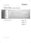
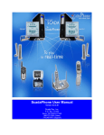
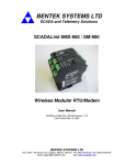
1
BENTEK SYSTEMS LTD
SCADA and Telemetry Solutions
SCADALink 900-MB
Wireless Remote Controller / Radiomodem
USER MANUAL
Version1.2 for SCADALink 900-MB Version 264
BENTEK SYSTEMS LTD
504 - 42 Ave S.E. Calgary, Alberta, Canada T2G 1Y6 Ph: (403) 243-5135 Fax: (403) 243-5165
email: [email protected]
web: www.scadalink.com
TABLE OF CONTENTS
WARNING.........................................................................................................................................................1
COMPLIANCE..................................................................................................................................................2
SCADALINK FEATURES ................................................................................................................................3
SCADALINK TECHNOLOGY .............................................................................................................................3
SCADALINK DATA INTEGRITY .......................................................................................................................3
SCADALINK COMMUNICATIONS....................................................................................................................3
SCADALINK I/O..................................................................................................................................................3
OPERATION.....................................................................................................................................................5
INITIAL SETUP .................................................................................................................................................5
CONFIG 1 ......................................................................................................................................................6
CONFIG 2 ......................................................................................................................................................6
CONFIG 3 ......................................................................................................................................................7
CONFIG 4: .....................................................................................................................................................8
TERMINAL PROGRAMMING...........................................................................................................................9
MODBUS I/O.................................................................................................................................................... 11
SCADALINK MODBUS-RTU Protocol Compatibility ................................................................................... 11
MODBUS Registers ...................................................................................................................................... 12
I/O TERMINAL BLOCK .................................................................................................................................. 14
SERIAL PORTS ................................................................................................................................................ 15
RS232 PORT................................................................................................................................................. 15
RS485 PORT................................................................................................................................................. 15
LED INDICATORS.......................................................................................................................................... 16
RECEIVED SIGNAL STRENGTH INDICATOR (RSSI)............................................................................... 17
ANTENNA SYSTEM AND CONNECTORS ................................................................................................. 18
WARRANTY ................................................................................................................................................... 19
REPRESENTATION....................................................................................................................................... 19
SPECIFICATIONS.......................................................................................................................................... 20
GENERAL ........................................................................................................................................................ 20
RADIO SPECIFICATIONS............................................................................................................................... 20
SERIAL COMMUNICATIONS......................................................................................................................... 20
PARALLEL INPUTS/OUTPUTS....................................................................................................................... 20
APPENDIX A - TECHNICAL NOTES/CONFIGURATION ........................................................................ 21
APPENDIX B - SYSTEM DRAWINGS.......................................................................................................... 23
Bentek Systems Ltd.
Issue V1.2 for SCADALink 900-MB 264
WARNING
WARNING
SCADALink 900-MB radios incorporate a 16-bit address code to give 65,535 different
ID settings, aiding the receiver in identifying the proper transmitter. However, you
should be aware that any other SCADALink 900-MB radio operating in your
vicinity, set to the same ID code, may activate your receiver. While the likelihood
is small, the possibility is real. For this reason each customer system (a network of
SCADALink 900-MBs) will have a unique factory programmed ID code which cannot
be changed by the user. If the customer is using the same ID coded system for
different point-to-point or point-to-multipoint links they should ensure that the
frequency band selection is unique.
Bentek Systems Ltd.
1
Issue V1.2for SCADALink 900-MB 264
COMPLIANCE
COMPLIANCE
This device complies with the requirements of the Federal Communication
Commission (FCC) as specified in document CFR47 Part 15.247 and Industry and
Science Canada (ISC), as specified in document RSS-210. The device is permitted
only on a no-interference no-protection basis, that is, it must cease operation when it
is determined that it causes harmful interference to the services authorized by the
FCC or the ISC.
Changes or modifications not expressly approved by BENTEK SYSTEMS LTD could
void the user’s authority to operate the equipment.
Bentek Systems Ltd.
2
Issue V1.2for SCADALink 900-MB 264
SCADALINK FEATURES
SCADALINK FEATURES
SCADALink TECHNOLOGY
BENTEK SCADALink 900-MB devices employ frequency hopped spread spectrum
technology to provide optimum performance under present FCC and ISC regulations.
These devices are virtually immune to interference since they provide the interference
and range benefits of a narrow band receiver while utilizing the entire 902 - 928 MHz
band. The radio frequency hop pattern is pseudo random in nature and each
frequency is used for 65 msec before hopping to the next one. This hop sequence
repeats approximately every 4 sec.
The SCADALink 900-MB is designed to operate specifically in the 902-928 MHz band.
Many manufacturers have designed their ISM band equipment to operate in an ideal
environment which the unlicensed bands are not. The SCADALink 900-MB radios are
designed to co-exist with all other radios legally allowed in these bands and will
generally outperform most other systems currently available.
Independent frequency groups allow 4 systems to co-exist with no overlap in
frequencies. Many more units can co-exist in one location with a slight penalty in
response time.
SCADALink DATA INTEGRITY
SCADALink 900-MB products are designed for industrial applications. Every effort has
been made to ensure that data over the link is secure and fail-safe. In addition to
CRC-16 error checking, a number of self checking features have been implemented.
A special output on all SCADALink 900-MB transceivers (LINK) indicates the status of
the radio link and provides a fail-safe means of shutting down remote equipment in
the event of a failure in the link.
SCADALink COMMUNICATIONS
The SCADALink 900-MB supports serial communications with either RS-485 or RS232 interfaces. No handshaking is required for serial communications using the
SCADALink 900-MB.
SCADALink I/O
The SCADALink 900-MB has integral I/O (4 inputs and 4 outputs) for remote control
purposes. The I/O can be used in MODBUS RTU slave mode or END to END
Bentek Systems Ltd.
3
Issue V1.2for SCADALink 900-MB 264
SCADALINK FEATURES
Telemetry Mode. In Modbus RTU mode the I/O can be read or written to using
Modbus RTU protocol.
The 4 inputs be used as digital inputs, analog inputs (0-5VDC 8 bit) or pulse counters
with a pulse frequency up to 100 Hz. With optional single channel 15 bit input
adapters each of the input channels can operate as a 15 bit analog input. Different
signal conditioning options are available for the inputs including (0-5VDC, 4-40ma,
TC, RTD) for the input adapters.
The 4 outputs are digital on the base unit. With optional 15 bit analog output adapters
each of 4 outputs can operate as a 15 bit analog output. Different signal conditioning
options are available for the outputs including (0-5VDC, 4-20ma, TC).
Pulse inputs, and I/O adapter modules can only be used with the 204, 214, 234, and
264 versions of the firmware.
Bentek Systems Ltd.
4
Issue V1.2for SCADALink 900-MB 264
OPERATION
OPERATION
INITIAL SETUP
The SCADALink 900-MB can be completely configured using the DIP switches on
the front of the unit. No user programming is required.
The SCADALink can be configured for point to multipoint operations, or in end-toend I/O telemetry mode. See Dwg No. SCADeet1 and Dwg. No. SCADpmp1 in
Appendix A for an overview of the different application configurations.
Configure DIP switches as described in the following section to enable the
appropriate operation.
The diagram below shows the switch designations.
SCADA
LINK
900-MB
CONFIG 1
CONFIG 2
BENTEK
SYSTEMS LTD
CONFIG 3
CONFIG 4
PWR
The following sections describe how to set up the DIP switches in each of 4 switch
banks (config 1 - config 4). All 4 switch banks comprise of 8 bits labeled bit 1 to 8,
starting from the left hand side of the switch bank.
Switch position convention:
ON = UP = 1
OFF = DOWN = 0
Bentek Systems Ltd.
5
Issue V1.2for SCADALink 900-MB 264
OPERATION
CONFIG 1
Bits 1 & 2 select one of four frequency groups. Bits 3 to 6 are factory preset.
CONFIG 1 DIP SWITCH
Freq grp 1
Freq grp 2
Freq grp 3
Freq grp 4
BIT #1
OFF
OFF
ON
ON
BIT #2
OFF
ON
OFF
ON
BITS #3-6
BIT #7
FACTORY
4-20 mA/1-5 V
SET
0-20 mA/0-5 V
BIT #8
SWITCH POSITION
TERMINAL
ON
MODE ACTIVE
REGULAR
OFF
MODE ACTIVE
Bit 7 is used to select between 0-20 mA/ 0-5 V and 4-20 mA/ 1-5 V. After changing
the setting, the power must be cycled for the new setting to take effect.
Bit 8 is used to set the radio in either terminal mode, or regular mode. This bit must
be set “ON” to access terminal programming functions, and must remain set “ON” in
order for those settings to be followed. If Bit 8 is set to “OFF”, the radio’s operating
parameters will only follow the switch settings. If Bit 8 is set to “ON” the radio will
only follow the parameter settings which are programmed into memory using the
terminal.
CONFIG 2
This set of switches configure individual I/O channels for use with the optional single
channel 15 bit analog I/O adapters. (Refer to Dwg No. SCADaip1
And Dwg. No. SCADaop1 in Appendix B for wiring details of I/O adapters)
Setting a correspond bit ON enables the I/O channel to use I/O adapter.
Setting it OFF putting it in regular I/O mode. Following is the channel
correspondance.
Bits 1-4: Correspond to OUT1-4.
Bits 5-8: Correspond to IN1-4.
If the 15 bit analog I/O adapter is not used on a channel, ensure that the
corresponding switch is OFF.
Bentek Systems Ltd.
6
Issue V1.2for SCADALink 900-MB 264
OPERATION
CONFIG 3
LINK TIME-OUT: Selects when a Link Time-out is declared. When Link Time-Out is declared, the
LINK output on the SCADALink 900-MB will go low and all parallel outputs will default to either OFF or
MAINTAIN LAST STATE depending on the condition of the FAIL MODE switch setting. On Point to
Multipoint Mode this LINK output applies only to SLAVE radios. In END to END mode this applies to
both MASTER and SLAVE.
FAIL MODE: On a LINK TIME-OUT, the parallel outputs can be selected to either MAINTAIN LAST
STATE or be turned OFF. In either case, the LINK output will always turn OFF.
PRIMARY PORT: Both RS-232 and RS-485 ports are available on the SCADALINK 900-MB unit.
However only one of the two serial ports may be used for serial communications over the radio. The
remaining port can be used as a local Modbus port to read/write local I/O if a Modbus address is
enabled.
RADIO MODE: In any system, one radio must always be set to RF MASTER mode. All other radios
in the system will be configured as RF SLAVES. RF MASTER and RF SLAVE radios in the same
system must have the same hop sequence id and must be set to the same frequency group. To
synchronize the hopping sequences, the RF SLAVE always derives its timing from the RF MASTER.
RF SLAVE radios can only communicate to the RF MASTER radio, not between themselves.
BUFFER:
TRANSPARENT - Transmission starts as soon as a character is received and continues until
the buffer is clear. Used for file transfer or ASCII based communication protocols.
PACKET - Used for Modbus RTU protocol. Transmission of characters starts after 4
character pause in the data string occurs and continues until the entire packet has been sent.
BIT/PARITY/STOP: Determines the characteristics of both the RS-232 and the RS-485 ports. Radio
transmission characteristics are not affected.
BAUD: 4 user interface baud rates are supported. These baud rates do not affect the radio
transmission rates.
CONFIG 3 DIP SWITCH
BIT #
FUNCTION
1
2
3
4
5
6
LINK TIMEOUT
I/O FAIL MODE
PRIMARY PORT
RADIO MODE
BUFFER
BIT/PARITY/STOP
BIT
MODE
ON
120 sec
DEFAULT OFF
RS-485
RF RADIO MASTER
PACKET
N,8,1
#
SELECT
OFF
10 sec
MAINTAIN LAST STATE
RS-232
RF RADIO SLAVE
TRANSPARENT
E,7,1
BAUD
7
OFF
OFF
ON
ON
8
OFF
ON
OFF
ON
Bentek Systems Ltd.
7
1200
19200
4800
9600
Issue V1.2for SCADALink 900-MB 264
OPERATION
CONFIG 4:
NO MODBUS: In this mode, the SCADALINK acts as a standard packetized radio
modem. The parallel Inputs and Outputs are unused. The Link output is still active.
This configuration permits maximum throughput when used as a serial modem.
MODBUS ADDRESS: Any switch setting for (2-8) other than all 1’s or all 0’s is
treated as a MODBUS RTU address (1-126 are allowable MODBUS addresses).
END-TO-END I/O: The end-to-end configuration enables inputs on the master radio
to be mapped to outputs on the slave radio and inputs on the slave radio to be
mapped to outputs on the master radio. Note: If 15 Bit Analog I/O is used in this
mode, Inputs on one radio must correspond to an output on the other radio. (eg- IN1
on Radio A, OUT1 on Radio B).
FUTURE: Reserved for future expansion.
CONFIG 4 DIP SWITCH
1
OFF
OFF
OFF
2
OFF
OFF
OFF
OFF
ON
OFF
ON
ON
- = Don’t Care
3
OFF
OFF
OFF
4
OFF
OFF
OFF
ON
ON
-
ON
ON
-
Bentek Systems Ltd.
BIT#
5
OFF
OFF
OFF
.
.
.
ON
ON
-
6
OFF
OFF
OFF
7
OFF
OFF
ON
8
OFF
ON
OFF
FUNCTION
NO MODBUS
MODBUS ADDRESS #1
MODBUS ADDRESS #2
ON
ON
-
ON
ON
-
OFF
ON
-
MODBUS ADDRESS #126
END-TO-END I/O
FUTURE
8
Issue V1.2for SCADALink 900-MB 264
OPERATION
TERMINAL PROGRAMMING
Terminal mode is activated by having switch #8 on CONFIG1 up and pressing the
‘ENTER’ key. While in Terminal Mode, both the Rx and Tx LEDs flash
simultaneously. This indicates to the user that the radio may be configured by
computer terminal, rather than by following the switch settings. The radio waits 15
seconds for the ‘ENTER’ key to be pressed. For Instructions on how to connect to the
radio using Terminal Mode, consult the documents in Appendix A.
When switch #8 on CONFIG1 is up, and a 15 second startup has elapsed, the radio
will operate as per the terminal configuration. Setting switch #8 on CONFIG1 down,
lets the switch settings override the terminal programming.
NOTE: FOR radio to make use of terminal settings in memory, CONFIG 1, bit 8
must be “ON”. IF CONFIG1 Bit 8 is down, radio will follow settings from
switches on radio, and ignore settings made in memory.
Advanced Terminal Configuration: This is the highest configuration level available
and offers a table of choices to change the hopping code. The hopping code that is
selected in this menu is stored into memory and is what is used for operation of the
radio, after Terminal mode is exited (regardless of whether switch#8 of CONFIG1 is
set, or not). It also allows the user to enter a new value in the table provided there is
not already 16 values in the table. The user needs a seed value in order for this new
value to be programmed. This value can only be obtained from Bentek Systems Ltd.
Bentek Systems Ltd.
Advanced Terminal Configuration
Choose one of the following codes
<default ID CODE = 3AAA>
(Current Hopping Code of radio) ^^^^
0 : No Change.
1 : 12EE
2 : 23FF
3 : 34AE
4 : 2300
5 : 1900
6 : 0030
7 : 39F5
8 : 033F
9 : 3AFE
A : 0000
B : 3FFF
C : 25FF
D : 3AAA
H : Custom Entry
:
Enter Choice (0-H): 1
•
•
•
Use ‘0’ to make no changes and leave.
Select a listed number/letter for choice.
Use ‘H’ for Custom Hopping Code entry.
Bentek Systems Ltd.
9
Issue V1.2for SCADALink 900-MB 264
OPERATION
Terminal Configuration: This is the lowest configuration level available. Future
functionality features will be made available here.
Bentek Systems Ltd.
Terminal Configuration
No Terminal Configurtion Exists Yet.
Bentek Systems Ltd.
10
Issue V1.2for SCADALink 900-MB 264
OPERATION
MODBUS I/O
The SCADALink 900-MB has 4 inputs (analog, digital, pulse counters, or 15 bit
analog) and 4 outputs (digital or 15 bit analog) channels that can be read or written
using Modbus-RTU protocol. Refer to Modbus I/O Map on the following page for
register mapping.
The SCADALink 900-MB Modbus address can be set to values from 1-126. It will
respond to commands sent over the radio (in RF SLAVE radio mode) or the local
communications channel (in RF MASTER radio mode).
With the address set to 0 the SCADALINK I/O is disabled.
SCADALINK MODBUS-RTU Protocol Compatibility
The SCADALink 900-MB supports a subset of the Modbus RTU protocol. The
following table shows the command codes supported.
SUPPORTED MODBUS COMMANDS
Command
01
02
03
04
05
06
15
16
Bentek Systems Ltd.
Description
Read 000xx register
Read 100xx register
Read 400xx register
Read 300xx register
Write single 000xx register
Write single 400xx register
Write multiple 000xx registers
Write multiple 400xx registers
11
Issue V1.2for SCADALink 900-MB 264
OPERATION
MODBUS Registers
The following tables shows Modbus register mapping for SCADALINK 900MB-264.
01
02
03
04
05
06
07
08
09
10
.
38
39
40
41
42
43
44
45
46
47
48
49
50
51
52
53
54
55
56
57
58
59
60
61
62
63
64
65
66
67
68
69
70
000xx
DOUT1
DOUT2
DOUT3
DOUT4
Bentek Systems Ltd.
MODBUS I/O MAPPING
100xx
300xx
DIN1
IN1
DIN2
IN2
DIN3
IN3
DIN4
IN4
400xx
OUT1
OUT2
OUT3
OUT4
WATCHWRITE
PACKED DOUT1-4
SERIAL NUMBER L
SERIAL NUMBER H
ID1
ID2
CONFIG12
CONFIG34
RSSI - 16 BIT
VOLTAGE - 16 BIT
RSSI - dBm
VOLTAGE - 10ths V
WATCHREAD
PACKED DIN1-16
IN1
IN2
IN3
IN4
COUNTER1 - L
COUNTER1 - H
COUNTER2 - L
COUNTER2 - H
COUNTER3 - L
COUNTER3 - H
COUNTER4 - L
COUNTER4 - H
12
Issue V1.2for SCADALink 900-MB 264
OPERATION
MODBUS I/O SCALING
Signal
IN1-IN4
RSSI
SUPPLY VOLTAGE
WATCHREAD
PACKED DIN1 – 16
PULSE COUNTERS
Bentek Systems Ltd.
Register
30001-30004
40051-40052
40045
40046
40049
40050
40063 - 40070
13
Scaling
0 -32767
Engineering Units
0-5 V
0 -32767
0 -32767
None
None
0 – 65535
0-5V
0-30 V
HEX
HEX
HEX
Issue V1.2for SCADALink 900-MB 264
OPERATION
I/O TERMINAL BLOCK
Refer to Dwg. No. SCADI/O 264B in Appendix B for SCADaLink wiring details.
PWR/GND: The SCADALINK 900-MB will operate at any voltage from +9V to +26V.
The higher the voltage the lower the current as shown in the following graph.
900-M B S U P P L Y V O L T A G E v s C U R R E N T
S L A V E C U R R E N T ( n o t r a n s m i s s ions)
450
M A S T E R C U R R E N T
400
350
CURRENT (mA)
300
250
200
150
100
50
0
8
9
10
11
12
13
14
15
16
17
18
19
20
21
22
23
24
25
VOLTAGE (V))
(D)OUT1-4: These Outputs are open collector type outputs which are each capable
of switching 0.25A. but the combined capacity of all 4 outputs cannot exceed 0.5 A.
The switches have a common ground which is fused at 0.5A. See Appendix B for
typical output wiring. The wiring for I/O adapter modules is also shown in Appendix
B.
The Outputs are used for both Digital (DOUT) and Analog (OUT) Outputs.
(D)IN1-4: These Inputs are high impedance with 100 K pulldowns to ground. See
Appendix B for typical input wiring. A “ON” state for the digital inputs (DIN) or pulse
inputs is sensed whenever the voltage between GND and the input terminal exceeds
2.5 VDC. For dry contact inputs, if the input contact wetted by a +9-26V source
referenced to GND is closed it will show “ON” state, otherwise input is in “OFF”
state. can also Analog inputs (IN) are 0-5V (8bit) DC inputs referenced to GND. The
wiring for I/O adapter modules is also shown in Appendix B.
LINK: This Output indicates that the slave radio is locked onto the master radio and
the communications link is good. It functions electrically like OUT 1-4. If slave radio
looses communication for more than 20 seconds, the output goes “high”. It will
return to pull “low” if communications is restored. A “pull to good” indicates good
communications
SPECIAL: Used for future expansion
Bentek Systems Ltd.
14
Issue V1.2for SCADALink 900-MB 264
OPERATION
SERIAL PORTS
RS232 PORT
The RS-232 port is a 9 pin DB-9 female connector which conforms to DCE
functionality.
5
Gnd
4
2
3
DTR TxD RxD
9
NC
8
CTS
1
DCD
7
6
RTS DSR
RS-232 DCE FUNCTIONALITY
PIN
1
2
3
4
5
6
7
8
9
FUNCTION
DCD
RxD
TxD
DTR
GROUND
DSR
RTS
CTS
Not Used
TYPE
OUTPUT
OUTPUT
INPUT
INPUT
Notes
Follow Link Status
To DCE
From DCE
Not Used
OUTPUT
INPUT
OUTPUT
Always On
Not Used
CTS - OK to send
3 Wire Interface: The RS-232 port can be used in 3 wire mode (TXD, RXD, GND) without
any handshaking.
CTS Handshaking: CTS handshaking can be used for flow control between the DTE and
the SCADALink. On power up, the CTS signal is active, once the buffer is almost full, the
CTS signal is pulled low to signal the DTE to stop transmitting. Generally used for file
transfer operation. SCADALink buffer is 4K.
RS485 PORT
The RS-485 port is a half-duplex port which supports both 2-wire and 4-wire RS-385
communications. The port uses a quick disconnect screw terminal connector.
Tx+ Tx- Rx+ Rx- Gnd
Bentek Systems Ltd.
15
Issue V1.2for SCADALink 900-MB 264
OPERATION
LED INDICATORS
RED STATUS LED:
RF MASTER MODE
SOLID LED indicates the unit is active and is hopping through its
frequency band.
QUICK FLASHING LED (0.5 sec ON, 0.5 sec OFF) indicates low power
supply voltage.
RF SLAVE MODE:
SOLID LED indicates that the unit is locked and tracking a RF MASTER.
SLOW FLASHING LED (1 sec. ON, 1 sec. OFF) indicates the unit is
functioning normally but has not locked onto a RF MASTER.
QUICK FLASHING LED (0.5 sec ON, 0.5 sec OFF) indicates low power
supply voltage.
Note: If SCADALink frequency band is changed, the next time the
SCADALink is powered up it will have to recalculate its hopping sequence.
This takes approximately five seconds during which the STATUS LED will be
off.
GREEN RX LED:
TERMINAL MODE: A constantly flashing Rx LED (flashing simultaneously
with the TX LED) indicates the radio is in Terminal Mode.
REGULAR MODE: Indicates that data is being received over the radio link.
END to END MODE: Alternates in slow flashing sequence with the RX LED.
GREEN TX LED:
TERMINAL MODE: A constantly flashing TX LED (flashing simultaneously
with the RX LED) indicates the radio is in Terminal Mode.
REGULAR MODE: Indicates that the unit is transmitting data over the radio
link.
END to END MODE: Alternates in slow flashing sequence with the RX LED
Bentek Systems Ltd.
16
Issue V1.2for SCADALink 900-MB 264
OPERATION
RECEIVED SIGNAL STRENGTH INDICATOR (RSSI)
SIGNAL STRENGTH: The test point labelled “signal strength” provides a DC
voltage output which gives an indication or the received signal strength. (NOTE:
This output is only meaningful if the SCADALink 900-MB is configured as a
“slave” and is not meaningful if it is configured as a “master”.) This indication is
derived by measuring the signal strength in the channels which it has received error
free. It does not measure the level of signals in channels which have interference
and is therefore a very accurate measurement of signal strength of only the desired
signal over the full 26 MHz operating bandwidth.
To use this output one needs only to connect a dc voltmeter and read the voltage
directly. It can be seen from the graph below, that for signal levels from -100 dBm to
-40 dBm the voltage changes almost exactly 20 dB per volt. At about 2.0 V the
signal strength is approximately -100 dBm. One should generally set up a system
such that the received signal strength is greater than or equal to this level. The
system will still remain operational for an additional 10- dB drop in signal level (1.5
V) to provide a reasonable fade margin.
The following graph can be used to give an approximate correlation of Signal
Strength readings to Receive Signal Strength.
RSSI (SIGNAL STRENGTH)
Signal Strength (-dbm)
110
100
90
Series1
80
70
60
1.5
2
2.5
3
3.5
4
Voltage (V)
NOTE: The RSSI can be read remotely from the master radio if the SCADALink 900-MB is in
Modbus mode.
Bentek Systems Ltd.
17
Issue V1.2for SCADALink 900-MB 264
ANTENNA SYSTEM
ANTENNA SYSTEM AND CONNECTORS
The SCADALINK 900-MB Transceiver comes with a 2 foot long antenna pigtail that
adapts the chassis mount MCX connector to a BNC-Male connector. The user will
connect the antenna feedline via this connector.
The SCADALINK 900-MB Transceiver is supplied from the factory adjusted to 1 Watt
RF output power. This is the maximum transmitter output power allowed under FCC
and ISC regulations.
Regulations limit the effective isotropic radiated power (EIRP) to 6 dBw. The EIRP is
dependent on the transmit output power, the antenna feeder loss, and the antenna
gain. With 1 Watt output power, antenna’s with an isotropic gain of 6 dB are allowed
assuming no feeder cable losses.
The total antenna gain minus the cable loss is not to exceed 6 dBw.
Bentek Systems Ltd.
18
Issue V1.2for SCADALink 900-MB 264
WARRANTY
WARRANTY
All SCADALink 900-MB modules come with a one year limited product warranty to the
original purchaser, covering defects in materials and workmanship under normal use
and service. BENTEK SYSTEMS LTD's entire liability and your exclusive remedy
shall be, at BENTEK option, either the (a) repair or (b) replacement of the SCADALink
900-MB module, which is returned to BENTEK SYSTEMS LTD freight prepaid with a
copy of the purchase receipt. If failure has resulted from accident, abuse or
misapplication, BENTEK SYSTEMS LTD shall have no obligation to repair or replace.
In no event shall BENTEK SYSTEMS LTD be responsible for incidental or
consequential damage caused by defects in its products, whether such damage
occurs or is discovered before or after replacement or repair, and whether or not such
damage is caused by the negligence of BENTEK SYSTEMS LTD.
REPRESENTATION
BENTEK SYSTEMS LTD makes no representation or warranties with respect to this
manual, or, except as specifically stated in the applicable user agreement or warranty
notice, with respect to any hardware, firmware, or software described in this manual.
BENTEK SYSTEMS LTD specifically disclaims any express or implied warranties of
merchantability, title, or fitness for any particular purpose. The information contained
in this document is assumed to be correct and current. BENTEK SYSTEMS LTD
reserves the right to make revisions or changes to any and all parts of the manual,
hardware, firmware, or software at any time without obligation to notify any person or
entity of the changes.
Bentek Systems Ltd.
19
Issue V1.2for SCADALink 900-MB 264
SPECIFICATIONS
SPECIFICATIONS
GENERAL
Power:
Voltage
Current Rx
Current (Maximum)
Temperature Range:
Operating
Storage
Length
Width
Height
Mounting
Material
9-26 VDC
60 mA @ 12V; 40 mA @ 24V
250 mA @12V; 145 mA @24 V
(assumes Continuous operation in MASTER mode)
Size: Max dimensions
Case:
Weight:
-40 to +60 C
-55 to +90 C
5”
3.75”
1.5”
4 x 5/32’’ Dia. mounting holes (Fits #8 Screws)
.06” Anodized Aluminum 2 Pcs.
9.2 Oz. (960 grams)
RADIO SPECIFICATIONS
Technique
Frequency
Hop Sequence Length
Available Sequences
Available ID Codes
Frequency Bands
Hop Dwell Time
Transmit Power
Rx Sensitivity
Error Detection
Error Correction
Typical Range
Frequency Hopping
902-928 MHz
63
255
65535
4 Interleaved
65 ms
1 Watt
<-110 dBm to maintain synchronization
CRC-16
Auto Packet Repeat
2 km with Omni Directional Antennas
5 km+ with Yagi antennas
SERIAL COMMUNICATIONS
Interface:
Data Rates:
Data Format:
Flow Control:
Bit Error Rates
Protocol
RS-232 (9 pin DB-9 Female DCE standard)
RS-485 (2 Wire or 4 Wire Half Duplex)
1200,4800,9600,19200
Asynchronous - N,8,1 or E,7,1
RTS/CTS or None
10e-6 BER at -104 dBm without error correction
Modbus RTU
PARALLEL INPUTS/OUTPUTS
Interface:
Base I/O:
Inputs DI/AI
Outputs DO
Link Status
Special
Bentek Systems Ltd.
Quick-disconnect screw terminal
4 - Analog/Discrete inputs
Discrete - 0 - 26 V
Analog - 0 - 5 V DC (8 bit accuracy)
Pulse Counters - 100 Hz Maximum
4 - Open Collector to GND.
0.25 Amp each
Open Collector to GND.
Reserved for future expansion
20
Issue V1.2for SCADALink 900-MB 264
SYSTEM DRAWINGS
APPENDIX A - TECHNICAL NOTES/CONFIGURATION
Hyperterminal Settings for Use with SCADALink 900MB Terminal
Mode
1. Select Start->Programs->Accessories->Hyperterminal
2. Run Hypertrm.exe.
3. Choose an icon and make a name called SCADALINK, Click OK.
4. Click ‘Connect using:’
5. Select DIRECTtoCom1 or whichever Com Port you wish to use, Click OK.
6. Click the ‘Configure’ Button.
7. Set Bits per Second to 9600.
8. Set Data Bits to 8.
9. Set Parity to None.
10. Set Stop Bits to 1.
11. Set Flow Control to Hardware.
12. Click OK.
13. Click OK.
14. Save settings
15. You now have an icon in Hyperterminal called SCADALINK.ht that sets up your
Com Port to communicate to the radio.
16. Next time, just double click on the SCADALINK.ht icon you just created.
Using these settings on Hyperterminal, you can access the terminal programming part
of the radio. If you choose to use a different terminal emulation software package,
please use the following settings:
Terminal Emulation:VT100
Baud Rate:
9600
Data Bits:
8
Parity:
None
Stop Bits:
1
Bentek Systems Ltd.
21
Issue V1.2for SCADALink 900-MB 264
SYSTEM DRAWINGS
Hardware Setup for Use with SCADALink 900MB Terminal Mode
1.
2.
3.
4.
Connect the computer to the radio’s RS-232 port.
Put Switch 8 on CONFIG1 in the ‘up’ position.
Turn radio on. The Tx and Rx LEDs should flash simultaneously.
You have 15 seconds to press the ‘ENTER’ key before the radio returns to regular
mode.
Bentek Systems Ltd.
22
Issue V1.2for SCADALink 900-MB 264
SYSTEM DRAWINGS
APPENDIX B - SYSTEM DRAWINGS
Bentek Systems Ltd.
23
Issue V1.2for SCADALink 900-MB 264