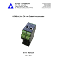
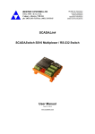
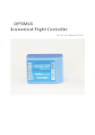
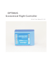
1
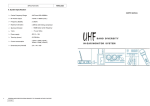
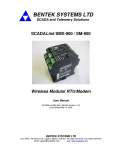
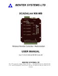
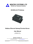
BENTEK SYSTEMS LTD
SCADA and Telemetry Solutions
SCADALink IO900
Modular Wireless I/O System
User Manual
Version V1.3 for SCADALink IO900
BENTEK SYSTEMS LTD
#315, 3750- 46 Ave S.E. Calgary, AB, Canada T2B 0L1 Ph:(403)243-5135 Fax:(403)243-5165
email: [email protected]
web: www.scadalink.com
BENTEK SYSTEMS LTD
SCADA and Telemetry Solutions
SCADALink IO900
The SCADALink IO900 is a Modular Wireless I/O System that allow license free bidirectional transmission of digital and analog process signals at distances of up to 20+
miles. The IO900 System is a simple to use modular system that allows addition of up to
8 I/O Expansion Modules to the base IO900 Controller which has 1 AI, 1 AO, 2 DI, and 2
DO points.
Ÿ
Ÿ
Ÿ
Ÿ
Ÿ
Ÿ
Ÿ
Ÿ
License Free 900MHz
20+ Mile Range
Secure Factory Set RF Configuration
12-30VDC Operation
Class I Div II
DIN Rail Mounted Modules
Modular Expansion to 8 I/O Modules
Modules
IO900 Controller 1 AI, 1 AO, 2 DI, 2 DO
AI4 Module - 4 Pt 4-20ma Input Module
AO4 Module 4 Pt 4-20ma Output Module
DI8 Module - 8 Pt Digital Input Module
DO8 Module - 8 Pt Digital Output Module
Typical Application
1AO
2DO
1AO
2DO
Bentek Systems Ltd.
DI8
Module
8 DO
I/O 900 with 1 AO,
1DIModule
AO4
Module
4AI
I/O 900 with 1
AI, 1DO Module
IO900
DO8
Module
1AI
2DI
AI4
Module
IO900
I/O is Mirrored Up to 20+ Miles
1AI
2DI
4AO
8 DI
Version V1.03 for SCADALink IO900
BENTEK SYSTEMS LTD
SCADALink IO900
SCADA and Telemetry Solutions
IO900 Transceiver
Analog and Discrete Input Wiring
+24VDC
+24VDC
Current
Source
4-20mA Device
Current
Source
+
A
B
RF Link
GND PWR
4-20mA Device
+
-
Power
A
B
RF Link
Floating
+
-
+
OUT
Signal
IN
Floating
+
-
+
-
OUT
STATUS
IN
4-20mA
IN1
www.scadalink.com
RSSI
IO900
SCADALink
www.scadalink.com
SCADALink
STATUS
Discrete
IN2
1B
2A
OUT1
1B
IN1
1A
OUT2
2A
RSSI
IO900
Discrete
2B
Discrete
1A
Power
-
4-20mA
1A
GND PWR
2B
IN2
1B
2A
2B
Discrete
OUT1
1A
1B
OUT2
2A
2B
+24VDC
Discrete
Input 1
Discrete
Input 2
2 Wire 4-20mA Device
Bentek Systems Ltd.
3 Wire 4-20mA Device
Version V1.03 for SCADALink IO900
BENTEK SYSTEMS LTD
SCADALink IO900
SCADA and Telemetry Solutions
IO900 Transceiver
Analog and Discrete Output Wiring
Link Status Indicator
+24VDC
RF Link Output
The Link Status contact on the IO900 is Normally
Open and closes when the radio establishes an
RF Link. It can be used to switch either a STATUS
light or a FAULT indicator.
Selecting State of Outputs upon Loss of RF Link
Analog
Output
4-20mA
A
-
B
GND PWR
RF Link
Power
+
+
The default state upon loss of RF signal for the
Analog and Discrete Outputs is MAINTAIN LAST
STATE. They may be wired in series with the RF
Link contact to provide a FAULT OFF when RF
Link is terminated.
+
OUT
IN
4-20mA
STATUS
www.scadalink.com
SCADALink
RSSI
IO900
Discrete
IN1
1A
IN2
1B
2A
2B
Discrete
OUT1
1A
1B
OUT2
2A
2B
Supressor
M
Power Supply
120VAC 5A
Max
Bentek Systems Ltd.
Version V1.03 for SCADALink IO900
BENTEK SYSTEMS LTD
SCADA and Telemetry Solutions
SCADALink IO900
Specifications
IO900 Transceiver
General
Range
Inputs
Outputs
I/O Expansion Capability
Repeatability
Accuracy
Wiring Connections
Mounting
Primary Power
Input Voltage
Reverse Polarity Protection
Surge Protection
Power Consumption
Transceiver
Frequency
Transmit Power
RX Sensitivity
Unit ID
Antenna Connector
Antenna Impedance
Environmental
Humidity
Temperature
Size
Weight
Enclosure
Agency Approvals
FCC
ISC
600 to 1000 feet (180 to 305m) in-plant [obstructed]; 4-5 miles (6-8km) LOS
with Omni antenna; 20+ miles (32+km) LOS with Yagi antenna
One (1) 4-20mA analog input 16-bit, 125 ohms impedance)
Two (2) discrete inputs (5-36VDC)
One (1) 4-20mA analog output (16-bit, short-circuit protected)
Two (2) discrete outputs (dry contact, NO, contact rating: 120VAC/2A;
12VDC/2A; 24VDC2A)
Eight (8) analog and/or discrete I/O cards
Current loop: 0.02%
Current loop: 0.2% of full-scale @ 77°F (25°C)
12-24 AWG screw-type terminals; removable terminal blocks
DIN rail mount
9 to 30VDC
Yes
Yes
110mA (average) / 170mA (peak) @ 24VDC during transmission (plus I/O modules)
902 to 928MHz - ISM band
1 Watt (30dBm)
-105dBm
16 bit unique (factory configured); Allows multiple units in same area
MCX female
50 ohms
20% - 90% (non-condensing)
Operating: -40°F to 158°F (-40°C to 70°C)
4.5” x 3.9” x 0.9” (114mm x 99mm x 23mm)
5.3 oz (150 g)
NEMA 1 (equivalent to IP30)
Part 15.247
RSS 210
FCC Rules and Compliance
This device complies with Part 15 of the FCC Rules. Operation is subject to the following two conditions: (1) This device
may not cause harmful interference, and (2) this device must accept any interference received, including interference that
may cause undesired operation.
Changes or modifications not expressly approved by BENTEK SYSTEMS LTD will void the user's authority to operate the
equipment.
This product is intended for fixed installation applications. In order to comply with FCC/ISC adopted RF exposure
requirements, installation of this transmitter system's antennas must be performed in a manner that will provide at least 6
foot(2m) clearance from the front radiating aperture to any user or member of the public.
FCC
ISC
CSA/C & US
Part 15.247
Approval# IA9FHOEM900
RSS 210
Approval# 1338104550A
Class 1 Div 2 (Groups A,B, C,D)
Bentek Systems Ltd.
Version V1.03 for SCADALink IO900
BENTEK SYSTEMS LTD
SCADALink IO900
SCADA and Telemetry Solutions
Configuring I/O Module Addresses
5
5
4
4
5
4
6
3
7
1
8
4
3
7
2
1
5
6
3
3
2
5
6
6
7
7
2
8
2
4
1
6
3
7
2
8
8
1
8
1
Module Address Selection Switch
Each pair of I/O modules, such as the AI4 and the AO4, must share
a unique module address. Once a module address has been
assigned to a pair of I/O modules, that module address may not be
used on any other pair of I/O modules or the same radio pair.
Available addresses are numbers 1 through 8. If module addresses
conflict, or are improperly set within a connected group, an indication
will be given by the STATUS LED (see section below).
The IO900 Transceivers are designed to operate as matched pairs,
and are factory programmed. Manual address configuration is not
required for the transceiver units.
Status LED's
Power LED
Power LED indicates presence of power to the device. It is ON when power is present and OFF when there is no power.
Status LED
When flashing rapidly it indicates an "Internal Error" or a "Module Type Mismatch"
A Module Type Mismatch occurs when the Module Address selection for two different modules (i.e. one (1) discrete module
and one (1) analog module) are set to the same address, or two (2) pairs of modules are sharing the same address.
When Status LED is ON steady, Module Address settings are OK.
RF LED
- Flashes once every two seconds when there is no RF Link
- Flashes rapidly when signal strength is marginal (see RSSI Table)
- ON steady indicates an exceptionally strong RF Link.
- Most systems will flash occasionally indicating the presence of intermittent interference in the area
Discrete
Input / Output
OFF means that the discrete input or output is Open
ON means that the discrete input or output is Closed
RSSI Troubleshooting
RSSI vs DC Voltage
The following RSSI table may be used to test the Receive Signal Strength of
the IO900.
The ideal voltage that should be read from the RSSI test point is 2.5VDC.
This represents a -90dB signal loss and typically indicates that the radio has
20dB fade margin left until loss of link. It is recommended that the radios be
set up with no less than 20dB margin.
Bentek Systems Ltd.
4.00
3.00
+DC Volts
RSSI (Received Signal Strength Indicator) is measured using a DC
Voltmeter between the test point and power supply ground. Test point is
accessed by inserting positive meter probe into the RSSI hole on the face of
the IO900.
2.00
1.00
0.00
-120
-110
-100
-90
-80
-70
Signal Loss (-dB)
Version V1.03 for SCADALink IO900
-60
BENTEK SYSTEMS LTD
SCADALink IO900
SCADA and Telemetry Solutions
Expansion I/O Modules
Analog Input/Output Wiring
4-20mA Device
Current +
Source -
+
-
Analog
Output
4-20mA
Floating
GND P+
Current
Source
-
+
4-20mA Loop
IN 1
4-20mA Device
GND P+
-
GND P+
GND P+
+
4-20mA Loop
IN 2
+
-
P+ GND
+
-
-
P+ GND
+
AO4
4-20mA Loop
OUT 3
+
-
P+ GND
4-20mA Loop
OUT 4
4
4-20mA Loop
IN 4
ON
+
Last State
3
4-20mA Device
Source
+
2
External
Voltage
Maintain
Off
1
4-20mA Loop
IN 3
Fault
www.scadalink.com
DIP Switch
Settings
AI4
-
STATUS
SCADALink
Floating
SCADALink
www.scadalink.com
Signal
+
4-20mA Loop
OUT 2
STATUS
-
-
4-20mA Loop
OUT 1
By removing the housing of the AO4
module, the end user may select
between "Fault Off" or "Maintain
+
-
P+ GND
Last State" for each of the four
analog outputs of the AO4 Module
Floating
AI4 - Expansion Analog Input Module
Bentek Systems Ltd.
AO4 - Expansion Analog Output Module
Version V1.03 for SCADALink IO900
BENTEK SYSTEMS LTD
SCADALink IO900
SCADA and Telemetry Solutions
Expansion I/O Modules
Discrete Input/Output Wiring
Liquid Level
Fault Contact
+
DIP Switch
Settings
-
Fault
Off
+
Maintain
Last State
ON
1
-
Pressure
1A
1B
2A
2B
IN 1
IN 2
Discrete
2
Fault Contact
3A
3B
4A
4B
3
4
+
1B
2A
2B
STATUS
7
3A
3B
4A
4B
8
IN 3
IN 4
Discrete
By removing the housing of the DO8
module, the end user may select
between "Fault Off" or "Maintain
Last State" for each of the eight
STATUS
SCADALink
www.scadalink.com
discrete outputs of the DO8 Module
Supressor
SCADALink
www.scadalink.com
IN 1
IN 2
Discrete
6
Temperature
Fault Contact
5
1A
-
IN 3
IN 4
Discrete
5A
5B
6A
6B
Discrete
IN 7
IN 8
7A
DI8
DO8
Discrete
IN 5
IN 6
7B
7A
7B
Discrete
IN 5
IN 6
Solid State
Switch
5A
5B
6A
6B
Discrete
IN 7
IN 8
7A
7B
7A
7B
Power Supply
100VAC/DC
M
Power Supply
120VAC 5A
Max
Max
DI8 - Expansion Discrete Input Module
Bentek Systems Ltd.
DO8 - Expansion Discrete Output Module
Version V1.03 for SCADALink IO900
BENTEK SYSTEMS LTD
SCADA and Telemetry Solutions
SCADALink IO900
Specifications
I/O Expansion Modules
DI8 - Discrete Input Module – Low Volt
Channels
Input Voltage Range
Input Impedance
Optically Isolated
Reverse Polarity Protected
Over-Voltage Rating
Power Consumption
Channels
Output Terminals
Contact Ratings
Power Consumption
Channels
Resolution
Input Impedance
Reverse Polarity Protected
Over-Voltage Rating
Accuracy
Power Consumption
Channels
Resolution
Short-Circuit Protection
Optically Isolated
Accuracy
Power Consumption
Eight (8)
5 to 36VAC/DC
5K ohms
Yes
Yes
100VAC/DC max.
26mA
DO8 - Discrete Output Module – 8 Ch, Relay
Eight (8)
Dry contact (NO)
120VAC/2A 220VAC/2A 12VDC/2A 24VDC/2A
10mA @ 24VDC (outputs OFF); 60mA @ 24VDC (outputs ON)
AI4 - 4-20mA Analog Input Module – 4 Ch
Four (4)
16-bit
125 ohms
Yes
42VDC max.
0.2%
30mA (inputs disconnected)
AO4 - 4-20mA Analog Output Module – 4 Ch, ISOL
Four (4)
16-bit
Yes
Yes
0.12%
25mA (outputs disconnected)
Warranty
BENTEK SYSTEMS LTD warrants to the original purchaser that the BENTEK products are free from defects in materials
and workmanship under normal use and service for a period of ONE YEAR, parts (EXLUDING: SWITCHES, CRYSTALS,
OR PARTS SUBJECT TO UNAUTHORIZED REPAIR OR MODIFICATION) and labor from the date of delivery as
evidenced by a copy of the receipt.
BENTEK's entire liability and your exclusive remedy shall be, at BENTEK's option, either the (a) repair or (b) the
replacement of the BENTEK product which is returned within the warranty period to BENTEK, freight collect by a BENTEK
APPROVED carrier with a copy of the purchase receipt and with the return authorization of BENTEK.
If failure has resulted from accident, abuse or misapplication, BENTEK shall have no responsibilty to repair or replace the
product under warranty.
In no event shall BENTEK be responsible for incidental or consequential damage caused by defects in its products,
whether such damage occurs or is discovered before or after replacement or repair and whether or not such damage is
caused by the negligence of BENTEK SYSTEMS LTD.
Bentek Systems Ltd.
Version V1.03 for SCADALink IO900