1
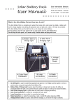
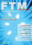
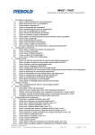
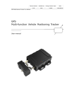
UM10384
UBA2028 CFL 18 W, 230 V dimmable reference board
Rev. 03 — 20 July 2010
User manual
Document information
Info
Content
Keywords
UBA2028, CFL, TRIAC dimmable, charge pump
Abstract
This document is a user manual for the 18 W, 230 V mains dimmable CFL
reference board based on the NXP Semiconductors UBA2028.
UM10384
NXP Semiconductors
230 V dimmable reference board
Revision history
Rev
Date
Description
03
20100720
Third issue. Modifications:
•
•
All illustrations updated to revised AQL standard.
Section 10 “Legal information” updated.
02
20100215
Second issue
01
20091014
First issue
Contact information
For more information, please visit: http://www.nxp.com
For sales office addresses, please send an email to: [email protected]
UM10384
User manual
All information provided in this document is subject to legal disclaimers.
Rev. 03 — 20 July 2010
© NXP B.V. 2010. All rights reserved.
2 of 15
UM10384
NXP Semiconductors
230 V dimmable reference board
1. Introduction
WARNING
Lethal voltage and fire ignition hazard
The non-insulated high voltages that are present when operating this product, constitute a
risk of electric shock, personal injury, death and/or ignition of fire.
This product is intended for evaluation purposes only. It shall be operated in a designated test
area by personnel that is qualified according to local requirements and labor laws to work with
non-insulated mains voltages and high-voltage circuits. This product shall never be operated
unattended.
The UBA2028 230 V mains dimmable reference board is a Compact Fluorescent Lamp
(CFL) driver for a 18 W CFL burner. The maximum input power is 18 W, and it can be
dimmed using a TRIAC dimmer. The dimming range reaches down to 10 % of light output.
2. Features
2.1 IC description
UBA2028 is a monolithic integrated circuit for driving electronically ballasted fluorescent
lamps. The circuit is made in a 650 V Bipolar CMOS DMOS (BCD) power-logic process. It
provides the drive function for the two discrete power MOSFETs. Besides the drive
function, the IC also includes the level-shift circuit, the oscillator function, a lamp voltage
monitor, a current control function, a timer function and protections.
The IC includes:
•
•
•
•
•
•
•
•
•
Adjustable preheat time.
Adjustable preheat current.
Current controlled operating.
Single ignition attempt.
Adaptive non-overlap time control.
Integrated high voltage level-shift function.
Power-down function.
Protection against lamp failures or lamp removal.
Capacitive mode protection.
2.2 Board description
2.2.1 Specification
This user manual describes the design of a 230 V mains dimmable CFL ballast solution
that may be employed in an already existing TRIAC based incandescent dimmer setup.
The disadvantage of normal electronic ballasts is that they cannot be dimmed with a
standard phase cut type of dimmer.
UM10384
User manual
All information provided in this document is subject to legal disclaimers.
Rev. 03 — 20 July 2010
© NXP B.V. 2010. All rights reserved.
3 of 15
UM10384
NXP Semiconductors
230 V dimmable reference board
This is because in TRIAC dimming, not only does the lamp current vary based on the
TRIAC position but also the supply voltage variation. Typically the TRIAC conducts once it
has been triggered and exceeds its latching current. and does not conduct when the
current is less than the holding current. The dimmer works fine with a resistive load, such
as an incandescent lamp. The TRIAC can be triggered at any timing of the sinusoidal
voltage (AC line input), and can be kept in conduction state until it reaches zero line
voltage.
The dimmer solution is based on the UBA2028, which can be designed into a ballast
application such that the load is dimmable with a standard (phase cut) type of dimmer.
The board is designed to drive a 18 W CFL burner for 230 V (AC) mains input. The
230 V (AC) reference board, it consists of an AC mains input filter, a rectifier, a TRIAC
dimmer position detector, the lamp current detector, half-bridge resonant tank and the
charge pump circuit.
UM10384
User manual
All information provided in this document is subject to legal disclaimers.
Rev. 03 — 20 July 2010
© NXP B.V. 2010. All rights reserved.
4 of 15
UM10384
NXP Semiconductors
230 V dimmable reference board
3. Circuit diagram
The circuit diagram is shown in Figure 1
C21
1 nF
1000 V
R8
R10
560 kΩ
560 kΩ
R16
200 kΩ
D3
D4
FR107
FR107
C6
100 nF
L3
C8
CD1
10 μF,
400 V
R1
220 kΩ
HV
FS
FS
GND
R2
220 kΩ
ACM
LVS
R14
C4
4.7 μF
D2
D8
R6
5.1 V
IN4148
33 kΩ
R3
24 kΩ
R4
22 kΩ
R5
33 kΩ
3 MΩ
VREF
CSP
CSN
C7
4.7 μF
CT
1
20
2
19
3
18
4
17
5
UBA2028
16
6
15
7
14
8
13
9
12
10
11
SL
C14
1 nF,
1000 V
D5
1N4148
GLI
PCS
C15
1 nF
D9
12 V
IN4007
D1b
D1d
D1c
47 nF,
400 V
C16
3.9 nF,
1000 V
SH
VDD
GLO
R9
1.5 Ω,
2W
L3A
1.8 μH
R15
2.4 Ω
L3B
1.8 μH
C18
220 nF
100 V
C19
220 nF
100 V
GND
IREF
EF20-CFL
CF
CSW
C10
220 nF
D1a
C17
2.5 mH
100 nF
R7
33 kΩ
C9
220 nF
R16
1 kΩ
C12
10 nF
C11
100 pF
D7
R13
CX1
1 kΩ
47 nF, 400 V
C22
470 pF
L1
6.8 mH
CX2
47 nF 400 V
Dc
IN4148
Rc1
Rc
15 Ω, 1 W
15 Ω, 1 W
FR107
C20
470 nF
D6
FR107
R11
4.7 Ω, 1W
L
230 V AC
N
014aaa917
Fig 1.
UBA2028 230 V (AC) circuit diagram
UM10384
User manual
All information provided in this document is subject to legal disclaimers.
Rev. 03 — 20 July 2010
© NXP B.V. 2010. All rights reserved.
5 of 15
UM10384
NXP Semiconductors
230 V dimmable reference board
4. Board connection
The 230 V (AC) mains input connection and four CFL connections for the burner is
connected as shown in Figure 2. A resistor of 4.7 Ω is placed in series with the 230 V
mains input.
230 V AC
CFL
019aaa330
Fig 2.
230 V (AC) version of UBA2028 mains dimmable CFL reference board
The 230 V (AC) mains dimmable CFL reference board based on the UBA 2028 consists of
both main and plug-in boards. The plug-in board can either be connected to the main
board by a socket connector, or can be soldered directly.
The AC mains input and burner connections are indicated in Figure 1.
5. Circuit considerations
5.1 Preheat time selection
Preheat time can be adjusted by the capacitor C9 (CT pin) and the resistor R7 (IREF pin).
R7 could be selected between:
2.5 V / 65 μA = 38 kΩ and 2.5 V / 95 μA = 26 kΩ (the values 65 μA and 95 μA refer to the
UBA2028 data sheet). Usually R7 is selected to be 33 kΩ.
Because R7 also defines fmin, it is advised to change C9 to adjust the preheat time. The
preheat time equation is as follows:
C9
R7
- × -------------------------s
T pr = -----------------------------–9
3
( 330 × 10 ) ( 33 × 10 )
UM10384
User manual
All information provided in this document is subject to legal disclaimers.
Rev. 03 — 20 July 2010
© NXP B.V. 2010. All rights reserved.
6 of 15
UM10384
NXP Semiconductors
230 V dimmable reference board
5.2 Preheat current selection
Preheat current can be adjusted by L3A, L3B, C19, C18 and R9. Reducing the value of
R9 will increase filament preheat current, vice versa. For good ignition, it is recommended
t to maintain lamp preheat current according to the lamp specification. The number of
turns in the auxiliary cathode inductor windings of the output inductor L3 should be chosen
to provide sufficient preheat. The lamp filament (cathode) resistance over the range of
dimming levels must be between 3 times and 5.5 times the resistance when cold.
5.3 Transformer selection
The transformer L3 for a dimmable application needs to supply enough current during low
light output to maintain a constant mains derived DC voltage. The primary inductance is
designed to allow a high peak ignition current without saturation. To minimize losses in the
inductor multi-stranded wire should be used in combination with ferrite cores of sufficiently
good quality. For this reference board, the primary inductance is 2.5 mH, and the
secondary inductance, used for inductive preheating is 1.8 μH. A simplification for
inductor selection would be, for a lamp with a 10% higher power, simply reduce the coil
value by 10%.
5.4 Charge pump and feedback capacitor selection
The charge pump capacitor is important for CFL dimming, without the charge pump
capacitor the lamp could not be dimmed, the charge pump has two function: one is to
pump power to the electrical capacitance at low dimming positions to prevent capacitive
mode, another is to draw current from the dimmer, even for voltages approaching the zero
crossing level as this is needed to maintain the hold current for TRIAC operation.
5.5 Input filter selection
Input filter components CX2, CX1 and L1 need select to filter output noise of dimmer to
supply a smooth voltage to CSP pin, also it needs avoid resonance of dimmer and the
system during whole dimming range. The input filter also need avoid EMI to interference
the input power supply.
5.6 Burner filament current selection when a low light output is required
During low light output, because of very low current through burner, the filament
temperature will go down. Under this condition, the electron emission temperature will not
be enough, and not enough electrons will be emitted. So L3A, L3B, C19 and C18 need to
support enough current (normally around 200 mA RMS) to the filament, in order to
maintain filament temperature during low light output.
UM10384
User manual
All information provided in this document is subject to legal disclaimers.
Rev. 03 — 20 July 2010
© NXP B.V. 2010. All rights reserved.
7 of 15
UM10384
NXP Semiconductors
230 V dimmable reference board
6. Measurements
Table 1.
Dimming measurements using Norma D4000 power analyzer
Norma analyzer measurement
UBA2028 (no dimming)
UBA2028 (minimum dimming)
VI (V RMS)
230
100
II (mA RMS)
155
105
PACT (W)
22
7
CFi
4.2
9
TDI
0.77
0.92
PF
0.62
0.65
For the UBA2028 with no dimming measurements, the Norma D4000 power analyzer was
placed between the lamp and the mains and no TRIAC dimmer was used.
For the UBA2028 minimum dimming measurements, the Norma D4000 power analyzer
was placed between the TRIAC dimmer and the lamp in order to measure PACT at
minimum dimming level.
019aaa327
Fig 3.
EMI measurement
UM10384
User manual
All information provided in this document is subject to legal disclaimers.
Rev. 03 — 20 July 2010
© NXP B.V. 2010. All rights reserved.
8 of 15
UM10384
NXP Semiconductors
230 V dimmable reference board
6.1 I-transformer and V-burner under maximum and minimum light
output
For dimmable applications, the burner selection is very important. When the burner is
adjusted to a low light output, the burner voltage will go high, and the main voltage will go
down due to the action of the TRIAC. Under these conditions, the resonant inductance
needs a support current in order to maintain a smooth main DC voltage for the high
voltage burner. When the high light output and the burner voltage change is not excessive
when dimming to a low light output, the burner should have a voltage of approximately
100 V.
Figure 4 and Figure 5 show the measured waves of the I-transformer and V-burner with a
suitable burner, under maximum and minimum light outputs. From these results, a small
voltage change of the burner can be seen, and as the transformer current is less, the
MOSFET will not be overloaded.
019aaa328
Fig 4.
I-transformer and V-burner under maximum light output
UM10384
User manual
All information provided in this document is subject to legal disclaimers.
Rev. 03 — 20 July 2010
© NXP B.V. 2010. All rights reserved.
9 of 15
UM10384
NXP Semiconductors
230 V dimmable reference board
019aaa329
Fig 5.
I-transformer and V-burner under minimum light output
7. Transformer specification
Figure 6 shows the transformer schematic:
Transformer
bottom view
4
5
3
2
6
L3A
1
L3B
L3
7
8
019aaa331
L3 = 2.5 mH
L3A = 1.8 μH
L3B = 1.8 μH
Fig 6.
Transformer schematic
7.1 Electrical characteristics
Table 2.
UM10384
User manual
Inductance
Section
Inductance
Resistor
Primary
2.5 mH
7Ω
Secondary
1.8 μH
180 mΩ
All information provided in this document is subject to legal disclaimers.
Rev. 03 — 20 July 2010
© NXP B.V. 2010. All rights reserved.
10 of 15
UM10384
NXP Semiconductors
230 V dimmable reference board
7.2 Core and bobbin
• Core size: EF20
• Core material: Philips 3C85, Siemens N27 or equivalent
• Gap length: 1.0 mm
8. Bill Of Materials (BOM)
The components used for the reference board are given in Table 3
Table 3.
BOM
Designator
Part type
Description
Remarks
R11
4.7 Ω; 1 W fusistor
fusistor resistor
fusistor
CD1
10 μF; 400 V
electrical capacitance
high temperature electrical
105 °C
C21
1 nF; 1000 V
capacitance
charge pump capacitor
CX1
47 nF; 400 V
CBB capacitance
CX2
47 nF; 400 V
CBB capacitance
C17
47 nF; 400 V
CBB capacitance
C16
3.9 nF; 1000 V
CBB capacitance
L1
6.8 mH; R = 12 Ω
filter inductor
L3
2.5 mH
lamp inductor
EF20 core
L3A
1.8 μH
filament preheat inductor
EF20 core
L3B
1.8 μH
filament preheat inductor
EF20 core
D1a to D1d
1N4007
diode
D3
FR107
diode
D4
FR107
diode
D6
FR107
diode
D7
FR107
diode
R1
220 KΩ
resistor
R2
220 KΩ
resistor
R3
24 KΩ
resistor
R4
22 KΩ
resistor
R5
33 KΩ
resistor
R6
33 KΩ
resistor
R7
33 KΩ
resistor
R8
560 KΩ
resistor
R9
1.5 Ω; 2 W
resistor
R10
560 KΩ
resistor
R13
1 KΩ
resistor
R14
3 MΩ
resistor
R15
2.4 Ω
resistor
R16
1 KΩ
resistor
SMD components
UM10384
User manual
All information provided in this document is subject to legal disclaimers.
Rev. 03 — 20 July 2010
connected to pin CSW
© NXP B.V. 2010. All rights reserved.
11 of 15
UM10384
NXP Semiconductors
230 V dimmable reference board
Table 3.
UM10384
User manual
BOM …continued
Designator
Part type
Description
Remarks
R16
200 KΩ
resistor
connected to pin 16
Rc
15 Ω; 1 W
resistor
Rc1
15 Ω; 1 W
resistor
C4
4.7 μF; 50 V
capacitor
C6
100 nF; 50 V
capacitor
C7
4.7 μF; 50 V
capacitor
C8
100 nF; 50 V
capacitor
C9
220 nF; 50 V
capacitor
C10
220 nF; 50 V
capacitor
C11
100 pF; 50 V
capacitor
C12
10 nF; 100 V
capacitor
C14
1 nF; 1 kV
capacitor
C15
1 nF; 50 V
capacitor
C18
220 nF 100 V
capacitor
C19
220 nF; 100 V
capacitor
C20
470 nF; 50 V
capacitor
C22
470 pF; 50 V
capacitor
D2
BZV55; 5.1 V
Zener diode
D5
1N4148
diode
D8
1N4148
diode
D9
BZV55; 12 V
Zener diode
Dc
1N4148
diode
-
EF20 CFL; 18 W,
I50 V RMS
EFL
-
UBA2028T
IC
All information provided in this document is subject to legal disclaimers.
Rev. 03 — 20 July 2010
NXP Semiconductors
© NXP B.V. 2010. All rights reserved.
12 of 15
UM10384
NXP Semiconductors
230 V dimmable reference board
9. Appendix PCB layout
Figure 7 and Figure 8 show the layout of the PCB.
019aaa326
Fig 7.
UBA2028 230 V (AC) reference board; top layer
019aaa325
Fig 8.
UM10384
User manual
UBA2028 230 V (AC) reference board; bottom layer
All information provided in this document is subject to legal disclaimers.
Rev. 03 — 20 July 2010
© NXP B.V. 2010. All rights reserved.
13 of 15
UM10384
NXP Semiconductors
230 V dimmable reference board
10. Legal information
10.1 Definitions
Draft — The document is a draft version only. The content is still under
internal review and subject to formal approval, which may result in
modifications or additions. NXP Semiconductors does not give any
representations or warranties as to the accuracy or completeness of
information included herein and shall have no liability for the consequences of
use of such information.
Export control — This document as well as the item(s) described herein
may be subject to export control regulations. Export might require a prior
authorization from national authorities.
10.2 Disclaimers
Limited warranty and liability — Information in this document is believed to
be accurate and reliable. However, NXP Semiconductors does not give any
representations or warranties, expressed or implied, as to the accuracy or
completeness of such information and shall have no liability for the
consequences of use of such information.
In no event shall NXP Semiconductors be liable for any indirect, incidental,
punitive, special or consequential damages (including - without limitation - lost
profits, lost savings, business interruption, costs related to the removal or
replacement of any products or rework charges) whether or not such
damages are based on tort (including negligence), warranty, breach of
contract or any other legal theory.
Notwithstanding any damages that customer might incur for any reason
whatsoever, NXP Semiconductors’ aggregate and cumulative liability towards
customer for the products described herein shall be limited in accordance
with the Terms and conditions of commercial sale of NXP Semiconductors.
Right to make changes — NXP Semiconductors reserves the right to make
changes to information published in this document, including without
limitation specifications and product descriptions, at any time and without
notice. This document supersedes and replaces all information supplied prior
to the publication hereof.
Suitability for use — NXP Semiconductors products are not designed,
authorized or warranted to be suitable for use in life support, life-critical or
safety-critical systems or equipment, nor in applications where failure or
malfunction of an NXP Semiconductors product can reasonably be expected
to result in personal injury, death or severe property or environmental
damage. NXP Semiconductors accepts no liability for inclusion and/or use of
NXP Semiconductors products in such equipment or applications and
therefore such inclusion and/or use is at the customer’s own risk.
Applications — Applications that are described herein for any of these
products are for illustrative purposes only. NXP Semiconductors makes no
representation or warranty that such applications will be suitable for the
specified use without further testing or modification.
Customers are responsible for the design and operation of their applications
and products using NXP Semiconductors products, and NXP Semiconductors
accepts no liability for any assistance with applications or customer product
design. It is customer’s sole responsibility to determine whether the NXP
Semiconductors product is suitable and fit for the customer’s applications and
products planned, as well as for the planned application and use of
customer’s third party customer(s). Customers should provide appropriate
design and operating safeguards to minimize the risks associated with their
applications and products.
UM10384
User manual
NXP Semiconductors does not accept any liability related to any default,
damage, costs or problem which is based on any weakness or default in the
customer’s applications or products, or the application or use by customer’s
third party customer(s). Customer is responsible for doing all necessary
testing for the customer’s applications and products using NXP
Semiconductors products in order to avoid a default of the applications and
the products or of the application or use by customer’s third party
customer(s). NXP does not accept any liability in this respect.
Evaluation products — This product is provided on an “as is” and “with all
faults” basis for evaluation purposes only. NXP Semiconductors, its affiliates
and their suppliers expressly disclaim all warranties, whether express, implied
or statutory, including but not limited to the implied warranties of
non-infringement, merchantability and fitness for a particular purpose. The
entire risk as to the quality, or arising out of the use or performance, of this
product remains with customer.
In no event shall NXP Semiconductors, its affiliates or their suppliers be liable
to customer for any special, indirect, consequential, punitive or incidental
damages (including without limitation damages for loss of business, business
interruption, loss of use, loss of data or information, and the like) arising out
the use of or inability to use the product, whether or not based on tort
(including negligence), strict liability, breach of contract, breach of warranty or
any other theory, even if advised of the possibility of such damages.
Notwithstanding any damages that customer might incur for any reason
whatsoever (including without limitation, all damages referenced above and
all direct or general damages), the entire liability of NXP Semiconductors, its
affiliates and their suppliers and customer’s exclusive remedy for all of the
foregoing shall be limited to actual damages incurred by customer based on
reasonable reliance up to the greater of the amount actually paid by customer
for the product or five dollars (US$5.00). The foregoing limitations, exclusions
and disclaimers shall apply to the maximum extent permitted by applicable
law, even if any remedy fails of its essential purpose.
Safety of high-voltage evaluation products — The non-insulated high
voltages that are present when operating this product, constitute a risk of
electric shock, personal injury, death and/or ignition of fire. This product is
intended for evaluation purposes only. It shall be operated in a designated
test area by personnel that is qualified according to local requirements and
labor laws to work with non-insulated mains voltages and high-voltage
circuits.
The product does not comply with IEC 60950 based national or regional
safety standards. NXP Semiconductors does not accept any liability for
damages incurred due to inappropriate use of this product or related to
non-insulated high voltages. Any use of this product is at customer’s own risk
and liability. The customer shall fully indemnify and hold harmless NXP
Semiconductors from any liability, damages and claims resulting from the use
of the product.
10.3 Trademarks
Notice: All referenced brands, product names, service names and trademarks
are the property of their respective owners.
All information provided in this document is subject to legal disclaimers.
Rev. 03 — 20 July 2010
© NXP B.V. 2010. All rights reserved.
14 of 15
UM10384
NXP Semiconductors
230 V dimmable reference board
11. Contents
1
2
2.1
2.2
2.2.1
3
4
5
5.1
5.2
5.3
5.4
5.5
5.6
6
6.1
7
7.1
7.2
8
9
10
10.1
10.2
10.3
11
Introduction . . . . . . . . . . . . . . . . . . . . . . . . . . . . 3
Features . . . . . . . . . . . . . . . . . . . . . . . . . . . . . . . 3
IC description . . . . . . . . . . . . . . . . . . . . . . . . . . 3
Board description . . . . . . . . . . . . . . . . . . . . . . . 3
Specification . . . . . . . . . . . . . . . . . . . . . . . . . . . 3
Circuit diagram . . . . . . . . . . . . . . . . . . . . . . . . . 5
Board connection . . . . . . . . . . . . . . . . . . . . . . . 6
Circuit considerations . . . . . . . . . . . . . . . . . . . . 6
Preheat time selection . . . . . . . . . . . . . . . . . . . 6
Preheat current selection . . . . . . . . . . . . . . . . . 7
Transformer selection . . . . . . . . . . . . . . . . . . . . 7
Charge pump and feedback capacitor
selection . . . . . . . . . . . . . . . . . . . . . . . . . . . . . . 7
Input filter selection. . . . . . . . . . . . . . . . . . . . . . 7
Burner filament current selection when
a low light output is required . . . . . . . . . . . . . . . 7
Measurements . . . . . . . . . . . . . . . . . . . . . . . . . . 8
I-transformer and V-burner under maximum
and minimum light output . . . . . . . . . . . . . . . . . 9
Transformer specification . . . . . . . . . . . . . . . . 10
Electrical characteristics . . . . . . . . . . . . . . . . . 10
Core and bobbin . . . . . . . . . . . . . . . . . . . . . . . 11
Bill Of Materials (BOM) . . . . . . . . . . . . . . . . . . 11
Appendix PCB layout . . . . . . . . . . . . . . . . . . . 13
Legal information. . . . . . . . . . . . . . . . . . . . . . . 14
Definitions . . . . . . . . . . . . . . . . . . . . . . . . . . . . 14
Disclaimers . . . . . . . . . . . . . . . . . . . . . . . . . . . 14
Trademarks. . . . . . . . . . . . . . . . . . . . . . . . . . . 14
Contents . . . . . . . . . . . . . . . . . . . . . . . . . . . . . . 15
Please be aware that important notices concerning this document and the product(s)
described herein, have been included in section ‘Legal information’.
© NXP B.V. 2010.
All rights reserved.
For more information, please visit: http://www.nxp.com
For sales office addresses, please send an email to: [email protected]
Date of release: 20 July 2010
Document identifier: UM10384