1
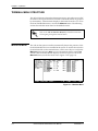
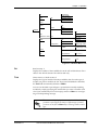
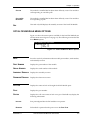
Octal and Quad FXS Modules
User Manual
Part Number 1200309L1 (Octal)
Part Number 1200328L1 (Quad)
61200309L1-1C
April 2000
901 Explorer Boulevard
P.O. Box 140000
Huntsville, AL 35814-4000
(256) 963-8000
© 2000 ADTRAN, Inc.
All Rights Reserved.
Printed in U.S.A.
Federal Communications Commission (FCC) Radio Frequency Interference Statement
This equipment has been tested and found to comply with the limits for a Class A digital device, pursuant to Part 15 of the FCC Rules. These limits are designed to provide reasonable protection against
harmful interference when the equipment is operated in a commercial environment. This equipment
generates, uses, and can radiate radio frequency energy and, if not installed and used in accordance
with the instruction manual, may cause harmful interference to radio frequencies. Operation of this
equipment in a residential area is likely to cause harmful interference in which case the user will be
required to correct the interference at his own expense.
Shielded cables must be used with this unit to ensure compliance with Class A FCC limits.
Change or modifications to this unit not expressly approved by the party responsible for compliance
could void the user’s authority to operate the equipment.
Canadian Emissions Requirements
This digital apparatus does not exceed the Class A limits for radio noise emissions from digital apparatus as set out in the interference-causing equipment standard entitled “Digital Apparatus,” ICES-003
of the Department of Communications.
Cet appareil numerique respecte les limites de bruits radioelectriques applicables aux appareils numeriques de Class A prescrites dans la norme sur le materiel brouilleur: “Appareils Numeriques,”
NMB-003 edictee par le Ministre des Communications.
iii
Limited Product Warranty
ADTRAN warrants that for five (5) years from the date of shipment to Customer, all products manufactured by ADTRAN will be free from defects in materials and workmanship. ADTRAN also warrants
that products will conform to the applicable specifications and drawings for such products, as contained in the Product Manual or in ADTRAN's internal specifications and drawings for such products
(which may or may not be reflected in the Product Manual). This warranty only applies if Customer
gives ADTRAN written notice of defects during the warranty period. Upon such notice, ADTRAN will,
at its option, either repair or replace the defective item. If ADTRAN is unable, in a reasonable time, to
repair or replace any equipment to a condition as warranted, Customer is entitled to a full refund of the
purchase price upon return of the equipment to ADTRAN. This warranty applies only to the original
purchaser and is not transferable without ADTRAN's express written permission. This warranty becomes null and void if Customer modifies or alters the equipment in any way, other than as specifically
authorized by ADTRAN.
EXCEPT FOR THE LIMITED WARRANTY DESCRIBED ABOVE, THE FOREGOING CONSTITUTES
THE SOLE AND EXCLUSIVE REMEDY OF THE CUSTOMER AND THE EXCLUSIVE LIABILITY OF
ADTRAN AND IS IN LIEU OF ANY AND ALL OTHER WARRANTIES (EXPRESSED OR IMPLIED).
ADTRAN SPECIFICALLY DISCLAIMS ALL OTHER WARRANTIES, INCLUDING (WITHOUT LIMITATION), ALL WARRANTIES OF MERCHANTABILITY AND FITNESS FOR A PARTICULAR PURPOSE. SOME STATES DO NOT ALLOW THE EXCLUSION OF IMPLIED WARRANTIES, SO THIS
EXCLUSION MAY NOT APPLY TO CUSTOMER.
In no event will ADTRAN or its suppliers be liable to Customer for any incidental, special, punitive,
exemplary or consequential damages experienced by either Customer or a third party (including, but
not limited to, loss of data or information, loss of profits, or loss of use). ADTRAN is not liable for damages for any cause whatsoever (whether based in contract, tort, or otherwise) in excess of the amount
paid for the item. Some states do not allow the limitation or exclusion of liability for incidental or consequential damages, so the above limitation or exclusion may not apply to Customer.
Warranty and Customer Service
ADTRAN will replace or repair this product within five years from the date of shipment if the product
does not meet its published specification, or if it fails while in service. For detailed warranty, repair, and
return information, refer to the ADTRAN Equipment Warranty and Repair and Return Policy Procedure (see the last page of this manual).
A return material authorization (RMA) is required prior to returning equipment to ADTRAN.
For service, RMA requests, or more information, see the last page of this manual for the toll-free contact
number.
iv
Table of Contents
List of Figures ....................................................................................................................................................vii
List of Tables....................................................................................................................................................... ix
Chapter 1
Introduction .............................................................................................................................. 1-1
Octal and Quad FXS Modules Overview ...................................................................................................... 1-1
Functional Description.............................................................................................................................. 1-1
Features ....................................................................................................................................................... 1-1
Physical Description .................................................................................................................................. 1-2
Chapter 2
Installation ................................................................................................................................ 2-1
Before Installing the Octal and Quad FXS Modules .................................................................................... 2-1
Shipping Contents ..................................................................................................................................... 2-1
Installing the Octal and Quad FXS Modules ................................................................................................ 2-1
Wiring ................................................................................................................................................................. 2-2
Power Up and Initialization ............................................................................................................................ 2-2
Operation Alarms ...................................................................................................................................... 2-2
Chapter 3
Operation .................................................................................................................................. 3-1
Overview ............................................................................................................................................................ 3-1
Terminal Menu Structure................................................................................................................................. 3-2
Modules Menu .................................................................................................................................................. 3-2
Slt ................................................................................................................................................................. 3-3
Type ............................................................................................................................................................ 3-3
Menu ........................................................................................................................................................... 3-4
Alarm .......................................................................................................................................................... 3-4
Test .............................................................................................................................................................. 3-4
State ............................................................................................................................................................. 3-4
Status .......................................................................................................................................................... 3-4
Online .................................................................................................................................................. 3-4
No Response ....................................................................................................................................... 3-4
Empty .................................................................................................................................................. 3-4
Offline .................................................................................................................................................. 3-5
Offline/No Response ........................................................................................................................ 3-5
Rev .............................................................................................................................................................. 3-5
Octal FXS Module Menu Options................................................................................................................... 3-5
Info ...................................................................................................................................................................... 3-5
Part Number .............................................................................................................................................. 3-5
Serial Number ........................................................................................................................................... 3-5
Assembly Revision ................................................................................................................................... 3-5
Firmware Revision .................................................................................................................................... 3-5
Status................................................................................................................................................................... 3-5
61200309L1
Octal and Quad FXS Modules User Manual
v
Table of Contents
Port .............................................................................................................................................................. 3-5
Status ........................................................................................................................................................... 3-5
Inactive ................................................................................................................................................ 3-5
Disabled ............................................................................................................................................... 3-5
Idle ....................................................................................................................................................... 3-6
Tip Open ............................................................................................................................................. 3-6
OffHook ............................................................................................................................................... 3-6
Reverse Battery ................................................................................................................................... 3-6
Test ....................................................................................................................................................... 3-6
Test – Active ....................................................................................................................................... 3-6
Test – Offhook .................................................................................................................................... 3-6
Test – Rev. Bat .................................................................................................................................... 3-6
Test – Ringing ..................................................................................................................................... 3-6
Test – Tip Open .................................................................................................................................. 3-6
Test – Ring GND ................................................................................................................................ 3-6
Test – (-R)TRIP ................................................................................................................................... 3-6
Rx ABCD .................................................................................................................................................... 3-6
Tx ABCD .................................................................................................................................................... 3-7
Test ...................................................................................................................................................................... 3-7
Test 2W ....................................................................................................................................................... 3-7
Tx ABCD .................................................................................................................................................... 3-7
1-KHz Tone ................................................................................................................................................ 3-8
Loopback .................................................................................................................................................... 3-8
Configuration..................................................................................................................................................... 3-8
Port .............................................................................................................................................................. 3-8
Port Name .................................................................................................................................................. 3-8
Rx Gain ....................................................................................................................................................... 3-8
Tx Gain ....................................................................................................................................................... 3-8
2W Impedance ........................................................................................................................................... 3-8
Coding Scheme .......................................................................................................................................... 3-8
ATLAS 550 Features Used with Octal FXS Module Options...................................................................... 3-9
Factory Restore .......................................................................................................................................... 3-9
Run Selftest ................................................................................................................................................ 3-9
Appendix A Dial Plan Interface Configuration ...................................................................................... A-1
Index ...........................................................................................................................................................Index-1
vi
Octal and Quad FXS Modules User Manual
61200309L1
List of Figures
Figure 1-1.
Figure 2-1.
Figure 3-1.
Figure 3-2.
Figure 3-3.
Figure A-1.
61200309L1
Octal FXS Module........................................................................................................................ 1-2
Installing the Octal and Quad FXS Modules ........................................................................... 2-1
Modules Menu............................................................................................................................. 3-2
Modules Menu Tree .................................................................................................................... 3-3
Octal FXS Module Menus Options ........................................................................................... 3-5
Dial Plan Menus ......................................................................................................................... A-1
Octal and Quad FXS Modules User Manual
vii
List of Figures
viii
Octal and Quad FXS Modules User Manual
61200309L1
List of Tables
Table 2-1.
Table 3-1.
61200309L1
Pinout Connection....................................................................................................................... 2-2
Test 2W ......................................................................................................................................... 3-7
Octal and Quad FXS Modules User Manual
ix
List of Tables
x
Octal and Quad FXS Modules User Manual
61200309L1
Chapter 1
Introduction
OCTAL AND QUAD FXS MODULES OVERVIEW
The Octal and Quad FXS Modules are members of the ATLAS 550 family of
products. Use the Octal and Quad FXS Modules in applications that require
analog phone interfaces. Potential applications include analog PBX trunk
circuits, modem banks, extension telephones, etc.
The Octal and Quad FXS Modules feature eight and four ports, respectively,
and provide talk battery, off-hook supervision, and ringing. The modules
combine with the ATLAS 550 Base Unit for FXS analog voice applications.
The Octal and Quad FXS Modules support loop-start and ground-start
operation. Call progress tones, where necessary, are provided to the
modules by the ATLAS 550 Base Unit.
Functional Description
The Octal and Quad FXS Modules install in any available option slot in the
ATLAS 550 chassis. Status information is available via the terminal menus,
accessible through either a VT-100 terminal connected to the ATLAS 550
control port or via a Telnet session established through the Base Unit’s
Ethernet port. Use the terminal menu to configure the Octal and Quad FXS
Modules and to download application software.
Features
The Octal and Quad FXS Modules have the following features:
61200309L1-1
•
Eight/four voice ports
•
Loop start and ground start
•
µ-law
•
Up to 100 ohms copper loop
(equivalent distance of 1900 feet of 24 AWG wire)
•
Hot-swappable
•
Flash download firmware
•
Rings into 5 REN per card
Octal and Quad FXS Modules User Manual
1-1
Chapter 1. Introduction
Physical Description
The Octal and Quad FXS Modules plug into any available option slot in the
rear of the ATLAS 550 chassis. Figure 1-1 shows the Octal FXS Module.
1
2
3
4
5
6
7
8
500 Series
OCTAL FXS
Figure 1-1. Octal FXS Module
The label over each modular connector refers to the corresponding port on
the module.
1-2
Octal and Quad FXS Modules User Manual
61200309L1-1
Chapter 2
Installation
BEFORE INSTALLING THE OCTAL AND QUAD FXS MODULES
Carefully unpack and inspect the Octal and Quad FXS Modules for shipping
damages. If you suspect damage occurred during shipping, file a claim immediately with the carrier and then contact ADTRAN Technical Support
(see the last page of this manual for pertinent information). If possible, keep
the original shipping container for returning the modules for repair or for
verification of shipping damage.
All references to the Octal FXS Module in this section are
applicable to the Quad FXS Module, with the difference that the
Quad FXS Module has four ports instead of eight.
Shipping Contents
The ADTRAN shipment includes the following items:
•
Octal FXS Module or Quad FXS Module
•
Octal and Quad FXS Modules User Manual
(Insert into the ATLAS 550 User Manual.)
INSTALLING THE OCTAL AND QUAD FXS MODULES
Figure 2-1 represents the actions required to install the Octal and Quad FXS
Modules properly, as described in the Step/Action table on page 2-2.
Remove Cover Plate
O
O I
I
4
2
ALL EMPTY SLOTS MUST BE
COVERED WITH BLANK PANELS
1
2
3
4
5
6
7
8
Series 500
NETWORK 2
FUSE RATING: 2A/250V SLO-BLO
ETHERNET
CONTROL
RELAY
CAUTION: FOR CONTINUED PROTECTION
AGAINST RISK OF FIRE, REPLACE ONLY
WITH SAME TYPE AND RATING OF FUSE.
90-240VAC, 2A, 50/60Hz
ALARM
OCTAL FXS
IN
OUT
MON
NC NO COM GND
Figure 2-1. Installing the Octal and Quad FXS Modules
61200309L1-1
Octal and Quad FXS Modules User Manual
2-1
Chapter 2. Installation
Instructions for Installing the Octal and Quad FXS Modules
Step
Action
1
Remove the cover plate from the appropriate option slot in the
ATLAS 550 rear panel.
2
Slide the module into the option slot until the it is firmly
positioned against the front of the chassis.
3
Secure the thumbscrews at both edges of the module. Tighten
with a screwdriver.
4
Connect the cables to the associated device(s).
5
Complete the installation of any remaining modules and Base
Unit as specified in the Installation chapter of the ATLAS 550
User Manual.
Option modules are intended to be serviced by qualified service
personnel only.
WIRING
Each module port has a single 8-pin modular jack. Connector pinout is compatible with (USOC) RJ-11C and is shown in Tabl e2-1.
Table 2-1. Pinout Connection
PIN
NAME
DESCRIPTION
1, 2, 3, 6, 7, 8
Unused —
4
Ring
Ring to and from the analog phone interface
5
Tip
Tip to and from the analog phone interface
POWER UP AND INITIALIZATION
The Octal and Quad FXS Modules require no initialization input during the
power-up sequence, as described in the ATLAS 550 User Manual. Any previously configured setting for the Octal and Quad FXS Modules is automatically restored upon power-up.
Operation Alarms
The red ALARM LED (located with the Module LEDs on the front panel) illuminates when an alarm condition is detected.
2-2
Octal and Quad FXS Modules User Manual
61200309L1-1
Chapter 3
Operation
OVERVIEW
All references to the Octal FXS Module in this section are
applicable to the Quad FXS Module, with the differences that the
Quad FXS Module has four ports instead of eight and is displayed
as FXS-4 in the menus.
The Octal FXS Module is controlled by the ATLAS 550 Base Unit terminal
menu. The terminal menu allows for detailed configuration, status, and testing of the Octal FXS Module.
Configuration of the Octal FXS Module is completed in two areas of the terminal menu:
1.
General configuration items (see the menu tree on page 3-2) for the
Octal FXS Voice Module are set using MODULES/FXS-8 MENUS/CONFIG.
2.
Specific configuration items depend on how the option module is used
and are displayed in the DIAL PLAN menus (see Appendix A).
Access the terminal menu using either a VT-100 terminal attached to the
ATLAS 550 Base Unit’s control port or a Telnet session established through
the Base Unit’s Ethernet port. The ATLAS 550 User Manual provides detailed
instructions on each of these management approaches.
To edit items in the terminal menu, you must have the appropriate
password level. Each menu description in this section indicates
the password level required for write and read access. See “Access
Passwords” in the ATLAS 550 User Manual for detailed
information on working with passwords. Security level 0 users
can view and edit every available field. Security level 5 users can
view any field but cannot edit.
61200309L1-1
Octal and Quad FXS Modules User Manual
3-1
Chapter 3. Operation
TERMINAL MENU STRUCTURE
The ATLAS 550 uses a hierarchical menu structure to provide access to all of
its features. The top-most menu level leads to submenus which are grouped
by functionality. All menu items display in the terminal window. To access
the Octal FXS Module menus, activate the MODULES menu. The following
sections describe the menu items for the Modules menu.
Refer to the ATLAS 550 User Manual for detailed instructions
on navigating through the terminal menu.
MODULES MENU
The ATLAS 550 system controller automatically detects the presence of the
Octal FXS Module when it is installed in the system. To see the menus for the
Octal FXS Module via the terminal menu, use the arrow keys to scroll to the
MODULES menu and press Enter to access the module choices in the TYPE
column. (The Octal FXS Module displays as FXS-8.) Figure 3-1 shows the
MODULES menu (see also the menu tree in Figure 3-2 on page 3-3).
Figure 3-1. Modules Menu
3-2
Octal and Quad FXS Modules User Manual
61200309L1-1
Chapter 3. Operation
Slt
Part Number
Serial Number
Type
Info
Assembly Revision
Firmware Revision
Menu
Alarm
Port
Status
Modules
Status
Rx ABCD
Tx ABCD
Port
Test
Test 2W
(Shortcut to Test) Test
Tx ABCD
1kHz Tone
State
Port
Loopback
Port Name
Configuration
Rx Gain
0 dB through -6 dB
Tx Gain
+3 dB through -6 dB
2W Impedance
600 + 2.16 µ
Coding Scheme
µ-Law
Status
Rev
Figure 3-2. Modules Menu Tree
SLT
Read security: 5
Displays the number of the available slots in the ATLAS 550 chassis. Slot 0
refers to the ATLAS 550 unit. This field is read-only.
TYPE
Write security: 3; Read security: 5
Displays the type of module currently installed in the slot or the type of
module you plan to install in the slot. If an Octal FXS Module is installed,
the TYPE field automatically defaults to FXS-8.
You can use this field to preconfigure a system before actually installing
modules by simply specifying the module that you want to install in each
slot. If you intentionally leave a slot empty, mark it as EMPTY to avoid getting a Not Responding message.
TYPE automatically displays the name of an installed module. If
you want to preconfigure the slot for a different type of module,
you must set this field to EMPTY before selecting another module
type.
61200309L1-1
Octal and Quad FXS Modules User Manual
3-3
Chapter 3. Operation
MENU
Displays additional status and configuration menus for the selected module.
To access the submenus for this item, use the arrow keys to scroll to the
MENU column for the module you want to edit, and press Enter. For detailed
information on each submenu item, see the section Octal FXS Module Menu
Options on page 3-5.
ALARM
Read security: 5
Displays an alarm condition on the Octal FXS Module. Press Enter in this
field to activate the menu.
TEST
Read security: 5
Displays the test name if the Octal FXS Module is executing a test. Press
Enter in this field to activate the menu. Tests include TEST 2W, TX ABCD,
1KHZ TONE, and LOOPBACK. See Test on page 3-7 for a description of each
test and its options.
STATE
Displays module status as either ONLINE or OFFLINE. Even though a module
is physically installed, it must be marked ONLINE for it to be considered an
available resource. This parameter allows an installed module to be marked
OFFLINE, which may be useful in system troubleshooting. If you choose
OFFLINE, the module will not be in alarm condition, but will display OFFLINE.
Once a module is installed, STATE must be set to ONLINE for the
ATLAS 550 to use the module for any data bandwidth.
STATUS
ONLINE
This read-only field provides status information on the Octal FXS Module. The
following messages may display:
The module is enabled and is responding to the system controller’s status
polls. This is the normal response of the system.
The ATLAS 550 ONLINE LED illuminates green when a call is
active on any of the voice ports.
3-4
NO RESPONSE
The module is enabled but is not responding to the system controller’s status
polls. This response indicates either a problem in the system or that the module is not installed.
EMPTY
The system controller has not detected the presence of a module in the slot;
nor has a module been manually enabled for this option slot.
Octal and Quad FXS Modules User Manual
61200309L1-1
Chapter 3. Operation
OFFLINE
The module is installed but has been taken offline by a user. The module is
still responding to controller polls.
OFFLINE/NO
RESPONSE
The module is installed but has been taken offline by a user. The module is
not responding to polls.
REV
This read-only field displays the assembly revision of the Octal FXS Module.
OCTAL FXS MODULE MENU OPTIONS
Figure 3-3 shows the menu options available for the Octal FXS Module (see
also the menu tree in Figure 3-2 on page 3-3). The following sections describe
these MENUS options.
Figure 3-3. Octal FXS Module Menus Options
INFO
Provides read-only information about module part number, serial number,
and assembly revision.
PART NUMBER
Displays the part number of the module.
SERIAL NUMBER
Displays the serial number of the module.
ASSEMBLY REVISION Displays the assembly revision.
FIRMWARE REVISION Displays the firmware revision.
STATUS
Displays the status of each of the eight Octal FXS Module ports.
PORT
Displays the port number.
STATUS
Displays the call or test status of each voice port. This field may display the
following information:
INACTIVE
Port preconfigured but the FXS module is not present.
DISABLED
FXS module is present but the port is not in the DIAL PLAN.
61200309L1-1
Octal and Quad FXS Modules User Manual
3-5
Chapter 3. Operation
IDLE
Loop Start – indicates the signaling method is set to loop start and the port
is waiting for seizure or an incoming call (see also Loop Start on page A-2).
Ground Start – indicates the signaling method is set to ground start and the
tip conductor is grounded (see also Ground Start on page A-2).
TIP OPEN
Loop Start – indicates the signaling method is set to loop start and a forward
disconnect state (FXS port removes the battery). See also Loop Start on page
A-2.
Ground Start – indicates the signaling method is set to ground start and the
unit is in normal idle condition (see also Ground Start on page A-2).
OFFHOOK
The FXS port has detected an offhook condition (loop current flowing).
REVERSE BATTERY
The FXS port has reversed T/R polarity.
TEST
This generic FXS port test indicator is used when multiple tests are being run
or if the test is not a 2W test.
TEST – ACTIVE
The FXS port is in test mode. Active test is selected.
TEST – OFFHOOK
The FXS port is in test mode. Active / Reverse Battery test is selected, but
Offhook condition is detected.
TEST – REV. BAT
The FXS port is in test mode. Reverse Battery test is selected.
TEST – RINGING
The FXS port is in test mode. Ringing test is selected.
TEST – TIP OPEN
The FXS port is in test mode. Tip Open test is selected.
TEST – RING GND
The FXS port is in test mode. Tip Open test is selected, but ring ground is detected.
TEST – (-R)TRIP
The FXS port is in test mode. Ringing test is selected, but an offhook condition is detected.
RX ABCD
3-6
Displays the receive signaling bits for FXS operation. If the port is in the DIAL
PLAN, this signaling represents Loop Start/Ground Start signaling (also see
Signaling Method on page A-2).
Octal and Quad FXS Modules User Manual
61200309L1-1
Chapter 3. Operation
TX ABCD
Displays the transmit signaling bits for FXS operation. This signaling represents Loop Start/Ground Start signaling if the port is in the DIAL PLAN (also
see Signaling Method on page A-2).
Receive and transmit signaling bits represent an LS/GS interface between
the ATLAS 550 controller and the voice port. The bit pattern is formatted
ESF RBS. Signaling bits have local significance only. For example, if the voice
port is mapped to a DS0 that has been set up for E&M signaling, the voice
port will still show LS/GS signaling.
TEST
Displays the test name if the Octal FXS Module is executing a test. Press
Enter in this field to activate the menu.
TEST 2W
Activates 2W (FXS) tests on a per-port basis. Options include OFF, ACTIVE,
TIP OPEN, REV. BATTERY, DISABLED, and RINGING. Table 3-1 displays the state
of the 2W conductors during each test.
2W tests disrupt calls in progress.
Table 3-1. Test 2W
Test
Tip Output
Ring Output
Off
No test active
No test active
Active
Ground
Supervision voltage
Tip Open
High impedance
Supervision voltage
Rev. Battery
Supervision voltage
Ground
Disableda
High impedance
High impedance
Ringing
Ringing voltage
Ringing voltage
a. Disables the output of the FXS port; it does not disable the test.
TX ABCD
Forces the transmit (Tx) Robbed Bit Signaling (RBS) to a specified value. Values include OFF, 0000, 0101, 1010, and 1111.
Calls may be affected when activating the Tx ABCD test. This test
is not valid when the port is used in the DIAL PLAN.
61200309L1-1
Octal and Quad FXS Modules User Manual
3-7
Chapter 3. Operation
1-KHZ TONE
Sends a 1 KHz tone into the following locations, based on test selection:
NEAR sends the tone out the 2W FXS port, while FAR sends the tone into the
digital PCM stream of the ATLAS 550 controller. The tests are useful for verifying a voice path.
LOOPBACK
Activates loopback tests on a per-port basis.
Normal operation
OFF
ANALOG Loops the 2W on itself.
DIGITAL
Loops digital data entering the FXS-port from the ATLAS
controller on itself.
BOTH
Processes both Analog and Digital Loopback tests.
Loopback tests disrupt calls in progress.
CONFIGURATION
Provides menu options for configuring the module.
PORT
Identifies the port.
PORT NAME
Allows the user to assign a meaningful name to the port.
RX GAIN
Adjusts the (+)Gain and (-)Attenuation of a digital signal transmitted out an
FXS port (Digital-to-Analog.) The range includes 0, -3, and -6 dB.
TX GAIN
Adjusts the (+)Gain and (-)Attenuation of a digital signal transmitted into an
FXS. The range includes +3, 0, -3, and -6 dB.
When the digital signal is connected through the PSTN, a setting
of 0 dB should be used.
2W IMPEDANCE
2 Wire input impedance is set to 600 ohms +2.16 uF. This is a read-only field.
CODING SCHEME
The PCM coding scheme is set to µ-Law. This is a read-only field.
3-8
Octal and Quad FXS Modules User Manual
61200309L1-1
Chapter 3. Operation
ATLAS 550 FEATURES USED WITH OCTAL FXS MODULE OPTIONS
Two additional ATLAS 550 menu items can operate in conjunction with the
Octal FXS Module: FACTORY RESTORE and RUN SELFTEST.
FACTORY RESTORE
You can restore the factory default settings for an Octal FXS Module by
pressing F either while the cursor is over the SLT number (this action restores
the factory settings for all of the module options) or while the cursor is over
an individual field (this action restores factory settings for the particular
field only).
RUN SELFTEST
RUN SELFTEST, a submenu of the ATLAS 550 main menu item TEST, executes
both the Octal FXS Module internal test and the ATLAS 550 internal test.
When RUN SELFTEST displays, place the cursor on it and press Enter to execute the test. The unit continuously changes the display on the self-test log
screen until all test results are shown. For additional information on RUN
SELFTEST, see the ATLAS 550 User Manual.
61200309L1-1
Octal and Quad FXS Modules User Manual
3-9
Chapter 3. Operation
3-10
Octal and Quad FXS Modules User Manual
61200309L1-1
Appendix A
Dial Plan Interface Configuration
All references to the Octal FXS Module in this chapter are
applicable to the Quad FXS Module, with the differences being
that the Quad Module has four ports instead of eight and is
displayed as FXS-4 in the menus.
INTERFACE CONFIGURATION
The IFCE CONFIG option for the DIAL PLAN menu (see Figure A-1) sets configuration parameters for the endpoint. These parameters vary by the type of
port selected. The DIAL PLAN menus are only accessible when using terminal
mode. To access these options, select DIAL PLAN from the top level menu.
Figure A-1. Dial Plan Menus
OCTAL FXS MODULE INTERFACE CONFIGURATION
The following sections describe USER TERM configuration settings for the
Octal FXS Module when using the DIAL PLAN menus.
USER TERM
61200309L1-1
When interfacing to user equipment (terminal adapters), the Octal FXS
Module acts like the network. In this case, configure the DIAL PLAN as
follows: Select USER TERM and define SLT as FXS-8. The following IFCE
CONFIG options are then available.
Octal and Quad FXS Modules User Manual
A-1
Appendix A. Dial Plan Interface Configuration
PORTS AVAILABLE
Read security: 5
Shows port allocation for the endpoint. The characters used to define the
allocation have the following meanings:
0-9
Describes available ports, as indicated by the displayed digit. This
digit is the last digit of the port number.
!
The endpoint uses this port.
s
The switched dial plan uses this port elsewhere.
S
The switched dial plan uses this port elsewhere and a conflict exists with this endpoint.
n
One or more dedicated (nailed) maps use this port.
N
One or more dedicated (nailed) maps use this port and a conflict
exists with this endpoint.
-
Indicates that this is the wrong kind of port for this endpoint.
NUMBER OF
PORTS
Write security: 2; Read security: 5
Defines the number of ports that could be used to answer calls to the numbers defined in the Accept Call list. The ports are contiguous beginning with
the port number selected and the number of ports.
SIGNALING
METHOD
Defines to the ATLAS 550 the type of signaling to be used on this analog interface. The signaling selected needs to match the 2W supervision of the connected trunk. Options include LOOP START and GROUND START.
LOOP START
Defines to the ATLAS 550 the most common 2W supervision.
GROUND START
Defines to the ATLAS 550 the 2W supervision used by some PBXs.
FORWARD
DISCONNECT
Sets the time for a loop current to stop flowing once the other end terminates
the call. This feature is useful for applications such as Fax Servers and
ACDs. This option is only applicable for LOOP START applications. Options
include DISABLED, 600 MS, 1000 MS, and 2000 MS.
DIRECT INWARD
DIALING
Write security: 3; Read security: 5
Defines whether the end-user equipment requires digits to be delivered
after going off-hook.
CALLER ID
Assigns a calling party number to a port when it originates a call and the call
exits a PRI interface.
NUMBER
DID DIGITS
TRANSFERRED
A-2
Defines the number of digits sent to the end-user equipment. This field displays only if DIRECT INWARD DIALING is set to ENABLED.
Octal and Quad FXS Modules User Manual
61200309L1-1
Appendix A. Dial Plan Interface Configuration
STRIP MSD
Write security: 3; Read security: 5
Strips a selected quantity (choose from NONE, 1, 2, and 3) of the Most Significant Digits (MSD) of a dialed number prior to being forwarded out of the
port.
EXAMPLE:
A network port could be set to accept all calls beginning with 9 (9$), and
then with STRIP MSD set to 1, all digits would be sent toward the network
except the leading 9.
STRIP MSD does not affect CALL ACCEPT criteria. All of the digits
(including the MSDs that are subsequently stripped) are used as
accept criteria.
SOURCE ID
Write security: 3; Read security: 5
Simplifies the creation of a DIAL PLAN in applications where the criterion for
switching calls to a certain endpoint is a function of which endpoint originated the call.
•
Default value = 0. The default ID for all endpoints is 0 and all accept
numbers is 0. With default values, all calls are routed based only on the
dialed number.
•
Multiple endpoints can have the same SOURCE ID.
•
When creating the CALL ACCEPT list, specify a SOURCE ID(s) as well as a
dialed number or range of dialed numbers to accept.
EXAMPLE:
An application requires that all calls that originate from Port 1 of the Octal
FXS Module in Slot 1 be switched to Port 2 of that same module. Assign a
unique Source ID (e.g., 7) to Port 1 of the module, and then configure Port 2
to accept calls only from that unique Source ID (7).
DIAL ON
OFFHOOK
Write security: 3; Read security: 5
Defines a number that is automatically sent to the switchboard when a call
on this port goes offhook.
The Dial on Offhook number must be specific (i.e., no "wild cards").
61200309L1-1
Octal and Quad FXS Modules User Manual
A-3
Appendix A. Dial Plan Interface Configuration
A-4
Octal and Quad FXS Modules User Manual
61200309L1-1
Index
Numerics
L
1-kHz Tone 3-8
2W Impedance 3-8
limited product warranty iv
Loop Start A-2
Loop Start (Idle) 3-6
Loop Start (Tip Open) 3-6
Loopback 3-8
A
Alarm 3-4
alarms 2-2
C
Caller ID A-2
Coding Scheme 3-8
Configuration 3-8
customer service iv
D
description 1-1
physical 1-2
Dial on Offhook A-3
Dial Plan A-1
DID Digits Transferred A-2
Direct Inward Dialing A-2
M
Menu 3-4
menu structure 3-2
menus and submenus
Ifce Configuration A-1
Modules Menu 3-2
N
network pinout 2-2
Number of Ports A-2
O
operation 3-1
operation alarms 2-2
F
P
factory default settings 3-9
Factory Restore 3-9
features 1-1
Forward Disconnect A-2
passwords 3-1
pinout 2-2
Port (Configuration) 3-8
Port (Status) 3-5
Port Name 3-8
Ports Available A-2
power up 2-2
G
Ground Start A-2
Ground Start (Idle) 3-6
Ground Start (Tip Open) 3-6
I
initialization 2-2
installing the module 2-1
Interface Configuration A-1
introduction 1-1
61200309L1
R
Rev 3-5
ring output 3-7
RMA requests iv
Run Selftest 3-9
Rx ABCD 3-6
Rx Gain 3-8
Octal and Quad FXS Modules User Manual
Index-1
Index
S
security levels 3-1
self-test 3-9
service iv
shipping contents 2-1
Signaling Method A-2
Slt 3-3
Source ID A-3
specifications 1-2
State 3-4
Status 3-4
Empty 3-4
No Response 3-4
Offline 3-5
Offline/No Response 3-5
Online 3-4
Status (Module) 3-5
Status (Status) 3-5
Disabled 3-5
Idle 3-6
Inactive 3-5
OffHook 3-6
Reverse Battery 3-6
Test 3-6
Test – (-R)TRIP 3-6
Index-2
Test – Active 3-6
Test – Offhook 3-6
Test – Rev. Bat 3-6
Test – Ring GND 3-6
Test – Ringing 3-6
Test – Tip Open 3-6
Tip Open 3-6
Strip MSD A-3
T
terminal menu structure 3-2
Test 3-4, 3-7
Test 2W 3-7
tip output 3-7
Tx ABCD 3-7
Tx Gain 3-8
Type 3-3
U
User Term A-1
W
warranty iv
wiring 2-2
Octal and Quad FXS Modules User Manual
61200309L1
Product Support Information
Pre-Sales Inquiries and Applications Support
Please contact your local distributor, ADTRAN Applications Engineering, or ADTRAN Sales:
Applications Engineering
(800) 615-1176
Sales
(800) 827-0807
Post-Sale Support
Please contact your local distributor first. If your local distributor cannot help, please contact ADTRAN
Technical Support and have the unit serial number available.
Technical Support
(888) 4ADTRAN
Repair and Return
If ADTRAN Technical Support determines that a repair is needed, Technical Support will coordinate with
the Customer and Product Service (CAPS) department to issue an RMA number. For information regarding equipment currently in house or possible fees associated with repair, contact CAPS directly at the following number:
CAPS Department
(256) 963-8722
Identify the RMA number clearly on the package (below address), and return to the following address:
ADTRAN Customer and Product Service
6767 Old Madison Pike
Building #6 Suite 690
Huntsville, Alabama 35807
RMA # _____________