1
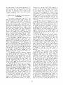
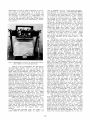
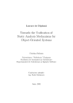
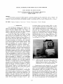
DIGITAL STEREOPLOTTING USING THE PC-SVGA MONITOR
J6zef Jachimski and Janusz Zielinski
Facul ty of Mining Geodesy and Environmental Engineering
University of Mining & Metallurgy (AGH)
Cracow, Poland
ABSTRACT:
For the general purpose PC-SVGA computer a program package has been elaborated which enables the
visualization and stereoscopic measurement of pairs of digital images. In the paper the most vital information concerning software and hardware design is discussed and the plotter characteristic is given.
KEY WORDS: Computer Graphics, Analytical, Plotter, Stereoscopic, Digital Systems
1. INTRODUCTION
land Information Systems (LIS) comprise variety of descriptive information, but on the
first place they comprise geometrical data in a
form of vectorial thematic maps. The number of
thematic layers certifies not only the universality of a data base, but also the amount of money
needed to keep the data base up to date.
In the data base there is cadastral information, which is of legal type, and must be kept
actual with the high geometrical accuracy. But in
the data base can be several other t.hematic layers which comprise information about land use in
t.he form of vectorial maps. Such information, however, often could be read easily directly from
the aerial pictures. It would be less expensive
to keep such geometrical information in the "passive" form of digital rast.er images scanned from
aerial photographs, than to read in advance from
them the coordinates of various contours, etc.
for thematic geometrical vectorial information.
Geometrisation of cont.ent of aerial photographs taken from the relatively low altitude,
always must consider also the differentiation of
the land topographical surface. The stereoscopjc
images must be used to ensure proper perception
and proper survey of details. There are two types
of precisely measurable continuous tone images of
the land surface: stereogram and stereoorthophotogram. A stereogram is a purely natural preduct
of the photogrammetric flight and it would require only scanning t.o be stored in the digital data
base of LIS. Stereoorthophotogram it is a preprocessed st.ereogram. It. consists of orthophotogram
and its stereopartner [Blachut 1971, Jachimski
1978]. Both of t.hem they are preprocessed aerial
photographs, therefore must be more expensive
than natural stereopare, but t.hey offer great advantages. It is much easier to superimpose vectorial map on orthophotoplan than on a photograph,
because neither elevations of points of numerical
vectorial map nor orientation elements of photographs are needed. It is also easier to store and
select proper fragment of orthophotogram and its
stereopartner than to play with many framepictures in the perspective projection, which irregularly cover the land.
Ortho-stereopares are produced in t.he process of differential rectification. Differential
rectification can be carried out fully automatically using automatic correlation procedure, and
t.his procedure doesn't. require any additional information but just properly oriented natural stereomedel. Automatic correlation is not advantageous however for preduction ortho-stereopares in
large scales or medium scales for urbanized tel~
rains. For such cases it is safer to use a pre-
processed digital elevation medel (DIM) to cont.rol also automatically the differential rectification process. Differential rectification of natural analogue pictures may be performed with a
very high accuracy using a slit -differentialrectifier (eg.: Avioplan OR1-Wild, or Orthocomp
Z2 Zeiss). The pre-scanned halftone analogue pictures in the raster-digital form can be also djfferentially rectified using adequate software
package and even only PC- type computers. Here
also rectification can be accomplished using automatic correlation rules [eg.Agnard et al 1990J
or using preprocesed digital elevation medel
[eg.Jachimski et al.1988].
Fig.1. Comput.er PC/386 with the colour 14" graphical monitor. The mirror stereoscope in
special mount allows for the comfortable
operator position when plotting (here the
stereoscope is in the rest.ing position)
Considering the real feasibility to include
the digital halftone raster images to the LIS data base we started some programing experiments in
1982. First the program to preduce digital orthophoto was made [1985] than followed digital stereoorthophoto [1989] and programs to visualize
and edit the vectorial numerical map on the PC
monitor with the halftone digital raster image in
the background. First we developed programs for
EGA graphics, and than for SVGA 800x600. Finally
programs for stereoscopic survey of photopairs on
SVGA 800x600 was produced. It is our hope, that
soon for better resolution SVGA 1024x768 programs
will also be accomplished. All this programs are
127
densities for various image areas [Aguard et
al .1990]. Considering the 30 steps halftone scale
as sufficient for halftone image visualization,
we can theoretically use 8 various
coloL~s
halftone scales simultaneously on the screen
having additionally approach to 16 bright coloill~s
to show varioL~
thematic vectorial
maps
(8x30+16=256). In practice however. for the human
physiology reasons, the number of colours used
simultaneOL~ly for half tone image visualization,
or number of COlOllO L~ed for the vectorial map
visualization must be limited to make
the
observation easy and to reduce the human operator
confusion.
It should be mentioned here, that there are
Lmexpected difficulties in programming of graphics. The producers of the graphic cards openly
supply usually only 1 imited routines l~ing the
BIOS commands, which provide exclusively the functions for writing or reading the single pixel in
the graphic card memory. This doesn't. facilitate
the programming of t.he effective and fast graphic
procedures such iiS procedure of a block visual ization needed for the image animation or the procedure of memorization of t.he chosen fragment of
image on the screen, so to program before the
G. Sutty' s [1990] pub 1 iCdti on was avai lable we had
to disassembl y the BIOS procedures t.o grab the
necessary inform,"ltion.
The computer monitors of 19" or 17" size are
often in l~e, but most popular and most economical is monitor 14" (image size is smaller, approx. 240x180mm). The monitor screen in the most
cases is shaped like rectangle 4:3. From t.he
point of view of proper image perception by the
human operator it is quite important to form on
the computer screen an image geometrically similar t.o the original. Let us assume that a scanner
records t.he digital image using circular (or
square) pixels arranged in the regular square
grid. To reproduce such regulae digital image on
the screen without. affine deformation a certain
graphical mode should be employed, such, t.hat
proportion of the number of pixels in the line to
the number of lines on the screen should be
4:3=1.33, alike as proportion of the screen dimensions.
The best shape of the image
displayed
on the screen is at. the graphical mode 1024x768
(1024/768=1,33) and 800x600 (1,33). The
EGA
640x350 (1,9) mode gives great affine image deformation (43%). Even
the
high resolution
1280xl024 (1,25) used with the bigger monitors
gives some, but rather small affine scale deformation (6%), which in many cases could be cleared
by certain electronic adjust.ment of
monitor
though. From the point of view of image geometry
the modes 1024x768 and 800x600 are excellent. On
t.he 14" monitors in the first. case digital image
is displayed using pixel ¢ = 0.23mm, in the second case pixel ¢ = O.30mm. Pixels of that size
assures easy perception of a halftone image on
the screen. The image granularity is noticeable,
but doesn't make difficult neither the bare eyed
observation nor the stereoscopic observation with
the use of minAor stereoscope.
For the stereoscopic observation the two
stereoscopic images are displayed at once on the
left and right halves of the screen. The stereoscope is placed horizontally in front of the monitor using special mount (fig.1 and 2), to allow
for comfortable operator position. From the nature of the digital image appears that to each pixel the image coordinates are assigned almost in
the moment of it.s registration (scanning). It is
enough to apply a t.ransformation to standard pixel coordinates to get the coordinates of each
pixel in the fiducial coordinate system. So, the
to be applied as an user oriented peripherals to
the LIS-. User should be able to examine his thematic vectorial map (eg. cadastral) on the PC monitor with the halftone terrain image in the
background, and to produce a new vectorial thematic map if necessary using an accurate stereosurvey on the screen.
2. CONDITIONS OF THE METRICAL USE OF GRAPHICS ON
PC-MONITORS
The initial configl~ation of the PC-AT computer for which the Digital Screen Plotter was
programmed included the ffiA graphics. B3A card
allows to generate only 4 steps of luminosity for
each of 3 RGB colours and for each of 640x350
points on the screen. To get a grey coloL~ of
point one must generate equal It.uninosity for 3
RGB colours. To broaden the 4 steps grey-scale to
show better the image details the 4 steps extension scale in the colour close to neutral grey
(black green) was designed. Such 8 steps halftone
scale was very contrast and gave urmaturally
coloured but readable halftone images; unfortLmately it was not possible to broaden the scale
further (for example to 12 steps). Remaining 8 of
the 16 colours of B3A palette capacity could be
used to visualize simultaneously variety of 8 different thematic layers of LIS vectorial numerical map; at that stage of development only 4
bright colours to show vectors (red, blue, green,
yellow) were used in our program.
The development of graphics hardware for PC
computers resul ted in VGA and SVGA cards. TI1e
available popular SVGA cards allow for the maximum resol ution of 1024..,,<768 pixels and palette of
256 colours available simultaneously on the
screen of analcgue monitor. The luminosity of
each of the basic RGB colours can vary3 within the
range of 64 steps scale, what gives 64 =256 K of
various colours available. The grey halftone scale can be produced within the maximum of 64 steps
scale. For each colour (including grey) available
simul taneously on the screen a palette code num-bel" of 0+255 is assigned, and one byte of memory
on the graphic card is used to remember the code
number for each pixel of the halftone image produced on the monitor screen.
The maximum resolution requires 1024x768
x1Byte=768Kb memory available on the graphic
card. There are relatively popular cards which
offer 1~1b memory and can easily handle the 256
colours palette for the top resolution, but many
of them offer only 512Kb memory, and therefore
can produce only palette of 16 colours for the
top resolution of 1024x768 (the code number for
one pixel requires only half of a byte). In the
case of 512Kb memory only lower resolution
800x600 pixels image can be produced with the use
of 256 colours palette.
Among the SVGA cards avai lable on the market
quite interesting are cards employing graphic
processor IT 3000 (or IT 4000) produced by TSENG
LABORATORIES. The card producer supplies a card
contro1ler program which enables the use of such
functions of graphic processor as image magnification (ZOOM) or image shifting (SCROLL) in the
chosen window on the screen. Admittedly the card
contro1ler is open to fulfill such functions only
in the standard lower graphics modes, but we
found experimentally that they are available also
in the high resolution modes (with some limitation however at the 800x600 pixel resolution).
The broad 256 colours palette creates a
chance to distinguish on the screen several
thematic areas by the L~e not only the greyscale, but also the coloured scales of relative
128
used to remember one full screen when the resolution 800x600 is employed (800x600xlByte=469Kb).
Similarly on the card with the memory lKb used at
the 1024x768 resolution mode only 768Kb of memory
is occupied by the image needed for one screen.
So in the both cases a portion of memory reminds
for writing in the card memory an image greater
than needed for one screen visualization which
enables the natural vertical image scrolling on
the screen. An image projected onto the monitor
screen is selected from the memory in the card by
the address of the first pixel of that image (the
upper left corner of the screen) within onedimensional image table (image vector) existing
in the card memory. The natural image scrolling
on the screen is obtained by successive selection
of images shifted by the number of pixels which
compose one full image line on the screen (image
line length). Naturally certain line of a subsequently shifted image begins with the pixel number greater (smaller) by the number equal to the
line length.
The natural scrolling 1's limited to the number of additional picture lines (lines exceeding
the screen capacity) existing in the card memory.
Selection of the pixel address greater (smaller)
than that really existing in the card memory causes the address overflow which is reduced by subtraction from that unusual address the number
equal to the full capacity of the card memOJ:''Y. So
e.g. the address next to the greatest existing on
the card memory is the address of the first pixel
in the image vector. Therefore the scrolling
which exceeds the number of additional lines in
the card memory gives in the cyclic visualization
the repetition of that image portions which were
removed from the screen at the beginning of scrolling. The effect of undisturbed cyclic scrolling
in boundru}' conditions is possible only in case
when the full card memory capacity can be divided by the image 1ine length without remainder.
Otherwise the shifted image details within each
subsequent 1ine of overflown numbers appear on
the upper (lower) part of the screen. Luckily in
such case exclusively the position of pixels selected by the overflown numbers is incorrect what
causes practically the ruin of only the uppest or
lowest margin of the image on the screen, leaving
other parts of the image undisturbed. In the case
of the resolution 102Lb~768 with the 1Mb memory in
the card the undisturbed cycle of scrolling is
assured (the lines with the overf1 Owrl numbers
will create on the top margin of the screen the
repetition of the lowest part of the image existing in the card memmy, or vice versa). But
using the 800x600 resolution mode we are getting
only 55 lines of undisturbed vertical scrolling
(512xl024/800-600=55.36) , and
afterwards
the
shift of image details by 288 pixels along subsequent lines appears on the upper or lower margin
of the screen (0.36x800=288). Fortunately the remaining part of the screen remairs undisturbed.
what makes the plotting possible even in such not
very comfortable conditions. but using the popular (and not expensive) g:t-aphical mode hardware.
The analysis of the value of y-parallax can
show the cases when such less favorable conditions appear. Let us assume that an aerial stereopru-e was scanned using ¢=25,um pixels. This
means, that on one monitor screen simultaneously
can be displayed portion of the left and right
picture of the size 400x600 pixels or 1024x768
pixels what after multiplication by pixel size
gives the aerial picture area lOx15mm for 800x600
graphical mode or 12.8mmx19,2mm for the 1o24x768
graphical mode. Assuming that the usable photogram area does not exceed 220x220mm, we can calculate the y-parallaxes changeability at the cor-
measurement of digital image displayed on the monitor lies in the selection of the No of the pixel assigned to certain detail of interest. The
affinism of the image display on the screen does
not influence the accuracy of measurement, but
only disturbs the human operator imagination. It
is one of the features of plotting on the screen,
that there should not exist instrumental adjustment errors.
Fig.2. Stereoscope in front of the monitor,equipment ready for the stereoplotting
Similar rules of measurement are applied for
the stcx'Gopare survey. There are Lwo stereopictures displayed on the two halves of the
screen. On each of them the separate cursor of
equal shape is superimposed. Both cursors can be
moved simultaneously, and additionally the right
cursor can be shifted only in the x-direction to
measure the x-parallax. When measuring stereoorthophotogram such shifts of cursor are quite
sufficient. But to prepare for survey on stereoorthophotogram when the components of the stereopare are badly correlated, or in case of preparing for survey of natural stereogram (survey for
relative orientation), there is need for independent shift of the right cursor also in the ydirection. The stereoscopic measurement with the
large y-observation-parallax is not possible.
Therefore a certain software function have been
designed which allows to clear such parallax by
the renewed display of right and left images
around cursors in similar position on the right
and left portions of the screen. This function is
designed to clear big y-parallaxes only during
the preparatory stage of relative orientation.
After the natural-stereopare has been relatively oriented the operator should be getting
the y-parallax-free stereo-vision.To keep the
cursor y-parallax-free during the observation of
natural stereopare the vertical scrolling of at
least one of the pictures composing stereopare
must be used. And here certain problem of that
scrolling range for the popular SVGA
cards
appears.
On the card equipped with the memory of
512Kb (TSENG IT 3000) only 469Kb of memory are
129
torial contest, and blows-up all the image. As
the result the vectors are not only longer. but
also thicker, what is not very convenient. Therefore it is better to use specially pro<.;;rrammed
procedures for image magnification. The advantage
of the hardware ZOOM function it is its high
speed though.
The potential accuracy of the surveying on
the screen is limited by the pixel original size
(refen-ed to the original scanned picture, or to
the object). Proper selection of pixels during
the plotting procedure can not result in the accuracy greater than 50% of the pixel size. But
there is a great possibility to enhance the measurement accuracy by the computer-supported measurement. If the measured point it is not a dot
imaged by one pixel. but it is defined rather by
the crossection of lines or by a target of the
known shape - the mathematical analysis of chosen
digital image portion can be applied. There are
already
excellent
results
published
(eg.
[Streilein & Beyer,1991] or (Jachimski & Trocha,
1992]). which show that in the very favorable
conditions the point determination accuracy can
be 0.1 or even 0.05 of the pixel size. This are
very interesting prospects for the development of
the plotting techniques on the screen of a
monitor.
ner of the photogram. For the 1024x768 mode the
natural scrolling will not exceed 55 lines x 25~m
= 1.375mm. Assuming that this would be the maximum of allowable y-parallax which will not cause
the display irregularities, and assuming that values of elements of angular relative orientation
are equal to each other. one can calculate that
this angular elements should not exceed 1~8, what
is not very little. When greater y-parallaxes increment will appear on the screen the plotting
will still be possible, but with the above mentioned sensations, or with the intel~ediate rewriting of the card memory to conveniently display the adequate portions of both images). For
the 1024x768 mode the natural scrolling allows
for changes of y-pal-allaxes not greater than 256
lines x 25~m = 6.4mm within one screen image por-tion. This would be sufficient even for the very
badly oriented aerial pictures.
There are several possible shapes of cursors
which could be used to point out the chosen pixel
in the screen. We selected the most convenient:
the alTOW with blinking pixel in its fore-part,
the square thin frame with blinking pixel in the
middle (seems to be the best for measurements),
and the cross with the arm-lines broken in the
middle and blinking pixel pointing out the center. The colour of cursor can be assigned freely,
but the best colour of the bl inking whi te-dark
pixel is similar to the colour of the halftone
image exposed on the screen to be measured. The
pixel blinking is controlled by the computer interrupt, so the blinking period does not depend
on the programmed operation of editing the vectorial map.
The techniqJe of operation using the chosen
block of pixels is used to create and animate the
cursor on the screen. The shapes of cursors are
"remembered" in blocks (matrices) in the computer
memory . The cursor matrix is written to the
screen memory in the chosen cursor position,
while the image position masked by the cursor is
temporally kept in computer. To change the cursor
position, the stored image portion must be rewritten to the present cursor position while the cursor wi 11 replace the neighboring portion of image (which is again stored in the computer), etc.
One of the important features of the screenplotting it is simultaneous display of the vectorial map with the halftone image in the background.
In the vector-graphics the objects defined
as the line segments are visualized on the screen
as a sets of pixels. The coexistence of the vectors superimposed on the halftone image on the
screen is possible by the visualization of the
raster halftone full image which is then masked
by pixels which create a vector. The masked pixels must be erased for that from the screen memory, and they can be regenerated two ways:
- by afresh visualization of the full screen
containing vectors and halftone image,
- by recording in the computer memory the pixels
masked by line segments, to use them again if
necessary.
The first method have been used in our programs
when the existing line segment had to be erased,
while the second method was very convenient for
the line segment animation (design).
Zooming it is quite useful function of program when plotting on the screen. It can be used
to enhance the operator confidence when selecting
(pointing by cursor) pixels to measure the halftone image details, or to have a general look on
the scene. The provided by the manufacturer ZOOM
function (harware) is not always convenient.
That
hardware image magnification
technique
doesn't distinguish between the halftone and vec-
3. '!HE AGH DIGITAL SCREEN
SI'EREDP~
As it was mentioned at the beginning of this
paper, the program and hardware for the stereoplotting on the screen was developed by the
authors at The University laboratories. Our Digital Screen Stereoplotter was originally designed
as a stereocompiler [Blachut,1971] which can facilitate the use of the stereoorthophotographs by
the LIS customers. It comprises the following
functions:
- the stereoscopic selection of the fragment of
the ha 1 ftone image on the stereoorthophotogram
displayed on the screen at the reduced scale,
- selection of the thematic maps which are to be
displayed on the monitor from the numerical
map files.
- the stereoscopic survey and plotting of chosen
features from the stereoorthophotogram using
polygon or trajectory in the selected colour.
The colours are assigned to the max.6 thematic
layers,
- zooming the image displayed by the integer
factor. The image in the original scale and
enlargement can be replaced by each other on
the screen, and plotting can continue in both
scales,
not desired details of the vectorial map can
be erased from the screen, and then from the
numerical map file (database),
- the line segments can be animated on the
screen to facilitate designing,
- the inscriptions can be introduced.
All the functions connected directly with
point measurement or plotting of polygon or trajectory are mouse conb-olled. The mouse of PC/AT
has 3 programmable buttons, which can be used to
move cursor up or down in the space. to register
the point, or beginning (end) of the line.
In the preparatory mode the mouse can move
cursors separately on the left or right picture
of stereopare. When the left and right cursors
points out identical details a command can be
used to shift both cursors together with the images so, that both cursors are placed just in the
center of the left and right screen parts.
For the use of stereoorthophotographs which
are in the local coordinate system the functions
130
Address for mail:
were designed to use them with the data bank coordinate system. New coordinate system can be determined by transformation using two or more chosen points, or approximately by just one point,
azimuth of given line segment and given scale
factor (size of the pixel) .
The present program was developed for the
PC/AT, SVGA 800x600/256 card and 14" screen. Further development is planned
for
the
card
1024x768/256 and not only for the stereoorthophotography but for the natural stereopares also.
We hope for the liquid-crystal screen and
for the optical discs which should facilitate very much the system versatility and comfort for
the users. The combination of computer controlled
liquid crystal glasses and the liquid crystal
screen allows to get the stereo-effect without
mirror stereoscope what makes the operator work
much more comfortable. Considering the mass-use
of the system though we must keep in mind also
the possibilities of the popular and not expensive hardware.
Prof. Dr. J6zef Jachimski & Mgr. Eng. Janusz Zi e 1inski
Photogrammetric Research
The Faculty of Mining Geodesy and Environmental
Engineeri ng
University of Mining & Metallurgy (AGH)
Al.Mickiewicza 30-C4, 30059 Krak6w, Poland
Tel. (04812)338100 ext.3826 or 2272,
Fax (04812)331014
BIBLIOGRAPHY
Agnard J.P. ,Gagnon P.A.,Nolette C.,Bouilianne M.,
1990. itA computer based general photcgrammetric system". Photcgrammetric Engineering and
Remote Sensing 5/1990 p.623-625
Blachut T. J ., 1971. "Mapping and Photointerpretation System Based on
Stereo-orthophotos" .
Mitteilungen aus dem Institut fur Geodesie und
Photogrammetrie
auch
der
Eidgen6ssischen
Technischen Hochschule Zurich, 14/1971
Jachimski J., 1978. "Problem stereoskopii w ortofotografii" (The Stereoscopy Problem in Orthophotography) , Zeszyty Naukowe AGH
Krak6w,
Geodezja 54/1978,s.3-121
Jachimski J., Trocha W., 1992. "Dete1'1llination of
the position of crosses with the subpixel
accura cy on the image taken with the CCD
camera" . Internat. Arch. Photogrammetry & Remote
Sensing, Commission V, Washington 1992
Jachimski J., Mierzwa W., Pyka K. , Boron A.,
Zielinski J. ,1988. "Digital Image Rectification
on Microcomputers for Orthophoto Production".
Internat.Arch.Photogrammetry & Remote Sensing,
Vol.27,part B9,p.II/135-II/144.Kyoto 1988.
Streilein A., Beyer H.A., 1991. "Development of a
Digital System for Architectural Photogrammetry". Proceedings of the XIV CIPA International Symposium, 2-5 Octber 1991, Delphi, Greece
Sutty G., Blair St., 1988. "Advanced Programmer's
Guide to the EGA/VGA.Brady Books,New York 1988
Sutty G., Blair St., 1990. "Advanced Programmer's
Guide to the Super VGA. Brady Books, New York
1990
PillA II 480 Card, Enhanced Graphics Adapter, User
Manual
VGA-UL'IRA Users Manua I. PURETEK
AUTOCAD version 2.17/ADE 3D, Reference Manual
AUTOCAD wersja 10, P~cznik uZytkownika (The
User Manual). Autodesk LTD, 1989
4. CONCLUSIONS
The Digital Screen Stereoplotter developed
at the AGH laboratories was designed as a tool
for plotting of digital stereopares and pairs of
continuous tone photogrammetric images in the digital form. At present system accepts stereoorthophotopairs and allows to plot simultaneously
6 different thematic layers of numerical map. The
development continues and will provide for comfortable stereo-interpretation and surveying also
natural stereopares in digital form. System,
which uses only PC typical monitors and other peripherals can be considered as a program package
for the mass-applications not only by professionalists but also by amateurs.
The stereoplotting of digital images using
the popular equipment could be introduced to the
secondary school programs (geography lessons) to
popularize the potentials of photogrammetry and
remote sensing techniques among chi ldren. This
way proper training could be provided and a very
hard obstacle on the way to the mass-use of
stereoscopic survey methods by the grown-ups
could be removed.
The authors hope that the digital screen
stereoplotter type equipment will be used as a
regular peripheral to the LIS-es, and stereoplotting will not be any more the exclusive skill of
the very narrow group of operators. We are also
of the opinion that for such mass-use by the nonphotogrammetrists the stereoorthophotographs provide so great advantages that the stereoortho
rather than natural stereopares should be stored
in the LIS files.
The results gained during experiments with
our Digital Screen Stereoplotter show that that
type of plotting is very promising and experiments should be continued.
131