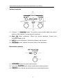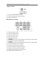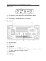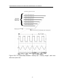
1
100
90
10
0
Digital Storage Oscilloscope
6060S/6060C/6100S/6100C
6150S/6150C/6250S/6250C
Bestell Nr.121830/121831/121832/121833
Bestell Nr.121802/121803/121808/121809
6060S/6060C/6100S/6100C/6150S/6150C/6250S/6250C User Manual
Digital Storage Oscilloscope
6060S/6060C/6100S/6100C/6150S/6150C/6250S/6250C
Bestell Nr.
121830/121831/121832/121833/121802/121803/121808/121809
0
6060S/6060C/6100S/6100C/6150S/6150C/6250S/6250C User Manual
Part No: 82VC-6150SMB
1
6060S/6060C/6100S/6100C/6150S/6150C/6250S/6250C User Manual
Table of Contents
Pages
1. USAGE PRECAUTIONS AND RECOMMENDATIONS ..............................2
2. GENERAL DESCRIPTION AND FEATURES.............................................7
3. FIRST TIME OPERATION ..........................................................................9
4. PANEL DESCRIPTION .............................................................................12
5. OPERATION .............................................................................................17
6. BLOCK DIAGRAM....................................................................................68
7. RS-232 CONFIGURATION .......................................................................69
8. SPECIFICATIONS.....................................................................................72
Due to continuous improvements in the 6060S/C, 6100S/C, 6150S/C and
6250S/C Digital Storage Oscilloscope, information contained in this manual is
subject to change without notice. Contact VOLTCRAFT, for revisions and
corrections.
This document supports firmware version v1.0 for 6060S/C and 6100S/C; firmware version v2.04 for
6150S/C, 6250S/C and previous version
http://www.voltcraft.de
2
6060S/6060C/6100S/6100C/6150S/6150C/6250S/6250C User Manual
1. Usage Precautions and Recommendations
The following precautions are recommended to insure your safety and to provide the
best condition of this instrument. If this equipment is used in a manner not specified
by the manufacture, the protection provided by the equipment may be impaired.
Safety Terms and Symbols
These terms may appear in this manual or on the product:
WARNING: Warning statements identify condition or practices that could
result in injury or loss of life.
CAUTION: Caution statements identify conditions or practices that could
result in damage to this product or other property.
The following symbols may appear in this manual or on the product:
DANGER
ATTENTION
Protective
Frame
Earth (ground)
High Voltage
refer to
Conductor
Terminal
Manual
Terminal
or Chassis
Terminal
3
6060S/6060C/6100S/6100C/6150S/6150C/6250S/6250C User Manual
FOR UNITED KINGDOM ONLY
NOTE: This lead / appliance must only be wired by competent persons
WARNING: THIS APPLIANCE MUST BE EARTHED
IMPORTANT: The wires in this lead are coloured in accordance with the following
code:
Green/ Yellow:
Blue:
Brown:
Earth
Neutral
Live
(Phase)
As the colours of the wires in main leads may not correspond with the colours
marking identified in your plug/appliance, proceed as follows:
The wire which is coloured Green & Yellow must be connected to the Earth terminal
marked with the letter E or by the earth symbol
or coloured Green or Green &
Yellow.
The wire which is coloured Blue must be connected to the terminal which is marked
with the letter N or coloured Blue or Black.
The wire which is coloured Brown must be connected to the terminal marked with
the letter L or P or coloured Brown or Red.
If in doubt, consult the instructions provided with the equipment or contact the
supplier.
This cable/appliance should be protected by a suitably rated and approved HBC
mains fuse: refer to the rating information on the equipment and/or user instructions
for details. As a guide, cable of 0.75mm2 should be protected by a 3A or 5A fuse.
Larger conductors would normally require 13A types, depending on the connection
method used.
Any moulded mains connector that requires removal /replacement must be
destroyed by removal of any fuse & fuse carrier and disposed of immediately, as a
plug with bared wires is hazardous if a engaged in live socket. Any re-wiring must be
carried out in accordance with the information detailed on this lable.
4
6060S/6060C/6100S/6100C/6150S/6150C/6250S/6250C User Manual
Use and Wear
CAUTION
•
Do not exceed 300Vpeak into the channel BNC INPUTs.
•
To avoid risk of fire hazard and electrical shock, a hazardous live voltage must
never be connected to the negative side (reference side) of the BNC measuring
terminals.
•
Do not place any heavy object on the instrument.
•
Avoid severe impacts or rough handling that could damage the oscilloscope.
•
Use electrostatic discharge precautions while handling and making connections
to the oscilloscope.
•
Do not place wires into the connectors of the oscilloscope, only mating
connectors and adapters.
•
Do not block or obstruct cooling fan vent opening on side panels or on the rear
panel of unit.
1) Disassembly of the Instrument
•
Do not disassemble the instrument; refer the instrument to a factory approved
service facility only.
2) AC Power Input
CAUTION
•
•
AC input should be within the range of selected line voltage ±10%.
Insure the correct fuse is installed prior to applying voltage for the first time 100 V ~ 240 VAC input : T 2A / 250V
5
6060S/6060C/6100S/6100C/6150S/6150C/6250S/6250C User Manual
3) Grounding
WARNING
•
To avoid electrical shock, the power cord protective grounding conductor must
be connected to earth ground.
4) Fuse Replacement
WARNING
•
For continued fire protection, replace the fuse with the specified type and rating only.
•
Disconnect power cord before replacing fuse.
•
Open cover of AC socket with flat blade screwdriver.
•
If the fuse is blown, there is something wrong with the instrument. Repair the
cause of fault before replacing fuse.
•
Replace the fuse.
5) Cleaning
•
Disconnect AC Power Cord from the instrument before cleaning.
•
Use a soft cloth dampened in a solution of mild detergent and water.
Do not
spray any liquid into the unit.
•
Do not use chemicals or cleaners containing benzene, toluene, xylene, acetone
or other harsh chemicals.
6
6060S/6060C/6100S/6100C/6150S/6150C/6250S/6250C User Manual
6) Operating Environment
•
The following conditions are recommended for optimum use of the instrument Indoor Use
Altitude < 2000 m
Temperature 0° to 50° C
Relative Humidity < 80%
No direct sunlight
No strong magnetic fields
Dust Free
•
Installation Category:
•
Pollution degree:
II*
2
7) Storage Environment
•
The following conditions are recommended for optimum storage of the
instrument Indoor
Temperature -20° to 70° C
Relative Humidity < 80%
WARNING
This is a Class A product. In a domestic environment this product may cause radio
interference in which case the user may be required to take adequate measures.
*: Measurement category IV is for measurement performed at the source of low-voltage installation
Measurement category III is for measurement performed in the building installation
Measurement category II is for measurement performed on the circuits directly connected to the
low voltage installation
7
6060S/6060C/6100S/6100C/6150S/6150C/6250S/6250C User Manual
2. General Description and Features
The 6060S, 6060C, 6100S, 6100C, 6150S, 6150C, 6250S, and 6250C are the
useful, 2 channel digital storage oscilloscope with following features:
z
Up to 250MHz (60MHz for 6060S/C, 100MHz for 6100S/C, 150MHz for
6150S/C and 250MHz for 6250S/C series) repetitive bandwidth and 100MSa/s
sample rate per channel (25GSa/s E.T. sample rate per channel).
z
Up to 10ns peak detection for glitch capture.
z
A large 5.7” mono or color LCD display (monochrome display for 6060S, 6100S,
6150S and 6250S, color display for 6060C, 6100C, 6150C and 6250C).
z
Two input channels, each with a record length of 125k points and 8 bits vertical
resolution. Both channels acquire waveforms simultaneously.
z
Time base: 1ns/div~10s/div.
z
6-digit trigger frequency counter.
z
Auto-setting for quick setup and hands-free operation.
z
Three Acquisition modes: Sample, peak detect, and average mode.
z
Cursors and 15 continuously update, automatic measurements: Vhi, Vlo, Vmax ,
Vmin , Vpp, Vaverage, Vrms, Vamp , rise time, fall time, duty cycle, frequency, period,
positive width, negative width.
z
15 sets memory for front panel setting save & recall.
z
2 sets memory for waveform trace save & recall.
z
100 sets arbitrary waveforms can be input as templates for Go/NoGo function.
z
FFT spectrum analysis.
z
Two valuable “Program mode” and “Go-No Go” function are included.
z
Advanced video and pulse width trigger.
z
A large 8 ×12 divisions(menu off)waveform display graticule.
z
RS-232, Centronics port, USB output and GPIB interface module are supported.
z
Multi-language operating environment are supported, there are English,
tradition Chinese, simplified Chinese, French, German, Italian, Korean,
Russian, Finnish, Spanish, Polish, and Japanese are supported for this
moment.
8
6060S/6060C/6100S/6100C/6150S/6150C/6250S/6250C User Manual
The advance 32-bit microprocessor controlled digital storage oscilloscope has been
designed for a wide multitude of applications in service and industry. For ease of
operation the “Autoset” function allows for signal related automatic setup of
measuring parameters. On-screen readout and cursor functions for voltage,
frequency
and
frequency
measurement
provide
extraordinary
operational
convenience. Fifteen different user defined instrument settings can be saved and
recalled without restriction. The built-in RS-232 serial interface allows for remote
controlled operation by a PC. A six digits frequency counter provides extra value for
users. The USB port is able to dump entire scope’s LCD screen to computer via
specific software. The valuable “Program” mode is able to help users to record all
the necessary measuring steps and replay all steps again. The special “Go-No Go”
function is very useful for the people who need to distinguish the pass or failure for
particular conditions.
The instrument offer the right combination of triggering control, frequency response,
and time base versatility to facilitate measurements in a wide range of applications
in laboratory as well as in field service use. It is another example of our dedication to
engineering excellence.
9
6060S/6060C/6100S/6100C/6150S/6150C/6250S/6250C User Manual
3. First Time Operation
The following text assumes that the “SAFETY” section of this manual has been read
carefully and understood.
Each time before the instrument is put into operation check that the oscilloscope is
connected to protective earth. For that reason the power cable must be connected to
the oscilloscope and the power outlet. Then the test lead(s) must be connected to
the oscilloscope input(s). Check that the device under test is switched off and
connect the test lead(s) to the test point(s). Then switch on the instrument and
afterward the device under test.
The oscilloscope is switched on by depress the ON/STBY pushbutton (Before
depress the ON/STBY pushbutton of front panel, the main power switch of
rear panel have to be switched on). After a few second the system initiated, the
instrument will revert to its last used operating mode.
Tilt stand this oscilloscope: For desktop use, lock the tilt stand in place as
following figures.
Figure 3-1: Tilts stand this oscilloscope
10
6060S/6060C/6100S/6100C/6150S/6150C/6250S/6250C User Manual
Probe compensation
To display an undistorted waveform on an oscilloscope, the probe must be matched
to the individual input impedance of each vertical amplifier.
For this purpose a square wave signal with a very fast rise time and minimum
overshoot should be used, as the sinusoidal contents cover a wide frequency range.
The build-in compensation signal generator provides a square wave signal with a
very fast rise time, and frequency of approx. 1kHz from the output socket below the
LCD screen. As the square wave signals are used for probe compensation
adjustment, neither the frequency accuracy nor the pulse duty factor are of
importance and therefore not specified.
The output provides 2Vpp±3% for 10:1 probe. When the Y deflection coefficient is set
to 50mV/div, the calibration voltage corresponds to a vertical display of 4 divisions
(10:1 probe).
User checks the waveform indicated correct compensation (see Figure 3-2). If the
waveform indicates over or under compensation, use the alignment tool to adjust the
compensation.
incorrect
correct
incorrect
Figure 3-2: Probe compensations
For 6060S/C and 6100S/C only
6060S/C and 6100S/C provides a valuable “adjustable probe compensation signal
function”. The range for adjustable probe compensation signal is adjusted from 1kHz
to 100kHz, 1kHz per step; and duty cycle is adjusted from 5% to 95%, 5% per step.
This function can satisfy user with the probe compensation easily and accurate.
11
6060S/6060C/6100S/6100C/6150S/6150C/6250S/6250C User Manual
AUTOSET
The “Autoset” function provides a stable, triggered display of any input signal
(almost). User can connect a signal to either the channel 1 or channel 2 input BNC
connectors and press AUTOSET button. Table 3-1 shows the defaults of “Autoset”
function
Table 3-1: Defaults of “Autoset” function
Control
Modified by Autoset
Acquire
Sample
Acquire stop after
RUN/STOP button only
Display style
Vectors
Display format
YT
Horizontal position
Centered within the graticule windows
Horizontal Scale
As determined by the signal frequency
Trigger coupling
DC
Trigger level
Midpoint of data for the trigger source
Trigger position
Center
Trigger slope
Positive
Trigger source
Highest frequency if both channel available
Trigger type
Edge
Vertical bandwidth
Full
Vertical coupling
DC or AC (depend on the signal)
Vertical offset
0V
Vertical scale
As determined by the signal level
12
6060S/6060C/6100S/6100C/6150S/6150C/6250S/6250C User Manual
4. Panel Description
Front Panel
13
6060S/6060C/6100S/6100C/6150S/6150C/6250S/6250C User Manual
Display Area
(1): The memory bar (500 point processed by oscilloscope)*.
(2): Trigger position (T) indicator
(3): Viewable area shows segment of memory bar which been displayed*. Please
refer page 40 for details.
(4): Run/Stop mode indicator
(5): Trigger status
(6): Trigger level indicator
(7): Channel position indicator
(8): Delay trigger indicator
(9): Status display for channel 1 & 2
(10): Sample rate status readout
(11): Horizontal status readout
(12): Trigger source and status readout
(13): Trigger type and mode readout
(14): Acquisition status
(15): Interface type indicator
(16): Trigger Frequency counter
*: The memory bar is always 500 points under RUN mode even the memory
length is selected over 500 points, the oscilloscope is still displaying
250points or 300points (menu off) on LCD screen waveform area.
14
6060S/6060C/6100S/6100C/6150S/6150C/6250S/6250C User Manual
Vertical controls
(1): Channel 1, 2 POSITION knobs. The position control knobs adjust the vertical
position of the channel 1 and channel 2 waveforms
(2): CH1, CH2 Menu pushbutton. Shows the vertical waveform function and
waveform display on/off
(3): MATH function pushbutton. Selects the different math function
(4): VOLTS/DIV knobs. Adjusts the vertical scale of the waveforms.
Horizontal controls
(1): HORI MENU. Select the horizontal functions
(2): Horizontal POSITION knob. Adjust waveforms horizontal position
(3): TIME/DIV knob. Adjusts the horizontal scale of selected waveform
15
6060S/6060C/6100S/6100C/6150S/6150C/6250S/6250C User Manual
Trigger controls
(1): The power ON/STANDBY pushbutton
(2): Selects the trigger type, source and mode
(3): Adjust the trigger level
Miscellaneous controls
(1): Select the acquire modes
(2): Control the display modes
(3): Select the utility functions
(4): Sets the Program mode
(5): Select the cursor types
(6): VARIABLE knob. Multi-function knob which controls many menu functions
(7): Access the 15 automatic measurements.
(8): AUTOSET pushbutton automatically adjusts setup values to track a signal
(9): Printout a hardcopy of the LCD display.
(10): Start and stop oscilloscope acquisition.
(11): Save and recall the setups and waveforms
(12): Erases the stationary waveforms display
(13): Display build-in help files on the LCD screen
(14): Stop the replay for Program mode
16
6060S/6060C/6100S/6100C/6150S/6150C/6250S/6250C User Manual
BNC inputs
(1): The channel 1 & 2 BNC inputs receive electrical signals for display
(2): Ground
(3): Connects with a external trigger signal to oscilloscope
Rear Panel
(1):
(2):
(3):
(4):
(5):
(6):
Main power switch
AC power socket
GPIB port (option)
Fuse drawer
“SELF CAL” output BNC ((DC output :0~±2V).
“GO/NO GO” output BNC (A 10us pulse will generated, 5V Maximum/10mA
TTL output. Please refer to page 46 for details)
(7): USB connector
(8): Printer port
(9): RS-232 port
17
6060S/6060C/6100S/6100C/6150S/6150C/6250S/6250C User Manual
5. Operation
This chapter contains useful information about the operation of this oscilloscope.
Vertical Control
All vertical operations affect the selected waveform. Press the CH1, CH2, or MATH
pushbutton to adjust and select the waveform scale and position.
Figure 5-1: The vertical controls panel
VOLTS/DIV: The VOLTS/DIV knobs adjust the vertical scale (in a 1-2-5 sequence)
of the selected waveforms (channel 1 and channel 2).
POSITION: The position control knobs adjust the vertical position of the channel 1 &
2 waveforms. When the vertical position is adjusted, the channel position indicator
or
(located on the left side of the LCD graticule) will change the position
simultaneously. Besides, the vertical position reached to the vertical border of LCD
graticule, the channel position indicator will change the shape to the “
“
,
,
” or
”. The information of vertical scale will also display on the LCD screen.
(1): If position of channel1 (or channel2) changed, the vertical position readout will
be displayed on here
Figure 5-2: Operating the position knob
18
6060S/6060C/6100S/6100C/6150S/6150C/6250S/6250C User Manual
CH1, CH2: The vertical menu contains the following items when channel 1 or
channel 2 is the selected. These two pushbuttons are also switching the waveform
display of channel 1/channel 2 on or off. If channel one (or channel 2) turned off, the
light of CH1 (or CH2) LED button will be off, and vice versa.
z
Coupling
DC (
/
/
: Press F1 softkey to select AC (
) coupling, or ground (
),
).
z
Invert On/Off: Press F2 softkey to select to turn (waveform) invert on or off
z
Bw Limit On/Off: Press F3 softkey to switch between 20MHz or full bandwidth.
z
Probe 1/10/100: Press F4 softkey to select the probe’s ×1, ×10, or ×100
attenuation.
z
Impedance 1MΩ: Input impedance display. Always 1MΩ input impedance for
this digital storage oscilloscope.
MATH: Select a formula from the math menu: CH1+CH2, CH1-CH2 or FFT (Fast
Fourier Transform). You can convert a time-domain signal into its frequency
components by our advanced FFT math function. The Math menu contains the
following items by pressing F1 softkey after math function is selected. The display of
mathematical waveform can be disabled by pressing MATH pushbutton again.
z
CH1+CH2: Waveform of channel 1 plus waveform of channel 2.
Figure 5-3: Operating the math function (Channel + channel 2)
19
6060S/6060C/6100S/6100C/6150S/6150C/6250S/6250C User Manual
z
CH1-CH2: Waveform of channel 1 minus waveform of channel 2.
The position of CH1+CH2/CH1-CH2 mathematical waveform can be adjusted
by rotating the VARIABLE knob. The math position indicator
(located on the
left side of the LCD graticule) will change the position simultaneously. The
information of mathematical division and unit will also display on the math menu
bar.
z
FFT: The details of FFT operations are following:
FFT
Operation: Push the MATH button to select the FFT function. The Source Channel
and Window algorithm can be selected. Press MATH pushbutton again to disable
FFT spectrum display.
z
Source CH1/CH2: Selects the channel which assigned as the FFT spectrum.
z
Window Rectangular/Blackman/Hanning/Flattop:
z
Window Rectangular: Transform to rectangular windowing mode. This
windowing mode is suitable for transient analysis.
z
Window Blackman: Transform to Blackman windowing mode. The peak
resolution of Blackman windowing is not as fine as Hanning windowing,
however, the response shape flares out less at low levels and rejection of
sidelobes is better.
z
Window Hanning: Transform to Hanning windowing mode. User can
acquire higher frequency resolution by using this windowing mode.
z
Window Flattop: Transform to flattop windowing mode. This mode can
obtain higher magnitude accuracy.
20
6060S/6060C/6100S/6100C/6150S/6150C/6250S/6250C User Manual
z
Position: Adjusts the FFT position on the display area by rotating the
VARIABLE knob. The “ ” math position indicator which located on the left side
of LCD screen is always pointed to 0 dB approximately, where 0dB is defined
as 1Vrms.
z
Unit/div 20/10/5/2/1 dB: Press F5 softkey to expand the FFT spectrum
vertically. Expand factors are 20dB/Div, 10dB/Div, 5dB/Div, 2dB/Div and
1dB/Div.
FFT spectrum measurement by using cursors: FFT spectrum’s magnitude (dB)
and frequency (Hz) can be measured by using cursors. Press CURSOR pushbutton
and select Source MATH by pressing F1 softkey.
z
Source MATH: Selects FFT spectrum cursors measuring function.
z
Horizontal
/
/
/
: Adjust vertical cursors by
rotating the VARIABLE knob. The reference values are also shown on the LCD
screen:
f1: first cursor frequency indication
f2: second cursor frequency indication
△ : The difference value of f1 and f2
Div: frequency per division at present
For more detail operations, please refer to page 60.
z
Vertical
/
/
/
: Adjust horizontal cursors by
rotating the VARIABLE knob. The reference values are also shown on the LCD
screen: The color of two horizontal cursors will be changed to red for the color
oscilloscope.
M1: magnitude indication of first cursor
M2: magnitude indication of second cursor
△ : The difference value of M1 and M2
For more detail operations, please refer to page 60.
21
6060S/6060C/6100S/6100C/6150S/6150C/6250S/6250C User Manual
(1): Cursors measure frequency of input waveform.
(2): The spectrum of channel one input waveform.
(3): Cursors measure magnitude of input waveform.
(4): the readouts for both horizontal and vertical cursors.
Figure 5-4: Operating the math function (FFT) with cursors measurement
22
6060S/6060C/6100S/6100C/6150S/6150C/6250S/6250C User Manual
Horizontal Control
To select the horizontal controls, press the MENU pushbutton to select the features.
Figure 5-5: The horizontal controls panel
TIME/DIV: The TIME/DIV knob adjusts the horizontal scale (in a 1-2-5 sequence) of
the selected waveforms (channel 1 and channel 2).
POSITION: The position control knobs adjust the horizontal position of the channel 1
& 2 waveforms. When the horizontal position is adjusted, the trigger position (T)
indicator “▼” (located on the upper side of the LCD graticule) will change the
position simultaneously. Besides, the horizontal position reached to the horizontal
border of the LCD graticule, the trigger position (T) indicator “▼” will change the
shape to the “τ” or “υ”.
MENU: Select a control to modify the timebase, horizontal position, and horizontal
magnification of selected waveform.
z
Main: Display the main timebase only.
z
Window: To switch between the normal and zoomed display, Press F2 softkey
to display the timebase of windows zoom, in the meantime, the waveform
display area will change to gray color except the zoomed area (see figure 6-6).
Use the TIME/DIV knob to change the length (windows frame time range: from
2ns to one more step faster than the desired timebase. For example, if the 1ms
timebase is selected, the maximum window frame timebase will be 500µs) of
the zone and rotates the horizontal’s POSITION knob to change the position.
23
6060S/6060C/6100S/6100C/6150S/6150C/6250S/6250C User Manual
z
Window Zoom: Press F3 softkey to display the zoomed waveform.
Figure 5-6: Operating the zoom function
z
Roll: Press the F4 softkey to obtain a rolling display similar to a strip-chart
recorder. In the meantime, the system will select the roll mode from “Acquisition
Mode” and the timebase of 200ms/div upper limited automatically.
z
XY: Select XY display format if user want to show channel 1 in horizontal axis
and channel 2 in vertical axis. The XY display controls as following:
The channel 1 VOLTS/DIV knob and vertical POSITION knob controls the
horizontal scale and position.
The channel 2 VOLTS/DIV knob and vertical POSITION knob controls the
vertical scale and position.
24
6060S/6060C/6100S/6100C/6150S/6150C/6250S/6250C User Manual
Figure 5-7: Operating the XY display function
These 500 points processed by the oscilloscope under run mode are characteristic
points of real acquired long memory waveform. Due to the hardware limitation of
LCD panel, always 250 points (300 points for side menu off) will be displayed. The
way to explore the real acquired waveform on the oscilloscope’s long memory is
stopping the scope and change the time base. When the scope is stopped, users
can observe any portion or all the waveform memory record by changing the time
base or horizontal trigger position. Decreasing time base expands the waveform and
is referred to as “zooming in”. This feature performs the similar function to the time
base windowing feature. But this feature is available under the real-time acquisition
mode and is only operable when acquisition is stopped.
Users can shift the stopped waveform horizontally on the LCD screen. It is controlled
by the horizontal’s POSITION knob. Increasing “delay trigger indicator” shifts the
waveform to the left and decreasing “delay trigger indicator” shifts the waveform to
the right. By observing the memory bar and viewable area, user can see what
portion of the memory is being displayed.
The memory length is also an important factor because the following formula.
25
6060S/6060C/6100S/6100C/6150S/6150C/6250S/6250C User Manual
For example, a signal is display on the screen as figure 5-8.
Figure 5-8: The stopped waveform
The sample rate is 250kS/s and the record length is 2500, according the formula we
have
There are 10ms of data in the waveform record. Users may change the “delay
trigger indicator” to observe the total waveform record.
Figure 5-9: Increasing “delay trigger indicator” shifts the waveform to the left
26
6060S/6060C/6100S/6100C/6150S/6150C/6250S/6250C User Manual
Figure 5-10: Decreasing “delay trigger indicator” shifts the waveform to the right
The sum of left-most “delay trigger indicator” and right-most “delay trigger indicator”
is equal to 10ms (5ms+5ms). Therefore, the above formula is approved.
The maximum “exploring” factor for this oscilloscope is 7 faster “time/div” setting on
the sample rate of original acquired waveform. In the meantime, the “exploring”
factor is only based on the 500 points of memory length.
Users should check the sample rate in advance, and examine Table 5-2 (the row of
memory length=500) to find out the interrelated timebase afterward. After the
interrelated timebase is confirmed, just count 7 faster “time/div” setting from Table 52. The maximum “exploring” factor is appeared. In an easy way, users may just
rotate the horizontal’s TIME/DIV knob directly. The oscilloscope will count
automatically.
27
6060S/6060C/6100S/6100C/6150S/6150C/6250S/6250C User Manual
For example, the sample rate of figure 5-8 is 250kSa/s. The 250kSa/s on memory
length 500 is 100μs/s according to Table 5-2. Therefore, the maximum expand
time/div will be “500ns/s”.
Figure 5-11: The maximum “zooming in” factor for 250kSa/s sample rate is 500ns/s
The viewable area is also adjusted properly for the varying of “exploring” factor.
28
6060S/6060C/6100S/6100C/6150S/6150C/6250S/6250C User Manual
Trigger Control
When the instrument starts acquiring and display a waveform, “trigger” help create
meaningful waveforms from unstable jumbles or blank screen. To access the
triggering controls, press trigger MENU key, the trigger menu will provide the Type,
SOURCE, MODE, or SLOPE/COUPLING soft key to select the features.
Figure 5-12: Trigger controls
Type (Edge/Video/Pulse/Delay): The F1 softkey provides four different kinds
trigger type: Edge, video, pulse and delay.
Type Edge: Select edge triggering to trigger on the input signal’s edge.
SOURCE: Select the trigger source.
z
CH 1: Select channel 1 as trigger source.
z
CH 2: Select channel 2 as trigger source.
z
External: Select “EXT TRIG” BNC input as trigger source. Note this instrument
can trigger on external trigger signals, but cannot display them.
z
Line: Select AC line voltage signal as trigger source.
MODE: Select a trigger mode.
z
Auto Level: Press F3 softkey to enable the auto level triggering. In this mode,
the adjusting of “trigger level indicator” will be limited only between the top and
bottom of input waveform. If the “trigger level indicator” adjusted over the range,
the oscilloscope will shift the “trigger level indicator” to the central part of
waveform automatically. External trigger is not support under this mode.
29
6060S/6060C/6100S/6100C/6150S/6150C/6250S/6250C User Manual
z
Auto: In this mode, the oscilloscope will generate an internal trigger in the
absence of other trigger events. Also, select Auto trigger mode when you want
an un-triggered, rolling waveform at 250ms/div or slower timebase settings. This
mode is able to continuously observe low speed phenomena in real time down
to a speed of 10s/div.
z
Normal: Normal trigger mode enables the oscilloscope to acquire a waveform
only when instrument is triggered. If no trigger occurs, the instrument will not
acquire waveform.
z
Single: Press F3 softkey to trigger on the next valid trigger event and then stop.
If a trigger is required again, just press the RUN/STOP pushbutton. Signal shot
events are waveforms that happen only once or infrequently. In order to capture
a signal shot events, user needs to have knowledge of the waveform, which is
trying to capture. Before user can setup the trigger, vertical, and horizontal
controls to capture and display event, user must know the approximate
amplitude, duration, and DC offset of the signal.
The trigger status (Page 13, item 5) indicates the following:
Trig’d: The oscilloscope displays acquired waveform only after all of the trigger
conditions are met.
Trig?: The absence of triggers for normal and single mode.
Figure 5-13: The absence of triggers for normal and single mode
30
6060S/6060C/6100S/6100C/6150S/6150C/6250S/6250C User Manual
AUTO: The oscilloscope is in auto mode and trigger conditions are not met.
Figure 5-14: The oscilloscope is in auto mode and trigger conditions are not met
SLOPE/COUPLING: Change trigger slope and select trigger coupling by pressing
F5 softkey.
z
Slope
: Press the F1 softkey to select the triggering slope; oscilloscope
will change the “trigger slope” to the rising or falling edge.
z
Coupling DC/AC: Press the F2 softkey to select DC coupling (
coupling (
) or AC
).
z
Rejection LF/HF/Off: Press F3 softkey to select the frequency reject mode.
z
LF: Press the F3 softkey to enable low frequency reject mode. Low frequency
reject mode removes the low frequency portion of the triggering signal. That
allows only the high frequency components to pass on to the triggering system
and start an acquisition afterward. Low frequency rejection attenuates signals
below 50kHz.
z
HF: High frequency reject mode does the opposite of low frequency reject
mode. High frequency rejection attenuates signals above 50kHz.
31
6060S/6060C/6100S/6100C/6150S/6150C/6250S/6250C User Manual
z
z
: Switch off frequency reject mode.
Noise Rej On/Off: Press F4 softkey to enable noise reject mode. Noise reject
mode provides lower DC sensitivity. It requires additional signal amplitude for
stable triggering, reducing the change of falsely triggering on noise.
z
Previous Menu: Back to previous menu.
Video Triggering
Press F1 softkey can select video triggering.
z
Type Video: The video trigger gives user a variety of selections for triggering
on video signals: the selection of NTSC, PAL or SECAM video signal; polarity;
line, field 1 or field 2.
z
SOURCE: Select the channel 1 or channel 2 as trigger source.
z
Standard NSTC/PAL/SECAM: Press F3 softkey to select predefined setups
(NSTC, PAL or SECAM). NSTC has a line rate of 525 lines per frame and a
field rate of 60Hz. PAL and SECAM have a line rate of 625 lines per frame and
a field rate of 50Hz.
z
Polarity
: The video trigger can trigger on the negative- going
sync pulses (default). If need to trigger on positive-going sync of a signal, simply
invert the signal by pressing F4 softkey again.
z
Field 1/Field 2/Line:
z
Field 1: Press F5 softkey to trigger on field 1 of the video signal. Rotate the
VARIABLE knob to display the specific line. (The adjustable line range for
NSTC: 1~263; for PAL/SECAM: 1~313)
32
6060S/6060C/6100S/6100C/6150S/6150C/6250S/6250C User Manual
z
Field 2: Press F5 softkey to trigger on field 2 of the video signal. Rotate the
VARIABLE knob to display the specific line (The adjustable line range for
NSTC: 1~262; for PAL/SECAM: 1~312)
z
Line: Press F5 softkey to trigger on all lines of the video signal
Figure 5-15: Vide trigger mode
33
6060S/6060C/6100S/6100C/6150S/6150C/6250S/6250C User Manual
Pulse Width Triggering
z
Type PULSE: The pulse width triggering can provide the scope to trigger on a
negative or positive pulse of a specified width. The range of pulse width can be
adjusted form 20ns until 10 second. The relations for pulse width, pre scale and
pulse width count are shown on Table 5-1.
Pulse Width
Pre scale
Pulse width count
20ns~980ns
1.00us~9.98us
10us~99.9us
100us~999us
1.00ms~9.99ms
10.0ms~99.9ms
100ms~999ms
1.00s~10.0s
20ns
20ns
20ns
200ns
200ns
2000ns
20000ns
200000ns
1~49
50~499
500~4995
500~4995
5000~49950
5000~49950
5000~49950
5000~50000
Table 5-1
z
SOURCE: Select the input channel as trigger source.
z
Mode: Select different triggering types.
z
When <>=≠: Press F4 softkey to select the different time compare factor.
z
When <: When the less than “<” time compare factor selected, the
VARIABLE knob sets the scope to trigger on a pulse width less than the time
value displayed on the F4 softkey.
z
When >: When the greater than “>” time compare factor selected, the
VARIABLE knob sets the scope to trigger on a pulse width greater than the
time value displayed on the F4 softkey.
z
When =: When the equal “=” time compare factor selected, the VARIABLE
knob sets the scope to trigger on a pulse width equal to the time value
displayed on the F4 softkey.
z
When ≠: When the unequal “≠” time compare factor selected, the
VARIABLE knob sets the scope to trigger on a pulse width unequal to the time
value displayed on the F4 softkey.
34
6060S/6060C/6100S/6100C/6150S/6150C/6250S/6250C User Manual
z
Slope
: Select positive or negative polarity for the pulse width triggering.
(1): When positive polarity selected, the trigger will take place on the high to low
transition of the pulse if the compare condition is match. See figure 5-10.
(2): When negative polarity selected, the trigger will take place on the low to
high transition of the pulse if the compare condition is match. See figure 5-11
Figure 5-16: Pulse width trigger with positive polarity selected
Figure 5-17: Pulse width trigger with negative polarity selected
35
6060S/6060C/6100S/6100C/6150S/6150C/6250S/6250C User Manual
z
Coupling DC/AC: Press the F2 softkey to select DC coupling or AC coupling.
z
Rejection LF/HF/Off: Press F3 softkey to switch off the frequency reject mode.
z
Previous Menu: Back to previous menu.
Advance Triggering
z
Type Delay: The advance delay trigger system includes a start trigger signal
and a 2nd trigger source (main trigger). The start trigger signal generated from
external trigger. When using the advance trigger system, user can delay the
acquisition of a waveform for a user-defined time or a user-defined number of
delayed trigger events after a start trigger signal. Press the F2, F3, and F4
softkey to select three advance delay trigger settings: By Time, By Event, and
TTL/ECL/USER.
z
By Time: After the specified user-defined delay timer times out (from external
trigger), the oscilloscope will triggers on the edge which been specified. Rotate
the VARIABLE knob to select the specific delay time. (The adjustable delay
time range: 100ns~1.3ms).
If the external trigger is applied, the true trigger will be applied by the CH1 (or
CH2) trigger after the elapse of set time.
Trigger
Start trigger
(From external)
Set time (T)
Main trigger
(From CH1 or CH2)
Trigger Point
Figure 5-18: The start trigger signal is ignored during the set time interval (T); the
start trigger signal caused first after elapse of the set time (T) becomes a trigger
point.
36
6060S/6060C/6100S/6100C/6150S/6150C/6250S/6250C User Manual
If start trigger signal is selected, the DELAY time can be set by the VARIABLE
knob.
If the main trigger is selected, presses the F4 softkey to select the start trigger
signal level from the following three levels.
TTL: This is the mode for the TTL signal measurement and start trigger signal
are set to +1.4V.
ECL: This is the mode for the ECL signal measurement and start trigger signal
are set to -1.3V.
USER: Select USER mode and rotate the VARIABLE knob to define the
specific start trigger signal level. (The adjustable start trigger signal level range:
±12V)
Note: All accuracy of these signals’ level are based on the probe ×1 only
z
By Event: Waits the user-defined delay trigger events and then acquires.
Rotate the VARIABLE knob to select the specific delay event. (Numbers of
events: 2~65000)
Trigger
Start trigger
(From external)
Main trigger
(From CH1 or CH2)
1
Start of external trigger
count
2
3
Trigger Point
Figure 5-19: Event delay trigger. Number of set event: In case of three.
37
6060S/6060C/6100S/6100C/6150S/6150C/6250S/6250C User Manual
If start trigger signal is selected, the number of events can be selected by the
VARIABLE knob.
If the main trigger is selected, press the F4 softkey and to select the start trigger
signal level from the following three levels.
TTL: This is the mode for the TTL signal measurement and start trigger signal
are set to +1.4V.
ECL: This is the mode for the ECL signal measurement and start trigger signal
are set to -1.3V.
USER: Select USER mode and rotate the VARIABLE knob to define the
specific start trigger signal level. (The adjustable start trigger signal level range:
±12V)
Note: All accuracy of these signals’ level are based on the probe ×1 only
38
6060S/6060C/6100S/6100C/6150S/6150C/6250S/6250C User Manual
Miscellaneous Controls
To select the miscellaneous controls, press these pushbuttons to select specific
features (see Figure 5-12).
Figure 5-20: Miscellaneous controls
ACQUIRE: Press ACQUIRE pushbutton to select the different acquire mode:
Sample, Peak-Detect, and Average. Acquisition is the process of sampling the
analog input signal and converting it into digital format afterward, assembling it into a
waveform record finally.
z
Sample: Press F1 to select the “sample” acquisition mode. In sample mode,
the instrument generates a record point by saving the first sample during each
acquisition interval.
z
Peak-Detect: The “Peak-Detect” mode stores the minimum and maximum
values (pairs) for each acquisition intervals. Use Peak-Detect acquisition mode
which can detect glitches as narrow as 10ns and the aliasing can be limited
possibly. This mode is effective when the horizontal scale (SEC/DIV) setting
from 500ns/div to 10s/div
z
Average: The average mode selects the number of waveform acquisitions that
are averaged to generate the display waveform. The range for the averaging is
from 2 to 256 in powers of 2.
Note: The number select of “average” only effectiveness on the record
lengths of 500.
39
6060S/6060C/6100S/6100C/6150S/6150C/6250S/6250C User Manual
Average mode reduces displayed signal noise significantly. As the number of
averages increases from 2 to 256, the display becomes less responsive to
changes in the input signal. Using more averages reduces the effects of
displayed signal noise and improves resolution.
If any of the record lengths (except record lengths of 500) and average
number been selected (for this moment, the selection of average number is
ineffective), the instrument will use the resolution improved technology to
average entire waveform by different acquisition intervals automatically.
Therefore, user can get an average result in a higher sample rate, and better
resolution waveform.
Note: The different between record lengths of 500 and the rest is the
“sampling”. If the “record lengths” is selected to 500, the sampling will be
triggered individually. If “record lengths” is the rest number, the sampling
is triggered for once.
z
Men Leng: The number of points that make up the waveform record is defined
by record length. This oscilloscope provides record lengths of 500, 1250, 2500,
5000, 12500, 25000, 50000, and 125000. For the relationship between memory
length, timebase, and sample rate, please refer to Table 5-2. To ensure a full
screen display of 500 points on the slower timebase ranges, as the timebase is
slowed down the sample rate is also slowed down.
The relationship between memory bar, viewable area, and memory length
setting are shown on Figure 5-21 and 5-22. The memory bar is always
indicating the selected memory length but be compressed into 500 points. The
viewable area will display 250 points, if the side menu turned on. If the side
menu is turned off, the viewable area should display 300 points.
The entire 125k acquisition memory can be dumped to personal computer for
further data analysis. Please refer to programming manual for details.
40
6060S/6060C/6100S/6100C/6150S/6150C/6250S/6250C User Manual
Figure 5-21: The relationship between “memory bar”, “memory length”, and
“viewable area (menu on)”
41
6060S/6060C/6100S/6100C/6150S/6150C/6250S/6250C User Manual
Figure 5-22: The relationship between “memory bar”, “memory length”, and “viewable area (menu off)”.
42
6060S/6060C/6100S/6100C/6150S/6150C/6250S/6250C User Manual
Memory
length
500
1250
2500
5000
12500 25000 50000 125000
Timebase
1ns/div
ET25Gsa/s
NA
NA
NA
NA
NA
NA
NA
2.5ns/div
ET10Gsa/s
NA
NA
NA
NA
NA
NA
NA
5ns/div
ET5Gsa/s
NA
NA
NA
NA
NA
NA
NA
10ns/div
ET2.5Gsa/s
NA
NA
NA
NA
NA
NA
NA
25ns/div
ET1Gsa/s
NA
NA
NA
NA
NA
NA
NA
50ns/div
ET500Msa/s
NA
NA
NA
NA
NA
NA
NA
100ns/div
ET250Msa/s
NA
NA
NA
NA
NA
NA
NA
250ns/div
100MSa/s
NA
NA
NA
NA
NA
NA
NA
500ns/div
50MSa/s
100MSa/s
NA
NA
NA
NA
NA
NA
1µs/div
25MSa/s
50MSa/s 100MSa/s
NA
NA
NA
NA
NA
2.5µs/div
10MSa/s
25MSa/s 50MSa/s 100MSa/s
NA
NA
NA
NA
5µs/div
5MSa/s
10MSa/s 25MSa/s 50MSa/s 100MSa/s
NA
NA
NA
10µs/div
2.5MSa/s
NA
NA
25µs/div
1MSa/s
50µs/div
500kSa/s
1MSa/s 2.5MSa/s 5MSa/s 10MSa/s 25MSa/s 50MSa/s 100MSa/s
100µs/div
250kSa/s
500kSa/s 1MSa/s 2.5MSa/s 5MSa/s 10MSa/s 25MSa/s 50MSa/s
250µs/div
100kSa/s
250kSa/s 500kSa/s 1MSa/s 2.5MSa/s 5MSa/s 10MSa/s 25MSa/s
500µs/div
50kSa/s
100kSa/s 250kSa/s 500kSa/s 1MSa/s 2.5MSa/s 5MSa/s 10MSa/s
1ms/div
25kSa/s
50kSa/s 100kSa/s 250kSa/s 500kSa/s 1MSa/s 2.5MSa/s 5MSa/s
2.5ms/div
10kSa/s
25kSa/s 50kSa/s 100kSa/s 250kSa/s 500kSa/s 1MSa/s 2.5MSa/s
5ms/div
5kSa/s
10kSa/s 25kSa/s 50kSa/s 100kSa/s 250kSa/s 500kSa/s 1MSa/s
10ms/div
2.5kSa/s
5kSa/s
25ms/div
1kSa/s
2.5kSa/s
5kSa/s
50ms/div
500Sa/s
1kSa/s
2.5kSa/s
5kSa/s
100ms/div
250Sa/s
500Sa/s
1kSa/s
2.5kSa/s
5kSa/s
250ms/div
100Sa/s
250Sa/s 500Sa/s
1kSa/s
2.5kSa/s
5kSa/s
500ms/div
50Sa/s
100Sa/s 250Sa/s 500Sa/s
1kSa/s
2.5kSa/s
5kSa/s
10kSa/s
1s/div
25Sa/s
50Sa/s
100Sa/s 250Sa/s 500Sa/s
1kSa/s
2.5kSa/s
5kSa/s
2.5s/div
10Sa/s
25Sa/s
50Sa/s
100Sa/s 250Sa/s 500Sa/s
1kSa/s
2.5kSa/s
5s/div
5Sa/s
10Sa/s
25Sa/s
50Sa/s
100Sa/s 250Sa/s 500Sa/s
10s/div
2.5Sa/s
5Sa/s
10Sa/s
25Sa/s
50Sa/s
5MSa/s 10MSa/s 25MSa/s 50MSa/s 100MSa/s
2.5MSa/s 5MSa/s 10MSa/s 25MSa/s 50MSa/s 100MSa/s
NA
10kSa/s 25kSa/s 50kSa/s 100kSa/s 250kSa/s 500kSa/s
10kSa/s 25kSa/s 50kSa/s 100kSa/s 250kSa/s
10kSa/s 25kSa/s 50kSa/s 100kSa/s
10kSa/s 25kSa/s 50kSa/s
10kSa/s 25kSa/s
1kSa/s
100Sa/s 250Sa/s 500Sa/s
Table 5-2: The available sample rate between different timebase and memory length.
43
6060S/6060C/6100S/6100C/6150S/6150C/6250S/6250C User Manual
DISPLAY: Press the DISPLAY pushbutton to change the appearance of the display
and select how waveforms are presented.
Note: Always 250 points plotted to screen on each acquisition.
Type Vector/Dot:
z
Type Vector: Press the F1 softkey to select vector display style. The instrument
draws a vector between each pair of waveform points.
z
Type Dot: Displays only the individual sample points.
z
Accumulate (On/Off): The “Accumulate” mode can acquire and display a
waveform record that shows the totally variation over entire acquisitions.
z
Refresh: Press F3 softkey to refresh the waveforms.
z
Contrast (0~100%): Press F4 softkey to adjust the contrast of LCD screen. Use
the VARIABLE knob to vary LCD screen contrast.
For 6060S/C and 6100S/C only:
: Rotate the VARIABLE knob to vary LCD screen contrast. Rotating
clockwise is increasing the contrast; Rotating counter-clockwise is decreasing
the LCD contrast.
z
: Press F5 softkey to select three different graticular
display mode.
z
: Only X and Y axial are displayed.
z
: Only outer frame is displayed.
z
: Full grids are displayed
44
6060S/6060C/6100S/6100C/6150S/6150C/6250S/6250C User Manual
UTILITY: The utility menu provides abundant sub menus: Printer menu, Interface
menu,
(Beep), Language, self-cal menu, System Inform, Go-No Go
menu, and No Go When.
z
Printer Menu: If a printer is connected and properly configured, 6060S/C,
6100S/C, 6150S/C, and 6250S/C can print a hard copy of the LCD display.
Press F1 softkey again to select printer. This oscilloscope supports the following
printers:
z
Type HP: Both Hewlett-Packard’s LaserJet laser printers and DeskJet
inkjet printers supported.
Press the pushbutton of HARDCOPY pushbutton to start printing from any time
after printer is properly configured.
Note: This oscilloscope do not support any GDI printers.
Note: The USB of this oscilloscope is “DEVICE” only, this oscilloscope
DO NOT support any USB printers.
z
Interface Menu: This oscilloscope can transfer data between the scope and
other instrument over the RS-232, USB, or GPIB interface. Press F1 softkey to
select the GPIB location.
For RS232 setup
z
Type RS232: Select RS-232 communication port.
z
Baud rate: Transmission rate in characters per second. Transmission rate
selections are: 2400, 4800, 9600, 19200, and 38400 baud.
z
Stop bit: Press the adjacent pushbutton to select “1” or “2” bits.
z
Parity: Press the adjacent pushbutton to select “Odd”, “Even”, or “None”.
z
Previous Menu: back to previous menu.
Note: The “Data Bit” is always 8-bit.
45
6060S/6060C/6100S/6100C/6150S/6150C/6250S/6250C User Manual
For USB
z
Type USB: Select USB port.
Note: In order to display the real-time waveform on personal computer,
please download the “FreeView” communication software from our
website http://www.voltcraft.de.
z
Previous Menu: back to previous menu.
For GPIB
z
Type GPIB: Select GPIB port.
z
Addr 1~30: select the appropriate address for GPIB.
z
Previous Menu: back to previous menu.
z
z
: Select the tone for build-in buzzer.
z
: Select the tone in higher frequency.
z
: Select the tone in lower frequency.
z
: Select the tone in mixed frequency.
z
: Turn off the buzzer.
Language Menu: English, tradition Chinese, simplified Chinese, French,
German, Italian, Korean, Russian, Finnish, Spanish, Polish, and Japanese are
supported for this moment.
z
More: press F5 softkey to other utilities.
46
6060S/6060C/6100S/6100C/6150S/6150C/6250S/6250C User Manual
z
Self Cal Menu: Please refer to service menu for the details.
z
System Inform: The company name, model name, and firmware version will be
shown on the LCD screen.
z
Go- No Go Menu: The Go- No Go judgment function can be used to judge if
the acquired signal is matched with the pre-save patterns. The input waveforms
are compared with the pattern and the measured waveform is evaluated to
automatically determine which action to perform. The following actions can be
selected based on this evaluation:
1. The build-in buzzer.
2. The “Go-No Go” BNC connector on the rear.
The level of output signals from “Go-No Go” BNC connector is defined as
following:
If the result is “Good”, the output level is remained in low level.
If the result is “No Good”, a 10us pulse (5V Maximum/10mA TTL output) will be
generated to the “Go-No Go” BNC connector.
Note: The signal of “Go-No Go” BNC connector is “open collect”.
z
Template Edit: Edits the proper templates. Press F1 softkey once and
enter to sub-menu (Max/Min/Auto).
For Template Max and Min
z
Template Max/Min: The “Go-No Go” templates are selected from
Reference A or B of “Save/Recall” function, for the details operation, please
refer to page 58.
Template Max: The maximum template is always selected from the
Reference A of “Save/Recall” function or from the one hundred sets of
custom-made waveforms.
47
6060S/6060C/6100S/6100C/6150S/6150C/6250S/6250C User Manual
Template Min: The minimum template is always selected from the
Reference B of “Save/Recall” function or from the one hundred sets of
custom-made waveforms.
Note: The maximum and minimum templates can not select the same
custom-made waveform source. For example, if the custom-made
waveform of “Template Max” is selected as number 10, the “Template
Min” have to choice the different custom-made waveform number except
number 10.
z
Source RefA/RefB/1~100: Indication for the source of maximum
template or minimum template (Reference A for maximum template;
Reference B for minimum template).
This oscilloscope can accept one hundred custom-made waveforms (only
available after firmware version 2.03 for 6150S/C and 6250S/C;
available for 6060S/C and 6100S/C all firmware versions) from a
personal computer with the advance “FreeCapture” software (this freeware
can be downloaded from our website: http://www.voltcraft.de ). The
“FreeCapture” software can edit any specified waveforms from users and
input to oscilloscope as maximum (or minimum) templates. The maximum
custom-made waveforms input capacities are one hundred sets. For the
details of “FreeCapture” operations, please refer to the “FreeCapture”
operation manual.
User can select the different custom-made waveforms sets by rotating the
VARIABLE knob. The maximum or minimum template CAN NOT select the
identical custom-made waveforms location. The two maximum and
minimum must be selected form the different custom-made waveforms
location. Otherwise, the “Go- No Go” function will go wrong.
z
Position: Adjust the vertical position for maximum template or
minimum template or custom-made waveforms. The adjustable ranges are
from ±0.04 division to ±4 division.
48
6060S/6060C/6100S/6100C/6150S/6150C/6250S/6250C User Manual
z
Save: Press F4 softkey to save the current settings. In the meantime,
the original saved reference A or B from “Save/Recall” function will be also
changed as current setting.
z
Previous Menu: back to previous menu.
For Template Auto
z
Template Auto: The two “Go-No Go” templates are generated
automatically from the subject signal.
(1): According to the subject signal, the two templates (RefA and RefB) are
created
by
“Template
Auto”
automatically.
The
adjustable
range
(Tolerance) is available from ±0.4% to ±40% (or ±0.04 division to ±4
division).
Figure 5-23: Template created “Template Auto” function
z
Source CH1/CH2: Select the input source of channel 1 or channel 2
as “Go-No Go” template.
z
Tolerance %: Select the tolerance percentage (or division) range for
vertical and horizontal scales from the subject signal. The adjustable range
is available from ±0.4% to ±40% (or ±0.04 division to ±4 division).
49
6060S/6060C/6100S/6100C/6150S/6150C/6250S/6250C User Manual
z
Save & Create: Press F4 softkey to save the settings. In the
meantime, the original saved reference A or B from “Save/Recall” function
will be also changed as current setting
Previous Menu: Back to previous menu.
z
Source: select channel 1 or channel 2 as subject signal input.
z
Violating Stop/
/Continue/
: Select the process after
subject is violating the compared templates.
Violating Stop: If subject signal is judged to be “No Good”, the “Go-No
Go” function will stop. The counts of violation will be recorded.
Violating
: If subject signal is judged to be “No Good”, the “Go-No
Go” function will stop and oscilloscope will beep once. The counts of
violation will be recorded.
Violating Continue: If subject signal is judged to be “No Good”, the “GoNo Go” function will to be executed continually. The counts of violation will
be recorded.
Violating
: If subject signal is judged to be “No Good”, the “Go-No
Go” function will be executed continually and oscilloscope will beep once.
The counts of violation will be recorded.
Note: All the judgment condition are based on the setting of No Go
When
/
. See next page for details.
z
Go- NoGo On/Off: Starts the “Go- No Go” function.
z
Ratio :: Display the counts of “Go-No Go” test and failure. Press F5 softkey
to reset the counts of ratio to zero.
Press any pushbutton to exit the “Go-No Go” function.
50
6060S/6060C/6100S/6100C/6150S/6150C/6250S/6250C User Manual
z
No Go When
/
: Select the judgment condition of violation for
“Go-No Go” function.
z
No Go When
: If the subject signal is not violating the templates,
the system will judge such condition as “No Go” situation by selecting this
function.
z
No Go When
: If the subject signal is violating the templates, the
system will judge such condition as “No Go” situation by selecting this function.
z
More: Press F5 softkey to other utilities.
CAL. OUTPUT: The adjustable signal output provides a range for a signal of
probe compensation which can be adjusted from 1kHz to 100kHz, 1kHz per
step; and duty cycle is adjusted from 5% to 95%, 5% per step. This function can
satisfy user with the probe compensation more easily and accurately. NOTE:
This function is available for 6060S/C and 6100S/C only
Figure 5-24: The menu for adjustable probe compensation signal
z
Wave Type: Press F1 soft key to select adjustable probe compensation
signal or another two output signals for demonstration.
: A demonstration signal which designed for the purpose of long record
length.
: A demonstration signal which designed for the purpose of peak
detects.
51
6060S/6060C/6100S/6100C/6150S/6150C/6250S/6250C User Manual
z Frequency: The adjustable frequency range for probe compensation signal
is from 1kHz to 100kHz, at 1kHz per step.
z Duty Cycle: The adjustable duty cycle range for probe compensation
signal is from 5% to 95%, at 5% per step.
z Default 1k: Press F4 soft key to output a 1k probe compensation signal.
NOTE: Always use 1k probe compensation signal to compensate the
probes, DO NOT use another frequencies except 1k to compensate the
probes.
z Previous Menu: Press F5 softkey to previous menu.
52
6060S/6060C/6100S/6100C/6150S/6150C/6250S/6250C User Manual
PROGRAM: The advance “Program mode” function is able to let oscilloscope to
remember certain steps and replay all the saved steps. There are two main
operating classes for “Program mode”: Edit and Play. Users can edit preferred
operating steps and replay all of the saved steps afterward.
Figure 5-25: Press PROGRAM pushbutton and enter to “Program” mode
Steps Editing:
z
Edit: Begin to edit entire steps. Press F1 softkey again will go to replaying
mode.
z
Step 1-15: Select the step which to be edited and rotate the VAIABLE knob to
select the preferred step. The setting of range is from 1 to 15.
z
Item Memory/Menu/Time: Select the conditions for each step. Press the F3
softkey continually to select three different conditions: Item Memory, Item Menu,
and Item Time.
z
Item Memory: Select one of the pre-saved waveform from fifteen internal
memory sets. Rotates the VARIABLE knob to pick proper memory set. The presaved memory is available from memory one to memory fifteen (M1~M15).
z
Item Menu: Select which menu to be shown on the LCD panel for present
step running. Only two menus can be displayed during “Program Mode”
running, the two menus are measurement and cursor menu. Rotates the
VARIABLE knob to select preferred display menu.
53
6060S/6060C/6100S/6100C/6150S/6150C/6250S/6250C User Manual
z
Item Time: Select the time of stop. The selectable range: 1~99 seconds.
Or wait users to press Run/Stop pushbutton and stop the present replaying
step.
z
Save: Press F5 softkey to save current steps of Program mode.
Steps Replaying:
z
Play: Settings for replaying of saved steps.
z
Cycle 1~99: The Program mode procedure can be replayed from 1 to 99 times
repetitiously.
z
From/To: Select any step of “Program mode” to be the first replay step and the
final replay step.
z
Start: Press F5 softkey to start replaying the “Program mode”.
Press Auto test/Stop pushbutton to quit the “Program mode”.
Figure 5-26: Programming for play function of “Program” mode
(1): The starting step indicator for replaying.
(2): The final step indicator for replaying.
54
6060S/6060C/6100S/6100C/6150S/6150C/6250S/6250C User Manual
Figure 5-25 shows a program which replay form step one to step six and run ten
times repetitiously.
The first step is the settings which recalled form the memory one (M1), the “Auto
Measurement” menu will be displayed on the LCD screen during step one replaying;
the running time is three seconds.
The final step (step six) is recalled form sixth memory location (M6), the “Cursor”
menu will be displayed on the LCD screen during step six replaying; the running time
is controlled by pressing the Auto test/Stop pushbutton.
Example: editing a 2-step “program” which included two different signal input and
monitoring the Vpp, Vavg, Frequency, duty cycle and rise-time. This program should
be repeated five times, 10 seconds for each step.
1. The input for channel one is a 2Vpp, 10kHz sine wave from beginning; (a). Press
CURSOR button and F3 softkey to enable vertical cursors; (b). Adjusting the two
cursors to proper position by rotating the VARIABLE knob.
Figure 5-27: Adjusting the vertical position for channel one input of example
55
6060S/6060C/6100S/6100C/6150S/6150C/6250S/6250C User Manual
2. Save all settings of channel one to memory location one (M 01). (a). Press
SAVE/RECALL button and F3 softkey to select memory location; select memory
location one (M 01) by rotating the VARIABLE knob. (b). Press F4 softkey to
save the channel one settings.
Figure 5-28: Save channel one settings to memory location one (M 01)
3. The input for channel two is a 6Vpp, 1MHz square wave; (a). Press CURSOR
button and F1 softkey to select channel tow as source; (b). Press F2 and F3
softkey to enable horizontal and vertical cursors; (c). Adjusting the two cursors to
proper position by rotating the VARIABLE knob.
Figure 5-29: Adjusting the horizontal and vertical position for channel two inputs
56
6060S/6060C/6100S/6100C/6150S/6150C/6250S/6250C User Manual
4. Save all settings of channel two to memory location two (M 02). (a). Press
SAVE/RECALL button and F3 softkey to select memory location; select memory
location one (M 02) by rotating the VARIABLE knob; (b). Press F4 softkey to
save the channel two settings afterward.
Figure 5-30: Save channel two settings to memory location two (M 02)
5. Press PROGRAM button to enter program mode.
Figure 5-31: Enter to program mode
57
6060S/6060C/6100S/6100C/6150S/6150C/6250S/6250C User Manual
6. (a). Press F2 softkey and rotate the VARIABLE knob to select “step 1”; (b).Press
F3 softkey to select “Item Memory” and rotate the VARIABLE knob to select
memory location one (M1) ; (c). Press F3 softkey again to select “Item Menu”
and rotate the VARIABLE knob to select AutoMeasure menu; (d). Press F3
softkey again to select “Item Time” and rotate the VARIABLE knob to select 10
seconds operation interval for step one.
Figure 5-32: Editing the program condition of step one
7. (a). Press F2 softkey to skip into “step 2”; (b).Press F3 softkey to select “Item
Memory” and rotate the VARIABLE knob to select memory location two (M2);
(c). Press F3 softkey again to select “Item Menu” and rotate the VARIABLE knob
to select AutoMeasure menu; (d). Press F3 softkey again to select “Item Time”
and rotate the VARIABLE knob to select 10 seconds operation interval for step
two.
Figure 5-33: Editing the program condition of step two
58
6060S/6060C/6100S/6100C/6150S/6150C/6250S/6250C User Manual
8. The steps of program condition are completed now. And we need (a). Press F5
softkey to save all steps on system. (b). Press F1 softkey to “Program Play”
menu; (c.) Press F2 softkey to select running cycle for program and rotate the
VARIABLE knob to select the operation repeated cycle. We select 5 times here;
(d). Press F3 softkey and rotate the VARIABLE knob to select to select the
starting step. The step one is selected as starting step here; (e). Press F3
softkey again and rotate the VARIABLE knob to select to select the last step for
entire program. The step two is selected as the last step here. (f). Press F3
softkey again to complete the settings. A
“the end” marker will be displayed
on the place of step two.
Figure 5-34: Editing the playing time condition
9. Now, we can press F5 softkey to start the program.
Figure 5-35: step one is continual running for 10 seconds on program mode
59
6060S/6060C/6100S/6100C/6150S/6150C/6250S/6250C User Manual
Figure 5-36: step two is continual running for 10 seconds on program mod
Figure 5-37: the Entire program running is finished
10. If want to quit during program running, just press AUTO TEST/STOP button in
order to quit the program mode.
Figure 5-38: Quit the program mode by pressing AUTO TEST/STOP button
60
6060S/6060C/6100S/6100C/6150S/6150C/6250S/6250C User Manual
CURSOR: Select the different cursor measurement. Vertical cursors measure time;
horizontal cursors measure voltage. For both vertical and horizontal cursors, the
cursor readout T1 and T2 (V1 and V2) show the selected cursor relative to the
center horizontal (or vertical) LCD graticule; the readout
symbol indicates the
distance (time or voltage) between of two cursors (see Figure 5-26).
z
Source 1/2: Press F1 softkey to select the waveform signal of channel 1 or
channel 2 to be measured.
z
Horizontal
/
/
/
: Press the F2 softkey to switch
two cursor modes: independent and tracking. Adjust vertical cursors by rotating
the VARIABLE knob. In tracking mode, both cursors move in tandem by using
the VARIABLE knob. The two cursors remain a fixed distance for each other.
The T1 cursor is a solid line; the T2 cursor is a dot line.
Horizontal
: Only T1 cursor is available for adjusting.
Horizontal
: Only T2 cursor is available for adjusting.
Horizontal
: Both T1 and T2 cursor in tracking mode.
Horizontal
: Disable both horizontal cursors.
The reference values are also shown on the LCD screen:
T1: first cursor time indication
T2: second cursor time indication
△ : The difference of T1 and T2
f: The frequency variation between T1 and T2
61
6060S/6060C/6100S/6100C/6150S/6150C/6250S/6250C User Manual
z
Vertical
/
/
/
: Press F3 softkey to switch two
horizontal cursor modes: independent and tracking.
Vertical
: Only V1 cursor is available for adjusting.
Vertical
: Only V2 cursor is available for adjusting..
Vertical
: Both V1 and V2 cursor in tracking mode.
Vertical
: Disable both vertical cursors.
User can move only one cursor at a time using the VARIABLE knob in
independent mode. The V1 cursor is a solid line; the V2 cursor is a dot line.
In tracking mode, both cursors move in tandem by using the VARIABLE knob.
The two cursors remain a fixed distance for each other.
The reference values are also shown on the LCD screen:
V1: voltage indication of first cursor
V2: voltage indication of second cursor
△ : The difference of V1 and V2
Figure 5-39: Vertical and horizontal cursors measurements
62
6060S/6060C/6100S/6100C/6150S/6150C/6250S/6250C User Manual
MEASURE: This oscilloscope provides various automatic measurements. Automatic
measurements are taken over the entire waveform record, or the area specified by
cursors.
Select the different measurement by pressing F1 to F5 softkey. Maximum 10
measurements can be displayed simultaneously (if both Channel 1 and Channel 2
are connected with signal). There are fifteen measurements can be selected by
each softkey individually. And each softkey menu can display the same
measurement for both channels.
z
Vpp: Vmax-Vmin (over the entire waveform).
z
Vamp: Vhi-Vlo (over the entire waveform).
z
Vavg: Average voltage of the first cycle of the signal.
z
Vrms: The true Root Mean Square voltage over the entire waveform or
specified area.
z
Vhi: Voltage of the global high value.
z
Vlo: Voltage of the global low value.
z
Vmax: Voltage of the maximum amplitude. The positive peak voltage measured
over the entire waveform.
z
Vmin: Voltage of the minimum amplitude. The negative peak voltage measured
over the entire waveform.
z
Freq: Frequency measurement for the first cycle in the waveform or specified
area. The frequency is reciprocal of the period and measured in Hertz (Hz).
z
Period: Timing measurement takes for the first complete signal cycle to happen
in the waveform or specified area. The period is reciprocal of the frequency and
measured in seconds.
63
6060S/6060C/6100S/6100C/6150S/6150C/6250S/6250C User Manual
z
Risetime: Timing measurement taken for leading edge of the first pulse in the
waveform.
z
Falltime: Timing measurement taken for falling edge of the first pulse in the
waveform.
z
+Width: Measurement of the first positive pulse in the waveform or specified
area. The time is between the 50% amplitude points.
z
-Width: Measurement of the first negative pulse in the waveform or specified
area. The time is between the 50% amplitude points.
z
Duty Cycle: Timing measurement for the first cycle in the waveform or
specified area. The ratio of pulse width of the signal period expressed as a
percentage. DutyCycle=(Width/Period)×100%
Figure 5-40: 10 measurements are displayed in the same time
64
6060S/6060C/6100S/6100C/6150S/6150C/6250S/6250C User Manual
SAVE/RECALL: User can save any waveform in one of two internal memories of
the oscilloscope. These waveforms will be kept even the instrument turned off. The
two saved waveforms also can be applied as the judgment pattern for “Go-No Go”
function. The complete oscilloscope panel setups can be saved in the internal
memory too. There are fifteen saved setup data can be recalled at any time to
perform measurements under the same conditions. The fifteen saved setup data
also can be applied as the item memory for “Program mode”’. Press F1 softkey to
select “setup” save/recall or “waveform” save/recall.
Setup: The oscilloscope can save its complete front panel setups in the nonvolatile
memory (15 set totally).
z
Default Setup: .Recalls the factory default setup.
z
M01~M15: Selects a destination setup memory location to save current setup
by pressing F3 softkey. Press F3 softkey again in order to change the different
memory location.
z
Save: Save current setup into specific memory location.
z
Recall: After specific memory location selected (M01~M15), press the F5
softkey to recall the saved setup.
Waveform: Maximum two sets of waveform can be saved. Use the VARIABLE
knob to adjust the vertical position of saved waveform.
z
Source CH1/CH2/MATH: Press the F2 softkey to select the waveform signal of
channel 1, channel 2 or mathematical waveform to be saved.
z
Trace RefA/RefB: Selects the memory 1 or memory 2 to save the waveform as
reference A or reference B.
65
6060S/6060C/6100S/6100C/6150S/6150C/6250S/6250C User Manual
z
Save: After Trace RefA/RefB selected, press F4 softkey to save the waveform
at present. Waveform position and scale factors are saved with each waveform.
z
Trace On/Off: Disable the LCD display of reference 1 or reference 2 saved
waveform.
Figure 5-41: Both reference A and reference B are displayed on the waveform area
AUTO TEST/STOP: Quit the replaying of Program Mode.
HAEDCOPY: Print a hardcopy of the display if a printer is connected and properly
configured.
66
6060S/6060C/6100S/6100C/6150S/6150C/6250S/6250C User Manual
HELP: Display on-line help document on the waveform display area. Press HELP
pushbutton to enter the help function. The help function covers all the features of the
oscilloscope. User can press any key to display the related help text on the screen
and then rotate the VARIABLE knob to scroll all the contents. Press HELP
pushbutton again to remove the help text from the screen and return to display
waveforms. There are 12 different languages for the help manual at present time.
Figure 5-42: The help menu
AUTOSET: Press the pushbutton to analyze the unknown signal quickly. Then, the
instrument sets up the vertical, horizontal, and trigger to best display that signal. For
the detail, please refer to page 11. The “Autoset” function can not process a signal
which under either frequency of 30Hz or 30mV.
z
Undo Autoset: User may find situations where user has pressed the
AUTOSET pushbutton unintentionally. When this happens, user can press F5
softkey to return the instrument to the settings prior to pressing the AUTOSET
pushbutton.
RUN/STOP: Press the pushbutton to start or stop acquiring data. The status area of
the screen shows the message “RUN” or “STOP”. If the oscilloscope is stopped, it
starts acquiring data on the next trigger event.
67
6060S/6060C/6100S/6100C/6150S/6150C/6250S/6250C User Manual
ERASE: Press the pushbutton to erase all waveform data from the graticule area,
clears waveform of roll mode and accumulate mode. If the oscilloscope is stopped,
the display remains empty of waveform data until the trigger circuit is rearmed and
oscilloscope is triggered. Then, the new data is displayed and measurements are
recalculated.
MENU ON/OFF: Select traditional ten division waveform display area with side
menu or a large twelve division waveform display without side menu.
Figure 5-43: A large twelve division waveform display without side menu.
68
6060S/6060C/6100S/6100C/6150S/6150C/6250S/6250C User Manual
6. Block Diagram
69
6060S/6060C/6100S/6100C/6150S/6150C/6250S/6250C User Manual
7. RS-232 Configuration
This oscilloscope contains a DB 9-pin, male RS-232 connector for serial
communication with a computer or terminal. The RS-232 interface of this
oscilloscope is configured as an RS-232 “Data Terminal Equipment”, so that data
is sent from pin 3 and received on pin 2. For remote controls, the RS-232 interface
has to be connected with a computer or terminal.
Pin Assignments
The pin assignment for RS-232 interface of oscilloscope is listed below.
1.
2.
3.
4.
5.
6.
7.
8.
9.
No connection
Receive Data(RxD)
Transmit Data(TxD)
No connection
Signal Ground
No connection
No connection
No connection
No connection
(input)
(output)
(GND)
Figure 7-1: Pin assignment for the oscilloscope’s RS232 connector
DB9 to DB9 Wiring
The wiring configuration is used for computer with DB9 connectors that configured
as Data Terminal Equipment.
Computer
(DB9, DTE)
Oscilloscope
(DB9, DTE)
Pin2
Pin2
Pin3
Pin3
Pin5
Pin5
Figure 7-2: DB9 to DB9 wiring
70
6060S/6060C/6100S/6100C/6150S/6150C/6250S/6250C User Manual
When the oscilloscope is set up with a RS232 interface, please check the following
points:
z
Do not connect the output line of one DTE device to the output line of the
other.
z
Many devices require a constant high signal on one or more input pins.
z
Ensure that the signal ground of the equipment is connected to the signal
ground of the external device.
z
Ensure that the chassis ground of the equipment is connected to the
chassis ground of the external device.
z
Do not use more than 15m of cable to connect devices to a PC.
z
Ensure the same configurations are used on the device as the one used on
PC terminal.
z
Ensure the connector for the both side of cable and the internal connected
line are met the demand of the instrument.
Computer’s Connection
A personal computer with a COM port is the essential facilities in order to operate
the digitizing oscilloscope via RS232 interface.
The connections between oscilloscope and computer are as follows:
I.
Connect one end of a RS232 cable to the computer.
II.
Connect the other end of the cable to the RS232 port on the oscilloscope.
III.
Turn on the oscilloscope.
IV.
Turn on the computer.
71
6060S/6060C/6100S/6100C/6150S/6150C/6250S/6250C User Manual
The RS232 connection testing
If you want to test whether the RS232 connection is working or not, you can send a
command from computer. For instance, using a terminal program send the query
command
*idn?
should return the Manufacturer, model number, serial number and firmware version
in the following format:
CONRAD,VOLTCRAFT PLUS 6250S,P920130,V.2.04 CON
If you do not receive a proper response from the oscilloscope, please check if the
power is on, the RS232 configurations are the same on both sides, and all cable
connections are active.
72
6060S/6060C/6100S/6100C/6150S/6150C/6250S/6250C User Manual
8. Specifications
Performance Condition: The electrical specifications found in these tables of
warranted specifications apply when the oscilloscope has been adjusted at an
ambient temperature between +20
and +30 , a warm-up period at least 30
minutes are necessary. This oscilloscope is operating at an ambient
temperature between 0
and +50
only.
Vertical system:
Channel 1(CH1) and Channel 2(CH2) 2mV/div to 5V/div
Accuracy
±(3﹪× Readout +0.05 div ×
Volts/div + 0.8mV)
Bandwidth
DC ~ 60MHz (-3dB) for 6060S, 6060C
DC ~ 100MHz (-3dB) for 6100S, 6100C
DC ~ 150MHz (-3dB) for 6150S, 6150C
DC~250MHz (-3dB) for 6250S, 6250C
AC couple,
10Hz~60MHz (-3dB) for 6060S, 6060C;
10Hz~100MHz (-3dB) for 6100S, 6100C;
10Hz~150MHz (-3dB) for 6150S, 6150C;
10Hz~250MHz (-3dB) for 6250S, 6250C
Rise time
<5.8ns for 6060S, 6060C;
<3.5ns for 6100S, 6100C;
<2.3ns for 6150S, 6150C;
<1.4ns for 6250S, 6250C
Input Coupling
AC, DC & Ground
Input Impedance
1MΩ ±2﹪, ~ 16pF for 6060S, 6060C,
6100S, 6100C, 6250S, and 6250C;
1MΩ ±2﹪~22pF for 6150S, 6150C
73
6060S/6060C/6100S/6100C/6150S/6150C/6250S/6250C User Manual
Polarity
Normal & Invert
Maximum Voltage Between Signal and 300V (DC+AC peak),
Common at input BNC
Installation Category II
Waveform Signal Process
CH1-CH2、CH1+CH2、FFT
Offset Range:
2mV/div ~ 50mV/div
±0.5V
100mV/div ~ 500mV/div
±5V
1V/div ~ 5V/div
±50V
Bandwidth Limit
20MHz (-3dB)
Trigger:
Sources
CH1、CH2、LINE、EXT.
Modes
AutoLevel、AUTO、NORMAL、SINGLE
、TV、Time-delay、Eventdelay、Edge、Pulse Width
Time Delay Range
100ns to 1.3ms
Events Delay Range
2 to 65000
Start Trigger Level
±12V adjustable
(For USER Mode)
Coupling
AC,DC,LFrej,HFrej,Noise rej
74
6060S/6060C/6100S/6100C/6150S/6150C/6250S/6250C User Manual
Sensitivity
DC ~ 25MHz
Approx. 0.5div or 5mV
25MHz ~ 60MHz
Approx. 1.5div or 15mV for 6060S,
6060C
25MHz ~ 100MHz
Approx. 1.5div or 15mV for 6100S,
6100C
25MHz ~ 150MHz
Approx. 1.5div or 15mV for 6150S,
6150C, 6250S, and 6250C
150MHz ~ 250MHz
Approx. 2div or 20mV for 6250S,
6250C
TV
TV trigger sensitivity: 0.5 division of
synch signal
External Trigger:
Range
DC:±15V,AC:±2V
Sensitivity
DC ~ 25MHz
~ 50mV for 6060S, 6060C, 6100S,
and 6100C
DC ~ 30MHz
~ 50mV for 6150S, 6150C, 6250S,
and 6250C
25MHz~60MHz
~100mV for 6060S, 6060C
25MHz~100MHz
~100mV for 6100S, 6100C
30MHz ~ 150MHz
~ 100mV for 6150S, 6150C, 6250S,
and 6250C
150MHz ~ 250MHz
Input Impedance
~ 150mV for 6250S, 6250C
1MΩ ±2﹪, ~ 16pF for 6060S, 6060C,
6100S, 6100C, 6250S, and 6250C;
1MΩ ±2﹪~22pF for 6150S, 6150C
Maximum Input
300V (DC+AC peak), CATII
75
6060S/6060C/6100S/6100C/6150S/6150C/6250S/6250C User Manual
Horizontal:
Range
1ns/div ~ 10s/div (1-2-5 increments)
Modes
Main, Window, Window Zoom, Roll,
X-Y
Accuracy
0.01﹪
Delay Range
Pre-trigger
20 div maximum
Post-trigger
1000 div
X-Y mode:
X-Axis Input
Channel 1 (CH1)
Y-Axis Input
Channel 2 (CH2)
Phase shift
±3 at 100kHz
76
6060S/6060C/6100S/6100C/6150S/6150C/6250S/6250C User Manual
Signal Acquisition System:
Real-time Sample Rate
100MSa/s maximum on each channel
Equivalent Sample Rate
25GSa/s E.T. maximum on each
channel
Vertical Resolution
8 Bits
Record Length / Channel
125k Points
Single Shot Record Length
125k Points
Single Shot Bandwidth
10MHz
Acquisition Mode
Sample, Peak Detect, Average
Peak Detection
10ns (500ns/div ~ 10s/div)
Average
2、4、8、16、32、64、128、256
Cursors and Measurement:
Automated Voltage Measurement
Vpp,Vamp,Vavg,Vrms,Vhi,Vlo,Vm
ax,Vmin
Automated Time Measurement
Freq, Period, Rise Time, Fall Time,
Positive Width, Negative Width, Duty
Cycle
Cursors Measurement
Voltage difference between cursors (∆V)
Time difference between cursors (∆T)
Reciprocal of ∆T in Hertz (1/∆T)
77
6060S/6060C/6100S/6100C/6150S/6150C/6250S/6250C User Manual
Trigger Frequency Counter
Readout Resolution
6 digits
Frequency Range
20Hz minimum to rated bandwidth
Accuracy
±2%
Signal Source
All available trigger source except the
Video trigger mode
Control Panel Functions:
Autoset
“Autoset” adjust Vertical VOLT/DIV,
Horizontal SEC/DIV, and Trigger level
automatically.
Save/Recall
Up to 15 sets of measurement
conditions can be saved and recalled
Waveform Trace Save/Recall
2 sets of waveform can be saved and
recalled
Template Waveform Save/Recall
100 sets of waveform can be saved
and recalled
Display System:
LCD Type
5.7 inch Mono LCD (320*240) for
6060S, 6100S, 6150S, and 6250S
5.7 inch Color LCD (320*240) for
6060C, 6100C, 6150C and 6250C
Waveform Display Graticule
8 ×10 divisions、
8 ×12 divisions(menu off)
Display Contrast
Adjustable
78
6060S/6060C/6100S/6100C/6150S/6150C/6250S/6250C User Manual
Power Source:
Line Voltage Range
100V ~ 240V AC, auto selection
Line Frequency
47Hz ~ 63Hz
Power Consumption
45 Watts, 65VA maximum, with Fan
Fuse Rating
2 Ampere Slow, 250V,
Interface:
Centronics port
A 25-pin IBM PC type, parallel printer
interface
Printer Compatibility
HP LaserJet with HP PCL5
Black & white @150×150dpi
HP DeskJet
Black & white @150×150dpi
USB Interface
USB 1.1 & USB 2.0 Full speed
compatible.
Device only, not support USB printers
RS-232 Interface
A DB 9-pin male DTE RS-232
interface
GPIB Interface (Option)
Fully programmable with IEEE488.2
compliance
79
6060S/6060C/6100S/6100C/6150S/6150C/6250S/6250C User Manual
Adjustable Probe Compensation Signal
Only available for 6060S, 6060C, 6100S, and 6100C
Frequency Range
1kHz ~ 100kHz adjustable; 1kHz step
Duty Cycle
5% ~ 95% adjustable; 5% step
Miscellaneous:
Probe Compensation Output
2Vpp±3%
Probe
2 sets
Overall Dimensions
310(W) ×142(H) ×254(D) mm
Weight
~3.8 kg for 6060S, 6060C, 6100S, and
6100C
~ 4.1 kg for 6150S, 6150C, 6250S, and
6250C
Atmospherics:
Ambient Temperature
Operating
0
~ 50
Storage
-20
~ 70
Relative Humidity
Operating
80﹪R.H @ 35
Storage
80﹪R.H. @ 70
80
6060S/6060C/6100S/6100C/6150S/6150C/6250S/6250C User Manual
GTP-060A-2, GTP-100A-2, 150A-2 & GTP-250A-2 Probe:
Position ×10
Attenuation Ratio
10:1
Bandwidth
DC to 60MHz for 6060S, 6060C
DC to 100MHz for 6100S, 6100C
DC to 150MHz for 6150S, 6150C
DC to 250MHz for 6250S, 6250C
Rise Time
5.8ns for 6060S, 6060C,
3.5ns for 6100S, 6100C;
2.3ns for 6150S, 6150C
1.4ns for 6250S, 6250C
Input Resistance
10MΩ when used with oscilloscope
which have 1MΩ input
Input Capacitance
Approx. 17pF
Compensation Range
10 to 35pF
Maximum Input Voltage
500V CAT I,
300V CAT II (DC + peak AC )
Derating with frequency.
81
6060S/6060C/6100S/6100C/6150S/6150C/6250S/6250C User Manual
Position ×1
Attenuation Ratio
1:1
Bandwidth
DC to 6MHz
Rise Time
58ns
Input Resistance
1MΩ (oscilloscope input resistance)
Input Capacitance
47pF plus oscilloscope capacitance
Compensation Range
10 to 35pF
Maximum Input Voltage
300V CAT I,
150V CAT II (DC + peak AC )
Derating with frequency.
Operating Temperature
-10
Humidity
85﹪R.H or less @ 35
Safety
Meets IEC 1010-1 CAT II
82
~ 55