1
3-8
Controller Section
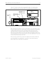
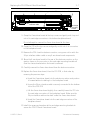
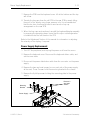
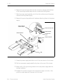
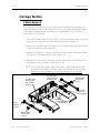
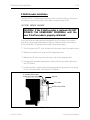
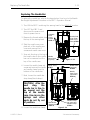
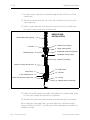
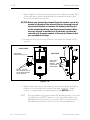
16. Connect the 26 pin interface cable connection to the bottom left of the 4
axis driver board.
17. Reconnect the Z motor harness at the top right corner of the 4 axis driver
board.
18. Reconnect the Z encoder cable at the top right corner of the CPU.
19. Reinstall the network cable, and terminator (if present) to the rear of the
peripheral at the CPU card edge mounting bracket.
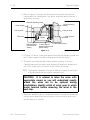
20. Reinstall the RFI shielding panel in front of the 4 axis driver board in the
electronics section.
21. Reinstall the ground cable and associated hardware at the middle front of
the RFI shielding panel.
22. Replace the electronics cover.
EMC 1 Technical Manual
Melco Embroidery Systems