1
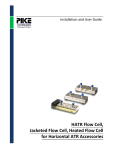
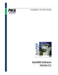
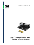
Installation and
User Guide
MIRacle ATR
TM
for FTIR Spectrometers
The information in this publication is provided for reference only. All
information contained in this publication is believed to be correct and
complete. PIKE Technologies Inc. shall not be liable for errors contained
herein nor for incidental or consequential damages in connection with the
furnishing, performance, or use of this material. All product specifications,
as well as the information contained in this publication, are subject to
change without notice.
This publication may contain or reference information and products
protected by copyrights or patents and does not convey any license
under the patent rights of PIKE Technologies, Inc. nor the rights of others.
PIKE Technologies Inc. does not assume any liability arising out of any
infringements of patents or other rights of third parties.
This document contains confidential or proprietary information of PIKE
Technologies, Inc. Neither this document nor the information herein is to
be reproduced, distributed, used or disclosed, either in whole or in part,
except as specifically authorized by PIKE Technologies, Inc.,
PIKE Technologies, Inc. makes no warranty of any kind with regard to this
material including, but not limited to, the implied warranties of
merchantability and fitness for a particular purpose.
Copyright 1991-2006 by PIKE Technologies, Inc., Madison, WI 53719.
Printed in the United States of America. All world rights reserved. No part
of this publication may be stored in a retrieval system, transmitted, or
reproduced in any way, including but not limited to, photocopy,
photograph, magnetic or other record, without the prior written permission
of PIKE Technologies, Inc.
Address Comments to:
PIKE Technologies, Inc.
2901 Commerce Park Drive
Madison, WI 53719
Phone
Fax
E-mail
Web Site
(608) 274-2721
(608) 274-0103
[email protected]
www.piketech.com
Part Number
Release
350-025004
September 2006
CONTENTS
INTRODUCTION ............................................................................................................. 4
UNPACKING YOUR ACCESSORY ............................................................................... 6
Packing List, MIRacle ATR Accessory ................................................................................................................... 6
Packing List, MIRacle Pressure Clamp, Universal Plate Options ......................................................................... 7
INSTALLATION .............................................................................................................. 8
Accessory Adjustment .............................................................................................................................................. 8
Performance Verification ........................................................................................................................................ 9
SAMPLING PROCEDURES......................................................................................... 10
Liquid Sampling Configuration ............................................................................................................................. 10
Solid Sampling Configuration ............................................................................................................................... 11
Pressure Clamp Tip Attachments .......................................................................................................................... 11
Pressure Clamp Installation and Operation .......................................................................................................... 12
Volatiles Cover ....................................................................................................................................................... 15
Configuration for Powder Sampling ...................................................................................................................... 15
Crystal Cleaning .................................................................................................................................................... 16
Effects of Temperature ........................................................................................................................................... 16
ATR SPECTRA ............................................................................................................. 16
ATR Correction ...................................................................................................................................................... 17
Liquids .................................................................................................................................................................... 18
Solids ...................................................................................................................................................................... 19
USEFUL EQUATIONS ................................................................................................. 20
Depth of Penetration ............................................................................................................................................... 20
MATERIALS .................................................................................................................. 20
Zinc Selenide .......................................................................................................................................................... 21
AMTIR .................................................................................................................................................................... 21
Germanium ............................................................................................................................................................. 21
Silicon .................................................................................................................................................................... 21
Diamond .................................................................................................................................................................. 21
PRECAUTIONS ............................................................................................................ 22
MIRRORS ..................................................................................................................... 22
SAFETY ........................................................................................................................ 22
MAINTENANCE/REPLACEMENT PARTS LIST ......................................................... 23
MIRacle Accessory User Guide
Page 3
INTRODUCTION
MIRacleTM is the PIKE Technologies patented Universal Sampling Accessory Family
designed for Single or Multi-Reflection Horizontal ATR (HATR) and Specular
Reflectance measurements with FTIR spectrometers. The accessory features a unique
optical design (US.PAT: 5,965,889 and 6,128,075), which provides exceptional
sensitivity and IR throughput. The single reflection sampling plate of the accessory has a
1.8 mm round crystal surface allowing reliable analysis of small samples. Solid materials
can be put in good physical contact with the sampling area through high pressure
clamping, yielding high quality, reproducible spectra. ATR crystal plates come in several
configurations, including ZnSe, AMTIR, Ge, Si or Diamond. The first three options are
suitable for analysis of liquids, semi-liquid materials and pliable solids. The Si or
diamond configurations should be used when working with reactive samples and/or
abrasive solid materials which need to be pressed hard against the crystal. Singlereflection ATR works very well for the analysis of relatively strong absorbing substances
(e.g. polymers, rubber, paint chips, fibers, etc.). Highly absorbing samples, such as
black rubber are best analyzed using the Ge plate due to it’s lower depth of penetration.
Acidic samples are best handled with AMTIR, Ge, Si or Diamond crystal plates. For
samples with relatively lower absorption characteristics or when trace elements are
present, the new 3 reflection plates are also available in most crystal materials. Also, the
MIRacle specular reflectance plate provides for even more flexibility for doing 45
degree specular reflectance work without the need to change the accessory base.
The compact design of the accessory employs a transfer mirror to direct the infrared
beam to one end of an IR transmitting ATR crystal (or specular reflectance reflectance
mirrors). A second mirror directs the beam emitted from the other end of the MIRacle
plate to the detector built into your FTIR spectrometer.
The MIRacle features a universal sampling plate design which eliminates the need for
separate trough and flat plates, such as normally in HATR for handling liquid and solid
samples, respectively. The accessory can be equipped with a wide choice of
compression clamps, including micrometer controlled, high pressure, rotating high
pressure, digital readout high pressure and viewer high pressure clamp. Included as
standard are the base optics assembly with baseplate and purge tubes specific to your
FTIR spectrometer model, trough plate insert, mounting ring, volatiles cover, purge
tubing attachments and adjustment wrench set. Add to this your choice of MIRacle
universal plate(s) and pressure clamp(s), all of which are easily interchangeable.
MIRacle Accessory User Guide
Page 4
Sample clamp with
micrometer controlled
spring tension
(other clamps also available)
Clamp position control knob
Mounting ring
Teflon liquid holder
Liquid plate (trough) insert
Sampling area
Universal ATR plate
Base assembly
Exploded view of the MIRacle, Single Reflection Horizontal ATR Accessory
MIRacle Accessory User Guide
Page 5
UNPACKING YOUR ACCESSORY
In order for you to quickly verify receipt of your accessory, we have included a
packing list. Please inspect the package carefully. Call PIKE immediately if any
discrepancies are found.
PACKING LIST
MIRacle ATR Accessory
MIRacle Base Optics Assembly*
Purge Tubes*, 2 each
Mounting Ring & Trough Insert*
Volatiles Cover**
Purge Tubing kit w/connector**
Alignment Wrench Set**
* The MIRacle base optics assembly has the Universal Plate, purge tubes, trough insert and mounting
ring attached to the base when purchased with a Universal ATR Plate. Some base optics assemblies
may appear different (such as adjustment screw locations and mounting scheme)
** The purge tubing kit, wrench set, volatiles cover, pressure Clamp and tips (when ordered) are
packed separately in the carrying case. The purge tubing kit is not needed with some models
equipped with recognition bases. The Swivel Tip is attached to the Sample Clamp assembly
MIRacle Accessory User Guide
Page 6
PACKING LIST (CON’T)
MIRacle Pressure Clamp Options
MIRacle Micrometer Pressure
Clamp
MIRacle High Pressure Clamp
MIRacle Rotating High Pressure
Clamp
MIRacle Digital Readout High
Pressure Clamp
MIRacle Viewer Pressure Clamp
Pressure Tips: Swivel Tip,
Concave Tip, Flat Tip;1 Each
Note: Tip of swivel tips for Micrometer clamp and 3 reflection plates are made of (white)
plastic; Swivel tip for High Pressure clamps are Stainless Steel. Depending on specific
clamp, the pressure tips may appear different than the picture.
MIRacle Universal Plate Options
Single Reflection ATR Plate
MIRacle Accessory User Guide
3 Reflection ATR Plate
(includes 5mm swivel tip)
Specular Reflection Plate
Page 7
INSTALLATION
The MIRacle accessory has been aligned and tested in the PIKE Technologies facility to
ensure that it performs to specifications. However, some variation in optical alignment
can occur from spectrometer to spectrometer. To allow for this difference, there are
four alignment screws provided on the MIRacle base optics assembly for fine-tuning,
once the accessory is installed in the spectrometer. The following is the procedure for
accessory installation and final alignment.
1.
2.
3.
The MIRacle accessory fits into the sample compartment of the FTIR
spectrometer. Your MIRacle is provided with the appropriate sample
compartment baseplate for the model FTIR instrument you specified. Before
inserting the accessory in the sample compartment, ensure that your
spectrometer is aligned. If the instrument is not aligned, maximize the
interferogram signal (the IR energy throughput) of your FTIR spectrometer.
This should be performed by following the manufacturer’s instructions. When
this has been done, collect a single beam background spectrum. In order to
locate the accessory in the correct position, simply place the entire accessory
into the FTIR sample compartment with the PIKE MIRacle label facing the
front and line up the baseplate provided with the holes/pins in your model FTIR
Spectrometer.
Fasten the accessory onto the FTIR sample compartment baseplate using the
captive screw(s) located on the MIRacle baseplate (some accessories may
have two mounting screws or a mounting screw/pin combination, depending on
spectrometer configuration).
Tighten the captive mounting screw (with flat head screwdriver or by hand) to
firmly position the accessory baseplate onto the FTIR sample compartment
baseplate. The MIRacle accessory is now ready for optical alignment.
Accessory Adjustment
The MIRacle accessory may not require any alignment when installed. However,
should you choose to fine-tune the accessory, follow these steps:
1.
Display the live interferogram on the spectrometer monitor and using the thumb
screw on the left side of the accessory, adjust the left mirror until the highest
throughput is achieved. To do this, turn the screw slightly clockwise and check
the signal. If it increases, continue until the maximum is obtained. If it decreases
turn the screw counterclockwise to get the highest possible reading.
2.
Repeat the same procedure with the right thumb screw.
3.
Insert the enclosed allen wrench in the front adjustment screw on the top of the
accessory. Adjust the screw until the highest throughput is obtained.
4.
Repeat the same alignment step with the rear screw positioned on the top plate.
5.
Repeat the entire procedure 2-3 times to fine-tune the accessory.
Note: For some side focus FTIR models, both thumb screws are located on the right side of
the MIRacle base optics assembly.
MIRacle Accessory User Guide
Page 8
This is an initial (one-time) alignment procedure which optimizes the MIRacle to
work with an individual optical bench. Once completed, the alignment does not
have to be repeated, unless the accessory adjustments have been moved or it has been
placed in a different FTIR instrument. You are now ready to verify the MIRacle optical
throughput performance.
PERFORMANCE VERIFICATION
•
With the accessory removed from the sample compartment, collect a
background spectrum (as mentioned in step 1 of the installation instruction on page 8).
•
Place the MIRacle accessory in the instrument per steps 1, 2 and 3 of the
installation instruction on page 8.
•
Collect a transmission spectrum using the same collection parameters as
used to collect the background spectrum.
The following are the % transmission values the accessory should achieve with different
crystal configurations at 1000 cm-1 (with the exception of the Si value which is shown at
2000 cm-1 ).
ZnSe single reflection ATR plate:
AMTIR single reflection ATR plate:
Ge single reflection ATR plate:
Diamond w/ZnSe lens single reflection ATR plate:
Diamond w/KRS-5 lens single reflection ATR plate:
Si w/ZnSe lens single reflection ATR plate:
ZnSe 3 reflection ATR plate:
AMTIR 3 reflection ATR plate:
Diamond w/ZnSe lens 3 reflection ATR plate:
Specular Reflectance plate:
Greater than 22%T
Greater than 22%T
Greater than 25%T
Greater than 25%T
Greater than 22%T
Greater than 22%T
Greater than 12%T
Greater than 12%T
Greater than 12%T
Greater than 20%T
If your accessory does not meet this minimum transmission level, please contact PIKE
Technologies. Before making this call, please record the serial number located on the
label on the back of the MIRacle base optics assembly.
Note: IR throughput performance of your accessory will decrease slowly over time as
the lens surface is exposed to the environment and due to normal wear from cleaning the
ATR surface. Contact PIKE Technologies for information about MIRacle Universal
Plate refurbishment services when transmission throughput drops below a usable level.
MIRacle Accessory User Guide
Page 9
SAMPLING PROCEDURES
The spectrum of the required sample is obtained by ratioing a scan with a sample
in place to a scan with no sample on the face of the crystal. The crystal mount is
located on the base unit. A single crystal design is used for all types of samples
(liquids, pastes, soft pliable films and solids).
Configuration for Liquid Sampling
Note: The MIRacle accessory is typically shipped in a liquid sampling configuration with trough
insert installed. Remove the mounting ring and trough insert plate before running solid samples.
The crystal plate assembly of the MIRacle single reflection ATR features a round plate
design, with a 1.8 mm sampling area, located in the center (6.0 mm for 3 reflection
plates). The side of the crystal plate features coarse threads provided for mounting
various attachments. For liquid sampling, a trough insert is placed on the top of the
plate and fastened with the knurled mounting ring. The insert forms a shallow well
around the crystal for containment of liquid and finely powdered samples.
The sample must be in intimate contact with the sampling area for the ATR evanescent
wave to provide the highest signal. For routine sampling, place a drop of your sample in
the trough insert and collect data. Care is required when removing the sample from the
trough. It is desired that the sample be removed without scratching the surface of the
crystal. Note that some crystals used in the accessory are made of fairly brittle
materials (such as ZnSe, Si, Ge or AMTIR). Scratches on the surface of the crystal will
result in a reduction in the throughput of the accessory. Remove the sample gently with
a non-abrasive cotton tissue and rinse with solvent. For more thorough cleaning,
unscrew the mounting ring and remove the insert. Both, the insert and the crystal plate
should be cleaned with an appropriate mild solvent, such as Isopropyl alcohol or a
stronger solvent, such as Acetone. Cotton swabs are highly recommended for ease of
cleaning without scratching the soft ATR surface.
Sometimes “carry over” may occur from one sample to another due to incomplete
cleaning of a prior sample from the face of the crystal. This effect may be minimized by
washing the trough with the new sample, cleaning the crystal and then running a
background scan. The sample is then placed on the crystal again and a sample spectrum
collected.
Samples should not be left in contact with the crystal for an extended period of time
since some samples may degrade the crystal material and discoloration of the metal
plate can occur. Once the measurement has been made, remove the sample from the
crystal and clean the surface of the crystal and the surrounding plate area with a suitable
solvent. Note that the PIKE high pressure clamps have the ability to swing sideways
for ease of accessing the crystal surface for cleaning. Also, the rotating high pressure
clamp has the ability to rotate the pressure tip to face upwards for ease of cleaning the
tip between samples.
MIRacle Accessory User Guide
Page 10
Configuration for Solid Sampling
For measurements of soft pliable films and selected solid samples, the mounting ring and
liquid trough insert should be removed from the crystal plate assembly. The sample is
placed onto the surface of the crystal. Since the ATR effect only takes place very close
to the surface of the crystal, an intimate contact has to be made by the sample on the
ATR crystal surface. This is achieved by using the pressure clamp(s) ordered with your
MIRacle system. Mount the pressure clamp to the back side of the accessory using the
two alignment dowel pins on top of the MIRacle base and fasten using the two captive
thumbscrews on the clamp frame. With the sample in place on the crystal, lower the
pressure tip so that it is in contact with the sample. With the micrometer clamp or digital
readout high pressure clamp, it is possible to achieve reproducible sampling by applying
the same amount of pressure to your samples. This is done by using the same settings
on the micrometer screw or by using the electronic digital display, respectively.
However, in most cases, it is recommended to apply the maximum pressure allowed to
ensure the best contact and highest sampling sensitivity. The maximum force applied by
the micrometer pressure clamp is 10 pounds (>2500 psi). The maximum force applied
by the high pressure clamps is 40 pounds (>10,000 psi). The high pressure clamps
have the additional advantage of a slip clutch mechanism to avoid over tightening.
Caution: Care must be used in operating the pressure clamps, since the pressure
device may slide the sample over the crystal. If the sample contains grit or abrasive
materials, the surface of the crystal may be damaged by the sample motion while
pressure is being applied. Ensure that the sample remains stationary while applying load
to the clamp. In addition, softer ATR materials, such as ZnSe, need to be handled with
care when running hard or sharp sample types. Do not apply the maximum pressure to
these types of samples on softer ATR plates to avoid cracking, denting or scratching.
Pressure Clamp Tip Attachments
The success of an ATR measurement depends mostly on the quality of the contact
between the sample and the crystal. Since there is an infinite number of sample shapes
and types, a single configuration of the sample press tip may not be adaquate. For this
reason, the MIRacle pressure clamps are designed to accept three different tip
attachments, providing the best possible configuration for any given sample type. In
addition, the 3 reflection ATR plates are provided with a special plastic swivel tip
matching it’s 6 mm diameter crystal size.
The accessory is shipped with the swivel tip attached to the pressure clamp ordered
with the MIRacle accessory. This tip features an end cap mounted onto a small ball
joint. Such design allows the pressure tip to move and adjust its position to the shape of
the sample and maintain the sample position parallel to the crystal surface. This tip
allows for better positioning and optimal contact of thin materials with the crystal
MIRacle Accessory User Guide
Page 11
surface. The swivel tip is used with irregularly shaped samples, films, semi-rigid
polymers (e.g. credit card like materials). It can also be used for special applications,
including analysis of single fibers and combinatorial chemistry beads. When using a
plastic pressure tip, it is important to prevent its direct placement on the crystal, as its
spectrum would interfere with that of the sample. This is not a problem when dealing
with a majority of samples. For small samples that do not cover the crystal when
pressed by the tip, such as beads, powders or fibers, a small piece of aluminum foil
should be placed between the tip and the sample to eliminate such exposure.
The flat tip attachment is a straight metal barrel and it is used when analyzing rubber
samples and other elastic polymers. This tip should not be used for analysis of thin films
or fibers, as it may not position the sample perfectly on the crystal surface (the swivel tip
described above is designed to perform such a function). Please keep in mind that the
depth of penetration of an ATR crystal is only in the range of 0.5 to 2 micrometers and
even a small departure from intimate contact with the crystal will affect the magnitude of
the sample absorption.
The concave tip was developed specifically to work with granules, large beads and
polymer pellets. The tip features a concaved surface which does not allow the sample to
escape from underneath the press. It also forces the sample to stay in the center of the
crystal, assuring the best possible contact.
PRESSURE TIPS:
swivel tip
flat tip
concave tip
Micrometer Pressure Clamp
The micrometer clamp assembly consists of the base which attaches directly to the
accessory top plate and the “r” shaped arm with control knobs for raising and lowering
the sample press. The clamp itself, is a stainless steel barrel with the integrated
micrometer screw at the top and the spring-loaded plunger at the bottom. A spring is
located between the shaft of the micrometer screw and the plunger. The spring tension
can be adjusted by changing the position of the micrometer screw. This adjustment
allows application of higher or lower pressure to the sample placed on the accessory’s
sampling plate.
MIRacle Accessory User Guide
Page 12
The numbers on the scale of the micrometer screw serve as reference (they do not
indicate the actual pressure applied to the sample)*. The actual pressure per square
inch (PSI) depends on the size of the tip attached to the press and the spring tension.
Listed below are the approximate pressures calculated for the square edge stainless
steel tip (diameter 0.125”).
Micrometer
Setting
3.0
2.0
1.0
0.0
Pressure
(psi)
408
530
693
815
The lighter pressures should be used for soft, flexible samples. The higher pressures are
necessary for hard polymers, bids, granules, etc. (Please see also the note on selection
of pressure clamp tips). The following is a short procedure outlining proper use of the
MIRacle micrometer controlled sample clamp (025-3050):
1.
2.
3.
4.
5.
Select the appropriate tip and attach it to the press.
Position the sample on the accessory plate.
Set the micrometer screw to 2.0.
Lower the press barrel with the control knobs, until the edge of the sampling tip
touches the lower brass end of the barrel.
Collect the sample spectrum.
Some FTIR spectrometers offer “real-time” data collection modes (names like
MONITOR, DATA PREVIEW, EXPERIMENT SETUP, etc. are used for their
description). If available, you can experimentally determine the best pressure for your
particular sample by observing the shape of the spectrum while adjusting the micrometer
screw.
* Please note that the spring in the clamp assembly is not compressed until the
micrometer screw is set to 3.5. For this reason, always keep the micrometer setting
between 3.5 and 0.
High Pressure Clamps
The high pressure clamps consist of the base which attaches directly to the accessory’s
top plate, the stainless steel pressure tip arm and the pressure control knob with built in
slip-clutch mechanism. A removable anvil is located underneath the pressure module.
This anvil is positioned in the center of the crystal plate and provides direct pressure to
the sample. The pressure clamp module rides up and down on a lead screw located in
the clamp column, with its position adjusted by the control knob. The control knob
features a rachet-type clutch mechanism that controls the maximum allowable pressure
and protects the crystal from over tightening. PIKE offer 4 versions of this style clamp.
MIRacle Accessory User Guide
Page 13
High Pressure Clamp Installation
1. Position the clamp on the two dowel pins located on the top plate of the MIRacle accessory.
Please note that the top plate extends approximately 1/4” beyond the MIRacle base. The clamp
mount provides a space to accommodate for this extension. Before the clamp can be fully mounted
on the pins, the plate extension and the groove in the clamp mount must be perfectly aligned.
2. Press the clamp down until the pins fully engage. Using a flat head screwdriver, tighten the captive
screws so the clamp is firmly attached to the accessory base.
3. For Digital readout clamp only: Flip the switch on the top of the clamp to “ON” position. The digital
display located on the beveled surface of the pressure module should display “000”. The numbers
displayed on the digital readout should be treated as arbitrary unit reference points, as they do not
indicate the actual pressure applied to the sample. The actual pressure per square inch (PSI)
depends on the size of the tip attached to the press. The direct pressure applied at the maximum
compression point is approximately 40 pounds. The lighter pressures should be used for soft, flexible
samples. The higher pressures are necessary for hard polymers, beads, granules, etc.
4. As with the micrometer pressure clamp, the high pressure clamps are provided with three pressure
tips; swivel, flat and concave. However, the swivel tip for the high pressure clamps is made of metal
vs. white plastic due to the higher clamping forces involved.
5. The clamp is now ready for use.
The diagram below shows how the high pressure clamp models are able to swing to the side for
ease of cleaning. It also identifies the slip clutch knob used for applying pressure to the sample
without over tightening. A detent holds the pressure clamp tip in place directly over the crystal.
Pressure Control Knob
Display Battery Location
Display On/Off Switch
Digital Readout Pressure Display
Digital, High Pressure Clamp rotated for
easy access to the crystal plate
MIRacle Accessory User Guide
Page 14
Viewer Clamp Installation
The MIRacle Viewer operates with the standard high
pressure clamp assembly. The Viewer helps position
small samples centered on the small ATR crystal. To
operate, place the sample on the crystal surface and
lower the clamp using the control knob until the
sapphire window makes contact with the sample. To
make small adjustments to the sample position,
loosen the control knob slightly, re-position the
sample and re-tighten the control knob. For best
viewing of the sample area, look through the lens on
the top of the Viewer positioning your eye 2-10
inches away. The sample area is illuminated through
the lens by ambient light, so do not block the natural
room light from the Viewer eye piece. The sharpest
image can be obtained when the sample is in contact
with the window.
Sample Analysis with High Pressure Clamps
1. Select the appropriate pressure tip and attach it to the clamp’s pressure tip arm (see tip descriptions
and their recommended use on page 11 and 12).
2. Position the sample on the accessory sampling plate.
3. Lower the pressure module with the control knob(turning clockwise) until the desired pressure is
achieved.
5. Collect the sample spectrum.
Caution : MIRacle ATR universal plates damaged by excessive pressure cannot be covered by the
warranty. Extreme caution is required when using the high pressure clamps with ZnSe, Ge, AMTIR and
Si crystal ATR universal plates. In addition, the diamond component utilized in this accessory is only 0.5
mm thick. This crystal will withstand higher pressures than traditional IR materials, but it still may be
damaged by an excessive force. For this reason, do not exceed the pressure originally set by the
factory on the high pressure clamps. In addition, maximum pressure (10,000 psi) should only be used
when the sample makes contact with the entire 1.8mm dia. surface area of the ATR.
Volatiles Cover
A cover is provided to place over the sample when volatile liquids are being analyzed.
This reduces the amount of evaporation of the sample on the surface of the crystal.
Configuration for Powder Sampling
With care, most powders may be analyzed with an ATR accessory. Note that since the
ATR effect requires the sample to be in intimate contact with the crystal, this method is
most effective when analyzing soft powders. Configure the MIRacle accessory for liquid
sampling by installing the trough insert, holding it down with the knurled mounting ring.
MIRacle Accessory User Guide
Page 15
Mount the clamp using the two captive thumbscrews. Powders may now be placed in
the trough and pressed into contact using the press. Note that hard/abrasive powders
should be analyzed only with diamond ATR to avoid scratches/damage to the surface of
softer crystal materials. Often, the trough insert and mounting ring are not required. In
some cases, diffuse reflectance is the preferred technique for powder analysis.
Crystal Cleaning
The solvent used for cleaning your crystal is dependent on the sample that has been
analyzed. In all cases it is best to attempt to clean the crystal with the mildest solvent
possible. For most cases, the preferred solvent is isopropyl alcohol. If a stronger
solvent is required, acetone may be used. In very stubborn cases dimethylformamide
may be used. In all cases when using solvents, inspect the materials safety data sheet
associated with the solvent you are using and comply with any recommended handling
procedures. Apply the solvent to the crystal with a Q-tip and gently remove using a
Q-tip or non-abrasive wipe. Repeat this procedure until all traces of the sample have
been removed. Under no circumstances should the softer crystal materials (ZnSe,
AMTIR, Ge) be rubbed with paper products such as “Kleenex” or “Kimwipes”. Many
paper products are abrasive and could cause scratching of the softer crystal surfaces.
Effects of Temperature
The PIKE Technologies MIRacle utilizes an indium gasket to seal the crystal to its
mount. This sealing mechanism allows some flexibility and hot samples may be placed
on the crystal without damaging the crystal or seal. However, it is recommended that
the temperature difference between the sample and the crystal be not more that 30
degree Celsius. So for a crystal at room temperature, the sample may be at a
temperature of up to 50 degrees Celsius. Please contact PIKE Technologies if you
wish to place samples of a higher temperature on the crystal surface. Heated MIRacle
plates are also available and can be heated up to 120C (60C for Diamond).
ATR SPECTRA
ATR spectra are similar to transmission spectra. A careful comparison of ATR spectra
and transmission spectra reveals that the intensities of the spectral features in an ATR
spectrum are of lower absorbance than the corresponding features in a transmission
spectrum and especially in the high wavenumber (short wavelength) region of the
spectrum. The intensity of the ATR spectrum is related to the penetration depth of the
evanescent wave into the sample. This depth is dependent on the refractive index of the
crystal and the sample, and upon the wavelength of the IR radiation.
The relatively thin depth of penetration of the IR beam into the sample creates the main
benefit of ATR sampling. This is in contrast to traditional FT-IR sampling by
transmission where the sample must be diluted with IR transparent salt, pressed into a
pellet or pressed to a thin film, prior to analysis to prevent totally absorbing IR bands.
MIRacle Accessory User Guide
Page 16
A comparison of transmission vs. ATR sampling result for a thick polymer sample is
shown below where the sample is too thick for high quality transmission analysis (shown
in the lower spectrum). In transmission spectroscopy, the IR beam passes through the
sample and the effective path length is determined by the thickness of the sample and its
orientation to the directional plane of the IR beam. Clearly in the example below the
sample is too thick for transmission analysis because most of the IR bands are totally
absorbing.
However, simply placing the thick sample on the ATR crystal (Diamond MIRacle) and
applying pressure generates a high quality spectral result (upper red spectrum) identified by library search as a polybutylene terephthalate. The total analysis time for
the thick polymer by ATR was less than 1 minute.
ATR Correction
If an ATR spectrum representative of a transmission spectrum is desired, the ATR
spectrum must be processed with the ATR correction program available on your
instrument. An example of the effect of this correction on a spectrum is shown in the
following example for polystyrene. The lower spectrum is the original ATR spectrum of
polystyrene. The middle, blue spectrum is the transmission spectrum of polystyrene.
Clearly the IR bands around 3000 cm-1 in the ATR spectrum are weaker relative to the
IR bands at longer wavelength.
However, in the upper red spectrum after ATR correction, we see relative IR band
intensities very similar to those from the polystyrene run by transmission.
MIRacle Accessory User Guide
Page 17
Liquids
Two, one minute, 4 cm-1 resolution spectra of dishwashing liquids were collected using a
trough plate configuration. There is an apparent difference between the purely water
based and alcohol containing detergents.
100
Transmittance
90
80
70
60
1800
1600
1400
1200
Wavenumber (cm-1)
1000
800
600
Comparison of liquid detergents
Two, one minute, 4 cm-1 spectra were collected using a trough plate crystal. The
samples were a diet and regular soft drink.
.12
.1
Absorbance
.08
.06
.04
.02
0
1800
1600
1400
Wavenumber (cm-1)
1200
1000
Comparison of two soft drinks
MIRacle Accessory User Guide
Page 18
Solids
The spectrum below is of a plastic bottle. A section was cut out of the bottle and
analyzed using the MIRacle in a flat plate configuration. The sample was kept in contact
with the ATR crystal using the micrometer pressure clamp. The acquisition time was
one minute at a resolution of four wavenumbers.
.8
.7
.6
Absorbance
.5
.4
.3
.2
.1
0
3500
3000
2500
2000
Wavenumber (cm-1)
1500
1000
Spectrum of plastic bottle
The following are two overlaid spectra showing each side of a multilayer plastic food
wrapping material. The sample was kept in contact with the ATR crystal using the
clamp. The acquisition time was one minute at a resolution of four wavenumbers.
.25
Absorbance
.2
.15
.1
.05
0
3500
3000
2500
2000
Wavenumber (cm-1)
1500
1000
Spectra of food wrapping material
MIRacle Accessory User Guide
Page 19
USEFUL EQUATIONS
The depth of penetration gives us a relative measure of the intensity of the resulting
spectrum and is expressed by the following equation:
λ
dp =
(
2π n12 sin 2 θ1 − n22
)
1
2
where:
λ
n1
n2
= Wavelength of light
= Angle of incidence of the IR beam
= Refractive index of the crystal
= Refractive index of the sample
Below is a table giving depth of penetration in microns as a function of crystal material.
The penetration depth is calculated for a sample with a refractive index of 1.5 at 1000
cm-1 . Also the safe pH range of samples for use with each material is listed.
Material
ZnSe
AMTIR
Ge
Si
Diamond
Refr. Index
2.4
2.5
4
3.4
2.4
45 degrees
2.0
1.7 θ
0.66
0.85
2.0
Safe pH range
5-9
1-9
1 - 14
1 - 12
5-8
MATERIALS
The following ATR crystal materials are available:
Material
ZnSe
AMTIR
Ge
Si
Diamond/ZnSe
Diamond/KRS-5
Refractive Index
at 1000 cm-1
2.4
2.5
4
3.4
2.4
2.4
Spectral Range
(cm-1)
15,000 - 630
11,000 - 630
5,500 - 780
8,300 - 1,500
17,900 - 525
17,900 - 250
Note: Quoted spectral range also depends upon the FTIR Spectrometer Configuration
of source, beamsplitter and detector and other components.
MIRacle Accessory User Guide
Page 20
Zinc Selenide
ZnSe is the preferred replacement for KRS-5 for all routine applications. Its useful
spectral range is less at the low frequency end than that of KRS-5, but the mechanical
strength of this rigid, hard polycrystalline material is superior. Although a general
purpose material, it has limited use with strong acids and alkalies. The surface becomes
etched during prolonged exposure to extremes of pH. Note that complexing agents,
such as ammonia and EDTA, will also erode its surface because of the formation of
complexes with the zinc.
AMTIR
This material produced as a glass from selenium, germanium and arsenic, AMTIR is
considered to be highly toxic during the manufacturing process. However, the brittle
nature of the material and its total insolubility in water makes it safe for use as an internal
reflectance element. It has a similar refractive index to zinc selenide and can be used in
measurements that involve strong acids.
Germanium
Germanium has been used extensively in the past as a higher refractive index material for
samples that produce strong absorptions such as rubber O-rings. The crystal is also
used when analyzing samples that have a high refractive index, such as in passivation
studies on silicon.
Silicon
Silicon is hard and brittle. It is chemically inert and it is affected only by strong
oxidizers. Silicon is well suited for applications requiring temperature changes as it
withstands thermal shocks better then other ATR materials. It also is the hardest crystal
material offered except for Diamond, which makes it well suited for abrasive samples
that might otherwise scratch softer crystal materials. Typically, Silicon crystal is totally
absorbing below 1500 cm-1 making its usefulness in the mid-IR range limited. However,
the Si Universal Plate for the MIRacle is a special composite design using a ZnSe
focusing lens that reduces the pathlength of light through the Silicon significantly. This
results in a much broader available spectral range.
Diamond
Diamond is one of the most rugged optical materials. It can be used for analysis of a
wide range of samples, including acids, bases, and oxidizing agents. Diamond is also
scratch and abrasion resistant. Its disadvantage is the cost and the intrinsic absorption
from approximately 2300 to 1800 cm-1 which limits its usefulness in this region (5%
transmission).
MIRacle Accessory User Guide
Page 21
PRECAUTIONS
Mirrors
In order to provide the maximum transmission in the infrared, with the minimum spectral
interferences, the mirrors used in this device are uncoated (bare) aluminum on a glass
substrate. Since the coatings are soft, care must be taken to avoid damage. Normally,
these mirrors will not need cleaning, since they are contained within the housing of the
accessory. If they do need cleaning, they may be gently wiped with a lint free, abrasive
free cloth, such as lens tissue, or with a camel hair brush. Under no circumstances must
the mirrors be rubbed with paper products such as “Kleenex” since this will produce
scratching of the mirror surface.
Safety
Caution should be used when handling and using ATR crystals since some of the
materials can be hazardous. Specifically, zinc selenide is a heavy metal material and
should be handled with this in mind. If the crystal is broken or pulverized, the dust may
be harmful by inhalation, ingestion or skin absorption.
MIRacle Accessory User Guide
Page 22
MAINTENANCE/REPLACEMENT PARTS LIST
The following maintenance and replacement parts are available:
Crystal Plates
025-2010
025-2050
025-2070
025-2090
025-2096
025-2100
025-2110
025-2030
025-2200
Single Reflection ATR Universal Plate, ZnSe Crystal
Single Reflection ATR Universal Plate, Ge Crystal
Single Reflection ATR Universal Plate, AMTIR Crystal
Single Reflection ATR Universal Plate, Si w/ZnSe lens
Single Reflection ATR Universal Plate, Si Crystal
Single Reflection ATR Universal Plate, Diamond
3 Reflection ATR Universal Plate, Diamond
3 Reflection ATR Universal Plate, ZnSe
Specular Reflectance Universal Plate
Heated Crystal Plates
025-4010
025-4050
025-4070
025-4090
025-4100
Heated Single Reflection ATR Universal Plate, ZnSe Crystal
Heated Single Reflection ATR Universal Plate, Ge Crystal
Heated Single Reflection ATR Universal Plate, AMTIR Crystal
Heated Single Reflection ATR Universal Plate, Si Crystal
Heated Single Reflection ATR Universal Plate, Diamond
(Note: Diamond has limited range to 60C)
025-3020
025-3035
025-3050
025-3075
025-3090
025-3300
025-3310
MIRacle High Pressure Clamp
MIRacle Confined Space High Pressure Clamp
Micrometer Controlled Sample Clamp
Rotating tip High Pressure Clamp
Digital Readout High Pressure Clamp
MIRacle Viewer Pressure Clamp
Viewer for MIRacle High Pressure Clamp
025-3051
025-3053
025-3099
025-3056
025-3057
025-3060
025-3091
025-5010
025-5012
Volatiles Cover
Micrometer Controlled Press Tips Assortment
High Pressure Clamp Tip Assortment
Replacement Trough Teflon Inserts (2)
MIRacle Mounting Ring
MIRacle Combinatorial Chemistry Kit
Battery Pack, Digital High Pressure Clamp
MIRacle Liquid Jacketed Module
MIRacle Flow-through Attachment
Pressure Clamps
Other
MIRacle Accessory User Guide
Page 23