1
TC8520
4 CHANNEL TELEPHONE,
1 CHANNEL 10/100 BASE-T &
(Optional 4 Channels Data)
FIBER OPTIC MULTIPLEXER
User's Manual
MODEL:
S/N:
DATE:
Notice!
Although every effort has been made to insure that this manual is current
and accurate as of date of publication, no guarantee is given or implied
that this document is error free or accurate with regard to any specification. TC Communications, Inc. reserves the right to change or modify
the contents of this manual at any time without prior notification.
© COPYRIGHT 1992-2005. ALL RIGHTS RESERVED.
Table Of Contents
TC8520 User's Manual
Rev. 1.8
Chapter 1 - Overview ............................................................................................................... 4
Features ......................................................................................................................................... 4
Description ..................................................................................................................................... 4
Typical Application Using the TC8520's ...................................................................................... 5
TC8520 Pizza Box Rackmount Unit ............................................................................................. 5
Optical Specifications ................................................................................................................... 6
Theory of Operation ...................................................................................................................... 8
LEDs, DIP Switches and Connectors .......................................................................................... 9
Optic Board (lower board) LED and DIP Switch Functions .................................................... 11
Ethernet, Data, Alarm, and Optical Status LEDs ................................................................ 11
Data, Optical and Power Status LEDs ................................................................................. 12
DIP Switch Functions ........................................................................................................... 12
Interface (Telephone) Board LEDs and Functions.................................................................. 13
Data Signal Status LED Indicators ...................................................................................... 13
Telephone Signal Status LEDs ............................................................................................ 13
Power Status LEDs ............................................................................................................... 14
FXS and FXO Card's DIP Switch Functions ........................................................................ 14
Base (Optical) Card Internal DIP Switch (SW2) ...................................................................... 15
Extension (Telephone) Card Internal DIP Switch (SW2) ........................................................ 15
Optical Redundancy (Optional) ................................................................................................. 16
Two-way "Single Fiber" (Optional) ............................................................................................. 16
Chapter 2 - Installation ......................................................................................................... 17
Unpacking the Unit .....................................................................................................................
Equipment Location ...................................................................................................................
Dry Contact Alarm Relay ............................................................................................................
Power Supply ..............................................................................................................................
Telephone Signal Connection ...................................................................................................
Ethernet 10/100Base-T Signal & Electrical Signal Interface Connections ...........................
System Start Up..........................................................................................................................
Interface Board .....................................................................................................................
Optical Board ........................................................................................................................
Installation Procedure Summary ..............................................................................................
Standard Applications to Extend Analog Telephone Lines.....................................................
Phone Line Extension ..........................................................................................................
Hotlink Phone Extension .....................................................................................................
17
17
17
17
17
17
18
18
18
18
19
19
19
Chapter 3 - Troubleshooting ................................................................................................ 20
General ........................................................................................................................................
All LEDs are Off ..........................................................................................................................
"ALM" LEDs on the Optical Board .............................................................................................
Optic Cable Types ......................................................................................................................
Calculating the Loss on the Fiber .............................................................................................
20
20
20
20
20
Chapter 4 - Bench Tests ....................................................................................................... 21
Ethernet/Web Page Test ............................................................................................................
Conducting a Signal Generator Test (On Units with Data Only) ............................................
Ring Test (FXS unit only) ...........................................................................................................
Local Electrical Loopback Test on the TC8520s (On Units with Data Only) .........................
Local Optical Loopback Test on the TC8520 (On Units with Data Only) ...............................
-2-
21
21
22
22
22
TC8520 User's Manual
Rev. 1.8
Chapter 5 - Electrical Interfaces & Pin Assignments ......................................................... 23
Optical Card RJ-45 Pin assignments ........................................................................................
RS-232 Async and Sync Connections ................................................................................
RS-422 (Async) Connection ................................................................................................
Dry Contact Closure Detector & Relay Switch ..................................................................
Phone Card RJ-11 Pin assignments .........................................................................................
Telephone Connection .........................................................................................................
Four Wire Analog Connection .............................................................................................
Two Wire Analog Connection ...............................................................................................
23
23
24
24
25
25
25
25
Chapter 6 - Software Configuration ..................................................................................... 26
Configure your TC8520 .............................................................................................................
Data/Voice Status .......................................................................................................................
Ethernet History Statistics ........................................................................................................
Ethernet Event Statistics ...........................................................................................................
Configure Basic Switch Settings ..............................................................................................
Configure Network/IP Settings .................................................................................................
TC8520 Slave Configuration .....................................................................................................
Configure Ethernet Settings .....................................................................................................
Rate Limit Settings .....................................................................................................................
Rx(Ingress) Limit ..................................................................................................................
Tx (Egress) Limit ..................................................................................................................
Summary Page ............................................................................................................................
Link Status for Primary and Secondary Optical Links ............................................................
Configure Login Settings and Levels of Privilege ..................................................................
Levels of Privilege ................................................................................................................
Console Settings (On Units with Data Only) ...........................................................................
Console Help ..............................................................................................................................
"Show" Command .......................................................................................................................
Telnet Settings ............................................................................................................................
26
27
28
29
30
31
31
36
37
37
37
38
38
39
40
42
43
44
45
Chapter 7 - PC IP Configuration .......................................................................................... 46
Chapter 8 - Specifications .................................................................................................... 47
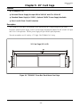
Chapter 9 - 19" Card Cage .................................................................................................. 48
Features ...................................................................................................................................... 48
Description .................................................................................................................................. 48
Chapter 10 - Return Policy and Warranty ........................................................................... 49
Return Policy .............................................................................................................................. 49
Warranty ...................................................................................................................................... 49
-3-
Chapter 1 - Overview
TC8520 User's Manual
Rev. 1.8
Features
p Multiplexes 10/100 Ethernet, 2-Wire Analog POTs or 2/4-Wire 600 Ohm Analog and
Optional RS-232, RS-422, TTL, or Dry Contact
p 10/100 Auto-Negotiating and Bandwidth Control on the Ethernet Bridging Port
(32Kbps increments up to 10Mbps)
p 1 to 4 Channels of Telephone or combo, Replaceable Line Interface Module
p Web-Based & Telnet Configuration (Serial Configuration Only for Units Without Data)
p Hardened Temperature (optional), -40oC to 80oC Exceeds NEMA & CALTRANS Specs
p Optional Optical Redundancy
p Distances up to 100km, Multimode (1310nm) or Single Mode (1310nm/1550nm)
p Two-way "One Fiber" Communication (optional)
p Built-In Power Redundancy, Optional 24VDC, or 115/230VAC Power
p Local Dry Contact Alarm Relay
p Rackmount or Standalone
Description
The TC8520 Telephone, Ethernet & Data Fiber Multiplexer multiplexes various combinations of 2-wire
Analog POTS or 2/4-wire 600 Ohm Analog, 1 Ch. 10/100 Ethernet and optional Serial Data channels over
single mode or multimode fiber.
The TC8520 supports distances to more than 100 km and offers a two-way, “one fiber” communication option
to maximize fiber cable usage. Optional redundant power and optics include automatic switchover for
maximum reliability.
Setup, diagnostics and control is accessed via Serial Terminal, Telnet management ports. Diagnostics include
LED indicators, dry contact alarms and local and remote loopback.
The Ethernet port auto-negotiates at 10/100 with full 10Mbps throughput and rate control in increments of
32Kbps. It is IEEE 802.3/802.3u/802.3x compliant.
The TC8520 converts 2-wire FXS to fiber optics on the telephone side with ring down capability and FXO
on the PBX side. Because the TC8520 digitizes the analog signals (PCM), voice quality does not degrade
over extended distances. Serial interface options are RS-232, RS-422, TTL, Dry Contact.
The TC8520 is available in basic standalone unit or optional, 1U high rackmount card "pizza box." The
rackmount card fits into a 19" Rackmount Card Cage. Fiber optic connectors are ST, FC or SC. Standard
power is 12VDC and includes built-in redundancy. Optional power sources include 24VDC or 115/230VAC
with an external power cube. High temperature (-20°C to 70°C) and extreme temperature (-40°C to 80°C)
versions are also available.
-4-
TC8520 User's Manual
Rev. 1.8
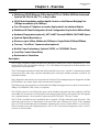
Typical Application Using the TC8520's
Typical applications include extending multiple Telephone lines, Analog, Data and Ethernet channels to
remote site such as campus networks, substations, etc. The two-way “one fiber,” option can double usage
of existing fiber optic cable plants.
Figure 1. Typical Application Using the Standalone TC8520 Fiber Optic Multiplexers
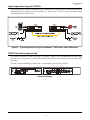
TC8520 Pizza Box Rackmount Unit
The optional variation is so called "pizza box" (TCRM195) which is a 19" rackmountable with one U high
horizontal box. The pizza box version of TC8520 has the same PC cards installed except the sheet metal
packaging.
The DIP switches and LEDs are all the same as stand-alone version of the TC8510.
Pizza Box Version
-5-
TC8520 User's Manual
Rev. 1.8
Optical Specifications
Multimode Model
Transmitter:
LED; typical Launch Power:
-17.0 dBm* (1310nm, @62.5/125µm)
Receiver:
PIN Diode; typical Sensitivity:
Optic saturation level:
-33.0 dBm* (1310nm, @62.5/125µm)
-11.0 dBm*(1310nm, @62.5/125µm
Loss Budget:
1310nm Multimode @62.5/125µm:
15 dB
Distance:
1310nm Multimode, @62.5/125µm:
up to 4km distance*
Wavelength:
1310nm Multimode:
Connector:
ST
SC
Single Mode 1310nm, 20km Model
Transmitter:
FP Laser; typical Launch Power:
-14 to -7 dBm* (1310nm, @9/125µm)
Receiver:
PIN Diode; typical Sensitivity:
Optic saturation level:
-34.0 dBm* (1310nm, @9/125µm)
-3 dBm*(1310nm, @9/125µm)
Loss Budget:
1310nm Single Mode, @9/125µm:
20 dB
Distance:
1310nm Single Mode, @9/125µm:
up to 20 km distance
Wavelength:
1310nm Single Mode(LASER):
Connector:
ST
FC
SC
Single Mode 1310nm, 75km Model
Transmitter:
FP Laser; typical Launch Power:
-3 to 0dBm* (1310nm, @9/125µm)
Receiver:
PIN Diode; typical Sensitivity:
Optic saturation level:
-36.0 dBm* (1310nm, @9/125µm)
-3 dBm* (1310nm, @9/125µm)
Loss Budget:
1310nm Single Mode, @9/125µm:
33dB
Distance:
1310nm Single Mode, @9/125µm:
up to 75km distance
Wavelength:
1310nm Single Mode (LASER)
Connector:
ST
FC
SC
Single Mode 1550nm, 75km Model
Transmitter:
DFB Laser; typical Launch Power:
-10 to -1dBm* (1550nm, @9/125µm)
Receiver:
PIN Diode; typical Sensitivity:
Optic saturation level:
-34.0 dBm* (1550nm, @9/125µm)
0 dBm* (1550nm, @9/125µm)
Loss Budget:
1550nm Single Mode, @9/125µm:
24dB
Distance:
1550nm Single Mode, @9/125µm:
up to 75km distance
Wavelength:
1550nm Single Mode (LASER)
Connector:
ST
FC
SC
-6-
TC8520 User's Manual
Rev. 1.8
Single Fiber, 50km Model
Transmitter:
Typical Launch Power:
-8 to -3 dBm* (1310nm/1550nm, @9/125µm)
Receiver:
PIN Diode; typical Sensitivity:
Optic saturation level:
-33.0 dBm* (1310nm/1550nm, @9/125µm)
-3 dBm*
Loss Budget:
1310nm/1550nm Single Mode, @9/125µm: 29 dB
Distance:
1310nm/1550nm Single Mode, @9/125µm: up to 50km distance
Wavelength:
1310nm/1550nm Single Mode:
Connector:
SC
Only
*Launch power, sensitivity and distance are listed for reference only. These numbers may vary.
-7-
TC8520 User's Manual
Rev. 1.8
Theory of Operation
The TC8520 is designed to provide users with maximum flexibility, ease of use, simplicity and functionality.
The unit consists of two printed circuit boards (PCBs): one for telephone multiplexing and a second for 10/
100Base-T Ethernet signal and Data. The Telephone interface PCB (board with no optics) provides for the
telephone lines.
The optical PCB (board with optics) provides for the one channel 10/100Base-T Ethernet and up to four
optional channels of data, optic transmitter/receiver operations and data serialization. It converts electrical
signals to optic signals and converts the parallel data bits to serial format for data transmission across the
fiber link. The reverse process occurs at the opposite end, where the serial data is converted into parallel
format for the electrical signals, which is then transmitted to another device.
Any loss of optical signal on the primary or secondary port will trigger the major alarm. The major alarm
LED is located at the bottom left of the front panel on the optical board (see Figure 2). Once activated, the
major alarm will set off an audio buzzer and the Dry Contact Relay will be released (set to the "CLOSED"
condition).
The "DIS ALM" DIP switch on the optical board is provided to disable the audio buzzer and the dry contact
relay.
At the heart of the TC8520s are FPGA (Field Programmable Gate Array) integrated chips. These modern
chips allow for desirable benefits such as low power consumption, configuration flexibility, high reliability,
and long MTBFs.
-8-
TC8520 User's Manual
Rev. 1.8
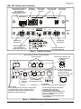
LEDs, DIP Switches and Connectors
Front Panel DIP Switches for
Data & Phone Functions
(FXS card shown)
The FXO card differs only on
DIP Switches #5, 7 & 8
DATA
PHONE MUX-fxs
RX
DATA
RMTLB
LOCLB
SIGGEN
Phone Channel
LED Status
Indicators
Data Signal
LED Indicators
PHONE
Power Supply
LED Indicators
PHONE
HOOK
TX
1
2
3
4
Hook & Ring Status
LED Indicators
1
2
3
4
RING
1
2
3
4
1
2
3
4
Phone
Card
PWRA
PWRB
Vcc
RING CAD
RG TST
RxB
TxB
ON
1
2
DIS ALM
RMTLB
TCCOMM.COM
Made in U.S.A.
TxA
PHONE + DATA +
ETHERNET MUX
3
RxA
Ethernet
+
Data
Card
4
LED-DATA
LOCLB
Optical Board
LED Indicators
Optical Board
LED Indicators
TxB and RxB: Redundant
Optic Transmitter “B”
(on dual optic models only)
TxA: Optic Transmitter “A”
RxA: Optic Receiver “A”
Figure 2. TC8520 Front Panel
RJ-11 Connectors for POTs or 2/4 Wire 600 Ohm
signal connections
Note 1: POTs signals use only
the middle two pins.
RJ-11 JACK
654 321
12VDC
24VDC
CH1
ALM
RLY
12VDC
48VDC
RS-232
AUX1
24VDC
125VDC
Dry contact
alarm relay
connector.
CH2
CH3
RS-422
AUX2
CH4
RS-485
AUX3
AUX4
Note 2: The Base card uses RJ-45
connectors for AUX1-AUX4
for Data connections.
Please refer to Chapter 5 for
Virtual Pin connections.
RJ-45 Connectors for
electrical signal connection.
DC Power Input:
A is for primary power; B is for backup. Only one input
is required to power the unit. If power sources are
connected to both A & B, power redundancy will be
utilized (both A & B share the load).
RJ-45 Female
Reset Button:
Used to reset the unit to default configurations.
To reset the original default configurations;
1. Unplug the power to the unit.
2. Push and hold the “Reset Button.”
3. While holding the button in, Plug the power
back “on”, wait approximately 6 seconds,
then release the button.
4. The original factory default configurations
will be restored.
Figure 3. TC8520 Rear Panel with Terminal Blocks
-9-
TC8520 User's Manual
Rev. 1.8
RJ-11 Connectors for POTs or 2/4 wire analog 600 Ohm
signal connection
Note: POTs signals use only
the middle two pins.
12VDC
24VDC
CH1
CH2
CH3
RJ-11 JACK
CH4
ALM RLY
12VDC
48VDC
65432 1
24VDC
125VDC
Dry contact alarm
relay connector.
Reset Button:
Used to reset the unit to default configurations.
DC Power Input:
A is for primary power; B is for backup. Only one input
is required to power the unit. If power sources are
connected to both A & B, power redundancy will be
utilized (both A & B share the load).
To reset the original default configurations;
1. Unplug the power to the unit.
2. Push and hold the “Reset Button.”
3. While holding the button in, Plug the power
back “on”, wait approximately 6 seconds,
then release the button.
4. The original factory default configurations
will be restored.
Figure 4. TC8520 Rear Panel with Serial DB9 Connector
- 10 -
Optic Board (10/100 Base-T Card) LEDs and DIP Switch Functions
TC8520 User's Manual
Rev. 1.8
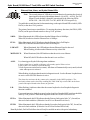
Ethernet, Data, Alarm, and Optical Status LEDs
Note : The second column of LEDs have a second function. It monitors the electrical
input signal for the optical board data channels 1-4 (AUX1...AUX4). The "IN"
(Input) of each channel 1 through 4 is monitored by the following LEDs:
ALM=CH1 , LB=CH2, FEF-A=CH3, & FEF-B=CH4 respectively.
To enable this second function for data monitoring, set the optical board DIP switch #4 (LEDDATA) to the down "On" position.
The primary functions are stated below. To monitor the primary functions, the SW#4 (LEDDATA) on the optical board must be to the up "Off" position.
100M:
When illuminated, this LED indicates that the Ethernet Port is 100Mbps.
When Off, it indicates that the Ethernet Port is 10Mbps.
FULL:
When illuminated, this LED indicates that the Ethernet Port is Full Duplex.
When Off, it indicates that the Ethernet Port is Half Duplex.
LNK/ACT:
When illuminated, this LED indicates that an Ethernet Signal is detected.
When Flashing, it indicates that Ethernet activity is detected.
MSTR/SLVE:
When illuminated, this LED indicates that the unit is set as a Master.
When Off, this LED indicates that the unit is set as a Slave.
ALM:
Lit, when triggered by the following alarm conditions:
1. Optic signal lost or invalid on Primary or Secondary optical fiber receiver.
2. Any of the voice modules is malfunctioning.
3. Loss of power on a unit (local or remote) - this alarm will automatically reset (cancel) on both
units when power is restored.
When flashing, it indicates that the unit is in diagnostic mode: Local or Remote Loopback tests
are active or the SIGGEN function is active.
The alarm also activates the dry contact relay (normally in the OPEN position). The
local unit's alarm can be cleared by enabling the "DIS ALM" dip switch SW1 on the front
panel of the optical board to the down (on) position.
LB:
When flashing, it indicates that either the remote loopback or local loopback diagnostic
function is enabled.
For normal operation, both the remote loopback and local loopback DIP switches should be
in the up "Off" position. When both diagnostic modes are off, the LED will be off.
FEF-A:
When illuminated, this LED indicates that the Primary link (optical side "A"), far end, has
detected a fault condition. (Either the Local TxA or Remote RxA is bad.)
FEF-B:
When illuminated, this LED indicates that the Secondary link (optical side "B"), far end, has
detected a fault condition. (Either the Local TxB or Remote RxB is bad.)
Note: By default, Far End Fault Detection will only be enabled on units with optical redundancy.
- 11 -
TC8520 User's Manual
Rev. 1.8
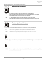
Data, Optical & Power Status LED Indicators
Note : The first column of LEDs have a second function. It monitors the electrical
output signal for the optical board data channels 1- 4 (AUX1...AUX4). The
"OUT" (Output) of each channel 1 through 4 is monitored by the following
LEDs: Rx-A=CH1, Rx-B=CH2, USE-B=CH3, & SYNC=CH4 respectively.
To enable this second function for data monitoring, set the optical board DIP switch
#4 (LED-DATA) to the down "On" position.
The primary functions are stated below. To monitor the primary functions, the SW#4
(LED-DATA) on the optical board must be to the up "Off" position.
PWR A & B :
Indicate the status of dual power sources at the power jacks on the rear panel (9V to
12V DC). Note: when power redundancy is utilized, both "A" and "B" LEDs will be
lit. Normally, both "A" and "B" share the load; if either power source fails, the other
assumes the full load.
Vcc1 & 2:
+5V DC status. There are two separate voltages derived from the power source on the
Optic Board. These LEDs indicate the presence of these voltages. Both should be lit
whenever power is connected to the unit.
Rx-A:
When illuminated, this LED indicates that the Primary Optical Receiver (side "A") is
receiving the signal above minimum sensitivity threshold.
Rx-B :
When illuminated, this LED indicates that the Secondary Optical Receiver (side "B")
is receiving the signal above minimum sensitivity threshold.
USE-B:
When Off, it indicates that the active link is the Primary optical side (side "A"). When
illuminated (On), it indicates that the active link is the Secondary optical side (side "B").
SYNC:
When illuminated, this LED indicates that the fiber link has been established between
the local and remote units.
When flashing, it indicates that the fiber link is broken between the local and remote
units. If the units are ordered with optional, optical redundancy, then it would take both
the primary and secondary optical port A and B to be broken for the SYNC LED to
flash.
ON
1
2
DIS ALM
RMTLB
3
4
DIP Switch Functions
LED-DATA
LOCLB
DIS ALM:
Disables the alarm buzzer and the dry contact relay when enabled to the down (on)
position.
RMTLB :
Used to enable the RMTLB function for testing the data channels. All four data channels
on the optical board will be in remote loopback mode at the same time.
LOCLB:
Used to enable the LOCLB function for testing the data channels. All four data channels
on the optical board will be in local loopback mode at the same time.
LED-DATA:
Used to monitor the default functions of the dual function LEDs or the Input/Output
status of the electrical channels on the optical board, see notes on pages 11 & 12.
- 12 -
TC8520 User's Manual
Rev. 1.8
Interface (Telephone) Board LEDs and Functions
DATA
RX
Data Signal Status LED Indicators
TX
1
2
3
4
RX:
Rx (input to the Optical Card) status indicators for each data channel.
Solidly lit, it indicates that the data signal is received from the local user's equipment.
Off when, data signal is not received from user's equipment.
TX:
Tx (output from the Optical Card) status indicators for each data channel.
Solidly lit, it indicates that the data signal is transmitted to the local user's equipment.
Telephone Signal Status LED Indicators
1
2
3
4
Volume LED indicators for the RJ-11 connections for each phone channel:
IN:
"IN" electrical signal input to the Telephone Card from the user's device.
OUT:
"OUT" electrical signal output from the Telephone Card to the user's device.
HOOK
1
2
3
4
HOOK:
Hook status indicators (for each phone channel). This LED will light up when the phone is off
hook.
RING
1
2
3
4
RING:
Ring status indicators (for each phone channel). This LED will flash when the "ring signal" (from
the remote FXO unit) is detected.
- 13 -
TC8520 User's Manual
Rev. 1.8
Power Status LEDs
PWRA
PWRB
Vcc
PWR A & B :
Indicate the status of dual power sources at the power jacks on the rear panel (9V to
12V DC). Note: when power redundancy is utilized, both "A" and "B" LEDs will be
lit. Normally, both "A" and "B" share the load; if either power source fails, the other
assumes the full load.
Vcc:
+5VDC LED status indicator. Indicates the voltage is derived from the power source
on the Interface Board. It should be lit whenever power is connected to the unit.
Not Used:
The LED indicator below the Vcc, is not used. It should be off at all times.
DIP Switches on FXS Card
DATA
RMTLB
LOCLB
SIGGEN
FXS & FXO Card's DIP Switch Functions
DIP Switches on FXO Card
DATA
PHONE
RMTLB
LOCLB
SIGGEN
RING CAD
RG TST
PHONE
RING BLK2
RING BLK1
OFHK
Note: DIP Switches #4, 6, & 8 on FXS card and DIP Switches #4 & 6 on FXO card are not used.
RMTLB :
Initiates a Remote Loopback for testing data. It loops back the data at the remote unit
back to the user's equipment. When done with the test, return SW1_1 to the up "Off"
position.
LOCLB:
Initiates a Local Loopback for testing the incoming electrical data signal on the local
unit. The incoming data signal is looped back to the device connected to the RJ-11.
When done with the test, return SW1_2 to the up "Off" position.
SIGGEN:
Signal Generator, used for validating fiber optic links. (see page 21 for SIGGEN test).
RG TST:
Ring Tester (On FXS Card), it will ring every phone channel on the card simultaneously.
RING CAD:
Ring Cadence (On FXS Card), is used to change the ring sound: Must be in the up "Off"
position on both units when using the FXO to FXS setup. (For future release)
OFHK:
Off Hook (On FXO Card), (for factory test only, not for user).
RING BLK1 &
RING BLK2:
(On FXO Card), these DIP switches are used to set the ringing length of the phone set.
However, any change selected by the user, will be done internally within the board, user
will not note the difference in ringing length. Please keep at factory default setting. See
example, below. (For factory troubleshooting)
SW1
SW1
SW1
SW1
SW1 Settings
for RING BLK1
and RING BLK2
RING BLK2
RING BLK1
Longest ringing
length
RING BLK2
RING BLK1
Longer ringing
length
- 14 -
RING BLK2
RING BLK1
Shorter ringing
length
RING BLK21
RING BLK1
Shortest ringing
length
“FACTORY DEFAULT SETTING”
Base (Optical) Card Internal DIP Switch (SW2)
TC8520 User's Manual
Rev. 1.8
These DIP switches have been set by factory. If any changes need to be made, contact the Technical Support
Department before doing any changes to not void the warranty.
SW2_1: Not used.
SW2_2: Enable data port.
SW2_3: Enable optical redundancy (RxB).
SW2_4: Not used. (For factory test only)
Expansion (Telephone) Card Internal DIP Switch (SW2)
These DIP switches have been preset by factory. If any changes need to be made, contact the Technical
Support Department before doing any changes to not void the warranty.
SW2_1: FXS/FXO selection for channel 1.
On: for FXO, Off: for FXS (Not for user use)
SW2_2: FXS/FXO selection for channel 2.
On: for FXO, Off: for FXS (Not for user use)
SW2_3: FXS/FXO selection for channel 3.
On: for FXO, Off: for FXS (Not for user use)
SW2_4: FXS/FXO selection for channel 4.
On: for FXO, Off: for FXS (Not for user use)
SW2_5: Disable channel 2.
(default position: Left "Off", unless less than four channels ordered)
SW2_6: Disable channel 3.
(default position: Left "Off", unless less than four channels ordered)
SW2_7: Not used.
SW2_8: Disable channel 4.
(default position: Left "Off", unless less than four channels ordered)
- 15 -
TC8520 User's Manual
Rev. 1.8
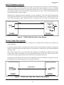
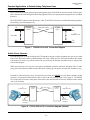
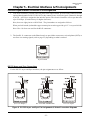
Optical Redundancy (optional)
If optic redundancy was ordered with the unit, Figure 5 below applies to its operation. Optic redundancy is
used to prevent the loss of data transmission in the event an optic cable, transmitter, or receiver is broken
or degraded. Should this occur, the secondary optic link & receiver "B" is enabled automatically, thereby
preserving the integrity of the communication. In the meantime, the "Alarm" LED will flash and the buzzer
will sound to indicate a cable breakage.
When the unit is equipped with optic redundancy, the optic transmitter "TxA" and "TxB" both transmit the
same signal to the remote unit. It is up to the remote unit to decide whether "RxA" or "RxB" should be used
as the valid incoming optic signal. By default, "RxA" is the primary receiver; "RxB" is the standby backup.
RxA
TxA
Optic Signal
Detector
&
Automatic
Switchover
Control
Tx
TxB
RxB
TC8520
Rx
TC8520
Figure 5. TC8520 (with Dual Optics) Logic Diagram
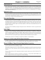
Two-way "Single Fiber" (optional)
As an option, the TC8520 supports two-way "Single Fiber" communication to distances up to 100km over
single mode fiber.
It is ideal for situations where existing fiber optic cable capacity is limited. Because it doubles existing cable
capacity by transmitting bi-directional signals over a single fiber, it eliminates the need to install additional
fiber optic cable.
The TC8520 "Single Fiber" uses a Fiber Optic Wavelength Division Multiplexer (WDM) which enables
1310nm and 1550nm wavelengths to be transmitted simultaneously on the same fiber optic cable. The
direction of the optical signals can be in the same direction or opposite directions.
Transparent to incoming data, the "Single Fiber" WDM option, effectively doubles existing cable capacity
by multiplexing two separate channels over one single mode fiber.
1300/1550nm
Tx/Rx
Tx/Rx
Single Fiber Strand
TC8520
TC8520
Figure 6. TC8520 (with "Single Fiber" Option) Logic Diagram
- 16 -
Chapter 2 - Installation
TC8520 User's Manual
Rev. 1.8
Unpacking the Unit
Before unpacking any equipment, inspect all shipping containers for evidence of external damage caused
during transportation. The equipment should also be inspected for damage after it is removed from the
container(s). Claims concerning shipping damage should be made directly to the pertinent shipping agencies.
Any discrepancies should be reported immediately to the Customer Service Department at TC Communications, Inc @ (949) 852-1973.
Equipment Location
The TC8520 should be located in an area that provides adequate light, work space, and ventilation. Avoid
locating it next to any equipment that may produce electrical interference or strong magnetic fields, such as
elevator shafts or heavy duty power supplies. As with any electronic equipment, keep the unit from excessive
moisture, heat, vibration, and freezing temperatures.
Dry Contact Alarm Relay
A terminal block connector labeled "ALM RLY" at the rear panel of the optical board provides for the Dry
Contact Alarm Relay. Normally in the OPEN position, any alarm condition will force the relay switch to the
CLOSED position (the "Alarm" LED will light and the audio buzzer will sound). This relay can be used in
conjunction with an external device to monitor the TC8520's operation. The alarm switch will only be
activated when the TC8520 is under a true alarm condition; it will not be activated when the unit is in a
diagnostic (test) mode.
This function can be disabled by setting the front panel switch 1 "DIS ALM" to "down" (on) position on the
optical card.
Power Supply
The TC8520 unit is powered via rear panel's connector. There are two pairs of connectors ( "PWR A" and
"PWR B" ) for power redundancy. Depending on the power option ordered, it could be one of following:
12VDC standard or optional 24VDC power supply. When AC power is ordered, a universal external power
adapter is supplied which can support AC 90 VAC to 240 VAC and 50 Hz to 60 Hz. When unit contains
more than one card, only one pair of power connectors needed to connect to a power source.
Alternate power sources are available as an option (see Chapter 8 - Specifications).
Telephone or 2/4 Wire Analog 600 Ohm Signal Connections
As Figure 3 on page 9 illustrates on the upper (phone) board, four RJ-11 connectors are provided to connect
two wire telephone (POTs) or 2/4 wire analog 600 Ohm signals (depending on what is ordered).
Ethernet 10/100Base-T Signal & Electrical Signal Interface Connections
The lower (optical) board as illustrated on Figure 3 on page 9 an RJ-45 female connector provides for the
electrical connection for the 10/100Base-T signal.
The four RJ-45 connectors (AUX1 - AUX4) for channels 1 through 4 are provided for electrical connections
for data. For RJ-45 pin assignment connections on the optical board connectors (AUX1-AUX4), refer to
Chapter 5.
The type of data interface will be dependent on what the customer orders such as RS-232, RS-422, TTL,
or Dry Contact.
Note: The DB9 connector (Console port connector), as in Figure 4, is only used to set the IP address, user
name, and password. Please refer to page 42 for Console Settings.
- 17 -
TC8520 User's Manual
Rev. 1.8
System Start Up
When power is initially connected to the TC8520, all LEDs will flash for a few seconds and the audio buzzer
will sound. Once the unit passes its power up diagnostic phase, the following LED status should be observed
from the front panel:
Interface Board:
1. The POWER "A" and/or "B" LED should be lit (depending on which power jacks are connected).
2. The "Vcc" LED should be lit (indicating +5V voltage is derived from Power "A" and/or "B").
3. All other LEDs can be in a random state (either On or Off) as the TC8520 will set its LEDs accordingly once
valid electrical and optical connections are present.
Optical Board:
1. The "Rx-A," ("RxB," on dual optic models) and "SYNC" LEDs will flash (indicating no optic signal
connections).
2. The "ALM" major alarm will be lit (indicating no electrical or optic signal connections).
3. The "MSTR/SLVE" LED will be lit if the unit is set as Master unit. When Off, it indicates that the unit has
been set as a Slave.
4. The "Vcc1" & "Vcc2" LEDs should be lit (indicating +5V voltage is derived from the power supply).
5. All other LEDs can be in a random state (either On or Off) as the TC8520 will set its LEDs accordingly once
valid Ethernet and optical connections are present.
Installation Procedure Summary
The TC8520 is designed for quick and easy installation. Before installing, however, double-check the LED
settings on each of the channels on the interface board and the DIP switches on the optical board to verify that
they are in the correct positions.
1. By factory default all units will be set as Master units. Before connecting two units via fiber cable, the user
must configure one of the TC8520 units to be a Slave unit. Please refer to the "Read Me First" instructions
sheet included and/or refer to the Web configuration section, page 26.
2. Connect fiber optic cables between the local & remote units; the local unit's optic "TxA" connects to the
remote unit's optic "RxA" (and "TxB" to "RxB" on dual optic models). Observe that the "SYNC" (and "USEB" on dual optic models) LEDs lights solid when a good optic connection is present.
3. The FXO unit should be connected to a PBX and the FXS unit connects to analog telephone sets.
4. For Ethernet (10/100Base-T) signals, connect the Cat5 or Cat5E cable proving the Ethernet signal to the RJ45 connector on the rear panel on the optical board on the TC8520. Observe that the 100M, FULL LEDs
are lit, and the LNK/ACT LED is flashing.
If the Ethernet signal is 10Base-T and half duplex, the 100M and FULL LEDs should be off. If the Ethernet
signal is 100Mbps and full duplex, the 100M and FULL LEDs should be lit.
5. For serial data signals (RS-232, RS-422, TTL, or Dry Contact) connect the electrical signals to AUX1AUX4 on the optical card, refer to page 9 figure 3 & Chapter 5 for electrical connections & pin assignments.
To monitor the input/output status of the data signals, please refer to the notes on pages 11 and 12.
5. For 2/4 wire 600 Ohm signals, use the RJ-11 connectors on the phone card to connect the electrical signals.
Refer to Chapter 5 for virtual pin connections & assignments.
6. Verify System Integrity:
At each unit, check that the "SYNC" and Rx-A ("Rx-B" and "USE-B" on dual optic models) LEDs lights solid
indicating good optical connections.
Verify and record the optical cable loss for each link in the application after installation is complete. This
reading will both verify the integrity of the circuit and provide a benchmark for future troubleshooting efforts
(see Chapter 3 - Troubleshooting).
- 18 -
TC8520 User's Manual
Rev. 1.8
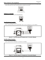
Standard Applications to Extend Analog Telephone Lines
Phone Line Extension
The TC8520 can be used to extend regular analog phone lines from a PBX to remote location via fiber optic
cable. Because the TC8520 digitizes the analog signals (PCM), voice quality does not degrade over extended
distances.
The TC8520 FXO connects to the phone line, while TC8520 FXS connects to a traditional analog telephone
sets (POTS, plain old telephone set).
TIP
TC8520
(FXO)
RING
fiber optic cable
Tx
Tx
TC8520
(FXS)
TIP
RING
Rx
Rx
to
Telephone Set
from PBX
TIP
TIP
RING
RING
Figure 7. TC8520 FXO to FXS Connection Diagram
Hotlink Phone Extension
By connecting two TC8520s configured as FXS together using two regular telephone sets, the users at both
sides of the fiber link can have a hotlink phone line setup. When one user lifts up the handset, the remote
side phone will start to ring. When remote side user picks up the handset, the phone stops to ring and the
conversation begins.
When conversation is over any user can replace the handset to hook to terminate the phone link. If either
party places the handset to hook and the other does not hang up, the phone on hook will continue to ring.
Remember, when using this set up, one and only one of the units MUST be set as Master and the second
as a Slave. To set up one of the units as a Slave, refer to the web configuration section, page 31. The MSTR/
SLVE LED will be lit on the front panel of the master unit and Off on the Slave unit. It doesn't matter which
unit is set to Master.
to
Telephone Sets
TIP
TC8520
(FXS)
Tx
fiber optic cable
Tx
Rx
Rx
TC8520
(FXS)
to
Telephone Sets
TIP
RING
RING
To FXS
connectors
1 through 4
To FXS
connectors
1 through 4
Figure 8. TC8520 FXS to FXS Connection Diagram (Hotlink)
- 19 -
Chapter 3 - Troubleshooting
TC8520 User's Manual
Rev. 1.8
General
Alarm conditions occur whenever an optical or electrical problem or "fault" conditions are detected by the
TC8520.
The Ethernet 100M, & FULL LEDs on the optical board should be Off, if the Ethernet signal is 10Base-T
and half duplex. If the Ethernet signal is 100Mbps and full duplex, the 100M and FULL LEDs should be lit
and the LNK/ACT LED should be flashing as it detects Ethernet activity.
All LEDs are Off
If no LEDs are lit on the unit, check the DC power supply, connector plug, and/or the power source. If the
problem persists, contact the Technical Support Department at TC Communications, Inc @ (949) 852-1973.
"ALM" LED on the Optical Board
When an alarm condition is detected, the "ALM" LED will light, the audio buzzers will sound, the dry contact
relay will close, and one or more additional LED will light or flash. The following fault conditions will cause
the alarm to be triggered on the optical board:
1. Optic signal lost from "RxA" (or "RxB" on dual optic models).
2. Optic signal is marginal, which causes invalid data packets to be received; the "Rx-A" (or "Rx-B") LED
will be flashing.
3. The remote unit lost power.
Optic Cable Types
Conventionally, fiber optic cable with yellow-colored insulation is used for Single Mode applications; gray
or orange-colored insulated cable is for Multimode use. If Multimode cable is used in a Single Mode
application, the test results could be erroneous and confusing.
Calculating the Loss on the Fiber
The fiber optic link and/or connectors are frequently the source of various problems. Check out the
connectors and the integrity of the link first. Ideally, the link should be calibrated for total loss after the
installation has been completed. This will accomplish two things: (1) it will verify that the total loss of the link
is within the loss budget of the device and (2) it will provide a benchmark for future testing. For example,
a system that has been tested as having 6dB total loss when installed and suddenly tests out as having a loss
of 10dB probably has a connector or link problem.
These are the reference values we use to calculate the loss on the fiber:
Multimode 850nm
:
3 dB loss per km on 62.5/125µm cable*
Multimode 1310nm
:
2 dB loss per km on 62.5/125µm cable*
Single Mode 1310nm
:
0.5 dB loss per km on 9/125µm cable*
Single Mode 1550nm
:
0.25 dB loss per km on 9/125µm cable*
*These numbers are listed for reference only. We recommend an OTDR reading be used to determine actual link loss.
- 20 -
Chapter 4 - Bench Tests
TC8520 User's Manual
Rev. 1.8
Ethernet/Web Page Test
The purpose of this test is to verify Ethernet channel and accessibility to the web page using a PC.
1. Power on the units and configure the IP address on the units, refer to Chapter 6.
2. Connect the fiber optical cables from the local to remote unit and vise versa.
3. Verify that the Sync LED is lit.
4. Connect one of the TC8520 units to a PC to access the web page using the a web browser (enter the
IP address configured in step 1).
5. You should be able to access the local and remote TC8520 unit's web page while connected to the local
unit.
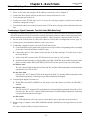
Conducting a Signal Generator Test (On Units With Data Only)
The purpose of the Signal Generator Test is to verity the optical connections between the Master and Slave
units (each unit has its own built-in channel-scanning optic signal generator) and the clock signal of each unit.
Alarm conditions occur whenever an optical problem or "fault" condition is detected by the TC8520s.
1. Set one of the TC8520 units as a Slave unit. (Refer to TC8520 Slave Configuration section, page 31)
2. Connect power to both Master and Slave units to be tested.
3. Conducting a Signal Generator test on the TC8520 Master unit.
a. Connect short fiber optic patch cords, using the correct type of fiber corresponding to the wavelength
of the units, between the Master and Slave units.
b. Connect the optic Tx of the Master to the optic Rx of the Slave and optic Tx of the Slave to optic
Rx of the Master.
c. All the front DIP switches on the TC8520s must be set to the up "off" position.
d. Enable the Signal Generator by flipping DIP switch SW3 (SIGGEN) down on the front panel of the
phone card also enable DIP switch SW4 (LED-DATA) on the optical card. (card with optics)
On Master unit:
The "IN" channel LEDs on the Optical Card and "Rx" channel LEDs on the phone card should light
sequentially from CH1 to CH4.
On the Slave unit:
Likewise, the "OUT" channel LEDs on the Optical card and "Tx" channel LEDs on the phone card
should light sequentially, indicating receipt of the transmitted clock signal.
4. Completing the Signal Generator test.
a. Enable DIP switch SW1 (RMTLB) on the phone card of the Master unit while the SIGGEN is
enabled.
On Master unit:
The "IN" and "OUT" channel LEDs on the Optical Card should light sequentially from CH1 to CH4.
Likewise, the "Rx" and "Tx" channel LEDs on the Phone Card should light sequentially, indicating
receipt of the transmitted clock signal.
On Slave unit:
The LED indications will be the same as on the Master unit as described on step #4 above.
5. When testing is complete, return SW1 (RMTLB) and SW3 (SIGGEN) to the up position on all units
tested.
All "other" channel LEDs are not used for this test.
- 21 -
TC8520 User's Manual
Rev. 1.8
Ring Test (FXS unit only)
When SW5 " RG TST" switch is in the down ("On") position, the FXS Card will try to ring every channel
simultaneously to verify the integrity of the ring signal.
Local Electrical Loopback Test on the TC8520s (On Units With Data Only)
The purpose of this test is to verify the interface's input and output connections, signal receiver and signal
output driver.
This test can be enabled by either DIP switch SW3 (LOCLB) on the optical card or DIP switch SW2
(LOCLB) on the phone card.
1. Set the front panel DIP switch SW3 to the "On" (down position) on the optical card.
2. Enable DIP switch SW4 (LED-DATA) to the "On" (down position) to monitor the data status.
3. Connect a Bert Tester to CH1 through CH4 to monitor the data status on each channel respectively. The
incoming electrical signal is looped back to the device connected to the RJ-11.
This verifies good electrical signal connections.
4. When done with the test, return SW3 or SW2 as well as SW4 to the up "Off" position.
Local Optical Loopback Test on TC8520 "Slave Units" Only (On Units With Data Only)
The purpose of this test is to verify the transmitted and received optical signal.
To perform this test, the TC8520 unit must be configured as a Slave unit first. Refer to TC8520 Slave
Configuration section, page 31 to set the TC8520 as a Slave unit.
1. Enable DIP switch SW4 (LED-DATA) to the On ("down" position) to monitor the data status.
2. Use a short fiber optic jumper to connect from optic Tx to optic Rx to form a self-loopback on the same
unit.
3. Connect a Bert Tester to CH1 through CH4 to monitor the data status on each channel respectively.
4. The incoming signal from the user's equipment should be looped back through the optical fiber back to
the user's equipment.
Note, the channel 1 through 4 "IN" and "OUT" LEDs will light according to which channel is being tested.
5. When done with the test, return SW4 (LED-DATA) to the up "Off" position.
Note, you may leave SW4 (LED-DATA) to the down "On" position if for monitoring the data status of each
channel.
- 22 -
TC8520 User's Manual
Rev. 1.8
Chapter 5 - Electrical Interfaces & Pin Assignments
Electrical Signal Interface Connection & Pin Assignments
1. Four RJ-45 connectors, located at the rear panel of the Optical board, provide for the connection of the
optional data channels for RS-232, RS-422, or dry contact closure electrical signals. Channels 1 through
4 (AUX1 - AUX4) are assigned to the interface option. The electrical interface will accept data rates
up to 38.4 Kbps. (Consult factory for higher data rates).
Note, there are eight pins in an RJ-45 Jack. The pin numbers are assigned as follows:
When you look into the jack and the copper contact pins are at the upper side, pin "1" is on your left side.
Note: Pins 1 & 8 are not used for the RJ-45 connectors.
2. The four RJ-11 connectors on the Phone board, are provided to connect two wire telephone (POTs) or
two/four wire Analog signals (refer to page 25), depending on what is ordered.
1 2 3 4 5 678
RJ-45 JACK
RJ-45 Female
RS-232 Async and Sync Connections
For the RS-232 Async and Sync interfaces, the pin assignments are as follow:
12 34 5 67 8
1 2 3 4 5 67 8
12 3 4 5 67 8
RJ-45 JACK
RJ-45 JACK
RJ-45 JACK
(RS-232 Async)
RS-232 with handshake
RS-232 Sync
Figure 9. RS-232 Async and Sync Pin Assignments & Virtual Connection Diagrams
- 23 -
TC8520 User's Manual
Rev. 1.8
RS-422 (Async) Connection
For the RS-422 Async interface, pins 3 and 6 are balanced input pins. Pin 3 is the positive input (TxD+) and
pin 6 is the negative input (TxD-). Likewise, Pins 4 and 5 are balanced output pins. Pin 5 is the positive output
(RxD+) and pin 5 is the negative output (RxD-). Either pin 7 or pin 2 can be used as the signal ground. Only
RS-422 asynchronous communications can be used on the TC8520.
1 2 3 4 5 67 8
RJ-45 JACK
RS-422 Async
Figure 10. RS-422 (Async) Pin Assignments & Virtual Connection Diagram
Dry Contact Closure Detector & Relay Switch
For dry contact closure applications, only uni-direction transmission is allowed. The transmitter side has a
dry-contact closure detector as shown in the diagram below. The receiver side has a dry-contact closure
relay switch. The "close" and "open" status is controlled by a relay switch inside the TC8520. It reflects
the remote detector's "on" and "off" status.
As illustrated below, when the RJ-45's pins 5 and 6 are closed at the transmitter side, the status is reflected
at the remote receiver's side. The relay switch on the receiver's side is rated 0.5A DC switching current,
with a max load rating of 10VA.
TC8520 with Dry Contact Closure Detector
(dry contact closure)
5V DC
RJ-45 JACK
8.2ma
8 ma DC
0V or 5V DC
TTL logic signal
4,5
4,5
2,3,6,7
3,6
FIBER CABLE
transmitter
Figure 11. Dry Contact Detector and Closure Logic Diagrams
- 24 -
RJ-45 JACK
receiver
TC8520 User's Manual
Rev. 1.8
Phone Card RJ-11 Pin assignments
The 4 x RJ-11 connectors on the rear panel can be used for two wire telephone (POTs) or 600 Ohm analog
signals (dependig on the type of interface that the customer has ordered).
RJ-11 JACK
654321
The first pin is on the right side
when you look into the jack with
all the metal contacts at lower side
Telephone Connection
Only the middle two pins are used to connet phone lines.
RJ-11 JACK
65432 1
Four Wire Analog Connection
For four wire analog audio signals:
Pin 5 is transmit TIP & pin 2 is transmit RING. Pin 4 is receive TIP & pin 3 is receive RING.
RJ-11 JACK
RJ-11 JACK
RJ-11 JACK
654321
Figure 12. Four Wire Analog Pin Assignments & Connection Diagram
Two Wire Analog Connection
For two wire analog audio signals:
Pin 4 is transmit/receive TIP & pin 3 is transmit/receive RING.
RJ-11 JACK
RJ-11 JACK
RJ-11 JACK
654321
Figure 13. Two Wire Analog Pin Assignments & Connection Diagram
- 25 -
Chapter 6 - Software Configuration
TC8520 User's Manual
Rev. 1.8
Configure your TC8520
Software configuration is done through the management web page by connecting to the RJ-45 Port on the
rear. Configuring the TC8520 using the web page will overwrite the current hardware settings. The new
settings will reflected on the front LED's.
In order to configure the TC8520 set to default, the user needs to use a PC with a web browser installed.
The default IP address is: 192.168.254.123. The PC's IP address must be set within the range of
192.168.254.1 to 192.168.254.254, and with a Network Mask of 255.255.255.0. If your PC does not have
a compatible IP Address and Network Mask, or you are not sure about the settings, refer to the "PC IP
Configuration" section on page 41 for more detail. You can also change the IP address of the TC8520 by
matching it up with that of you PC, refer to Console settings on page 42.
To configure the TC8520, simply enter the IP address of the TC8520 in the Web browser's address box. For
Example, http://192.168.254.123.
(Attention: Contact your network administrator if you are unsure about the settings. Improper settings may
result in disruption of the existing network.)
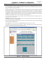
Once you enter the IP address and click Enter, you will see a verification window, where you will be prompted
to enter a username and password:
enter admin under User Name and enter password under Password and click "OK."
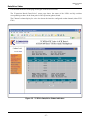
You will then see the following window as in figure 14, below. This summary page will show you the current
configuration and the status of the TC8520 media converter.
Figure 14. TC8520's Summary
- 26 -
TC8520 User's Manual
Rev. 1.8
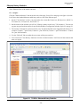
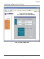
Data/Voice Status
Use the links at the left of the page to navigate to the desired section.
The "Expansion Board (Data/Voice)" status page shows the status of the LED's and dip switches
corresponding to those on the front panel of the expansion (phone) board.
The 'Channel' column display for voice also shows the interface configured on that channel (either FXS/
FXO)
Figure 15. TC8520's Data/Voice Status Indicators
- 27 -
TC8520 User's Manual
Rev. 1.8
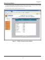
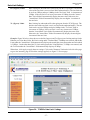
Ethernet History Statistics
The "Ethernet Statistic" link on the left side of the page is used to monitor the status of the bandwidth usage
of the Ethernet Port of the media converter.
For example:
Click the "Ethernet Statistic" link on the left side of the page. You will see the page as in figure 16, below.
It will show the bandwidth status and history and/or event of the Ethernet port.
1. On the "Current Rate" section, you can monitor the current Rx Frames/sec, Rx Bytes/sec, Rx BU %,
Tx Frames/sec, Tx Bytes/sec, and Tx BU %.
2. On the center of the window you will see "History counter record every "30" minute(s)." You can set
up your own preferred time intervals specified in the Basic Configuration window figure 18, on page 30.
3. The counters 1 through 24, each account for every 30 minutes that have been logged into the history. For
example: Counter 1 = past 30 min, Counter 2 = past 2x30 min, Counter 3 = past 3x30 minutes...Counter
24 = past 24x30 minutes.
4. Use the "Refresh" link to update the new status of the port statistics.
5. You can use the "Clear History" button to clear the recorded counters. It will clear all the counters and
start over again.
Figure 16. TC8520's Ethernet History Statistics
- 28 -
TC8520 User's Manual
Rev. 1.8
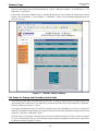
Ethernet Event Statistics
Click the "Ethernet Statistic" link on the left side of the page. You will see the window as in figure 16 on page
28. It shows the bandwidth status and history and/or event of the Ethernet port. Click on the "Event" link on
the middle of the page and you should see the window as in figure 17 below.
It will show all the statistics of the Ethernet port activities.
Figure 17. TC8520's Ethernet Port Event Statistics
- 29 -
TC8520 User's Manual
Rev. 1.8
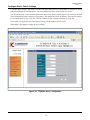
Configure Basic Switch Settings
Click the "Basic Setting" link on the left side of the page and you will see the window as in figure 18, below
and you can begin the configurations. You may change the values of the fields as you like.
The "Record Period" field is used to set the time intervals for history status purposes. You can set the time
intervals anywhere from 1 minute to 120 minutes. The default interval is 30 minutes. There are 24 counters
to record the BU% history. (See the "History counter record" example on figure 16, page 28).
Note: After you apply the new time interval setting, all the counters will be reset.
When done, click Apply to apply the new settings.
Figure 18. TC8520's Basic Configuration
- 30 -
TC8520 User's Manual
Rev. 1.8
Configure Network/IP Settings
Use the links at the left of the page to navigate to the desired section.
To configure the network settings, click the "Network Setting" link on the left side of the page. On the IP
settings window, enter the IP address, Subnet Mask and Default Gateway as shown on figure 19, below.
Note 1: The TC8520 and the monitoring computer should be on the same network ( Contact your network
administrator for valid network settings). When done, click Apply to apply the new settings.
After you have applied the new IP settings on the TC8520, you must change your PC IP settings to be
compatible with the new settings of the TC8520 unit and to be able to continue the configurations.
Figure 19. TC8520's IP Configuration
TC8520 Slave Configuration
By factory default, all units will be set as Master units with default IPs of 192.168.254.123. The TC8520's
work in pairs (one Master & one Slave unit). The user must configure one of the TC8520 units to be a Slave
unit. Please refer to Figure 19, above and/or instructions on the "Read Me First" page included, to configure
one of the units to a Slave unit.
1. One of the units must have a different IP address than that of the Master. To change it, enter the new
IP address (for example, 192.168.254.124) in the "IP Address" field as in Figure 19 and click Apply to
apply the new settings. The Master and Slave units MUST have different IP addresses.
Note:
Please make note of the new IP address you give the Slave unit and keep in a safe place or mark
it on the unit.
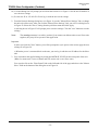
a) After you click Apply, a dialog box as in Figure 20 will appear asking you to reset the unit by
clicking the "reset button" on that dialog box.
(Continue next page)
- 31 -
TC8520 User's Manual
Rev. 1.8
TC8520 Slave Configuration (Continue)
1b) A second dialog box will prompt you to refresh the browser as in Figure 21 for the new IP address to
save the new settings.
1c) Use the new IP or 192.168.254.124 to log in with the new saved settings.
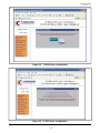
2. From the Network Settings dialog box as in Figure 19, use the "Master/Slave Settings" link to change
the unit to be a Slave unit. After you click the "Master/Slave Settings" link, you will see a dialog box as
in Figure 22. Select the "Slave" setting from the pull down menu and click Apply.
a) A dialog box as in Figure 23 will prompt you to save the settings. Click the "save" button to save the
settings.
Note:
The warning statement is to advise you that if you connect two Master units or two Slave units
together, they may fail to operate in the application.
Important:
b) After you click the "Save" button, you will be prompted to cycle power to the unit to apply the new
settings as in Figure 24.
c) When the power is connected back to the unit, you can log in with the new IP address for the Slave
unit.
3. You can monitor the applied change by noting the MSTR/SLVE LED on the front panel of the unit
(When lit, means unit is set as a Master and Off, means unit is set a Slave unit).
You can also click on the "Base Board" link on the left hand side of the page and observe the "Master
Slave" field on the bottom of the dialog box as in Figure 14.
- 32 -
TC8520 User's Manual
Rev. 1.8
Figure 20. TC8520 Slave Configuration
Figure 21. TC8520 Slave Configuration
- 33 -
TC8520 User's Manual
Rev. 1.8
Figure 22. TC8520 Slave Configuration
Figure 23. TC8520 Slave Configuration
- 34 -
TC8520 User's Manual
Rev. 1.8
Figure 24. TC8520 Slave Configuration
- 35 -
TC8520 User's Manual
Rev. 1.8
Configure Ethernet Settings
Click the "Port Setting" link on the left side of the page to configure the Ethernet Port Settings. After clicking
the "Port Setting" link, you will see the following window shown on figure 25, below.
Port In Use:
Enable or disable either the Ethernet port.
Speed/Duplex:
The speed and duplex on the fiber port is fixed to 100M/Full. You can select the
speed and duplex mode of the Ethernet port as follows:
Auto-Negotiating, 100Mbps/Full Duplex, 100Mbps/Half Duplex, 10Mbps/Full
Duplex, or 10Mbps/Half Duplex.
Current Status:
It shows the current port status for the Ethernet Port.
Figure 25. TC8520's Ethernet Port Settings
Note: When you disable the Ethernet port, you will see that the port is still connected on "Current Status",
however all packets that have been sent through that port will be dropped.
- 36 -
TC8520 User's Manual
Rev. 1.8
Rate Limit Settings
Rx (Ingress) Limit:
Rate limiting for inbound traffic (data going into the TC8520 port). The default
value of the rate limit is zero (no limit on the inbound traffic). The rate limit can
be set from 32Kbps and up to 10Mbps in the "Rx Limit" field in increments of
32Kbps. If the rate limit is set in any increment of 32Kbps, then the "Actual
Rate" limit field will automatically display the same value. Otherwise, the
"Actual Rate" field will automatically display the next higher increment of
the rate limit.
Tx (Egress) Limit:
Rate limiting for outbound traffic (data going out from the TC8520 port). The
default value of the rate limit is zero ( no limit on the outbound traffic). The rate
limit can be set from 32Kbps and up to 10Mbps in the "Tx Limit" field in
increments of 32Kbps. If the rate limit is set in any increment of 32Kbps,
then the "Actual Rate" limit field will automatically display the same value.
Otherwise, the "Actual Rate" field will automatically display the next higher
increment of the rate limit.
Example: Figure 26 below, shows how to set the Rx (Ingress) and Tx (Egress) rate limiting settings for the
Ethernet port. Note that for the Rx Limit setting under "Nominal Rate," 500Kbps was entered, and the Rx
Limit under the "Actual Rate" field automatically displays the next higher increment on the rate limit which
is 512Kbps. On the other hand, the Tx Limit setting under the "Nominal Rate," 512Kbps was entered, and
the Tx Limit under the "Actual Rate" field automatically displays 512Kbps.
When done, click Apply to apply the new settings. Click on the "Summary" link on the left side of the page
to go to the summary page to check the settings applied, see figure 27 on next page.
Figure 26. TC8520's Rate Limit Settings
- 37 -
TC8520 User's Manual
Rev. 1.8
Summary Page
The following diagram shows the Board Status for "Alarm," "Remote Loopback," "Far End Fault-A," "Far
End Fault-A," and "Sync".
It also shows the Optical Status for Opt-A and Opt-B and the rate limit settings for ethernet port "Speed
Duplex," "Rx Limit (Kpbs)," "Tx Limit (Kpbs)," "Link Status," "Alarm," rate limit settings applied on previous
steps on last page.
Figure 27. TC8520's Switch Summary
Link Status for Primary and Secondary Optical Links
You can monitor the status of both Primary optical side "A" (Opt-A) and Optional, Secondary optical side
"B" (Opt-B) on the web browser. The connectivity status for each link will be shown under the "Link Status"
fields as illustrated on figure 27, above.
For example, if both optical sides "A" and "B" are connected for optical redundancy, you will see "Connected"
under the "Link Status" fields. If there are no optical connections on neither optical side, nothing will be shown
in figure 27 under the "Link Status" fields.
The state status of each Opt-A & Opt-B ports can also be monitored under the "State" fields as on figure
27, above. By default the "Opt-A" will be enabled. If optional optical redundancy is ordered, the "Opt-B" will
be shown as enabled in figure 27 above.
- 38 -
TC8520 User's Manual
Rev. 1.8
Configure Login Settings and Levels of Privilege
Click the "Login Setting" link on the left side of the page. You will see the page as in figure 28, below.
Figure 28. TC8520's Configure Login
- 39 -
TC8520 User's Manual
Rev. 1.8
Levels of Privilege
There are three levels of privileges based on users (User 1, User 2, and Admin).
User 1: This user has the lowest privilege of all three levels.
The default username is guest, default password is password and default privilege is to only view the
"Summary," and "Ethernet Statistic" links on the left side of the page as seen on page 28.
User 2: This user has intermediate privilege of all three levels.
The default username is user, default password is password and default privilege is to view the "Summary,"
"Ethernet Statistic," "Basic Setting," "IP Setting," and "Port Setting" links on the left side of the page as seen
on page 30.
Admin: This user has the highest privilege of all three levels.
The default username is admin, default password is password and default privilege is to view all links as
seen on the left side of page 30 such as, "Summary," "Ethernet Statistic," "Basic Setting," "IP Setting," "Port
Setting," "Rate Limit Setting," and "Login Setting."
Note: Only Admin has access to Telnet and/or Console settings.
Figure 28 depicts the Login Settings, there are two sections for changing the usernames, passwords and user
privileges.
The top section of the window is used to change the usernames and passwords of User 1, User 2, and Admin.
After any change to a user, you must click "Apply" on that particular user to apply the new settings. If you
change the username and password of the current Admin, you will see the new authentication windows as
on next page.
The lower section of the window is used to assign the User 1 and User 2 privileges (note: Admin privileges
cannot be changed) . After you make any change, you must click "Apply" on that section to apply the new
settings.
- 40 -
TC8520 User's Manual
Rev. 1.8
Figure 29. New Settings Saved
Figure 30. Login with New Settings
- 41 -
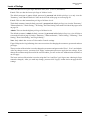
Console Settings (On Units With Data Only)
TC8520 User's Manual
Rev. 1.8
The Console Settings are only used to set the "IP address,"
"user name," and "password").
User Name: Default is admin (you can change it as you wish).
Password: Default is password (you can change it as you wish).
Initial IP setting using the Console:
1.
Connect the computer and the TC8520 via a DB9
serial cable.
2.
Power up the TC8520 unit.
3.
Open the HyperTerminal of your computer and under
properties select the following settings: 9600 Baud,
8 data bits, No parity, 1 stop bit, and None for flow
control. See diagram on the right.
4.
Click "OK" or press Enter, when done.
5.
Press the "Enter" key until you see a "Login" prompt.
6.
Type admin after the Login prompt and press "Enter."
7.
Type password after the "Password" prompt.
Note: You will not see the password characters when typed.
8.
When password has being entered correctly, you will
see: Password Accepted.
9.
At this point, you can continue to enter all the settings, as shown on figure 31 below.
10.
Enter set ip 192.168.1.50 and press "Enter," the IP address will be set and you will be prompted
to type "reset" to apply the new setting. We recommend you reset the settings at the end.
11.
Enter set netmask 255.255.255.0 and press "Enter,"
12.
Enter set gateway 192.168.1.1 and press "Enter,"
13.
Enter set username admin and press "Enter,"
14.
Enter set password password and press "Enter,"
15.
Type "reset" to apply all the settings.
When you see the "TC8520 Console Ver1.0" prompt, you have successfully configured your TC8520 unit.
Figure 31. TC8520's Console Settings
- 42 -
TC8520 User's Manual
Rev. 1.8
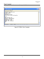
Console Help
The console "help" and "help set" commands will assist you with information about various command
descriptions as shown on figure 32, below.
Figure 32. TC8520's Console Help
Set ip:
Set Unit's IP Address.
E.g. Set ip 192.168.254.123
Set netmask:
Set Unit's Netmask.
E.g. Set netmask 255.255.255.0
Set gateway:
Set Unit's Gateway IP
E.g. Set gateway 192.168.254.1
Set username:
Set login username
E.g. Set username john123
Set password:
Set login password
E.g. Set password 123456
Set default:
Set unit back to factory defaultE.g. Set default
Note1: All set commands required reset to apply new settings
Note2: The default "timeout" value for console setting is two minutes.
- 43 -
TC8520 User's Manual
Rev. 1.8
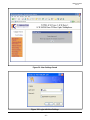
"Show" Command
The "show" command will show the current IP settings of the TC8520 unit.
Figure 33. TC8520's "Show" Command
- 44 -
TC8520 User's Manual
Rev. 1.8
Telnet Settings
You can also use Telnet to set the IP configuration, username, and password.
Note: The Telnet default "timeout" is two minutes.
Figure 34. TC8520's Telnet Settings
- 45 -
Chapter 7 - PC IP Configuration
TC8520 User's Manual
Rev. 1.8
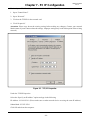
To check your PC's IP Address and Network Mask. (Windows 98/ME)
1. Open “Control Panel”
2. Open “Network”
3. Click on the TCP/IP for the network card
4. Click “Properties”
(Attention: Please copy down the existing setting before making any changes. Contact your network
administrator if you are unsure about the settings. Improper settings may result in disruption of the existing
network.)
Figure 35. TCP/IP Properties
Under the TCP/IP Properties
Select the “Specify an IP address” option and type in the following
IP Address: 192.168.254.1 (Please make sure no other network device are using the same IP address.)
Subnet Mask: 255.255.255.0
Click OK and reboot the computer.
- 46 -
Chapter 8 - Specifications
TC8520 User's Manual
Rev. 1.8
Audio Bandwidth
Telephone .................................................................................................................. 300 Hz to 3.4Khz
Channel Capacity
................... 4 Telephone Channels, 1 Channel Ethernet, and up to four optional data channels
Data Rates
Ethernet ............................................................................................................................ 10/100 Mbps
Async (per channel) ........................................................................................................... 38.4Kbps**
Electrical
Connectors ..............................................................................................................................................
Telephone .................................................................................................................. RJ-11 Female
Data (AUX1 - AUX4) ................................................................................................. RJ-45 Female
10/100Mbps Ethernet .............................................................................................. RJ-45 Female
Data Interface (Optional) ..................................... RS-232, RS-422**, TTL** or Dry Contact**
Ring Frequency .............................................................................................................................. 20Hz
Nominal Ringing Voltage ....................................................................................................... 70VRMS
2-Wire Impedance ................................................................................................................... 600 ohm
Ringer Load(Max REN to drive) ................................................................................................. 3 REN
Voltage between Tip and Ring ....................................................................................................... 48V
Max copper length between phone and the TC8520 .................... 1000 ft(300meters) for 3 REN
Loop current .................................................................................................................................. 20mA
Dial ....................................................... Tone only DTMF(Dial Tone Multiple Frequency), not Pulse
Factory Default Settings
IP Address .................................................................................................................. 192.168.254.123
Optical
Transmitter ........................................................................................................................... LED/ELED
Wavelength .................................................................................................... 850/1310nm Multimode
.................................................................................................................... 1310/1550nm Single Mode
Connector .................................................................................................................. ST* (FC optional)
Loss Budget ................................................................ 15dB Multimode 850/1310nm @62.5/125µm
...................................................................................... 20dB Single Mode 1310/1550nm @9/125µm
System
Bit Error Rate ............................................................................................................ 1 in 10 10 or better
Indicators
System ........................................................... Power A (2 ea.), Power B (2 ea.), Vcc1, Vcc2, Alarm
Optic .............................................................................................................. Sync, Rx-A, Rx-B, USE-B
Channel Status .............................................. Alarm, FEF-A, FEF-B, RX, TX, IN, OUT, HOOK, RING
Ethernet Signal Status .......................................................................... 100M, FULL/COL, LNK/ACT
Power Source
Standard .................................................................................................................... 12VDC @1.2 Amp
Optional ................................................. 24VDC @600mA or 115/230VAC w/external power cube
Temperature
Operating (standard version) ........................................................................................ -10 oC to 50 oC
...................................................................................... Hi-Temp "T" version (optional) -20 oC to 70 oC
Storage .............................................................................................................................. -40 oC to 90 oC
Humidity .............................................................................................................. 95% non-condensing
Physical
Height ............................................................................................................................... (6.5 cm) 2.60"
Width .................................................................................................................................. (18 cm) 7.20"
Depth ................................................................................................................................. (25 cm) 9.75"
Weight ............................................................................................................................. (1.36 kg) 3 lbs
*ST is a trademark of AT&T
**Consult factory for availability or higher data rates
- 47 -
Chapter 9 - 19" Card Cage
TC8520 User's Manual
Rev. 1.8
Features
p 1 U height (1.75")
p Universal Power Supply Accepts 90V to 264V AC and 47 to 63 Hz AC
p Standard Power Supply is 12VDC, Optional 24VDC Power Supply Available
p Over Load & Short Circuit Protection
Description
The TCRM195 "Pizza Box" Rack Mount Card Cages hold up to 2 single multiplexer type cards.
It operates with one power supply. The AC power supply automatically adjusts for 90V to 264V AC input
and 47 to 63 Hz operation. The DC power supply accepts 24VDC input (Optional).
The rack assemblies are 19" wide by 1.75" high. The TCRM195 is 9" deep.
19" Card Cage (19" x 8.5)
Figure 36. TCRM195 " Pizza Box" Rack Mount Card Cage
- 48 -
Chapter 10 - Return Policy and Warranty
TC8520 User's Manual
Rev. 1.8
Return Policy
To return a product, you must first obtain a Return Material Authorization number from the Customer
Service Department. If the product’s warranty has expired, you will need to provide a purchase order to
authorize the repair. When returning a product for a suspected failure, please provide a description of the
problem and any results of diagnostic tests that have been conducted.
Warranty
Damages by lightning or power surges are not covered under this warranty.
All products manufactured by TC Communications, Inc. come with a five year (beginning 1-1-02)
warranty. TC Communications, Inc. warrants to the Buyer that all goods sold will perform in accordance
with the applicable data sheets, drawings or written specifications. It also warrants that, at the time of sale,
the goods will be free from defects in material or workmanship. This warranty shall apply for a period of
five years from the date of shipment, unless goods have been subject to misuse, neglect, altered or destroyed
serial number labels, accidents (damages caused in whole or in part to accident, lightning, power surge, floods,
fires, earthquakes, natural disasters, or Acts of God.), improper installation or maintenance, or alteration or
repair by anyone other than Seller or its authorized representative.
Buyer should notify TC Communications, Inc. promptly in writing of any claim based upon warranty, and
TC Communications, Inc., at its option, may first inspect such goods at the premises of the Buyer, or may
give written authorization to Buyer to return the goods to TC Communications, Inc., transportation charges
prepaid, for examination by TC Communications, Inc. Buyer shall bear the risk of loss until all goods
authorized to be returned are delivered to TC Communications, Inc. TC Communications, Inc. shall not be
liable for any inspection, packing or labor costs in connection with the return of goods.
In the event that TC Communications, Inc. breaches its obligation of warranty, the sole and exclusive
remedy of the Buyer is limited to replacement, repair or credit of the purchase price, at TC Communications,
Inc.’s option.
To return a product, you must first obtain a Return Material Authorization (RMA) number and RMA form
from the Customer Service Department. If the product’s warranty has expired, you will need to provide a
purchase order to authorize the repair. When returning a product for a suspected failure, please fill out RMA
form provided with a description of the problem(s) and any results of diagnostic tests that have been
conducted. The shipping expense to TC Communications should be prepaid. The product should be properly
packaged and insured. After the product is repaired, TC Communications will ship the product back to the
shipper at TC's cost to U.S. domestic destinations. (Foreign customers are responsible for all shipping costs,
duties and taxes [both ways]. We will reject any packages with airway bill indicating TC communications
is responsible for Duties and Taxes. To avoid Customs Duties and Taxes, please include proper documents
indicating the product(s) are returned for repair/retest).
- 49 -