1
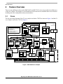
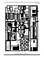
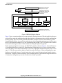
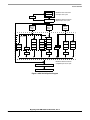
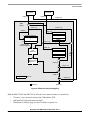
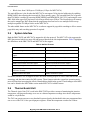
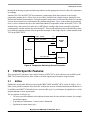
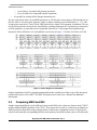
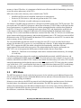
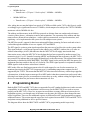
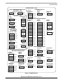
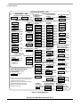
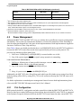
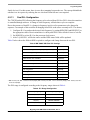
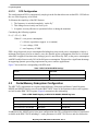
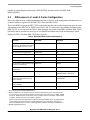
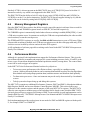
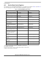
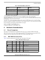
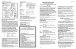
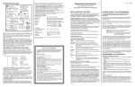
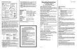
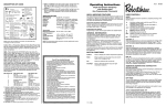
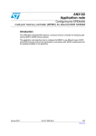
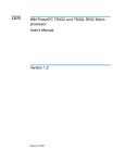
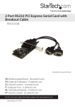
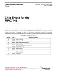
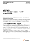
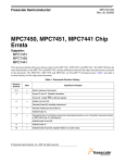
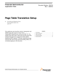
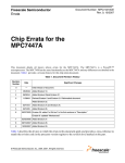
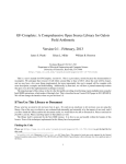
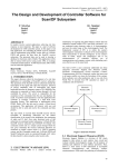
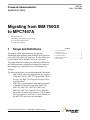
Freescale Semiconductor
Application Note
AN2797
Rev. 2, 06/2005
Migrating from IBM 750GX
to MPC7447A
by
1
Douglas Hamilton
Networking & Computing Systems Group
Freescale Semiconductor, Inc.
East Kilbride, Scotland
Scope and Definitions
The purpose of this application note is to provide
information about migrating from the IBM 750GX processor
to the MPC7447A PowerPC processor. The key differences
between IBM 750GX and MPC7447A are also noted.
This application note examines the architectural differences
and features that have changed and explains the impact of
these changes on a migration in terms of hardware and
software.
The following references are used throughout this document:
• IBM 750GX, which also applies to the G3 complex
of the MPC750/740, MPC755/745 and IBM 750GX
devices. Any IBM 750GX-specific features will be
explicitly stated.
• MPC7447A, which applies, unless otherwise stated
to the MPC7450 family of products: MPC7450,
MPC7451, MPC7441, MPC7455, MPC7445,
MPC7457, MPC7447, and MPC7447A. Since this
document is to aid the migration from 750GX which
does not support L3 cache, the L3 cache features of
the MPC745x devices are not mentioned.
© Freescale Semiconductor, Inc., 2004, 2005. All rights reserved.
1.
2.
3.
4.
5.
6.
Contents
Scope and Definitions . . . . . . . . . . . . . . . . . . . . . . . . . 1
Feature Overview . . . . . . . . . . . . . . . . . . . . . . . . . . . . 2
7447A Specific Features . . . . . . . . . . . . . . . . . . . . . . 11
Programming Model . . . . . . . . . . . . . . . . . . . . . . . . . 14
Hardware Considerations . . . . . . . . . . . . . . . . . . . . . 25
Revision History . . . . . . . . . . . . . . . . . . . . . . . . . . . . 28
Feature Overview
2
Feature Overview
There are many differences between the IBM 750GX and MPC7447A devices beyond the clear differences
of the core complex. This chapter covers the differences between the cores and then other areas of interest
including the cache configuration and system interfaces.
2.1
Cores
The key processing elements of the G3 core complex used in the 750GX are shown in Figure 1 and the G4
core complex used in the 7447A in Figure 2.
Instruction Unit
Additional Features
• Time Base Counter/Decrementer
• Clock Multiplier
• JTAG/COP Interface
• Thermal/Power Management
• Performance Monitor
Integer Unit 1
Integer Unit 2
+x÷
+
Reservation Station
Tags
32-Kbyte
I Cache
64-Bit
(2 Instructions)
System Register
Unit
Reservation Station
(2 Entry)
GPR File
Rename Buffers
(6)
32-Bit
Load/Store Unit
Reservation Station
FPR File
64-Bit
Rename Buffers
(6)
64-Bit
+
(EA Calculation)
CR
Floating-Point
Unit
+x÷
Store Queue
FPSCR
FPSCR
32-Bit
PA
Reorder Buffer
(6 Entry)
IBAT
Array
ITLB
32-Bit
Completion Unit
SRs
(Shadow)
BHT
Dispatch Unit
Reservation Station
Instruction MMU
CTR
LR
BTIC
64 Entry
Instruction Queue
(6 Word)
2 Instructions
Reservation Station
128-Bit
(4 Instructions)
Branch Processing
Unit
Fetcher
Data MMU
SRs
(Original)
DTLB
DBAT
Array
EA
64-Bit
60x Bus Interface Unit
Instruction Fetch Queue
L1 Castout Queue
Tags
32-Kbyte
D Cache
Data Load Queue
64-Bit
L2 Controller
L2CR
L2 Tags
32-Bit Address Bus
64-Bit Data Bus
17-Bit L2 Address Bus
64-Bit L2 Data Bus
Figure 1. IBM 750GX Core Complex
Migrating from IBM 750GX to MPC7447A, Rev. 2
2
Freescale Semiconductor
Freescale Semiconductor
Completes up
to three
instructions
per clock
96-Bit (3 Instructions)
Vector
Integer
Unit 2
128-Bit
Dispatch
Unit
+++
x÷
32-Bit
Integer
Integer
Integer
Unit
122
Unit
Unit
(3)
Integer
Unit 2
Bus Accumulator
Line Block 0/1
Tags Status
Notes: 1. The L3 cache interface is not implemented on the MPC7445.
2. The Castout Queue and Push Queue share resources such for a combined total of 10 entries.
The Castout Queue itself is limited to 9 entries, ensuring 1 entry will be available for a push.
Completed
Stores
External SRAM
(1 0r 2 Mbytes)
64-Bit Data
(8-Bit Parity)
L3CR
L3 Cache Controller1
32-Bit
L1 Push
Finished
Stores
EA
FPR File
Tags
64-Bit
FPSCR
+ x÷
FloatingPoint Unit
Reservation
Stations (2)
36-Bit
Address Bus
64-Bit
Data Bus
Bus Accumulator
Bus Store Queue
Castout
Queue (9) /
Push
Queue (10)2
System Bus Interface
64-Bit
32-Kbyte
I Cache
32-Kbyte
D Cache
Tags
128-Bit (4 Instructions)
16 Rename
Buffers
PA
Load
Queue (11)
Load Miss
L1 Castout
GPR File
16 Rename
Buffers
+ (EA Calculation)
Load/Store Unit
Reservation
Stations (2-Entry)
DBAT Array
128-Entry
DTLB
Data MMU
SRs
(Original)
Vector Touch Engine
18-Bit Address
(19-Bit Address in MPC7447, MPC7457, and MPC7447A)
L2 Store Queue (L2SQ)
Snoop Push/
L1 Castouts
Interventions
(4)
Line Block 0 (32-Byte)
Block 1 (32-Byte)
Tags Status
Status
(512-Kbyte in MPC7447, MPC7457, and MPC7447A)
32-Bit
128-Entry
ITLB
IBAT Array
SRs
(Shadow)
Instruction MMU
Vector
Touch
Queue
FPR Issue
(2-Entry/1-Issue)
Instruction Queue
(12-Word)
Reservation
Reservation
Reservation
Station
Station
Station
256-Kbyte Unified L2 Cache Controller
128-Bit
Vector
FPU
L2 Prefetch (3)
L1 Service
Queues
Vector
Integer
Unit 1
Instruction Fetch (2)
Cacheable Store Request(1)
L1 Load Miss (5)
L1 Load Queue (LLQ)
L1 Store Queue
(LSQ)
Memory Subsystem
Vector
Permute
Unit
VR File
16 Rename
Buffers
Reservation
Stations (2)
LR
BHT (2048-Entry)
VR Issue
(4-Entry/2-Issue)
CTR
BTIC (128-Entry)
Fetcher
GPR Issue
(6-Entry/3-Issue)
Instruction Unit
Branch Processing Unit
Reservation Reservation Reservation Reservation
Station
Station
Station
Station
Completion Queue
(16-Entry)
Completion Unit
• Time Base Counter/Decrementer
• Clock Multiplier
• JTAG/COP Interface
• Thermal/Power Management
• Performance Monitor
Additional Features
Feature Overview
Figure 2. MPC 7447A
Migrating from IBM 750GX to MPC7447A, Rev. 2
3
Feature Overview
2.1.1
Integer Units
Fixed unit 1 (FXU1) and Fixed unit 2 (FXU2) are the complex and simple integer units respectively. The
multiply and divide instructions of FXU1 are multi-cycle, while all other operations are completed in a
single cycle. Both of the integer units operate on 32 32-bit registers. Table 1 shows the operations that each
fixed unit can perform. Each unit consists of three parts, an adder/comparator, logical and a shift/rotate
unit. In addition to these standard units, FXU1 also has a multiply/divide unit.
Table 1. FXU Operations
Operation
FXU1
FXU2
Add, shift, logical functions
Yes
Yes
Multiply/divide
Yes
No
Like the IBM 750GX, the MPC7447A has one complex integer unit with the same functionality as FXU1.
However, it has three simple integer units like FXU2, instead of one. A good compiler can take advantage
of these three simple integer units when presented with a combination of instructions that have multi-cycle
latencies. Such a combination would tie up two of the integer units, allowing the remaining units to start
executing. Thus stalling would be prevented. In addition, the MPC7447A has 16 general purpose registers
(GPR) rename buffers to support the 16-entry completion queue, as compared to the six-entry completion
queue for the IBM 750GX. The floating-point can also source rename buffers as a source operand without
waiting for the value to be committed and retrieved from a GPR.
2.1.2
Floating-Point Units
The IBM 750GX floating-point unit has 32 64-bit registers for single-precision and double-precision
IEEE-754 standards. Different operations have various latencies associated with them due to the 3 stage
pipeline with multiply, add and normalize stages. The latency/throughput varies from 3/1 clock cycles for
single multiply-add, increasing to 4/1 clocks for double multiply and double multiply-add since two cycles
are required in the multiply unit.
The MPC7447A floating-point unit meets the same standards for IEEE-754 precision and, in addition, has
an increased pipeline depth of five stages to allow even double precision calculations to have a one-cycle
throughput. Although the latency is increased, the overall throughput is better for the majority of
double-precision calculations. The floating-point can also source rename buffers as a source operand
without waiting for the value to be committed and retrieved from a fixed point register (FPR).
2.1.3
Instruction Queues
The instruction queue in the IBM 750GX can hold up to six instructions. While the instruction queue depth
allows, the instruction fetcher retrieves up to the four instructions maximum per clock. Two instructions
can be dispatched simultaneously to fixed or floating point units, the branch processing unit and load/store
unit[punctuation] to execute in a four-stage pipeline containing fetch, dispatch, execute, and complete
stages.
Migrating from IBM 750GX to MPC7447A, Rev. 2
4
Freescale Semiconductor
Feature Overview
The MPC7447A offers a twelve-slot instruction queue with a maximum of four fetches per cycle and can
dispatch up to three instructions per cycle to any of the eleven instruction units: the branch processing unit,
the four integer units, the floating-point unit, the four 128-bit (AltiVec) vector units, or the load/store unit.
2.1.4
Branch Processing Unit
The branch processing unit found in the IBM 750GX can process one branch while resolving two
speculative branches per cycle. It uses a 512-deep branch history table (BHT) for dynamic branch
prediction to produce four possible outcomes (not taken, strongly not taken, taken, strongly taken) and
incorporates a 64-entry branch target instruction cache (BTIC) to reduce branch delay slots by supplying
the next instruction(s) from this cache for a particular branch target address, rather than from the
instruction cache, preventing a 1-clock-cycle penalty.
In contrast, the MPC7447A processes one branch per cycle like the IBM 750GX but can resolve three
speculative branches per cycle. The increased BHT with 2048 entries offers the same four prediction states
but with the advantage of a larger size. In addition, the BHT can be cleared to weakly not taken, using
HID0[BHTCLR]. The BTIC is twice the size of the IBM 750GX, providing 128 entries arranged as 32 sets
using a 4-way set-associative arrangement.
2.1.5
Completion Unit
The completion unit works in the IBM 750GX with the dispatch unit so that it can track dispatched
instructions and retire them to the completion queue in order. In following with the dispatch unit, two
instructions can be retired per clock cycles cycle, providing that there are slots available in the completion
queue. When the instruction is removed from the queue, the rename buffers must have been freed and any
results written to processor registers such as GPRs, FPRs, link register (LR), and counter (CTR).
For the MPC7447A, due to deeper pipelines, we can have up to sixteen instructions at some stage of
pipeline processing and retire a maximum of three instructions per clock to one of the sixteen completion
queue slots.
2.2
Pipeline Comparison
The difference in pipeline depths between the IBM 750GX and MPC7447A is significant. With the IBM
750GX, the minimum depth has been kept to a rather short four stages of instruction; fetch,
dispatch/decode, execute, and complete. Write back is included in the complete stage. The pipeline
diagram for the IBM 750GX is shown in Figure 3.
Migrating from IBM 750GX to MPC7447A, Rev. 2
Freescale Semiconductor
5
Feature Overview
–
Fetch
Maximum 4-instruction
fetch per clock cycle
Decode/Dispatch
Maximum 4-instruction
dispatch per clock cycle
(Includes one branch
instruction)
BPU
Execute Stage
FPU1
FPU2
SRU
FPU3
LSU1
IU1
Complete (Write-Back)
LSU2
IU2
Maximum 2-instruction
completion per clock cycle
Figure 3. IBM750GX Pipeline Diagram
Figure 3 shows a maximum depth of six stages using the floating-point unit. If branch prediction does not
work well for a particular application, having a short pipeline is advantageous due to a fairly small pipeline
flushing penalty. However, branch prediction and modern compilers can, more often than not, prevent
frequent pipeline flushes. As a result, the completion rate of two instruction retirements per clock becomes
more of a performance bottleneck. It is also worth noting that the IBM 750GX will not be able to sustain
clock rates of much greater than 1.1GHz without increasing the depth of the pipeline.
With a minimum depth of seven stages, the MPC7447A pipeline, shown in Figure 4, boasts efficient use
of its additional hardware resources by dispatching three instructions per cycle to its execution units as
well as the ability to retire three instructions per cycle. Due to the higher maximum frequency of the 7447A
(up to 1.5GHz) the extra pipeline depth is required to make efficient use of faster running pipeline stage
hardware, reducing the latency of certain instructions, such as many floating point and complex integer
instructions. Compilers can take advantage of the extended pipeline to ensure that the target maximum of
16 instructions in flight at any one time is achieved as closely as possible.
Migrating from IBM 750GX to MPC7447A, Rev. 2
6
Freescale Semiconductor
Feature Overview
Fetch1
Fetch2
Maximum four-instruction
fetch per clock cycle
BPU
Decode/Dispatch
Maximum three-instruction
dispatch per clock cycle
GPR Issue
Queue
(GIQ)
FPR Issue
Queue
(FIQ)
VR Issue
Queue
(VIQ)
Execute Stage
AltiVec Units
FPU-E0
VPU-E0
VPU-E1
VIU1
VIU2-E0
VFPU-E0
FPU-E1
VIU2-E1
VFPU-E1
FPU-E2
IU2-E0
LSU-E0
VIU2-E2
VFPU-E2
FPU-E3
IU2-E1
LSU-E1
VIU2-E3
VFPU-E3
FPU-E4
IU2-E2
LSU-E2
Finish
IU1
Finish
Complete
Finish
Maximum three-instruction
completion per clock cycle
Write-Back
Figure 4. MPC7447A Pipeline Diagram
Migrating from IBM 750GX to MPC7447A, Rev. 2
Freescale Semiconductor
7
Feature Overview
2.3
L1 and L2 Cache
Table 2 summarizes the differences if L1 and L2 cache configuration.
Table 2. L1 and L2 Cache Configurations
Cache Description
L1
L2
2.4
IBM 750GX
MPC7447A
Size, configuration
32 Kbyte Instruction, 32 Kbyte Data 32 Kbyte Instruction, 32 Kbyte Data
8-way set associative
8-way set associative
Memory Coherency
MEI (Data only)
MESI (Data only)
Locking
Completely
By way
Replacement policy
Pseudo-least-recently used (PLRU) Pseudo-least-recently used (PLRU)
Per page/block write configuration
Write-back or write-through (Data)
Write-back or write-through (Data)
Size, configuration
1MB, 4-way set associative
Two 32 byte blocks/line
512KB, 8-way set associative (7447A)
1MB, 8-way set associative (7448)
Two 32 byte blocks/line
Memory Coherency
MEI
MESI
Locking
By way
Completely
Replacement policy
Pseudo-least-recently used (PLRU) 3 bit counter or pseudo random
Parity
8 bits/64 bytes on tags
8 bits/64 bytes on tags and data
MMU
Figure 5 shows the standard PowerPC MMU translation method. The presence of translation lookaside
buffers (TLB) and page table search logic is optional although both implementations incorporate them.
Migrating from IBM 750GX to MPC7447A, Rev. 2
8
Freescale Semiconductor
Feature Overview
Data
Accesses
EA[0–19]
Instruction
Accesses
EA[0–19]
EA[20–31]
MMU
(32-Bit)
X
EA[15–19]
EA[4–19]
EA[0–3]
EA[0–14]
0 Segment Registers
•
•
•
IBAT0U
IBAT0L
•
•
IBAT3U
IBAT3L
EA[15–19]
15
X
Upper 24-Bits
of Virtual Address
EA[0–14]
On-Chip
TLBs
(Optional)
Page Table
Search Logic
(Optional)
DBAT0U
DBAT0L
•
•
DBAT3U
DBAT3L
BAT
Hit
X
PA[0–14]
PA[15–19]
X
PA[0–19]
SDR1
SPR 25
PA[20–31]
Optional
PA[0–31]
Figure 5. Effective to Physical Mapping
Both the IBM 750GX and MPC7447A offer the same common features as seen below,
• 128 entry, 2-way associative instruction TLB and data TLB
• eight data BAT and eight instruction BAT
• Translation for 4 Kbyte page size and 256 Mbyte segment size
Migrating from IBM 750GX to MPC7447A, Rev. 2
Freescale Semiconductor
9
Feature Overview
•
Block sizes from 128 Kbyte to 256 Mbyte (4 Gbyte for MPC7447A)
The main difference is the fact that the MPC7447A can support 36-bit physical addressing by enabling
HID0[XAEN], thus allowing the increased 64 Gbyte memory space. The extended block size of greater
than 256 Mbyte is enabled by asserting HID0[XBSEN] and HID0[HIGH_BAT_EN], and using the extra
XBL field in the upper BAT registers to select larger blocks up to 4Gbyte. The increased area of memory
that can be mapped per BAT means that the programmer does not have to use multiple BATs to map
multiple sequential 256 Mbyte blocks on the MPC7447A.
The other added feature on the MPC7447A is software support for page table searching to offer a custom
page table entry and searching operation if required.
2.5
System Interface
Both the IBM 750GX and MPC7447A support the 60x bus protocol. The MPC7447A also supports the
MPX bus protocol which is a more efficient protocol based on the 60x implementation. Table 3 highlights
the differences in the IBM 750GX and MPC7447A 60x support.
Table 3. 60x Bus Features
IBM 750GX 60x Features
MPC7447A 60x Features
32 bit addressing with 4 bits odd parity
36 bit addressing with 5 bits odd parity
64 bit data bus with 8 bits odd parity, 32 bit data bus
support
64 bit data bus with 8 bits odd parity
Three state MEI cache coherency protocol
Four state MESI cache coherency protocol
L1 and L2 snooping support for cache coherency
L1 and L2 snooping support for cache coherency
Address-only broadcast instruction support
Address-only broadcast instruction support
Address pipelining
Address pipelining
Support for up to 5 outstanding transactions (one
instruction, four data)
Support for up to 16 outstanding transactions
200Mhz maximum bus speed
167Mhz maximum bus speed
In addition, the MPC7447A supports an MPX bus mode offering of up to 16 out-of-order transactions, data
streaming, and data intervention for MP systems. These features make the system bus operation much
more efficient, thus increasing the effective bandwidth available in the system. The advantages of the MPX
bus can be found in the MPX Mode section under MPC7447A Added Features.
2.6
Thermal Assist Unit
The Thermal Assist Unit (TAU) used in the IBM 750GX provides a means of monitoring the junction
temperature, offering an advantage over case or cabinet temperature readings since the die temperature
would be very different.
The TAU can operate on a one or two threshold system whereby the threshold values are programmed into
one or two of the TAU’s four special purpose registers. When the temperature reaches one of these
Migrating from IBM 750GX to MPC7447A, Rev. 2
10
Freescale Semiconductor
7447A Specific Features
thresholds an interrupt is generated allowing software to take appropriate action to reduce the temperature
accordingly.
Instead of the TAU the MPC7447A incorporates a temperature diode that connects to an external
temperature monitor device. These devices are widely available from vendors such as Analog Devices,
Maxim and National Semiconductor. Using the negative temperature coefficient of the diode at a constant
current, the monitor device can determine the junction temperature. Figure 6 shows how the monitoring
device can be connected directly to the anode and cathode of temperature diode on the MPC7447A. The
monitor chip is also connected via the 60x or MPX bus to a bridge chip/system controller which then
communicates with the monitor chip itself using I2C. This second connection allows thresholding values
to be defined so that the monitor chip can generate interrupts via the bridge chip in a similar manner to the
TAU in the IBM 750GX.
TEMP_ANODE
D+
TEMP_CATHODE
D–
Monitor
Chip
ALERT
I2C
MPC7447A
IRQ
60x / MPX Bus
Bridgechip
INT
Figure 6. Temperature Monitoring Device Connection
3
7447A Specific Features
This section briefly introduces some major features of MPC7447A devices that are not available on the
IBM 750GX and explains how these features can offer significant performance improvements.
3.1
AltiVec
Perhaps the most notable difference between the IBM 750GX and MPC7447A is that of AltiVec. It is a
short vector parallel extension of the PowerPC architecture in terms of both instructions and hardware. It
is available on all MPC7450 family devices and can offer up to 11x performance on significant vs. scalar
implementations of some applications.
The key features of AltiVec are:
• 162 new powerful arithmetic and conditional instructions for intra and inter-element, for example
parallelism support
• 4 operands per instructions, 3 sources and 1 destination
• Pipelined execution units to give
Migrating from IBM 750GX to MPC7447A, Rev. 2
Freescale Semiconductor
11
7447A Specific Features
•
— 1 cycle latency for simple and permute operations
— 3-4 cycle latency for compound/complex operations
No penalty for issuing AltiVec/Integer instruction mix
The new instructions allow vector/SIMD operations on 128-bit wide vector registers (VR) through any of
the four Altivec execution units: permute, simple, complex, and float, each of which have 2-, 1-, 4- and
4-stage pipes respectively. These 128-bit VRS can be used as single 128-bit quantity. In addition, VRs can
also be used to provide varying levels of parallelism, yielding a maximum of 16 operations per instruction
on 8-bit quantities, or to put into a more comparable format four 32-bit integer-based operations per
instruction. These different levels of parallelism can be seen in Figure 7, 16x8 bit, 8x16 bit or 4x32 bit.
Figure 7. AltiVec Degrees of Parallelism
Further explanation of AltiVec implementation and benefits would be out of the scope of this document
and therefore please refer to MPC7450 RISC Microprocessor Family User’s Manual for additional
information.
3.2
Comparing MESI and MEI
Another important difference is the difference between the MEI cache coherency features on the 750GX
and the enhanced MESI capability of the 7447A. These protocols are used as a coherency mechanism in
SMP (Symmetric Multi-Processing) configurations to indicate the relationship between 32-byte blocks
stored in cache and their corresponding blocks in main memory. In an SMP system, some or all of the main
Migrating from IBM 750GX to MPC7447A, Rev. 2
12
Freescale Semiconductor
7447A Specific Features
memory is shared. Therefore, it is important to find the most efficient method of maintaining coherency
across the caches and memory of the CPUs.
MEI refers to the cache coherency states available in the 750GX:
• Modified (M) This block is modified with respect to main memory
• Exclusive (E) This block is valid and only present in this CPU’s cache
• Invalid (I) This block is invalid with respect to main memory
An example of an MEI protocol operation is a dual processor SMP system using 750GX processors. The
processors and CPU1 and CPU2 operate on a shared area of memory. If CPU1 loads a cache line from this
area of main memory it is marked as Exclusive with the assumption that the cache has been flushed on
both CPUs. If, however, CPU2 snooped the read request from CPU1 and already had a modified in its
cache, then it would have changed its MEI status to Invalid and pushed the block into main memory
causing CPU1 to wait for and then read the latest version of the data. Then, if CPU2 tries to read the data
again, it must read it from main memory; and to make the situation worse, CPU1 may have since modified
the data in its cache. If CPU1 did modify the data then CPU2 would have to wait for CPU1 to write its data
back to memory for the CPU2 to access.
The extra bandwidth used and time wasted in waiting for each CPU to write its cache block back to
memory for the other CPU to access is a very inefficient use of the bus. To help combat this problem the
MPC7447A supports the MPX bus which extends the 60x functionality with some efficiency
improvements as discussed in the next section. The main method used to improve performance on
MPC7447A was to incorporate the MESI protocol which includes the new shared state:
• Shared (S) - This block exists in multiple caches and is consistent with main memory, for example,
it is read only
The addition of this state reduces the wasted time and bandwidth associated with MEI coherency and
requires an additional 60x/MPX signal called SHD. If we look at the previous example it is easy to see the
benefits of the MESI over MEI. If CPU1 tried to read a block of main memory to its cache, CPU2 would
snoop the transaction as before but this time assert the SHD signal to tell CPU1 that it also has a cached
copy of this block. CPU1 would load the block into it’s cache with shared status and CPU2 would change
it’s cache entry to shared from exclusive, allowing both CPUs to access the data quickly from cache
provided that the data is only.
3.3
MPX Mode
The MPX bus protocol is based on the 60x bus protocol. It also includes several additional features that
allow it to provide higher memory bandwidth than the 60x bus and more efficient utilization of the system
bus in a multiprocessing environment.
Memory accesses that use the MPX bus protocol are divided into address and data tenures. Each tenure
has three phases: bus arbitration, transfer, and termination. The MPX bus protocol also supports
address-only transactions. Note that address and data tenures can overlap. One of the key differences to
the 60x bus is that the MPX does not require an idle cycle between tenures. To illustrate the importance of
this difference, consider the following example:
Migrating from IBM 750GX to MPC7447A, Rev. 2
Freescale Semiconductor
13
Programming Model
•
100Mhz 60x bus:
— Transfer rate = (32 bytes / 5 clock cycles) * 100MHz = 640MB/s
•
100Mhz MPX bus:
— Transfer rate = (32 bytes / 4 clock cycles) * 100MHz = 800MB/s
Also, taking into account the higher bus speeds of 167MHz available on the 7447A, this figure is scaled
accordingly to give significant increase to 1336MB/s, which compares favorably to the 750GX 1280MB/s
maximum with its 200MHz 60x bus.
The address and data tenures in the MPX bus protocol are distinct from one another and each tenure
consists of three phases—arbitration, transfer, and termination. The separation of the address and data
tenures allows advanced bus techniques—such as split-bus transactions, enveloped transactions, and
pipelining—to be implemented at the system level in multiprocessor systems.
The MPX bus mode’s support for data intervention and full data streaming for burst reads and writes is
realized through the addition of two new signals—HIT and DRDY.
The HIT signal is a point-to-point signal output from the processor or local bus slave to the system arbiter.
This signal indicates a valid snoop response in the address retry (ARTRY) window (the cycle after an
address acknowledge (AACK) that indicates that the MPC7447A will supply intervention data).
Intervention occurs when the MPC7447A has the data that has been requested by another master’s bus
transaction in its L1 or L2. Instead of asserting ARTRY and flushing the data to memory, the MPC7447A
may assert HIT to indicate that it can supply the data directly to the other master. This external intervention
functionality is disabled by MSSCR0[EIDIS]. The DRDY signal is also used by the MPX bus protocol to
implement data intervention in the case of a cache hit. The SHD1 signal operates in conjunction with the
SHD0 signal to indicate that a cached item is shared.
MPX mode offers one final improvement to the 60x with support for out of order transactions. As
mentioned previously the MPC7447A supports up to 16 outstanding transactions compared to the 5
supported by the 750GX. This means that the MPC7447A has increased efficiency with its deeper pipeline
of transactions. A further improvement specific to MPX mode is that these transactions can be out of order,
allowing lower latency devices to return data as soon as they are ready, without waiting for higher latency
devices to return data first just because their transaction was first.
4
Programming Model
Both the IBM 750GX and MPC7447A have to support the PowerPC standard architecture in order to retain
compatibility in user mode. Recompilation is not necessary for the IBM 750GX user code to execute
properly on the MPC7447A. However, in supervisor mode there are many differences between device
dependent registers; even though some of the names are the same, the fields are often changed in name
and/or bit position. There are also additional registers in different PowerPC implementations to support
additional features. This section maps the supervisor level registers between IBM 750GX and MPC7447A
and points out any additional or device specific features.
The diagrams below show the IBM 750GX and MPC7447A programming model respectively.
Migrating from IBM 750GX to MPC7447A, Rev. 2
14
Freescale Semiconductor
Programming Model
SUPERVISOR MODEL—OEA
Configuration Registers
USER MODEL—VEA
Time Base Facility (For Reading)
TBL
TBR 268
TBU
TBR 269
USER MODEL—UISA
General-Purpose
Registers
Count
Register
CTR
GPR0
SPR 9
XER
SPR 1
SPR 937
UPMC2
SPR 938
UPMC3
SPR 941
UPMC4
SPR 942
SPR 939
Monitor Control1
UMMCR0
SPR 936
UMMCR1
SPR 940
PMC1
SPR 953
PMC2
SPR 954
PMC3
SPR 957
PMC4
SPR 958
SPR 1016
Data BAT
Registers
IBAT0U
SPR 528
THRM1
SPR 1020
THRM2
SPR 1021
THRM3
SPR 1022
THRM4
SPR 920
Segment
Registers
DBAT0U
SPR 536
SR0
SR1
DBAT0L
SPR 537
DBAT1U
SPR 538
Floating-Point
Registers
IBAT1L
SPR 531
DBAT1L
SPR 539
IBAT2U
SPR 532
DBAT2U
SPR 540
FPR0
IBAT2L
SPR 533
DBAT2L
SPR 541
FPR1
IBAT3U
SPR 534
DBAT3U
SPR 542
IBAT3L
SPR 535
DBAT3L
SPR 543
IBAT4U
SPR 560
DBAT4U
SPR 568
IBAT4L
SPR 561
DBAT4L
SPR 569
IBAT5U
SPR 562
DBAT5U
SPR 570
IBAT5L
SPR 563
DBAT5L
SPR 571
IBAT6U
SPR 564
DBAT6U
SPR 572
IBAT6L
SPR 565
DBAT6L
SPR 573
IBAT7U
SPR 566
DBAT7U
SPR 574
IBAT7L
SPR 567
DBAT7L
SPR 575
FPR31
Condition
Register
CR
Floating-Point
Status and
Control Register
FPSCR
Sampled
Instruction
Address1
SPRG0
SPR 272
SPRG1
SPR 273
SPRG2
SPR 274
SPRG3
SPR 275
SPR 955
Monitor Control1
SDR1
SDR1
SPR 25
Data Address
Register
DAR
SPR 952
External Access
Register
MMCR1
SPR 956
EAR
Instruction Cache
Throttling Control
Register1
SRR1
DSISR
DSISR
SPR 27
SPR 18
Time Base
(For Writing)
SPR 282
Data Address
Breakpoint Register
SPR 1019
SPR 19
Save and Restore
Registers
SPR 1010
SRR0
SPR 26
Miscellaneous Registers
MMCR0
ICTC
SR15
Exception Handling Registers
SPRGs
SIA
MSR
Memory Management Registers
Power/Thermal Management Registers
Thermal Assist
Unit Registers1
SPR 287
SPR 530
Performance Monitor Registers
Performance
Counters1
HID2
PVR
SPR 529
Sampled Instruction
Address1
USIA
SPR 1009
IBAT0L
Performance Counters1
UPMC1
SPR 1008
HID1
IBAT1U
SPR 8
Performance
Monitor Registers
(For Reading)
HID0
Machine State
Register
GPR31
Link Register
LR
Processor
Version
Register
Instruction BAT
Registers
GPR1
XER
Hardware
Implementation
Registers1
DABR
Decrementer
DEC
TBL
SPR 284
TBU
SPR 285
L2 Control
Register1, 2
SPR 1013
L2CR
SPR 22
Instruction Address
Breakpoint Register1
SPR 1017
IABR
Figure 8. 750GX Registers
Migrating from IBM 750GX to MPC7447A, Rev. 2
Freescale Semiconductor
15
Programming Model
SUPERVISOR MODEL—OEA
Configuration Registers
USER MODEL—VEA
Time Base Facility (For Reading)
TBR 268
TBL
TBR 269
TBU
USER MODEL—UISA
General-Purpose
Count Register
Registers
SPR 9
CTR
GPR0
XER
GPR1
SPR 1
XER
Link Register
SPR 8
LR
GPR31
Performance Monitor
Registers
Floating-Point
Performance Counters1
Registers
SPR 937
UPMC1
FPR0
SPR 938
UPMC2
FPR1
SPR 941
UPMC3
SPR 942
UPMC4
UPMC5
SPR 929
FPR31
UPMC6
SPR 930
Condition
Sampled Instruction
Register
Address1
CR
SPR 939
USIAR
Monitor Control1
Floating-Point
Status and
UMMCR0 SPR 936
Control Register
UMMCR1 SPR 940
FPSCR
UMMCR2 SPR 928
AltiVec Registers
Vector Save/Restore
Register 3
VRSAVE SPR 256
Vector Status and3
Control Register
Vector Registers 3
VR0
VR1
VR31
VSCR
Thermal Management Register
Instruction Cache Throttling
Control Register 1
ICTC
1
SPR 1019
MPC7445-, MPC7447-, MPC7455-, and MPC7457-specific
register may not be supported on other processors that
implement the PowerPC architecture.
2
Register defined as optional in the PowerPC architecture.
3
Register defined by the AltiVec technology.
4
MPC7455- and MPC7457-specific register.
5
MPC7457-specific register.
Machine State Register
Hardware
Processor Version
Implementation
MSR
Register
1
Registers
PVR
SPR 287 Processor ID Register 2
SPR 1008
HID0
SPR 1023
PIR
SPR 1009
HID1
Memory Management Registers
Instruction BAT
Registers
SPR
IBAT0U
SPR
IBAT0L
SPR
IBAT1U
SPR
IBAT1L
SPR
IBAT2U
SPR
IBAT2L
SPR
IBAT3U
SPR
IBAT3L
IBAT4U 1 SPR
IBAT4L 1 SPR
IBAT5U 1 SPR
IBAT5L 1 SPR
IBAT6U 1 SPR
IBAT6L 1 SPR
IBAT7U 1 SPR
IBAT7L 1 SPR
528
529
530
531
532
533
534
535
560
561
562
563
564
565
566
567
Data BAT
Registers
DBAT0U
DBAT0L
DBAT1U
DBAT1L
DBAT2U
DBAT2L
DBAT3U
DBAT3L
DBAT4U 1
DBAT4L 1
DBAT5U 1
DBAT5L 1
DBAT6U 1
DBAT6L 1
DBAT7U 1
DBAT7L 1
SPR
SPR
SPR
SPR
SPR
SPR
SPR
SPR
SPR
SPR
SPR
SPR
SPR
SPR
SPR
SPR
Segment Registers
SR0
SR1
536
537
538
SR15
539
540 PTE High/Low
541 Registers 1
542
PTEHI
SPR 981
543
PTELO
SPR 982
568
TLB Miss Register1
569
TLBMISS SPR 980
570
571 SDR1
572
SPR 25
SDR1
573
Cache/Memory
574
Subsystem Registers
575
Memory Subsystem
Exception Handling Registers
Status Control Registers 1
SPRGs
Data Address
MSSCR0 SPR 1014
Register
SPRG0 SPR 272
MSSSR0 SPR 1015
SPR 19
DAR
SPRG1 SPR 273
Load/Store
DSISR
SPRG2 SPR 274
Control Register 1
SPR 18
DSISR
SPRG3 SPR 275
LDSTCR SPR 1016
SPRG4 1 SPR 276
Save and Restore
Instruction Cache/
Registers
SPRG5 1 SPR 277
Interrupt Control Register 1
SPR 26
SRR0
SPRG6 1 SPR 278
SPR 1011
ICTRL
SPR 27
SRR1
SPRG7 1 SPR 279
L2 Cache
Control Register1
Performance Monitor Registers
2
Performance Counters Breakpoint Address
SPR 1017
L2CR
Mask Register1
SPR 953
PMC1
L3 Private Memory
SPR 951 Address Register 4
BAMR
SPR 954
PMC2
SPR 957 Monitor Control
PMC3
L3PM
SPR 983
SPR 958 Registers
PMC4
L3 Cache
SPR 945
MMCR02 SPR 952
PMC5
Control Register 4
2
SPR
956
SPR 946
MMCR1
PMC6
L3CR
SPR 1018
MMCR21 SPR 944
Sampled Instruction
L3 Cache Input
Address Register 2
Timing
SPR 955 L3 Cache Output Hold
SIAR
5
L3ITCR0 4 SPR 984
Control Register
L3ITCR1 5 SPR 1001
L3OHCR SPR 1000
L3ITCR2 5 SPR 1002
L3ITCR3 5 SPR 1003
Miscellaneous Registers
Data Address
Time Base
Instruction Address
(For Writing)
Breakpoint Register 1 Breakpoint Register 2
SPR 1010
SPR 1013
IABR
DABR
TBL SPR 284
External Access Register 2
TBU SPR 285 Decrementer
EAR
SPR 282
SPR 22
DEC
Figure 9. 7447A Registers
Migrating from IBM 750GX to MPC7447A, Rev. 2
16
Freescale Semiconductor
Programming Model
4.1
Differences in HID0 and HID1
Although both the IBM 750GX and MPC7447A have both of these registers defined in their
implementation, the registers are optional to the standard and therefore differences in bit settings between
devices do exist. Table 4 summarizes these differences and shows the mapping of fields between devices.
Table 4. IBM 750GX HID0 to MPC7447A Mapping
Function
IBM 750GX
Enable MCP
HID0[EMCP]
HID1[EMCP]
Disable 60x bus address and data parity
generation
HID0[DBP]
N/A1
Enable 60x bus address parity checking
HID0[EBA]
HID1[EBA]
Enable 60x bus data parity checking
HID0[EBD]
HID1[EBA]
Disable precharge of ARTRY
HID0[PAR]
HID1[PAR]
Doze mode enable
HID0[DOZE]
N/A2
Nap mode enable
HID0[NAP]
HID0[NAP]
HID0[SLEEP]
HID0[SLEEP]
HID0[DPM]
HID0[DPM]
HID0[RISEG]
N/A3
Miss-under-miss enable enable
HID0[MUM]
N/A4
Not a hard reset
HID0[NHR]
HID0[NHR]
Instruction cache enable
HID0[ICE]
HID0[ICE]
Data cache enable
HID0[DCE]
HID0[DCE]
Instruction cache lock
HID0[ILOCK]
HID0[ILOCK]
Data cache lock
HID0[DLOCK]
HID0[DLOCK]
Instruction cache flush invalidate
HID0[ICFI]
HID0[ICFI]
Data cache flush invalidate
HID0[DCFI]
HID0[DCFI]
Speculative data and instruction cache
disable
HID0[SPD]
HID0[SPD]
Enable M bit on bus for instruction fetches
(M from WIM states)
HID0[IFEM]
HID0[23]5
Store gathering enable
HID0[SGE]
HID0[SGE]
Data cache flush assist
HID0[DCFA]
HID0[25]6
BTIC enable
HID0[BTIC]
HID0[BTIC]
Address broadcast enable
HID0[ABE]
HID1[ABE]7
Sleep mode enable enable
Dynamic power management enable
Read instruction segment register
MPC7447A
Migrating from IBM 750GX to MPC7447A, Rev. 2
Freescale Semiconductor
17
Programming Model
Table 4. IBM 750GX HID0 to MPC7447A Mapping (continued)
Function
IBM 750GX
Branch History Table enable
HID0[BHT]
HID0[BHT]
HID0[NOOPTI]
HID0[NOOPTI]
No-op the data cache touch instructions
MPC7447A
1.
Not available in MPC7447A implementation.
Not required on MPC7447A due to processor-system handshake protocol system explained in Power Management.
3
. Not implemented. For test only on the 750GX.
4.
Always enabled in MPC7447A implementation. The IBM 750GX supports 4 outstanding misses (3 data and 1 instruction or 4
data) and the MPC7447A supports 5 outstanding data misses.
5.
Reserved. Used for IFEM in earlier processors but is also used for Extended BAT Block Size Enable.
6.
Reserved. Defined as DCFA on earlier processors.
7. Must be enabled in multiprocessing systems. HID1[SYNCBE] enables address broadcast for sync and eieio instructions.
2.
4.2
Power Management
Although the IBM 750GX and MPC7447A are very similar, there are differences in power management
functionality. This section only mentions the differences. Features like Instruction Cache Throttling to
slow the instruction dispatch rate is the same in both implementations. Both implementations support the
four states: Full Power, Doze, Nap and Sleep.
From Table 4 above you should note that the there is no HID0[DOZE] bit for the MPC7447A and this is
because the MPC7447A enters Doze mode when requested by the processor-system protocol. The
processor can transition to Doze mode from:
1. Full Power, if HID0[NAP] or HID0[SLEEP] is asserted and the core is idle.
2. Nap, if the system negates QACK to signal a snoop operation is outstanding.
It can transition from Doze mode to:
1. Full Power, following one of many possible interrupts: external, SMI interrupt, SRESET,
HRESET, machine check or decrementer interrupt.
2. Nap, if the system asserts QACK with HID0[NAP] set.
or
3. Sleep, if system asserts QACK with HID0[SLEEP] set.
Additionally, the MPC7447A has a Deep Sleep mode which can offer further power savings from Sleep
mode by turning off the PLL by setting PLL_CFG to 0xF and hence allowing the SYSCLK source to be
disabled.
For further explanation on standard power management features between both implementations please
refer to the MPC7450 RISC Microprocessor Family User’s Manual.
4.2.1
PLL Configuration
HID1 primarily holds PLL configuration and other control bits in both the IBM 750GX and MPC7447A.
However, there are a couple of differences as shown below, due to the dual PLL in the 750GX, as compared
to the Dynamic Frequency Selection (DFS) in the MPC7447A (not featured in other current MPC7450
Migrating from IBM 750GX to MPC7447A, Rev. 2
18
Freescale Semiconductor
Programming Model
family devices). For this reason, there is not a direct mapping between the two. The concept behind both
schemes is to save power by reducing the core clock rate when full rate is not required.
4.2.1.1
Dual PLL Configuration
The 750GX has dual PLL allowing the frequency to be selected from PLL0 or PLL1 where the transition
is controlled through software. A change in clock frequency will take three cycles to complete.
Due to the presence of dual PLL, a change in frequency involves a few parameters to be changed in
sequence. An example of this would be in changing from PLL0 as the source currently to PLL1 as shown,
1. Configure PLL1 to produce the desired clock frequency, by setting HID1[PR1] and HID1[PC1] to
the appropriate values. Bear in mind there is a delay until PLL1 locks which we have to wait for.
2. Set HID1[PS] to select PLL1 as the processor clock source.
3. After 3 cycles PLL1 will be the source and the HID1 status fields will be updated.
Table 5 below shows the fields in HID1 required to configure and change between the two PLL.
Table 5. IBM 750GX HID1/Dual PLL Settings
Function
IBM 750GX
PLL external configuration, PLL_CFG[0-4] (Read only)
HID1[PCE]
PLL external range configuration (Read only)
HID1[PRE]
PLL status/selection
HID1[PSTAT1]
Enable external clock, CLKOUT
HID1[ECLK]
Internal clock to output, CLKOUT, selection
HID1[9-11] 1
PLL0 internal configuration select
HID1[PIO]
PLL select
HID1[PS]
PLL0 configuration
HID1[PC0]
PLL0 range select
HID1[PR0]
PLL1 configuration
HID1[PC1]
PLL1 range select
HID1[PR1]
1. 000
- Factory use, 001 - PLL0 core clock (freq/2), 010 - Factory use, 011 – PLL1 core clock (freq/2), 100 - Factory use, 101 Core clock (freq/2)
The PLL range is configured according to the frequency ranges shown in Table 6.
Table 6. PLL Range Configuration
PLL_RNG[0:1]
PLL Frequency Range
00 (default)
600 MHz–900 MHz
01 (fast)
900 MHz–1.0 GHz
10 (slow)
500 MHz–600 MHz
11 (reserved)
Reserved
Migrating from IBM 750GX to MPC7447A, Rev. 2
Freescale Semiconductor
19
Programming Model
4.2.1.2
DFS Configuration
The configuration of DFS is comparatively simple given the fact that it does not use dual PLL. DFS allows
the core clock frequency to be halved.
To illustrate the simplicity of the DFS features:
1. The frequency is switched completely “on the fly”.
2. This change occurs in only one clock cycle.
3. It requires zero any idle time or operations before or during the transition.
Considering the following equation:
P = (C • V2 • f) + PDS
Where:P = core power consumption
C = effective capacitance (approx. as a constant)
V = core voltage, VDD
f = core frequency, fCORE
PDS= deep sleep mode power consumptionExcluding deep sleep mode power consumption, which is a
minimum fixed power cost for an inactive core, the dynamic power consumption of the device is halved
when DFS is applied. Note that static (leakage) power is not affected by DFS, so the power consumption
with DFS enabled is not exactly 50% of the full-power consumption. This provides a significant advantage
in supporting dynamic processing requirements in power sensitive applications.
Figure 7 shows the bits corresponding with DFS mode.
Table 7. MPC7447A HID1/DFS Settings
4.3
Feature
MPC7447A
DFS divide by two enable
HID1[DFS]
PLL configuration, PLL_CFG[0-4] (Read only)
HID1[PC0-PC4]
Cache/Memory Subsystem Configuration
The MPC7447A implements two registers named Memory Subsystem and Status Control Registers,
MSSSR and MSSCR that do not exist in the IBM 750GX. Some of the functions in these extra registers
are held in other IBM 750GX register. Figure 8 summarizes this relationship.
Table 8. IBM 750GX Mapping to MPC7447A MSSSR, MSSCR Registers
Function
IBM 750GX
MPC7447A
Address bus parity error
SRR1[AP]
MSSSR[APE]
Data bus parity error
SRR1[DP]
MSSSR[DPE]
Bus transfer error acknowledge
SRR1[TEA]
MSSSR[TEA]
In addition to this, MSSCR stores some more configuration data. This configuration relates to features not
available in the IBM 750GX including L3 cache parameters for MPC745x devices and also defines the
Migrating from IBM 750GX to MPC7447A, Rev. 2
20
Freescale Semiconductor
Programming Model
number of outstanding bus transactions, MSSCR[DTQ], and intervention for MPX mode,
MSSCR[EIDIS].
4.4
Differences in L1 and L2 Cache Configuration
Due to the differences in each programming model the L1 and L2 cache configuration and status bits are
located in different registers for the MPC7447A from the IBM 750GX.
There is no HID2 register in the MPC7447A so the following table shows which register bits give the same
functionality in the MPC7447A. HID2 is used for L1 and L2 cache parity error settings and status in the
IBM 750GX. As you can see from Table 9, these functions are spread across SSR1 which the IBM 750GX
has but the bits in question are reserved, as well MSSSR and Instruction Cache and Interrupt Control
Register, ICTRL, which the IBM 750GX does not have.
Table 9. IBM 750GX HID2 to MPC7447A Mapping
Function
IBM 750GX
MPC7447A
Disable store under miss
processing. (Permitted outstanding
stores changes from two to one)
HID2[STMUMD]
N/A 1
Force instruction-cache bad parity
HID2[FICBP]
N/A 1
Force instruction-tag bad parity
HID2[FITBP]
N/A 1
Force data-cache bad parity
HID2[FDCBP]
N/A 1
Force data-tag bad parity
HID2[FDTBP]
N/A 1
Force L2-tag bad parity
HID2[FL2TBP]
N/A 1
L1 instruction-cache/instruction-tag HID2[ICPS]
parity error status/mask
SRR1[1]
L1 data-cache/data-tag parity error
status/mask
HID2[DCPS]
SRR1[2]
L2 tag parity error status/mask
HID2[L2PS]
MSSSR[L2TAG] – Tag error
(MSSSR[L2DAT]) – Data error
Enable L1
instruction-cache/instruction-tag
parity checking
HID2[ICPE]
ICTRL[EICE]
(ICTRL[EICP])2
Enable L1 data-cache/data-tag
parity checking
HID2[DCPE]
ICTRL[EDEC]
Enable L2 tag parity checking
HID2[L2PE]
L2CR[L2PE] 3
1.
Not available in MPC7447A implementation.
When the EICP bit is set, the parity of any instructions fetched from the L1 instruction cache
are checked. Any errors found are reported as instruction cache parity errors in SRR1. If EICE
is also set, these instruction cache errors cause a machine check or checkstop. If either EICP
or EICE is cleared, instruction cache parity is ignored.
Note that when parity checking and error reporting are both enabled, errors are reported even
on speculative fetches that are never actually executed. Correct instruction cache parity is
always loaded into the L1 instruction cache regardless of whether checking is enabled or not.
3. Enables tag AND data parity.
2.
Migrating from IBM 750GX to MPC7447A, Rev. 2
Freescale Semiconductor
21
Programming Model
Table 10 shows the mapping of the IBM 750GX’s L2CR to the MPC7447A.
Table 10. IBM 750GX L2CR to MPC7447A Mapping
Function
IBM 750GX
MPC7447A
L2 cache enable
L2CR[L2E]
L2CR[L2E]
L2 double bit checkstop enable
L2CR[CE]
N/A 1
L2 data only
L2CR[DO]
L2CR[DO]
L2 global invalidate
L2CR[GI]
L2CR[L2I]
L2 write through
L2CR[WT]
N/A 1
L2 test support
L2CR[TS]
N/A 1
L2 cache way locking
L2CR[LOCK] 2
L2CR[D0] and L2CR[IO]
Snoop hit in locked line checkstop
enable
L2CR[SHEE]
N/A 1
Snoop hit in locked line error
L2CR[SHEER]
N/A 1
L2 instruction only
L2CR[IO]
L2CR[IO]
L2 global invalidate progress bit
L2CR[IP]
N/A 1
1. Not available in MPC7447A implementation.
2. IBM 750GX still has L2CR[LOCKLO] and L2CR[LOCKHI] for backwards compatibility when it could only lock the bottom two
ways or top two ways.
4.4.1
MPC7450 Extended Capabilities
The MPC7447A also offers the choice of the first or second replacement algorithm, L2CR[L2REP], and
an L2 hardware flush feature, L2CR[L2HWF], which the 750GX does not.
An L2 feature supported on the MPC7447A family but not the 750GX is L2 prefetching. This can offer an
improvement in performance by loading the second block of a cache line after a cache miss on the line.
The idea being that the second block maybe required in the near future even if it is not required right now.
The MPC7447A family takes advantage of this concept, known as spatial locality, using up to 3 hardware
prefetch engines.
The L2 prefetching feature can be enabled by setting the L2 prefetch enable bit in memory configuration
subsystem register, MSSCR0[PFE], providing the L2 cache is enabled and not configured as data or
instruction only.
4.4.2
L1 and L2 Cache Locking
The MPC7447A contains a Load/Store Control Register which configures L1 data cache locking by way.
The LDSTCR is not present in the IBM 750GX because it is not supported. It can be configured on the
MPC7447A using the 8 bits in LDSTCR[DCWL], indicating which way(s) to lock.
Migrating from IBM 750GX to MPC7447A, Rev. 2
22
Freescale Semiconductor
Programming Model
Similarly ICTRL is also not present on the IBM 750GX since its ICTRL[ICWL]is used to lock the L1
instruction cache by way which is not supported in the IBM 750GX.
The IBM 750GX has the ability to lock L2 cache by way using L2CR[LOCK] bits and L2CR[DO] or
L2CR[IO] to set the L2 as data or instruction. The MPC7447A does not support locking by way but the
whole cache can be locked by setting both L2CR[DO] AND L2CR[IO].
4.5
Memory Management Registers
Since the IBM 750GX does not have the ability to resolve page table entries in software it has no need for
PTEHI, PTELO and TLBMISS registers known as SPR 981, 982 and 980 respectively.
The TLBMISS register is automatically loaded when software searching is enabled (HID0[STEN] = 1) and
a TLB miss exception occurs. Its contents are used by the TLB miss exception handlers (the software table
search routines) to start the search process.
The PTEHI and PTELO registers are used by the tlbld and tlbli instructions to create a TLB entry. When
software table searching is enabled, and a TLB miss exception occurs, the bits of the page table entry (PTE)
for this access are located by software and saved in the PTE registers.
A full explanation of software page table searching can be found in the MPC7450 RISC Microprocessor
Family User’s Manual.
4.6
Performance Monitor
Although it is optional, both implementations support the Performance Monitor features. This gives the
user software the ability to monitor and count specific events including processor clocks, L1 and L2 cache
misses, types of instructions dispatched and branch prediction statistics, among others. The count of these
events can be used to trigger an exception.
In the MPC7447A the Performance Monitor has three key objectives:
• To increase system performance with efficient software, especially in a multiprocessing
system—Memory hierarchy behavior can be monitored and studied in order to develop algorithms
that schedule tasks (and perhaps partition them) and that structure and distribute data optimally.
• To characterize processors—Some environments may not be easily characterized by a benchmark
or trace.
• To help system developers bring up and debug their systems.
The MPC7447A contains two additional Performance Counters, PMC5 and PMC6, a Breakpoint Address
Mask Register, BAMR, and an extra Monitor Control Register, MMCR2. This section looks at any
differences in the common registers and the purpose of the extra MPC7447A registers. The MPC7447A
offers the extra registers to monitor more events including AltiVec based events which the IBM 750GX
obviously does not have to support. Full listings of PMC events available in each implementation can be
found in IBM PowerPC 750GX RISC Microprocessor User Manual and MPC7450 RISC Microprocessor
Family’s User Manual.
Each implementation provides read registers in user mode for PMC and MMCR registers with the prefix
U, for example UPMC1 or UMMCR1.
Migrating from IBM 750GX to MPC7447A, Rev. 2
Freescale Semiconductor
23
Programming Model
4.6.1
Monitor Mode Control Registers
The mapping between the MMCR0 and MMCR1 is very similar but not identical. Table 11 and Table 12
shows this mapping for the IBM 750GX MMCR0 and MMCR1 respectively.
Table 11. IBM 750GX MMCR0 to MPC7447A
Function
IBM 750GX
MPC7447A
Disable counting unconditionally
MMCR0[DIS]
MMCR0[FC]
Disable counting while in supervisor MMCR0[DP]
mode
MMCR0[FCS]
Disable counting while in user mode MMCR0[DU]
MMCR0[FCP]
Disable counting while MSR[PM] is MMCR0[DMS]
set
MMCR0[FCM1] 1
Disable counting while MSR[PM] is MMCR0[DMR]
zero
MMCR0[FCM1] 1
Enable performance monitor
interrupt signaling
MMCR0[ENINT]
MMCR0[PMXE]
Disable counting of PMCn when a
performance monitor interrupt is
signalled
MMCR0[DISCOUNT]
MMCR0[FCECE] 2
64 bit time base transition selector
MMCR0[RTCSELECT]
MMCR0[TBSEL]
Enable interrupt when RTCSELECT MMCR0[INTONBITTRANS]
defined bit transitions off/on
MMCR0[TBEE]
Threshold value, 0-63, which can be MMCR0[THRESHOLD]
varied to get to characterize the
events occurring above the
threshold
MMCR0[THRESHOLD]
Enable interrupt due to do PMC1
overflow
MMCR0[PMC1INTCONTROL]
MMCR0[PMC1CE]
Enable interrupts due to PMCn
overflow
MMCR0[PMCINTCONTROL]
MMCR0[PMCnCE] 3
MMCR0[PMCTRIGGER]
Trigger counting of PMC2-4 after
PMC1 overflows or after a interrupt
is signalled
MMCR0[TRIGGER] 4
PMC1 event selector, 128 events
MMCR0[PMC1SELECT]
MMCR0[PMC1SEL]
PMC2 event selector, 64 events
MMCR0[PMC2SELECT]
MMCR0[PMC2SEL]
1. MSR[PM] on the IBM 750GX corresponds to MSR[PMM] on the MPC7447A.
2. For all PMCs, not just PMCn.
3. Enable overflow interrupts on PMC1-4 for IBM 750GX and PMC1-6 for MPC7447A.
4. Trigger counting of PMC2-6 for MPC7447A.
Migrating from IBM 750GX to MPC7447A, Rev. 2
24
Freescale Semiconductor
Hardware Considerations
Table 12. IBM 750GX MMCR1 to MPC7447A
1.
Function
IBM 750GX
MPC7447A
PMC3 event selector, 32 events
MMCR0[PMC3SELECT]
MMCR0[PMC3SEL]
PMC4 event selector, 32 events
MMCR0[PMC4SELECT]
MMCR0[PMC4SEL]
PMC5 event selector, 32 events
N/A 1
MMCR0[PMC5SEL]
PMC6 event selector, 64 events
N/A 1
MMCR0[PMC6SEL]
PMC5 and PMC6 not present in IBM 750GX.
As mentioned previously the MPC7447A also has a MMCR2 register with a one bit field,
MMCR2[THRESHMULT]. This can be used to extend the range of the MMCR0[THRESHOLD] field by
multiplying by 2 if set at 0 or by 32 if set at 1.
The MPC7447A also has a breakpoint address mask register (BAMR) that is used as a mask for debug
purposes to compare to IABR[0:29] when PMC1 is set to monitor event 42. This event monitors for IABR
hits specifically by checking they match BAMR. For example:
Match = ((IABR[0–29] & BAMR[0–29]) ==
(completion_address[0–29] & BAMR[0–29]))
5
5.1
Hardware Considerations
Pin-out Comparison
Since there is no footprint/pin-out compatibility the easiest way to compare the IBM 750GX and
MPC7447A pins is to look at the different pins on the IBM 750GX that do not exist on the MPC7447A
and then to look at the pins present on the MPC7447A but not on the IBM 750GX.
5.1.1
IBM 750GX Uncommon Pins
Table 13 shows the signal name, pin number and a description of the signal.
Table 13. IBM 750GX additional signals
Signal Name
Pin Number
Active
I/O
Description
A1Vdd
Y15
PLL0 supply voltage
A2Vdd
Y16
PLL1 supply voltage
ABB
Y6
AGND
Y14
DBB
U7
Low
I/O
DBDIS
A10
Low
I
Data bus disable
DBWO
A6
Low
I
Data bus write only
Low
I/O
Address bus busy
Ground for PLL
Data bus busy
Migrating from IBM 750GX to MPC7447A, Rev. 2
Freescale Semiconductor
25
Hardware Considerations
Table 13. IBM 750GX additional signals
Signal Name
Pin Number
Active
I/O
DRTRY
W3
Low
I
GBL
W1
Low
I/O
W15, U14
High
I
Specifies PLL range1
Y4
Low
O
Internal reservation coherency bit
W11
Low
I
TLB invalidate synchronize
PLL_RNG
RSRV
TLBISYNC
Description
Data retry
Global signal is required for IBM 750GX snooping
1. As in Table 7 – PLL range configuration
5.1.2
MPC7447A Uncommon Pins
Table 14 shows the signal name, pin number and a description of the signal.
Table 14. IBM 750GX Additional Signals
Signal Name
Pin
Number
Active
I/O
Description
AVdd
A8
BMODE0
G9
Low
I
Bus mode select 0
BMODE1
F8
Low
I
Bus mode select 1
DRDY
R3
Low
O
Data ready output signal to system arbiter
G1, K1,
P1, N1
High
I
Data transfer index (for outstanding bus transactions)
EXT_QUAL
A11
High
I
Extension qualifier
GBL
E2
Low
I/O
DTI[0:3]
GND_SENSE
HIT
Ovdd
PLL supply voltage
G12,
N13
Global signal to shared memory for snooping/coherency
purposes
Internally connected to GND allowing an external device to
know core ground level.
B2
Low
O
E18,
G18
MPX support for cache to cache transfers and local bus
slaves.
Supply voltage connection for system interface
PMON_IN
D9
Low
I
Transitions counted by PMC1, event 7
PMON_OUT
A9
Low
O
Asserted when any performance monitor threshold or
condition occurs regardless of whether exceptions are
enabled or not
E4, H5
Low
I/O
Assertion indicates processor contains data from the
snooped address. Second SHD signal required for MPX bus
mode.
SHD[0:1]
TEMP_ANODE
N18
Anode from internal temperature diode
TEMP_CATHODE
N19
Cathode from internal temperature diode
Migrating from IBM 750GX to MPC7447A, Rev. 2
26
Freescale Semiconductor
Hardware Considerations
Table 14. IBM 750GX Additional Signals
Pin
Number
Signal Name
TEST[0:3]
1.
Active
I/O
Description
A12, B6,
B10, E10
I
For internal factory test. Should be pulled up to OVdd for
normal operation.
TEST[4]
D10
I
For internal factory test. Should be pulled down to GND.
VDD_SENSE
G13,
N12
Internally connected to OVdd allowing an external device to
know I/O voltage level. (Were OVdd in earlier MPC74xx
implementations)
As in Table 5 – PLL range configuration
5.2
60x Signal Differences
One of the changes in terms of hardware between the IBM 750GX and MPC7447A is that the MPC7447A
does not support 3.3V I/O. It only supports 1.8V and 2.5V as shown in Table 15.
Table 15. Supported I/O Voltages
Voltage Level
IBM 750GX
MPC7447A
1.8V
BVSEL=0, L1TSTCLK=1
BVSEL=0
2.5V
BVSEL=1, L1TSTCLK=1
BVSEL=1
3.3V
BVSEL=1, L1TSTCLK=0
N/A
Table 16 shows some of the differences in 60x signals between the IBM 750GX and MPC7447A. The IBM
750GX contains some optional 60x signals that are not implemented in the MPC7447A all other 60x
signals are the same.
Table 16. 60x Signal Differences
Signal Description
IBM 750GX
MPC7447A
60x bus mode select
Default
BMODE0=VDD
BMODE1=VDD
Address bus
A[0:31]
A[0:35] 1
Address parity
AP[0:3]
AP[1:4] 2
APE
N/A
Address bus busy
ABB (input/output)
N/A
Transaction burst
TBST (input/output)
TBST (output)
Cache inhibited
CI (output)
CI (output)
Write through
WT (output)
WT (output)
Data bus busy
DBB (input/output)
N/A
Data bus write only
DBWO
N/A
Data bus disable
DBDIS
N/A
Address parity error
Migrating from IBM 750GX to MPC7447A, Rev. 2
Freescale Semiconductor
27
Revision History
Table 16. 60x Signal Differences
Signal Description
Data parity error
Data retry
Reservation
TLB invalidate synchronize
IBM 750GX
MPC7447A
DPE
N/A
DRTRY
N/A
RSRV
N/A
TLBISYNC
N/A
1. Use A[4-35] for 32 bit addressing, with A[0-3] pulled down if not in use.
2. In 32 bit mode AP[0] should be pulled up.
In 36 bit mode use AP[0:4] as follows:
AP[0] contains odd parity for A[0:3]
AP[1] contains odd parity for A[4:11].
AP[2] contains odd parity for A[12:19].
AP[3] contains odd parity for A[20:27].
AP[4] contains odd parity for A[28:35].
In the MPC7447A BMODE1 is sampled after HRESET is negated to the set the processor ID in
MSSCR0[ID]. The value of the processor ID is important in a multiprocessor system where one would
want to define one processor with the value 0 by negating BMODE1 and make that processor responsible
for booting and configuring other processors and system logic. Other processors would have BMODE1
tied high to differentiate. In this case the processor 0 could also configure the other processors Processor
ID Register, PIR, with unique values within the system.
An another important point to make is the fact the MPC7447A supports up to 16 pipelined transactions
configured by MSSCR[DTQ]. Since it does not support out of order transactions, hence no DBWO, the
Data Transaction Index, DTI[0:3], should be pulled low.
6
Revision History
Table 17 provides a revision history for this application note. Note that this revision history table reflects
the changes to this application note template, but can also be used for the application note revision history.
Table 17. Document Revision History
Revision
Number
Date
2
06/22/2005
Minor editing
1
10/26/2004
Initial release
Substantive Change(s)
Migrating from IBM 750GX to MPC7447A, Rev. 2
28
Freescale Semiconductor
Revision History
THIS PAGE INTENTIONALLY LEFT BLANK
Migrating from IBM 750GX to MPC7447A, Rev. 2
Freescale Semiconductor
29
Revision History
THIS PAGE INTENTIONALLY LEFT BLANK
Migrating from IBM 750GX to MPC7447A, Rev. 2
30
Freescale Semiconductor
Revision History
THIS PAGE INTENTIONALLY LEFT BLANK
Migrating from IBM 750GX to MPC7447A, Rev. 2
Freescale Semiconductor
31
How to Reach Us:
Home Page:
www.freescale.com
email:
[email protected]
USA/Europe or Locations Not Listed:
Freescale Semiconductor
Technical Information Center, CH370
1300 N. Alma School Road
Chandler, Arizona 85224
(800) 521-6274
480-768-2130
[email protected]
Europe, Middle East, and Africa:
Freescale Halbleiter Deutschland GmbH
Technical Information Center
Schatzbogen 7
81829 Muenchen, Germany
+44 1296 380 456 (English)
+46 8 52200080 (English)
+49 89 92103 559 (German)
+33 1 69 35 48 48 (French)
[email protected]
Information in this document is provided solely to enable system and software
implementers to use Freescale Semiconductor products. There are no express or
implied copyright licenses granted hereunder to design or fabricate any integrated
circuits or integrated circuits based on the information in this document.
Freescale Semiconductor reserves the right to make changes without further notice to
any products herein. Freescale Semiconductor makes no warranty, representation or
guarantee regarding the suitability of its products for any particular purpose, nor does
Freescale Semiconductor assume any liability arising out of the application or use of
any product or circuit, and specifically disclaims any and all liability, including without
limitation consequential or incidental damages. “Typical” parameters which may be
provided in Freescale Semiconductor data sheets and/or specifications can and do
vary in different applications and actual performance may vary over time. All operating
Japan:
Freescale Semiconductor Japan Ltd.
Headquarters
ARCO Tower 15F
1-8-1, Shimo-Meguro, Meguro-ku
Tokyo 153-0064, Japan
0120 191014
+81 2666 8080
[email protected]
parameters, including “Typicals” must be validated for each customer application by
Asia/Pacific:
Freescale Semiconductor Hong Kong Ltd.
Technical Information Center
2 Dai King Street
Tai Po Industrial Estate,
Tai Po, N.T., Hong Kong
+800 2666 8080
[email protected]
purchase or use Freescale Semiconductor products for any such unintended or
For Literature Requests Only:
Freescale Semiconductor
Literature Distribution Center
P.O. Box 5405
Denver, Colorado 80217
(800) 441-2447
303-675-2140
Fax: 303-675-2150
LDCForFreescaleSemiconductor
@hibbertgroup.com
Document Number: AN2797
Rev. 2
06/2005
customer’s technical experts. Freescale Semiconductor does not convey any license
under its patent rights nor the rights of others. Freescale Semiconductor products are
not designed, intended, or authorized for use as components in systems intended for
surgical implant into the body, or other applications intended to support or sustain life,
or for any other application in which the failure of the Freescale Semiconductor product
could create a situation where personal injury or death may occur. Should Buyer
unauthorized application, Buyer shall indemnify and hold Freescale Semiconductor
and its officers, employees, subsidiaries, affiliates, and distributors harmless against all
claims, costs, damages, and expenses, and reasonable attorney fees arising out of,
directly or indirectly, any claim of personal injury or death associated with such
unintended or unauthorized use, even if such claim alleges that Freescale
Semiconductor was negligent regarding the design or manufacture of the part.
Freescale™ and the Freescale logo are trademarks of Freescale Semiconductor, Inc.
The described product is a PowerPC microprocessor. The PowerPC name is a
trademark of IBM Corp. and used under license. All other product or service names are
the property of their respective owners.
© Freescale Semiconductor, Inc., 2004, 2005.