1
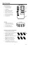
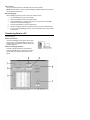
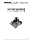
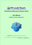
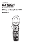
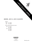
User's Guide
Heavy Duty Datalogger Module
Model 380340
Warranty
EXTECH INSTRUMENTS CORPORATION warrants this instrument to be free of defects
in parts and workmanship for one year from date of shipment (a six month limited
warranty applies on sensors and cables). If it should become necessary to return the
instrument for service during or beyond the warranty period, contact the Customer
Service Department at (781) 890-7440 ext. 210 for authorization or visit our website at
www.extech.com (click on ‘Contact Extech’ and go to ‘Service Department’ to request an
RA number). A Return Authorization (RA) number must be issued before any product is
returned to Extech. The sender is responsible for shipping charges, freight, insurance
and proper packaging to prevent damage in transit. This warranty does not apply to
defects resulting from action of the user such as misuse, improper wiring, operation
outside of specification, improper maintenance or repair, or unauthorized modification.
Extech specifically disclaims any implied warranties or merchantability or fitness for a
specific purpose and will not be liable for any direct, indirect, incidental or consequential
damages. Extech's total liability is limited to repair or replacement of the product. The
warranty set forth above is inclusive and no other warranty, whether written or oral, is
expressed or implied.
Introduction
Congratulations on your purchase of Extech’s 380340 Datalogger Module. The Datalogger
connects to and records data from Extech Heavy Duty Series Meters. The sample rate at
which data is recorded is user selectable. Readings stored in the Datalogger can later be
transferred to a PC using the supplied software and communication cables. This
professional device, with proper care, will provide years of safe reliable service.
Specifications
Input type
RS-232 data stream
Data storage
8000 readings (16 bits each)
Display
0.5" red 2 digit LED, 100 counts (0-99)
Adjustable Sample Rate
Seconds: 1 to 99; Minutes: 1 to 99; Hours: 1 to 99
Software compatibility
WindowsTM 98, 2000, Me, and XP Operating Systems
Internal Clock
Crystal oscillator
Memory
Non-volatile; Data is retained at power down
Batteries
Four 1.5V AA batteries (alkaline or heavy duty type)
Battery life
36 hours continuous (typical)
Power consumption
Approx. 20 to 54 mA DC
Operating temperature
32 to 122 F (0 to 50 C)
Operating humidity
< 80 % RH
o
o
Weight
0.45 lbs. (205g) including battery
Dimensions
5.2 x 2.8 x 1.0" (131 x 70 x 26mm) (H x W x D)
2
V2.0 3/04
Meter Description
1
FRONT PANEL VIEW
1.
Input / Output terminals
2.
PAUSE LED indicator
3.
LCD Display
4.
Battery LED status indicator
5.
Slide switches and buttons
6.
Battery compartment (on rear)
7.
Memory FULL LED indicator
8.
DATA recording LED indicator
9.
AC adaptor input
7
2
3
8
4
5
9
6
FRONT PANEL VIEW
TOP VIEW
1.
Optically isolated INPUT jack
2.
Optically isolated OUTPUT jack
3.
Non-isolated INPUT jack
4.
Non-isolated OUTPUT jack
TOP VIEW
ISOLATE
OUT
IN
1
IN
2
DIRECT
OUT
3
4
SLIDE SWITCH AND BUTTON DESCRIPTION
1.
Power slide switch (I=ON; O=OFF)
2.
Sample Rate slide switch: Secs, Mins, Hours
3.
S
I
1
Automatic or Manual Recording
O
2
M
H
AUTO
MAN
OUT
3
and Data Output slide switch
4.
RESET (memory clear) and sampling rate
RESET>
PAUSE
4
5
INCrement (left LCD digit) button
5.
INCrement (right LCD digit) button
6.
6
PAUSE recording and sampling rate
INC.10
INC.1
SET
Hold the SET button while pressing
an increment button to change the sample rate
3
V2.0 3/04
Datalogger Operation
Note: The Heavy Duty Meters have an Auto-Shutoff feature that automatically turns off the
meter (after 10 to 30 minutes depending on the model). This feature should be disabled
during a datalogging session. Press the ‘RECORD’ button on the meter to disable the AutoShutoff feature.
Automated Datalogging Preparation
This function permits the Datalogger to automatically collect readings at the sample rate
set by the user.
1. Connect the Datalogger's IN port to the Heavy Duty Meter as shown in the
illustration. (The supplied cable connects the Heavy
Duty meter to the Datalogger). Use the Isolated or
Direct (non-isolated) port on the Datalogger as desired.
2. Turn the Datalogger OFF (‘0’ switch position).
3. Slide the Auto/Man/Out switch to the Auto position.
4. Slide the Time switch to the ‘S’ (seconds), ‘M’ (minutes)
or ‘H’ (hours) range position depending on the data
sampling rate desired.
5. If this is the first time the datalogger is being used,
reset (erase) the datalogger's memory per the Reset Function section below.
6. Power the datalogger (slide switch to the ‘I’ position).
7. To set the sample (recording) rate, press and hold the SET button and, while holding
the SET button, press the INC 1 button to adjust the units digit (use the INC 10
button to adjust the tens digit). Release the SET button when complete. You can set
the interval from 1 to 99 seconds, 1 to 99 minutes, or 1 to 99 hours.
Note: Always set the AUTO and TIME switches to the desired setting before turning
on the Datalogger.
Begin Automated Datalogging
1.
Press the PAUSE button to begin logging measurements. The PAUSE LED will
switch off and the DATA LED will blink each time a measurement is recorded.
2.
Press the PAUSE button a second time to pause datalogging (PAUSE LED lights).
3.
Use the PAUSE button to toggle recording ON (resume) and OFF (pause). When
datalogging is resumed, new readings are recorded right where the datalogger left
off so that readings are not overwritten.
RESET Function
The RESET function erases all of the stored Datalogger readings.
1. Connect the datalogger to the meter as previously described.
2.
Set the Auto/Man/Out switch to either the AUTO or MAN position.
3.
Power the datalogger and the meter.
4.
Press and hold the RESET button for approx. 4 seconds, until "00" is displayed.
NOTE: It may take up to three RESETS to clear all the datalogger memory levels. To be
sure, repeat the RESET procedure three times in succession.
4
V2.0 3/04
FULL Indicator
The FULL indicator lights when 7999 data points have been recorded.
NOTE: Data will remain in memory until the Datalogger is RESET (see previous section) or
until the batteries are removed.
Manual Datalogging
Manual datalogging allows the user to record one reading at a time.
1.
Turn the Datalogger OFF (‘0’ switch position).
2.
Slide the Auto/Man/Out switch to the MAN position.
3.
Power the Datalogger (‘I’ position). Note that it is very important to set the MAN
switch before turning the Datalogger on.
4.
Press the PAUSE button to log one measurement.
5.
When the Datalogger memory is full (7999 readings), the FULL indicator will light.
6.
To erase (reset) the Datalogger memory, refer to the Reset Function section earlier
in this manual.
Transferring Data to a PC
Once data is collected, the next step is to connect the Datalogger to a PC and transfer the
collected readings.
Hardware Connection
Connect the Datalogger’s OUT port to the PC COM
port as shown via the supplied cable (3.5mm phono
to DB-9 cable). Use either the Isolated or Direct (nonisolated) output port.
TM
Windows
Datalogger Software
TM
Install the supplied software from the Windows
program CD-ROM using the instructions provided on
the CD-ROM. The following software screen will
appear.
5
V2.0 3/04
Software Screen Description
1.
2.
3.
4.
5.
6.
7.
COM Port Selection (Click on appropriate port, COM1 or COM2)
Data Transfer Status
Transferred Data View
Data File Name (type desired filename)
Number of Data points
Instructional steps describing the data transfer process (additional steps are listed
in the next section).
Function buttons: START (click to begin data transfer); VIEW DATA (click to see all
transferred data as shown in item 3 above), and EXIT (click to close program)
Begin Data Transfer
To transfer data from a Heavy Duty meter to a PC, follow the instructions shown below:
1. Slide the Auto/Man/Out Datalogger switch to the OUT position.
2. Power the Datalogger.
3. Select COM 1 or COM 2 on the software screen.
4. Type a file name in the Data File Name field on the software screen.
5. Click on the START key in the software window
6. Press the RESET button on the Datalogger to begin the data transfer.
7. The DATA LED will rapidly blink as the data transfer takes place.
8. Press the PAUSE button to halt the transfer.
9. When the Data LED ceases blinking, the data points have been transferred.
10. After the data points have been transferred, turn off the datalogger. Data will
remain in the datalogger as long as the batteries are fresh.
The data points are transferred to the file named in step 4 above. To view the transferred
data, click the VIEW DATA button on the software screen. The file stored on the PC can
now be opened in other applications such as spreadsheet, word-processor, database or
graphics programs.
Battery Replacement
When the Battery Status LED indicator is NOT lit the batteries should be replaced. Slide
the rear battery cover off in the direction of the arrow. Replace the four ‘AA’ batteries and
secure the battery compartment cover.
Calibration and Repair Services
Extech offers repair and calibration services for the products we sell. Extech also provides
NIST certification for most products. Call the Customer Service Department for information
on calibration services available for this product. Extech recommends that annual
calibrations be performed to verify meter performance and accuracy.
Support Hotline (781) 890-7440
Tech support: Ext. 200; Email: [email protected]
Repair/Returns: Ext. 210; Email: [email protected]
Website: www.extech.com
Copyright © 2004 Extech Instruments Corporation
All rights reserved including the right of reproduction in whole or in part in any form.
6
V2.0 3/04