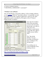
1
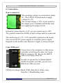
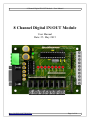
8 Channel Digital IN/OUT Module - User Manual
8 Channel Digital IN/OUT Module
User Manual
Date: 25. May 2015
www.CASINO-SOFTWARE.de
Page 1 of 14
8 Channel Digital IN/OUT Module - User Manual
Content
1. Introduction.................................................................................3
2. Features.......................................................................................3
3. Specification...............................................................................4
4. Applications examples................................................................4
5. Connections.................................................................................5
Power connector.........................................................................5
Com (USB) port..........................................................................5
Inputs..........................................................................................6
8 inputs connector pin out..........................................................6
Outputs........................................................................................7
8 outputs connector pin out........................................................7
6. Commands..................................................................................8
Serial port parameters.................................................................8
INPUT functions:.......................................................................9
OUTPUT functions:.................................................................10
7. Ready to use software...............................................................12
8. Safety instructions.....................................................................13
www.CASINO-SOFTWARE.de
Page 2 of 14
8 Channel Digital IN/OUT Module - User Manual
1. Introduction
The 8 channel digital IN/OUT module offers 8 digital input
channels and 8 digital output channels. Connection to the board is
done by serial com port. The module can be used to control
electrical devices, e.g. heaters, vans, pumps, valves, solid-state
relays and other power equipment for home automation as well as
industrial automation.
The module's 8 digital inputs can be used to determine the state of
push buttons, switches, relay contacts, limit or safety switches or
other digital signals. The number of inputs/outputs can be further
expanded by connecting more cards to the PC.
The 8 channel digital IN/OUT module is controlled by simple
commands. A complete overview of commands can be found in
the COMMANDS section below. You can write custom
applications with every programming language supporting COM
port functionality.
The diagnostic application (IO8.EXE) can also be used as
command line application. This way it is possible to control the
module by using batch file. Example batch files are included with
the diagnostic software.
2. Features
• 8 Digital inputs (e.g push button, switch, relay contact, ...)
• 8 Digital N-channel power MOSFET outputs (55V/30A).
• Input and output connection via simple screw terminals.
• Additionally on board plug to connect an 8 channel relays board.
• Every output has a LED indicator.
• Works on the USB (with USB to Serial converter) or serial port.
• Diagnostic software and example source code available on our
website https://www.casino-software.de/8inout/
www.CASINO-SOFTWARE.de
Page 3 of 14
8 Channel Digital IN/OUT Module - User Manual
3. Specification
• 8 digital N-channel power MOSFET outputs
IRLZ34N (55V/30A)
• 8 digital inputs channels, active LOW
• 9-pole serial connector - type EU-9F
• Power supply requirements: +5V DC / 500mA
• Communication: serial
• Led-s: Power ON Led, Output Led each channel
• Operating temperature range: from -30 ºC to +80 ºC
• PCB parameters: FR4 / 1.5mm / two layers / metalized holes /
HAL / white stamp / solder mask
• Dimensions: W=75mm x L=100mm x H=24mm
4. Applications examples
• Home automation
• Industrial automation
• Control electrical devices like lighting systems, heaters, cooling
vans, pumps, valves, solenoids, and more.
• Alarm system
• Model railway control
• Illuminated push button panel, e.g. slot machine
• ...
www.CASINO-SOFTWARE.de
Page 4 of 14
8 Channel Digital IN/OUT Module - User Manual
5. Connections
Power connector
The operating voltage is connected to clamp
X1. The 8 IN/OUT board needs a supply
voltage of +5V.
The second voltage (+12V) is just routed to
the output screw terminals and finally used
for supplying the output circuit.
Instead of connecting the +12V you can connect up to +24V.
The ground connection (GND) of both voltage must be connected.
The interfacing of +5V, +12V and GND is printed on the board.
You can use the PC power supply or a separate power supply.
Depends on the load be sure the power supply is strong enough!
Com (USB) port
Connection to the computer or other micro
controller circuit board is done via 9-pole
RS232 connector X2. Be sure the RS232
cable is not longer than 3m.
In order to operate the 8 channel digital
IN/OUT module via USB, you can use a
RS232 to USB converter.
COM port settings: Baud 19200, Data bits 8, Parity none,
Stop bits 1, Handshaking none
www.CASINO-SOFTWARE.de
Page 5 of 14
8 Channel Digital IN/OUT Module - User Manual
Inputs
Input is generally HIGH (1),
connection to ground makes the input LOW (0).
The inputs can be connected to the screw
terminals X8 – X12, or to the pin header JP1.
8 inputs connector pin out
JP1.1 - GND
X8.1, X8.2
JP1.2 - IN1
X9.1
JP1.3 - IN2
X9.2
JP1.4 - IN3
X10.1
JP1.5 - IN4
X10.2
JP1.6 - IN5
X11.1
JP1.7 - IN6
X11.2
JP1.8 - IN7
X12.1
JP1.9 - IN8
X12.2
JP1.10 - +5V
www.CASINO-SOFTWARE.de
(active low, open=1, ground=0)
(active low, open=1, ground=0)
(active low, open=1, ground=0)
(active low, open=1, ground=0)
(active low, open=1, ground=0)
(active low, open=1, ground=0)
(active low, open=1, ground=0)
(active low, open=1, ground=0)
Page 6 of 14
8 Channel Digital IN/OUT Module - User Manual
Outputs
The outputs can be connected to the screw terminals X3 – X7, or
to the pin header JP2.
8 outputs connector pin out
JP2.1 - +12V
X3.1, X3.2
JP2.2 - OUT1
X4.1
(active low, 0=open, 1=ground)
JP2.3 - OUT2
X4.2
(active low, 0=open, 1=ground)
JP2.4 - OUT3
X5.1
(active low, 0=open, 1=ground)
JP2.5 - OUT4
X5.2
(active low, 0=open, 1=ground)
JP2.6 - OUT5
X6.1
(active low, 0=open, 1=ground)
JP2.7 - OUT6
X6.2
(active low, 0=open, 1=ground)
JP2.8 - OUT7
X7.1
(active low, 0=open, 1=ground)
JP2.9 - OUT8
X7.2
(active low, 0=open, 1=ground)
JP2.10 - +5V
It is possible to connect an external relays board to jumper JP2 and
control high voltage devices.
You can find a suitable relay board in our web shop at
https://www.casino-software.de/shop/
www.CASINO-SOFTWARE.de
Page 7 of 14
8 Channel Digital IN/OUT Module - User Manual
6. Commands
Serial port parameters
Baud rate
Data bits
Stop bits
Parity
Handshaking
19200 bps
8
1
no
no
Commands to the 8 IN/OUT board must end with a "carriage
return". In computing, the carriage return (CR) hexadecimal 0D or
decimal 13, is one of the control characters in ASCII code. The
8 channel digital IN/OUT module detects a byte with the value
#13 ($0D) as command end.
Example: READ_IN_ALL$0D
All data from the 8 channel digital IN/OUT module ends with a
"carriage return" and "line feed" (CRLF = Enter). This way you
can detect the end of the data. When you receive the bytes
$0D$0A all data has been received and the data can be processed.
The communication from and to the 8 IN/OUT board can be tested
with a terminal program.
For each executed command, the 8 IN/OUT board controller sends
an answer frame.
Note that there must be minimum 5ms interval between every two
commands !
www.CASINO-SOFTWARE.de
Page 8 of 14
8 Channel Digital IN/OUT Module - User Manual
INPUT functions:
- READ_IN <number>
read status of an input
Value between 1 and 8 which corresponds to the input channel
whose status is to be read
Example: "READ_IN 8" read status of input 8
Returns: "READ_IN<number>=n" status of the input <number>
(0 = input is GND, 1 = input is OPEN)
- READ_IN_ALL
read status of all inputs
Example: "READ_IN_ALL"
Returns: "READ_IN_ALL =n"
bit 0 = input 1 (0 = input is GND, 1 = input is OPEN)
bit 1 = input 2 (0 = input is GND, 1 = input is OPEN)
bit 2 = input 3 (0 = input is GND, 1 = input is OPEN)
bit 3 = input 4 (0 = input is GND, 1 = input is OPEN)
bit 4 = input 5 (0 = input is GND, 1 = input is OPEN)
bit 5 = input 6 (0 = input is GND, 1 = input is OPEN)
bit 6 = input 7 (0 = input is GND, 1 = input is OPEN)
bit 7 = input 8 (0 = input is GND, 1 = input is OPEN)
- ON_IN_MESSAGE 0|1
automatically send a message if state of input changes, default = 1
"ON_IN_MESSAGE 0" send no message if state of input changes
"ON_IN_MESSAGE 1" send a message if state of input changes
Example: "ON_IN_MESSAGE 0" or "ON_IN_MESSAGE 1"
Returns: "ON_IN_MESSAGE=n". On Error "ERROR".
If an input state changes, the board sends a message
“IN<number>=n”
This way there is no need to poll the input(s) state!
www.CASINO-SOFTWARE.de
Page 9 of 14
8 Channel Digital IN/OUT Module - User Manual
OUTPUT functions:
- WRITE_OUT <data>
Set outputs according to data.
Value between 0 and 255 that is sent to the output port
(8 channels)
Example: "WRITE_OUT 255"
Returns: "WRITE_OUT=<data>"
bit 0 = output 1 (0 = set output to OPEN, 1 = set output to GND)
bit 1 = output 2 (0 = set output to OPEN, 1 = set output to GND)
bit 2 = output 3 (0 = set output to OPEN, 1 = set output to GND)
bit 3 = output 4 (0 = set output to OPEN, 1 = set output to GND)
bit 4 = output 5 (0 = set output to OPEN, 1 = set output to GND)
bit 5 = output 6 (0 = set output to OPEN, 1 = set output to GND)
bit 6 = output 7 (0 = set output to OPEN, 1 = set output to GND)
bit 7 = output 8 (0 = set output to OPEN, 1 = set output to GND)
- SET_OUT <number>
Set a single output
Value between 1 and 8 which corresponds to the output channel
that is to be set
Example: "SET_OUT 8" (set output 8 to GND)
Returns: "SET_OUT=<number>"
- SET_OUT_ALL
Set all outputs, same than command "WriteOut 255"
Example: "SET_OUT_ALL" (set output 1-8 to GND)
Returns: "SET_OUT_ALL=1"
www.CASINO-SOFTWARE.de
Page 10 of 14
8 Channel Digital IN/OUT Module - User Manual
- CLEAR_OUT <number>
Clear a single output
Value between 1 and 8 which corresponds to the output channel
that is to be cleared
Example: "CLEAR_OUT 8" (clear output 8)
Returns: "CLEAR_OUT=<number>"
- CLEAR_OUT_ALL
Clear all outputs, same than command "WriteOut 0"
Example: "CLEAR_OUT_ALL" (clears output 1-8)
Returns: "CLEAR_OUT_ALL=1"
- READ_OUT <number>
read status of an output
Value between 1 and 8 which corresponds to the output channel
whose status is to be read
Example: "READ_OUT 8" read status of output 8
Returns: "READ_OUT<number>=n" status of the output
<number> (0 = output is OPEN, 1= output is GND)
- READ_OUT_ALL
Receive the status of all outputs
Example: "READ_OUT_ALL"
Returns: "READ_OUT_ALL=n"
bit 0 = output 1 (0 = output is OPEN, 1 = output is GND)
bit 1 = output 2 (0 = output is OPEN, 1 = output is GND)
bit 2 = output 3 (0 = output is OPEN, 1 = output is GND)
bit 3 = output 4 (0 = output is OPEN, 1 = output is GND)
bit 4 = output 5 (0 = output is OPEN, 1 = output is GND)
bit 5 = output 6 (0 = output is OPEN, 1 = output is GND)
bit 6 = output 7 (0 = output is OPEN, 1 = output is GND)
bit 7 = output 8 (0 = output is OPEN, 1 = output is GND)
www.CASINO-SOFTWARE.de
Page 11 of 14
8 Channel Digital IN/OUT Module - User Manual
A wrong command returns:
"UNKNOWN_COMMAND=<command>"
7. Ready to use software
You can download a “keystroke edition” of the example software
on our website. With the “keystroke edition” it is possible to send
keystrokes to an other windows application. This way the other
application can be controlled by the inputs of the 8 Channel
Digital IN/OUT module!
Just enter the window
title of the keystroke
receiver and set up the
keystrokes you want to
send. It is even
possible to send mouse
events like left, right or
middle mouse button
click.
The “keystroke
edition” can run
invisible on Windows
boot, working in the
background.
Use sndmsg.exe to
send commands to the
running io8.exe
Another ready to use software can be found here:
http://www.bksoft.de/index_licht24pro_e.htm
www.CASINO-SOFTWARE.de
Page 12 of 14
8 Channel Digital IN/OUT Module - User Manual
8. Safety instructions
The 8 channel digital IN/OUT module is intended for installation
in a housing.
Only use the 8 channel digital IN/OUT module in low-voltage
circuits (max. 24V). Higher voltage rates are not permissible.
There is danger to life through an electric shock and a risk of fire!
Ensure that all the electrical connections and connection cables
conform to the regulations.
The entire product may not be modified or reassembled. Operation
is only permissible in dry indoor locations. Never operate the
device immediately after bringing it from a cold to a warm room.
The resulting condensation water may damage the device. Do not
expose the 8 channel digital IN/OUT module to high temperatures,
strong vibrations, high degrees of humidity or chemically
aggressive dusts, gases and vapors.
Electronic components of the 8 channel digital IN/OUT module
may heat up during operation. Ensure sufficient air circulation
around the device to prevent heat build-up and overheating.
On industrial sites the accident prevention regulations of the
association of the industrial workers' society for electrical
equipment and utilities must be followed.
In case of damage incurred by disregarding these operating
instructions, the warranty claim is void. Liability for any and all
consequential damage is excluded! We do not assume any liability
for damage to property or personal injury caused by improper use
or the failure to observe the safety instructions!
www.CASINO-SOFTWARE.de
Page 13 of 14
8 Channel Digital IN/OUT Module - User Manual
The 8 channel digital IN/OUT module was EMV tested according
to industrial and domestic standards and complies with both these
standards. Proof of CE conformity has been established and the
corresponding declarations are obtainable from the manufacturer.
This device complies with part 15 of the FCC rules provided the
enclosed instructions are followed to the letter. Use of the device
is subject to the following conditions: (1) this device must not
cause harmful interference and (2) the operation of this device
should not be influenced by unwanted interference. More
information about FCC can be found at http://www.fcc.gov
www.CASINO-SOFTWARE.de
Page 14 of 14