1
PLATECRANE EX
SOFTLINX
USER MANUAL
10 Stern Avenue, Springfield, NJ 07081
Tel: 973-376-7400 ♦ Fax: 973-376-8265
Table of Contents
CHAPTER 1--Introduction ............................................................................................... 1
Overview .................................................................................................................................... 1
Computer Requirements .......................................................................................................... 2
CHAPTER 2--Installation ................................................................................................. 4
Unpack the PlateCrane EX ...................................................................................................... 4
Parts List.................................................................................................................................... 6
Setting Up The PlateCrane EX ................................................................................................ 6
Connect Power Cord & Communication Cable:.................................................................... 6
Switching AC Line Voltage 110VAC/220VAC....................................................................... 7
Installing PlateCrane Stacks:................................................................................................... 8
Installing Barcode Scanner: ..................................................................................................... 8
Unplugging Power and Communication Cables: ................................................................... 8
CHAPTER 3—PlateCrane EX Software .......................................................................... 9
Brief Description of Software................................................................................................... 9
How to Install Software ............................................................................................................ 9
CHAPTER 4--Operation.................................................................................................. 11
CHAPTER 5--PlateCrane Components.......................................................................... 13
The Robotic Axes .................................................................................................................... 13
Stacks ....................................................................................................................................... 13
Power Cord/Communication Cable Connection.................................................................. 14
Power Switch ........................................................................................................................... 14
Optional Components ............................................................................................................. 14
CHAPTER 6--Hardware Specifications ......................................................................... 15
General..................................................................................................................................... 15
Robotic Arm ............................................................................................................................ 15
Mechanical Description .......................................................................................................... 15
Dimensions............................................................................................................................... 16
Electrical .................................................................................................................................. 16
Environmental......................................................................................................................... 16
CHAPTER 7--Maintenance ............................................................................................ 17
Maintenance ............................................................................................................................ 17
Cleaning the PlateCrane......................................................................................................... 17
PlateCrane EX User Manual
Hudson Control Group, Inc.
i
Change the Fuse(s) .................................................................................................................. 17
CHAPTER 8--Troubleshooting....................................................................................... 19
Appendix........................................................................................................................... 20
Hudson's PlateCrane Communications and Command Set ............................................ 20
Protocol Description ........................................................................................................................... 20
Command Set...................................................................................................................................... 22
Error Code Description ....................................................................................................................... 34
Warranty & Service Agreement Terms and Conditions..................................................... 35
A.
B.
Warranty.................................................................................................................................... 35
Service Agreements,.................................................................................................................. 36
PlateCrane EX User Manual
Hudson Control Group, Inc.
ii
WARNING- -
This product may be used only in the manner described in this manual.
When used other than as specified, the safety protections provided by the
equipment may be impaired.
TABLE OF SYMBOLS:
The following symbols are to alert your attention to important information or
warnings that may present some hazards. These symbols may not appear in the
manual or on the product.
WARNING
Possible hazardous situation could result in
serious injury.
NOTE
A statement that is cautionary; operating
tip; instrument damage may occur if not
followed.
HINT
Helpful hints and additional information
List of instructions; parts
LIST
Important information
♦
!
Specifications
Electrical Hazard
CAUTION
PlateCrane EX User Manual
Hudson Control Group, Inc.
iii
CHAPTER 1--Introduction
Overview
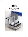
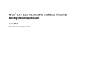
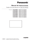
The PlateCrane EX (See Figure 1) is a multifunctional Pick & Place instrument with a
cylindrical robotic work envelope. It is designed to provide a simple answer to
automating laboratory instruments that employ microtiter plates. The PlateCrane EX is a
small and portable robotic system capable of handling up to thirty 96-well, 384-well or
1536-well microtiter plates per stack with a maximum capacity of 450 plates (15 stacks).
The PlateCrane EX has the ability to rotate up to a maximum of 345° about its base axis.
The standard software provided with the PlateCrane EX is called Softlinx and can run
multiple instruments in an easy to use "GUI" interface. Softlinx is written in the Visual
Basic for Applications programming language and can run on the Windows NT 4.0
w/Service Pack 6, Windows 98, Windows 2000, and Windows XP operating systems.
The PlateCrane EX can be interfaced with readers, washers, liquid handlers, labelers,
pipettors, etc. To prevent sample contamination, the PlateCrane can handle microtiter
plates with lids in conjunction with user defined input/output stacks.
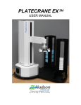
The PlateCrane EX is equipped with a Rotary Gripper and an extendable arm. With the
Rotary Gripper, the PlateCrane EX can handle plates in both portrait or landscape
configuration. The Rotary Gripper provides maximum flexibility with a 350° axis of
rotation. With the extendable arm, the PlateCrane EX has an additional 6” of travel.
With the additional 6” travel, the PlateCrane EX can now access nests anywhere within a
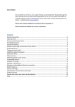
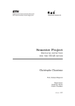
12”-18” radius from the center of its base. The PlateCrane EX also has two options
AutoTeach vision system (See Figure 3) and the EasyTeach teaching pendant (See Figure
2). The vision system is a camera that attaches to the Gripper. When used with the
vision teaching plates the software will calibrate the stacks and instruments on its own.
The teach pendant is a pendant that plugs into the PlateCrane and by the push of a button
can control any axis on the PlateCrane.
The PlateCrane setup and programming procedures are designed to be simple and
intuitive, requiring no more automation expertise than is required to operate a typical
plate washer or reader.
PlateCrane EX User Manual
Hudson Control Group, Inc.
1
Figure 1
EasyTeach
AutoTeach
Figure 2
Figure 3
Computer Requirements
The following are recommended for proper operation of the PlateCrane EX and Softlinx:
•
•
•
•
•
Windows OS (98 SE, ME, NT4.0 SP6, 2000 professional, XP professional or home
edition)
300 MHz Pentium processor or faster, 128 MB RAM or higher, 3½” floppy drive,
CD-Rom drive
100 MB of free disk space available
Internet explorer version 5.0 or above
Computer with the appropriate number of working serial ports
PlateCrane EX User Manual
Hudson Control Group, Inc.
2
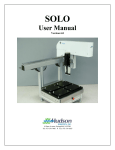
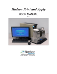
Stack
Magazine Base
Figure 4
Figure 5
Crane w/Stacks
Figure 6
PlateCrane EX User Manual
Hudson Control Group, Inc.
3
CHAPTER 2--Installation
Unpack the PlateCrane EX
WARNING- -
Power switch must be turned OFF during entire installation procedure
DO NOT loosen or tighten any screws or touch parts not specified in the
instructions
Never force any component to fit
The PlateCrane weighs ≈45 lbs. and should be handled with care to avoid
mishaps
Overview:
1. Remove PlateCrane EX from carton (place right arm underneath PlateCrane tower
and the left arm underneath the PlateCrane base. Once you have a good hold on the
unit gently lift the unit straight up. Make sure that the PlateCrane is separated from
the shipping foam. If you have a problem removing the PlateCrane use two people to
lift the PlateCrane out of the Box. One Person should lift the tower while the other
person lifts the base.)
2. Position the PlateCrane EX
3. Attach Magazine Base(s) to Crane Base (see Figure 6)
4. Install Stack(s) onto Stack Base (see Figure 6)
5. Connect power cord and communication cable to PlateCrane (see Figure 7)
6. Install Softlinx Software (see Chapter 3)
NOTE:
Please refer to parts list to verify that all parts are included in the PlateCrane
carton. If any parts are missing, please contact Hudson Control Group (see
Chapter 7 for Technical Support).
DO NOT DISCARD the PlateCrane carton. This carton has been specially
created for this product and must be used for any additional shipping of the
instrument to prevent damage.
PlateCrane EX User Manual
Hudson Control Group, Inc.
4
Power Cord Location
Communication Cable location
Figure 7
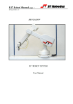
The Stacks can only be installed in one direction. The open side of the stack (Figure 8)
needs to be facing the PlateCrane EX and the closed end must face the user (Figure 9). In
Figure 10 you can see which way the stacks should be seated on the PlateCrane’s
magazine base: with the “open” side facing inward, toward the PlateCrane.
Figure 8
Figure 9
Stack
installed
correctly
Figure 10
PlateCrane EX User Manual
Hudson Control Group, Inc.
5
Parts List
The PlateCrane EX carton(s) should include the following:
PlateCrane EX
2 Extruded Stacks (additional Stacks optional)
Stack Base (additional Bases optional)
Power cord
Communication cable
User Manual (This document)
CD containing Softlinx and interfaces
Teaching plate(s)
Alignment Bases for instrument(s) (optional)
Gripper jaws for PlateCrane Gripper (Includes Allen Wrench)
Centering Plate for PlateCrane Gripper (Includes Allen Wrench)
Allen screws to attach Bases to PlateCrane
Allen Wrench for Stack and Alignment Base(s)
Setting Up The PlateCrane EX
Remove PlateCrane EX from the carton and carefully remove the protective
plastic covering.
Unwrap Stack Base and place it near the PlateCrane.
Remove the Stacks from the carton, then remove the stack from the packaging
Install the supplied Stack and Alignment Base(s), by securing then to the crane
base using the supplied screws.
Adjust the leveling feet on the PlateCrane EX and Stack Base(s) as required by
the surface that they are installed upon.
Connect Power Cord & Communication Cable:
Note: Power switch must be turned OFF (Figure 11)
Remove power cord and communication cable from PlateCrane carton.
On the rear side of the base unit housing connect one end of the 9-pin to 9-pin serial cable
(see Figure 7), and attach the other end into COM1 port on Host Computer.
Plug power cable into the PlateCrane's AC inlet located on rear side of the base unit
housing (see Figure 7).
Note: The communication cable & power cord should be securely plugged into
the PlateCrane and computer.
PlateCrane EX User Manual
Hudson Control Group, Inc.
6
Fuse holder door
0 – Power OFF position
1 – Power ON position
Figure 11
Switching AC Line Voltage 110VAC/220VAC
The power supplies installed in the unit are switching power supplies. That means they
are able to handle both 110VAC and 220VAC without any changes to their configuration.
The Run the PlateCrane on 220VAC perform the following:
Make sure the unit is powered off
Install the power cord that is supplying the 220VAC
Turn on unit
There is no other setup for the PlateCrane after this.
PlateCrane EX User Manual
Hudson Control Group, Inc.
7
Installing PlateCrane Stacks:
Note: Mishandling of plate stacks can result in misalignment.
Unpack and unwrap the input/output stacks
Mount the stacks onto the stack base by gently sliding them down onto the stack
guide blocks.
Installing Barcode Scanner:
If the Barcode Scanner option was purchased, position the scanner stand just
outside the outer edge of the plate magazines, so that a plate's label can be
scanned above the top of the stacks.
Secure the scanner platform to the scanner stand post, and run its RS-232 cable to
an available COM port on the host computer. Plug its 5-VDC power supply into a
nearby 120 VAC receptacle.
Unplugging Power and Communication Cables:
During service or moving the unit will have to have the power and
communication cable removed. To unplug the two cables perform the
following:
The Rear of the PlateCrane should be facing you (See figure 11)
Unplug the power cable by holding the power cable as close to the
PlateCrane as possible and pulling gently straight away from the
PlateCrane
Unplug the communication cable by loosening the two thumbscrews
that secure the cable to the PlateCrane then slowly pull the cable
straight away from the PlateCrane.
PlateCrane EX User Manual
Hudson Control Group, Inc.
8
CHAPTER 3—PlateCrane EX Software
Brief Description of Software
Hudson's standard PlateCrane application software (Software) can be found on one (1)
installation CD. This CD can be loaded onto any PC running Microsoft's Windows 98
SE, NT 4.0. w\service pack 6, 2000, or XP. This software provides a complete set of
utilities to run the PlateCrane EX and any instruments purchased by the end user.
Hudson’s SoftLinx is an easy-to-use, dynamic scheduling software program for control of
integrated lab automation workcells and systems. SoftLinx includes a multitasking core
executable combined with device interfaces that are written in VBA (Visual Basic for
Applications). The user sets up a method using a drag-and-drop icon-based method
editor.
How to Install Software
Turn computer ON. Start Windows, if it's not already running.
Insert CD into cd-rom drive, and then close the drawer
The CD has an auto run function, so the installation of the software is automatic
If the CD does not auto run, then click on the Start menu
Click the run menu, then type in the location of the CD and Setup.exe
(E:\Setup.exe)
Then click OK to start installation
Follow instructions as prompted to complete the installation.
After installing SoftLinx, open it by clicking the shortcut installed on your desktop. Then
click on the Help tab (Figure 12), and then click on help topics (Figure 13). This Help
document will tell you step by step how to setup your SoftLinx Workcells. If you have
any difficulty with the installation of your software or the configuration of the workcells,
please contact Hudson Control Group.
PlateCrane EX User Manual
Hudson Control Group, Inc.
9
Figure 12
Figure 13
PlateCrane EX User Manual
Hudson Control Group, Inc.
10
CHAPTER 4--Operation
SoftLinx provides an onscreen User Manual as part of the PlateCrane’s “Help” utility.
To access this, click and release the
button on SoftLinx’s main toolbar, shown here:
Figure 14
Move the mouse cursor over the PlateCrane bitmap, and then click again to obtain the
Help Menu for instruments in your workcell as shown below:
Figure 15
Select “PlateCrane” and the PlateCrane’s “Help” screen will be displayed:
PlateCrane EX User Manual
Hudson Control Group, Inc.
11
Figure 16
You can now select the topic of interest from the six choices in the “tree” in the left-hand
screen panel:
Description - provides an overview of the PlateCrane.
Configuration - describes how to set the PlateCrane’s serial port and operating
mode.
Setup - describes how to create and teach PlateCrane positions and movement
paths.
Method Editor - describes how to incorporate PlateCrane activities into a
SoftLinx method.
Run - describes how to start and run a method, which uses the PlateCrane.
Troubleshooting - describes some common errors/problems and their likely
causes.
You can also print any or all of the above topics to obtain a hardcopy of the PlateCrane’s
help utility.
PlateCrane EX User Manual
Hudson Control Group, Inc.
12
CHAPTER 5--PlateCrane Components
The Robotic Axes
The PlateCrane has the following axes:
1.
2.
3.
4.
R = rotates the PlateCrane horizontally
Z = moves the PlateCrane arm vertically
P = rotates the gripper horizontally
Y= extends/retracts the PlateCrane arm
The R-axis is driven by an encoded stepper motor. This axis has a rotational capability of
345°. It utilizes a hard stop to prevent continuous rotation, and a proximity sensor, which
determines the "Home" position for the horizontal rotation.
The Z-axis is driven by an encoded stepper motor. This axis can travel up to 18 inches
and complete a full stroke in less than three seconds. This axis utilizes a proximity
sensor, which determines the "Home" position and uses the top and bottom plates as its
hard stops.
The P-axis is driven by an encoded geared stepper motor. This axis has a rotational
capability of 350°. It utilizes a hard stop to prevent continuous rotation, and a proximity
sensor, which determines the "Home" position for the gripper rotation.
The Y-axis is driven by an encoded stepper motor. This axis can travel up to 6 inches
and complete a full stroke in 2 seconds. This axis utilizes a proximity sensor, which
determines the "Home" position, and uses the arm assembly for it’s hard stop.
The standard gripper consists of a pair of gripper fingers that have two rubber inserts that
provide a secure grip on microtiter plates. The lower part of the gripper “floats”
vertically, and locates microtiter plates by using a proximity switch. This switch is
located inside the gripper housing and indicates when the arm has encountered a
microtiter plate. The outside edge of a microtiter plate activates the floating gripper. A
centering plate is used to center microtiter plates inside the stack before the gripper picks
them up.
Stacks
The standard PlateCrane includes two extruded aluminum stacks. Each stack can hold up
to 30 standard-height microtiter plates. The stacks are from an aluminum extrusion for
rigidity and precision. The stacks are held in position by plastic guide blocks on a stack
base. The base is connected to the PlateCrane EX by three allen-head screws. The
PlateCrane can be upgraded to have a maximum capacity of fifteen (15) stacks on three
stack bases.
PlateCrane EX User Manual
Hudson Control Group, Inc.
13
Power Cord/Communication Cable Connection
The power cord plugs into the AC inlet on the rear of the PlateCrane. Input power is
either 120V or 230V, 50 or 60 Hz. The communication cable is connected from the rear
of the PlateCrane to the chosen serial port on the computer (usually COM 1).
Power Switch
The power switch is located on the side plate with the power cord and communication
cable (see Figure 11). It has a 0 and 1 engraved on it to show the OFF and ON power
condition of the PlateCrane (refer to Figure11). PlateCrane power is ON when the switch
is pressed in the 1 position and PWR LED on the rear of the PlateCrane is illuminated.
Optional Components
The following are additional items available for the PlateCrane:
Additional Stacks -- Expands PlateCrane capacity of up to 450 microtiter plates
(15 stacks).
Barcode Reader Kit -- Enables the PlateCrane to identify individual microtiter
plates by using bar code strips on the plates.
Device Interfaces -- Enables PlateCrane to work in conjunction with specific
laboratory instruments to process microtiter plates.
Instrument alignment bases – Enables the instruments to be locked to the
PlateCrane so they will not shift.
Vision Calibration System – This allows the user to use a camera attached to the
gripper with special calibration plates for teach PlateCrane positions. The camera
makes workcell setup both faster and more accurate.
Teach Pendant – This enables the end user to attached a teach pendant to the
PlateCrane. The Teach pendant comes with control buttons for the R-axis, Z-axis,
P-axis, Y-axis and also a limp button. The teach pendant saves time during setup,
especially if used in conjunction with the Vision Calibration System.
PlateCrane EX User Manual
Hudson Control Group, Inc.
14
CHAPTER 6--Hardware Specifications
General
Note: Specifications are subject to change without notice.
♦ Plate Capacity:
♦
♦
♦
♦
Plate Format:
Plate Storage Device:
Housing Material:
Gripper Material:
♦ Arm Mechanism:
Standard-- Up to 30 plates without lids or 25 plates
with lids.
Additional-- Up to 420 plates without lids or up to 350
plates with lids.
Portrait & Landscape - (Rotary Gripper)
2 removable stacks (expandable up to 15)
Painted steel covering cast aluminum housing.
Black anodized aluminum; textured neoprene rubber
inserts.
Ball bearing axis with high-speed screw rail;
mechanical stops to prevent continuous rotation (345°
maximum).
Robotic Arm
♦ Rotary Travel:
♦ Horizontal Reach:
♦ Vertical Reach:
345°
from center of crane 12” – 18” radius
Maximum 22.75 in. from table, minimum 4.25 in. from
table, total 18.0 in. vertical travel distance.
Mechanical Description
♦ R-axis Stepper Motor:
♦ Z-axis Stepper Motor:
♦ Rotary Gripper
Stepper Motor:
♦ Telescoping Motor:
Encoded 200 steps per motor revolution; +/-0.025°
resolution; approx. 3 seconds per full rotation (345°).
Encoded 200 steps per motor revolution; +/- 0.015mm
resolution; approximately 1.5 seconds per complete
vertical travel (one direction).
200 steps per motor revolution; +/- 0.030° resolution;
approx. 4 seconds per full rotation (350°).
Encoded 200 steps per motor revolution; +/- 0.032mm
resolution; approx. 1 second per full extension (6”).
PlateCrane EX User Manual
Hudson Control Group, Inc.
15
♦ Home Position:
Proximity Switch for rotary and vertical arm home
(zero) ranging, with encoder homing pulse for final
home position.
♦ Plate Present:
Proximity switch
♦ Plate Sensor:
Proximity Switch.
Dimensions
♦ Height:
♦ Weight:
28.5in. - 29.0in. (27.7in. w/out footpads)
≈45 lbs.
Electrical
♦ Power Input:
♦ Fuses:
♦ Grounding:
♦ Computer Interface:
120V / 230V AC, 50/60 Hz
(Determined by position of fuse holder)
For 120V / 230V
One 2A Time Delay, 5mm x 20mm
(.205 in. x .787 in.)
Through the power cord, must be properly earth
Grounded
RS-232 serial cable
Environmental
♦
♦
♦
♦
♦
Operating Temperature:
Operating Humidity:
Storage Temperature:
Altitude:
Ventilation
15° to 40°C (59° to 104°F)
0 to 85%, no condensation
-20° to 65°C (-4° to 149°F)
Up to 2000m
Fans Require +2” of free space in front of them
Indoor Use Only
PlateCrane EX User Manual
Hudson Control Group, Inc.
16
CHAPTER 7--Maintenance
Maintenance
WARNING- -
Qualified personnel can perform all maintenance procedures in this
manual. Only Hudson representatives should perform any maintenance
not discussed in this manual.
Gloves should be worn during any cleaning procedure.
Cleaning the PlateCrane
Note: DO NOT use/spray abrasive cleaners onto PlateCrane.
Clean the outside surfaces of PlateCrane using cloth or sponge dampened with
alcohol, water, or mild glass cleaner.
Clean finger pads of gripper with alcohol or other residue-free solvent.
Clean any spills on PlateCrane immediately.
Only clean the exterior of the unit. DO NOT remove instrument covers to clean
inside.
Never allow water or fluid to leak inside the PlateCrane.
Change the Fuse(s)
Extra fuses are shipped with the PlateCrane. Fuses burn out occasionally and must be
replaced. The following fuses are used with the PlateCrane:
Metric: 1 x 2 amp, 5 x 20 mm Time Delay Fuse
WARNING- -
Be sure the power to the PlateCrane is OFF and the power cord is
unplugged from the instrument or power source before proceeding with
the following instructions.
Turn the PlateCrane OFF and remove the power cord from the AC inlet on the back
of Crane.
Using a small flat head screwdriver, gently pry the fuse holder tray away from its
housing to access the fuses (see Figure 17). The Fuse holder door swings down.
PlateCrane EX User Manual
Hudson Control Group, Inc.
17
Remove the blown fuse. Replace it with the spare fuse.
Slide the fuse holder tray back into the AC inlet until it clicks. Make sure when reinstalling the holder the AC line voltage reads the correct way on the inlet
Reconnect the power cord to the PlateCrane and reconnect all other cables
previously disconnected.
Verify correct fuse replacement by turning the PlateCrane switch to ON position-the light will illuminate immediately.
Location of fuse
holder tray
Figure 17
PlateCrane EX User Manual
Hudson Control Group, Inc.
18
CHAPTER 8--Troubleshooting
For Troubleshooting Guide please contact Hudson Control Group
PlateCrane EX User Manual
Hudson Control Group, Inc.
19
Appendix
Hudson's PlateCrane Communications and Command Set
Version 5.0
Hudson's PlateCrane is designed to respond to a simplified set of ASCII commands to
allow any user program capable of reading/writing via an RS-232 port to exercise all the
features of the PlateCrane.
Protocol Description
The RS-232 controller of the PlateCrane operates with the following communication
specifications:
Baud Rate:
Data Bits:
Stop Bits:
Parity:
Handshake:
Device Type:
Connector:
9600
8
1
None
None
DCE
9-pin, female
All commands consist of an ASCII command, followed by a space and a list of commaseparated arguments (if appropriate), then a two-byte end-of-line carriage return/line
feed, as in the example:
HERE STACK1<13><10>
The "<>" symbols are not actually part of the protocol, but are used here to denote bytes
that are represented as their decimal number equivalent (i.e. <13> denotes a byte of value
13, a carriage return). The above command's individual byte values, for instance, would
be:
H
72
E
69
R E
82 69 32
S T A C
83 82 65 67
K 1 <13> <10>
75 49 13
10
Note: - commands are not case-sensitive and the space is important
- point names are case-sensitive
The PlateCrane will echo every byte back to the sender. Upon detecting the two bytes
<13><10>, the controller will then execute the command. Upon completing execution,
the controller will respond in one of two ways:
1. For query commands, where a data response is required, it will return:
PlateCrane EX User Manual
Hudson Control Group, Inc.
20
ASCII Response, plus <13><10>
2. For action commands, it will return:
2-byte ASCII error code, plus <16><13><10>
The "error code" will be two ASCII digits, from "00" to "99". "00" represents a correctly
executed command. Any other response indicates an error. An invalid query command
will produce a 01<16><13><10> response. As examples:
1. Valid query command:
Command:
Echo:
Response:
INPUT R,2<13><10>
INPUT R,2<13><10>
0<13><10> (i.e., input no. 2 is OFF)
2. Valid action command:
Command:
Echo:
Response:
CLOSE <13><10>
CLOSE <13><10>
00<16><13><10> (i.e., action successfully executed)
3. Invalid query command ("WASHER" is an unknown position):
Command:
GETPOINT WASHER <13><10>
Echo:
GETPOINT WASHER <13><10>
Response:
02<16><13><10> (invalid point name)
Note: If any command contains an error, the PlateCrane sends the error code and
<16><13><10> immediately, otherwise the 00<16><13><10> bytes are sent at the
completion of execution.
PlateCrane EX User Manual
Hudson Control Group, Inc.
21
Command Set
The PlateCrane recognizes the following commands:
1. CJOG Axis, Speed
CJOG will cause the specified Axis to move at the indicated speed until a HALT
is issued. Specifying a negative speed will reverse the direction of motion.
Example:
Command:
Response:
CJOG P,-200 <13><10>
00<16><13><10>
2. CLEARPOINTS
CLEARPOINTS will delete all the points that are stored in the PlateCrane
controller. Example:
Command:
Response:
CLEARPOINTS <13><10>
00<16><13><10>
3. CLOSE
CLOSE will close the PlateCrane's gripper.
Example:
Command:
Response:
CLOSE<13><10>
00<16><13><10>
4. DELETEPOINT Name
DELETEPOINT will delete the point given by 'Name' from the point list in the
PlateCrane memory. The PlateCrane will return an error if the point doesn't exist
Example:
Command:
Response:
DELETEPOINT READER<13><10>
00<16><13><10>
5. GETCONFIG
GETCONFIG will return a number whose bits indicate the PlateCrane options:
0 Rotary Option Present
1 EX Arm Option Present
2 Parallel Gripper Option Present
3 PlateCrane E Series (Cannot be unset)
Example:
Command:
Response:
GETCONFIG<13><10>
11<13><10>
PlateCrane EX User Manual
Hudson Control Group, Inc.
22
6. GETGRIPSTRENGTH
GETGRIPSTRENGTH will return the current gripper strength setting. Strength
settings are numbered 0-3, with 3 being the highest. (see SETGRIPSTRENGTH)
Example:
Command:
Response:
GETGRIPSTRENGTH<13><10>
3<13><10>
7. GETLIMITS
GETLIMITS will return the PlateCrane minimum and maximum position limits
for each axis. The order of the values in the response are:
R low limit, R high limit, Z low limit, Z high limit, P low limit, P high limit, Y
low limit, Y high limit
(see SETLIMITS)
Example:
Command:
Response:
GETLIMITS<13><10>
–150,14000,-12450,75,0,8500,-19000,200<13><10>
8. GETPOINT Name
GETPOINT will return the PlateCrane R, Z, P, Y positions value given by 'Name'.
The PlateCrane will return an error if the point doesn't exist (use the HERE
command to teach a point)
Example:
Command:
Response:
GETPOINT READER<13><10>
1050,-4000,90,0<13><10>
9. GETPOS
GETPOS will return the PlateCrane current R, Z, P, Y position values. An error
will be returned if the PlateCrane hasn’t been homed.
Example:
Command:
Response:
GETPOS<13><10>
1050,-4000,90,0<13><10>
PlateCrane EX User Manual
Hudson Control Group, Inc.
23
10. GETSPEEDS
GETSPEEDS will return the PlateCrane maximum speed for each axis. The order
of the values in the response are:
Maximum R speed, Maximum Z speed, Maximum P speed, Maximum Y speed
(see SETSPEEDS)
Example:
Command:
Response:
GETSPEEDS <13><10>
10000,30000,4000,20000<13><10>
11. GETSWITCHTYPE SwitchNumber
GETSWITCHTYPE will return the type and active-state of the specified internal
limit switch input. See SETSWITCHTYPE for more information.
Example:
Command:
Response:
GETSWITCHTYPE 1<13><10>
1,0<13><10>
12. GETZCURRENT
GETZCURRENT will return the running current settings for the Z axis. The first
number indicates the percentage of maximum current used when moving down,
the second is the percentage used when moving up.
Example:
Command:
Response:
GETZCURRENT<13><10>
15,45<13><10>
13. HALT
HALT will stop all current PlateCrane motion. It is the only command
whose successful completion results in an error code other than "00".
Example:
Command:
Response:
HALT<13><10>
15<16><13><10>
14. HERE Name
HERE will read the current PlateCrane position and store it in the PlateCrane's
non-volatile memory with the given 'Name'. 'Name' can be any string up to 20
characters long. The PlateCrane can store up to 50 positions in its memory.
Example:
Command:
Response:
HERE READER<13><10>
00<16><13><10>
PlateCrane EX User Manual
Hudson Control Group, Inc.
24
15. HOME
HOME will home the PlateCrane Y, Z, R, and P axes. The PlateCrane first will
home the Y-axis, the Z-axis and then the R and P axes.
Example:
Command:
Response:
HOME<13><10>
00<16><13><10>
16. JOG Axis,Steps
JOG will move the axis 'Axis' the number of steps given by 'Steps' relative to the
current position of the PlateCrane.
Example:
Command:
Response:
JOG Z,-1000<13><10>
00<16><13><10>
Command:
Response:
JOG P,45<13><10>
00<16><13><10>
17. LIMP PowerOn
LIMP will restore or remove power from the PlateCrane motors, depending on the
value of PowerOn. If PowerOn is a 1, the motors will be powered. If PowerOn is a 0
power will be removed. Other values are invalid. This will allow the user to move
the arm manually. The encoder positions will continue to update while motor power
is off.
Example:
Command:
Response:
LIMP 0<13><10>
00<16><13><10>
18. LISTPOINTS
LISTPOINTS will list all the points that are stored in the PlateCrane memory.
Example:
Command:
Response:
LISTPOINTS<13><10>
1:STACK1, 1000,-7000,0,-300<13><10>
2:STACK2, 1350,-7000,0,-300<13><10>
3:READER, 8500,-5670,1,-18024<13><10>
4:BARCODE, 4500,-2700,1,-18341<13><10>
<13><10>
PlateCrane EX User Manual
Hudson Control Group, Inc.
25
19. LOADPOINT Name,Rpos,Zpos,Ppos,Ypos
LOADPOINT will load the point name and the positions that are given by Rpos,
Zpos, Ppos,Ypos into the PlateCrane none volatile memory. This command
should be executed when it is required to load a position from backup.
Example:
Command:
Response:
LOADPOINT READER,4550,-7865,0,-1000<13><10>
00<16><13><10>
20. MOVE Name
MOVE will move the plate crane to the taught point given by 'Name'.
Example:
Command:
Response:
MOVE READER<13><10>
00<16><13><10>
21. MOVE_ABS Axis,Position
MOVE_ABS will move the axis 'Axis' to the absolute position given by 'Position'.
Example:
Command:
Response:
MOVE_ABS Z,-1000<13><10>
00<16><13><10>
Command:
Response:
MOVE_ABS P,45<13><10>
00<16><13><10>
22. MOVE_P Name
MOVE_P will move the PlateCrane P axis to the taught point given by 'Name'.
Example:
Command:
Response:
MOVE_P READER<13><10>
00<16><13><10>
23. MOVE_R Name
MOVE_R will move the PlateCrane R axis to the taught point given by 'Name'.
Example:
Command:
Response:
MOVE_R READER<13><10>
00<16><13><10>
PlateCrane EX User Manual
Hudson Control Group, Inc.
26
24. MOVE_Y Name
MOVE_Y will move the PlateCrane Y axis to the taught point given by 'Name'.
Example:
Command:
Response:
MOVE_Y READER<13><10>
00<16><13><10>
25. MOVE_Z Name
MOVE_Z will move the PlateCrane Z axis to the taught point given by 'Name'.
Example:
Command:
Response:
MOVE_Z READER<13><10>
00<16><13><10>
26. OPEN
OPEN will open the PlateCrane's gripper.
Example:
Command:
Response:
OPEN<13><10>
00<16><13><10>
PlateCrane EX User Manual
Hudson Control Group, Inc.
27
27. READINP Number
READINP will return the current state of the digital input 'Number', returning "0"
(OFF) or "1" (ON). 'Number' can have the values "1" through "48" for the input
address:
"1" is the R axis home switch
"2" is the Z axis home switch
"3" is the Stack Height sensor
"4" is the Gripper Fully Closed sensor
"5" is the Rotary Gripper home switch
“6-8” are unused
“9-12” are JackRabbit Port B inputs 2-5
“13” is the left Address Input (JackRabbit Port D input 0)
“14” is the right Address Input (JackRabbit Port D input 3)
“15” if the R axis home switch
“16”-“18” are the R axis driver inputs 2-4
“19”-“20” are unused
“21” is the Z axis home switch
“22” is the Stack Height sensor
“23”-“24” are the Z axis driver inputs 3-4
“25”-“26” are unused
“27” is the P axis lower limit
“28” is the P axis upper limit
“29”-”31” are the P axis driver inputs 0-2
“32” is the P axis home switch
“33” is the Y axis lower limit
“34” is the Y axis upper limit
“35”-“37” are the Y axis driver inputs 0-2
“38” is the Y axis home switch
“39”-“40” are unused
“41”-“48” are the Teach Pendant inputs (JackRabbit Port A 0-7)
Command:
Response:
READINP 1<13><10>
0<13><10> (input is off)
28. SET Source, Destination
SET will copy the PlateCrane coordinates of position name 'Source' to the
position name given by 'Destination'.
Example:
Command:
Response:
SET READER,TEMP<13><10>
00<16><13><10>
PlateCrane EX User Manual
Hudson Control Group, Inc.
28
29. SETCONFIG config_pattern
SETCONFIG will set the PlateCrane options present on this PlateCrane. Each bit
of the configuration pattern indicates an option.
0 Rotary Gripper
1 EX Arm
2 Parallel Gripper
3 PlateCrane E Series (will be set regardless of indicated value)
Example:
Command:
Response:
SETCONFIG 11<13><10>
00<16><13><10>
30. SETGRIPSTRENGTH strength
SETGRIPSTRENGTH will set the PlateCrane gripper strength. Valid settings are
0-3 with 3 being the strongest.
Example:
Command:
Response:
SETGRIPSTRENGTH 3<13><10>
00<16><13><10>
31. SETLIMITS Rmin,Rmax,Zmin,Zmax,Pmin,Pmax,Ymin,Ymax
SETLIMITS will set the minimum and maximum position limits for each axis, as
given by Rmin, Rmax, Zmin, Zmax, Pmin, Pmax, Ymin, Ymax. The P axis limits
are optional and are only used with the rotary gripper option. (see GETLIMITS)
Example:
Command:
Response:
SETLIMITS –150,14000,-12450,75,0,8500,-19000,200<13><10>
00<16><13><10>
32. SETSPEEDS RSpeed,[ZSpeed],[PSpeed],[YSpeed]
SETSPEEDS will set the PlateCrane maximum speed for each axis
(see GETSPEEDS)
Example:
Command:
Response:
SETSPEEDS 10000,30000,4000,20000<13><10>
00<16><13><10>
PlateCrane EX User Manual
Hudson Control Group, Inc.
29
33. SETSWITCHTYPE SwitchNumber, Type, ActiveState
SETSWITCHTYPE will set an internal PlateCrane limit switch to the specified
Type and ActiveState. Can be used to change the function of a given sensor.
1
2
3
4
5
6
7
8
The SwitchNumbers and their standard use are:
R-Axis Home switch
Unused
Unused
Unused
Z-Axis Home switch
Z-Axis Low Limit switch (Plate Detection switch in the gripper)
Unused
Unused
Valid Types are:
0 Generic Read Switch (default for unused switches)
1 Home
2 + Limit
3 - Limit
4 Go
5 Soft Stop
6 Pause
7 + Jog
8 - Jog
ActiveStates are:
0 Active Low (switch is “ON” when grounded or at 0V)
1 Active High (switch is “ON” when powered or above 5V)
Example: (re-casts the Z-Axis Low Limit switch as a generic input)
Command:
Response:
SETSWITCHTYPE 6,0,0<13><10>
00<16><13><10>
34. SETZCURRENT DownCurrent, UpCurrent
SETZCURRENT will set the PlateCrane Z-Axis running current to the specified
percentages. DownCurrent specifies the percentage of current to use when
moving down. UpCurrent specifies the percentage to use when moving up.
Example:
Command:
Response:
SETZCURRENT 15,45<13><10>
00<16><13><10>
PlateCrane EX User Manual
Hudson Control Group, Inc.
30
35. SHIFT Point,Rpos,Zpos,Ppos,Ypos
SHIFT will shift the point name Point by the axis positions given by Rpos, Zpos,
Ppos and Ypos. All values represent stepper pulses.
Example:
Command:
Response:
SHIFT READER,100,-2000,45,0<13><10>
00<16><13><10>
36. SPEED Speed
SPEED will set the PlateCrane movement speed to the variable 'Speed' percent of
full speed. 'Speed' can have any value 1 to 100.
Example:
Command:
Response:
SPEED 50<13><10>
00<16><13><10>
37. STATUS
STATUS will return the PlateCrane current status.
0 – Not Initialized
1 - Initialized
Example:
Command:
Response:
STATUS<13><10>
0<13><10>
Command:
Response:
STATUS<13><10>
1<13><10>
38. TEACH mode
The TEACH command enables or disables the Teach Pendant. A 1 activates the
Teach Pendant, while a 0 disables it. The Teach Pendant is enabled by default on
power-up. It is recommended that this command be issued to prevent user
interference during computer operation of the PlateCrane.
Example:
Command:
Response:
TEACH 1<13><10>
00<16><13><10>
PlateCrane EX User Manual
Hudson Control Group, Inc.
31
39. TERMINAL
TERMINAL will set the PlateCrane controller in terminal mode. When the
PlateCrane is in terminal mode incoming characters from the host are sent directly
to the motor controllers. This will enable the user to operate the individual axes
using the controller's own command language. To disable the terminal mode, type
TERMINAL again. To operate the Y and P axes in single-mode the command
“YA56” or “PA56” should be sent to the driver. This will place the driver in
single-mode until the drivers are reset by sending an ASCII 3, or until the
command “A24” is sent. The Z and R axes can be placed in single mode by
sending the command “ZPY 0” or “RPY 0”. This will place the driver in singlemode until the drivers are reset by sending an ASCII 3, or until the command “PY
1” is sent.
Example:
Command:
Response:
TERMINAL<13><10>
00<16><13><10>
40. VERSION
VERSION will report the PlateCrane firmware version
Command:
Response:
VERSION<13><10>
PlateCrane v5.0<13><10>
PlateCrane EX User Manual
Hudson Control Group, Inc.
32
41. WRITEOUT Number, State
WRITEOUT will set output 'Number' to the state given by 'State' ("1" = ON,
"0" = OFF). All other outputs are left unaffected. 'Number' can have the values
"1" through "36" for the output address:
"1”-“8" are JackRabbit Port A outputs 0-7 (not currently available)
"9" is the left Address output (JackRabbit Port B output 6)
"10" is the right Address output (JackRabbit Port B output 7)
“11”-“12” are JackRabbit Port D outputs 6-7
“13”-“16” are JackRabbit Port E outputs 0-3 and High Current Outputs 0-3
“17”-“18” are JackRabbit Port E outputs 4-5
“19” is JackRabbit output PCLK
“20” is JackRabbit output IOBEN
“21”-“24” are the R axis driver outputs 1-4
“25”-“29” are the Z axis driver outputs 1-4
“30” is the open gripper output
“31” is the close gripper output
“32” is the P Axis Party Mode output
“34” is the second Grip Strength output
“35” is the first Grip Strength output
“36” is the Y Axis Party Mode output
Command:
Response:
WRITEOUT 1,0<13><10> (turn output 1 off)
00<16><13><10>
Command:
Response:
WRITEOUT 3,0<13><10> (turn output 3 on)
01<16><13><10> (error: invalid output)
PlateCrane EX User Manual
Hudson Control Group, Inc.
33
Error Code Description
The PlateCrane controller will report one of the following response codes at the
completion of each command:
00
01
02
03
04
05
06
07
08
09
10
11
12
13
14
15
16
17
Command completed successfully.
Invalid command or parameter.
Invalid point name
Maximum number of points exceeded
IMS communication transmit error
IMS communication response error
Move command wasn't complete
Home command wasn't complete
Invalid target position
PlateCrane is not homed
R axis position is out of the dead-band limit
Z axis position is out of the dead-band limit
P axis position is out of the dead-band limit
Invalid rotary option.
Plate present
Motion halt
No plate in gripper
Y axis position is out of the dead-band limit
PlateCrane EX User Manual
Hudson Control Group, Inc.
34
Warranty & Service Agreement Terms and Conditions
A. Warranty
a. One-year coverage beginning on the factory ship date on all parts and
labor including return shipping (to the customer) via UPS ground or
equivalent. Warranty is limited to components and software purchased
from or provided by Hudson Control Group, Inc.
b. Technical support by trained personnel via telephone or email during
normal business hours will be provided at no cost (exclusive of telephone
toll charges incurred by the customer) during the warranty period.
c. Hudson Control Group, Inc. will provide on-site service during the
warranty period, excluding Micro1 and Micro10 instruments.
d. Factory repair services are available for all products, under the following
conditions:
1. The customer is responsible for packing of instrument and
shipping to Hudson. The customer will be notified of nonwarranty repair costs, if any, prior to the repair being started.
2. Damage incurred in transit to Hudson including, but not limited to,
damage due to improper packing will be the responsibility of the
customer and / or shipper. The customer is advised to retain the
original packing material, including the cast foam padding, in the
event service is required. Replacement packing materials are
available from Hudson at cost-plus shipping (currently ~$175.00).
3. Hudson will pay return shipping to customer, via UPS ground or
equivalent. Expedited shipping is available at additional cost.
e. Updates to correct performance anomalies shall be provided at no cost
during the warranty period subject to the warranty terms and conditions.
f. Upgrades, which provide additional functionality, may be offered at
reduced costs during the warranty period.
g. Factory repairs must be pre-authorized by Hudson Control Group, Inc. and
will include issuance of a Returned Materials Authorization (RMA)
number. Customer certification of decontamination is required prior to
return of any instrument(s) for factory service (instruments not certified
decontaminated may be refused service and returned at customer’s
expense).
h. While Hudson Control Group, Inc. makes every effort to provide software
and instruments suitable to
a wide range of automation tasks, no guarantee is made as to the suitability
of the hardware and/or
software provided for a given application unless so stated in the written
purchase agreement.
i. Repair of failures, caused by but not limited, to misuse, fire, flood or other
act of God, chemical or
environmental exposure, or repair by persons not authorized by Hudson
Control Group, Inc. may, at
the sole discretion of Hudson Control Group, Inc., be charged at the
prevailing hourly service rate
PlateCrane EX User Manual
Hudson Control Group, Inc.
35
(currently $120/hr for Factory Service, $120/hr for travel time and $240/hr
for Field Service).
B. Service Agreements,
Service Agreements in one-year periods are available at prevailing rates and
provide the following coverage
in addition to the original warranty:
a. One scheduled onsite maintenance service call per year of coverage to
include evaluation and
adjustments/repairs to meet instrument performance specifications.
b. Inspection and replacement of marginal components.
c. All applicable hardware and software updates.
d. If previous warranty or service agreement coverage has expired for more
than 30 days pre-inspection
and repair of instrument at customers expense prior to start of service
coverage may be required.
e. Pre-inspection may, at the service director’s discretion, be provided in
place of the one scheduled
onsite maintenance at no charge beyond that of the service agreement.
f. Onsite service is priced by travel time to customer from an established
Hudson site.
1. Zone I: Massachusetts, Connecticut, Rhode Island, New Jersey,
New York, Pennsylvania,
Delaware, and Maryland, and California north of Santa Barbara.
2. Zone II: All other.
g. Payment terms are net thirty (30) days after the date of invoice. Customer
will be invoiced. In case of
delayed payment, Hudson Control reserves the right to decline service.
h. This agreement may be terminated by either party upon default by the
other party of any material
obligation under this Agreement which default continues for thirty (30)
days after written notice has
been provided by the non-defaulting party.
II. General Conditions. These apply to all products under warranty or service
agreement.
a. Excluded parts. Covered parts do not include chemicals, reagents, customer
replaceable items,
consumables, or other parts listed in the operator's or instruction manual as
customer replaceable parts,
sub-assemblies or accessories. Replacement of these items will be billed at
prevailing rates.
b. Hudson Control reserves the right to use repaired parts during the Coverage
Period. For parts that have
been replaced, Hudson Control is the sole owner of these parts and they
cannot be sold or repaired by
PlateCrane EX User Manual
Hudson Control Group, Inc.
36
the customer or any third party.
c. Key operator. Customer shall designate a key operator to a Hudson Control
representative by
telephone or email. Such operator shall be qualified to perform simple
adjustments or corrections as
requested by a Hudson Control representative. Failure to perform customer
maintenance as specified in
the Instrument Instruction Manual may result at Hudson Control’s option in 1)
cancellation of this
Agreement or 2) a service call invoiced by Hudson Control at its standard
rates for service including
travel.
d. Warranty and service coverage does not include the following. Any
service calls made as the result
of the below shall be invoiced by Hudson Control at their standard rates
including travel and labor
expenses:
1. Damage caused by Customer misuse or operation outside of conditions
prescribed in the
Instruction Manual.
2. Damage caused by electrical surges or the use of improper sources,
intervention of a third
party, external influences such as fire, water damage, natural disaster,
etc.
3. Relocation of the instrument.
4. Use of chemicals and accessories outside the specifications contained
in the Instruction
Manual.
5. Applications related issues.
6. Computer/ Hard drive crashes and failures
e. Safe Working Environment. Customer shall provide the Hudson Control
representative with facilities
at Customer's location that comply with the applicable regulations of the
Secretary of Labor
promulgated under the Occupational, Safety and Health Act of 1970.
f. This agreement sets forth the entire agreement and understanding between
Hudson Control and Customer
regarding service of the Instruments covered hereunder. This agreement may
be modified only by
writing and by authorized representatives of the parties.
III. Custom Service Packages providing features to meet individual customer
requirements may be arranged.
Contact your sales representative or Hudson’s service director for availability and
pricing.
PlateCrane EX User Manual
Hudson Control Group, Inc.
37