1
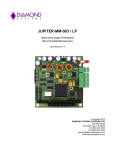
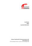
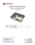
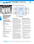
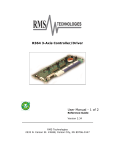
OPAL-MM Optoisolator and Relay Digital I/O PC/104 Module User Manual V1.22 Copyright 2001-2004 DIAMOND SYSTEMS CORPORATION 8430-D Central Ave. Newark, CA 94560 Tel (510) 456-7800 Fax (510) 456-7878 [email protected] www.diamondsystems.com TABLE OF CONTENTS 1. DESCRIPTION .......................................................................................................................... 3 2. FEATURES ............................................................................................................................... 3 3. OPAL-MM BOARD DRAWING ................................................................................................ 4 4. I/O CIRCUIT SCHEMATICS ..................................................................................................... 5 5. I/O HEADER PINOUT AND PIN DESCRIPTION ..................................................................... 6 6. BOARD CONFIGURATION...................................................................................................... 7 7. I/O REGISTERS ........................................................................................................................ 8 8. PROGRAMMING ...................................................................................................................... 9 9. SPECIFICATIONS .................................................................................................................. 12 2001 Diamond Systems Corp. Opal-MM User Manual V1.2 Page 2 OPAL-MM Optoisolator and Relay Digital I/O PC/104 Module 1. DESCRIPTION Opal-MM is a PC/104 format digital I/O module designed for industrial applications requiring isolation between the computer and the external signals it is monitoring and controlling. This module features 8 optoisolated digital inputs and 8 relay outputs. Each input can accept both AC and DC voltages as low as 3V and as high as 24V. An on-board input filter circuit allows the sensing of AC inputs from 40Hz to 100KHz. The presence of an appropriate AC input signal will generate a DC signal at the output that can be read by the computer. This filter circuit is selectable on a channel by channel basis. The 8 relay outputs are SPDT format (form C). Each relay has 3 contacts: Common, Normally Open, and Normally Closed. For safety and reliability, all relays are at their power-off state at power-up or system reset. Each relay can switch both AC and DC voltages. All I/O is isolated from the PC up to 500V AC or DC. The relays have long lifetime (10,000,000 operations) and quick actuation time (5ms max operate and release). A single 40-pin I/O header is used for all I/O. 2. FEATURES ♦ ♦ ♦ ♦ ♦ ♦ ♦ 8 optoisolated digital inputs 8 isolated relay digital outputs DC inputs 3 - 24V AC inputs 3 - 24V, 40Hz to 100KHz Relays have SPDT (form C) contacts Long lifetime relays (10,000,000 operations) 500VAC or DC isolation between board and signals 2001 Diamond Systems Corp. Opal-MM User Manual V1.2 Page 3 3. OPAL-MM BOARD DRAWING Note: Some boards say OPTO-MM V1 instead of OPAL-MM V1. There is no difference between these products. 2001-2004 Diamond Systems Corp. Opal-MM User Manual V1.22 Page 4 4. I/O CIRCUIT SCHEMATICS The schematics below show the input and output circuit details. There are 8 identical input circuits and 8 identical output circuits on Opal-MM. 2001-2004 Diamond Systems Corp. Opal-MM User Manual V1.22 Page 5 5. I/O HEADER PINOUT AND PIN DESCRIPTION Opal-MM provides a 40-pin header labeled J3 for all user I/O. Pin 1 is in the upper left corner. Pin numbers are marked on the board for easy connector polarity identification. Out 7 C Out 7 NC Out 7 NO Out 5 C Out 5 NC Out 5 NO Out 3 C Out 3 NC Out 3 NO Out 1 C Out 1 NC Out 1 NO In 7 A In 6 A In 5 A In 4 A In 3 A In 2 A In 1 A In 0 A Signal Name 1 3 5 7 9 11 13 15 17 19 21 23 25 27 29 31 33 35 37 39 2 4 6 8 10 12 14 16 18 20 22 24 26 28 30 32 34 36 38 40 Out 6 C Out 6 NC Out 6 NO Out 4 C Out 4 NC Out 4 NO Out 2 C Out 2 NC Out 2 NO Out 0 C Out 0 NC Out 0 NO In 7 B In 6 B In 5 B In 4 B In 3 B In 2 B In 1 B In 0 B Definition Relay output contacts: Out N C Out N NC Out N NO (N = 0 to 7) Relay output common contact; this contact is always used with relay output connections. Relay output normally connected contact; this contact is connected to the Out N C contact when power is off or when a 0 is written to the relay’s control bit in the relay control register, and it is disconnected when power is on and a 1 is written to the relay’s control bit. Relay output normally open contact; this contact is disconnected when power is off or when a 0 is written to the relay’s control bit in the relay control register, and it is connected to the Out N C contact when power is on and a 1 is written to the relay’s control bit. Optoisolated input contacts: In N A In N B (N = 0 to 7) Optoisolated input contact; this side has a 1.8KΩ resistor between it and the optoisolator. Optoisolated input contact. This side is directly connected to the optoisolator. Note that optoisolated inputs are not polarized; i.e. for DC inputs either side of the input signal can be connected to either the A or B input. 2001-2004 Diamond Systems Corp. Opal-MM User Manual V1.22 Page 6 6. BOARD CONFIGURATION Refer to the Drawing of Opal-MM on page 4 for locations of the configuration items mentioned here. 6.1 I/O Address Each peripheral board in the computer system must have a unique I/O address or group of addresses. Opal-MM’s I/O address is set with jumper block J4, located at the lower right corner of the board just above the PC/104 header. Seven different I/O addresses are selectable, depending on the jumper settings. The table below lists all the possible I/O addresses for Opal-MM and their corresponding jumper settings. The default setting is 300 Hex (768 Decimal). Jumpers are installed vertically below the corresponding letters. J4: I/O Address Hex 240 280 2C0 300 340 380 3C0 Decimal 576 640 704 768 832 896 960 Jumper Settings C Out Out Out Out In In In B Out Out In In Out Out In A Out In Out In Out In Out 6.2 AC Input Filter Each digital input line can accept either AC or DC inputs. For AC inputs, a filter circuit is provided to convert the AC signal to a DC signal that can be easily read by the computer. This filter is necessary for AC inputs; otherwise the computer would see a rapidly changing signal at the input, and it would impossible to know whether a signal was present or absent, because the computer would see both 1 and 0 at the input. With the filter switched in, the AC signal is converted to a DC signal on the board (there is no effect on the actual input signal itself), so the computer sees a steady state signal when the input signal is present. The input filter is designed to work with an input signal consisting of a sine wave between 40Hz and 100KHz and between 3V and 24V peak to peak voltage. The filter will also work with square waves with the above characteristics. Filters are individually selected for each channel, so you can have a combination of AC and DC inputs on the board. A dipswitch in the center of the board is used to enable the AC input filters. To enable the input filter for a channel, set the switch corresponding to that channel to the on position, and to disable the filter, set the switch to the off position. Use the numbers printed on the circuit board to determine the correct switch to use. Refer to the numbers printed on the circuit board to determine the channel number, not the numbers on the dipswitch. 2001-2004 Diamond Systems Corp. Opal-MM User Manual V1.22 Page 7 7. I/O REGISTERS Opal-MM occupies one byte in the computer’s I/O space. The address of this byte is selected with jumper block J4 described above. There are two registers at this address, a read register and a write register. Read Optoisolated inputs Bit No. 7 6 5 4 3 2 1 0 Name IN7 IN6 IN5 IN4 IN3 IN2 IN1 IN0 Definitions: IN7 - 0 Optoisolated inputs: 1 = no input signal present, or invalid input signal present 0 = valid input signal present Note that the logic is inverted, i.e. a 1 means that no signal is present (or an invalid signal is present), and a 0 means that a valid signal is present on the corresponding input pins. Write Relay Outputs Bit No. 7 6 5 4 3 2 1 0 Name OUT7 OUT6 OUT5 OUT4 OUT3 OUT2 OUT1 OUT0 Definitions: OUT7 - 0 Relay output control bits: 0 = Turn relay off. C contact is connected to NC contact NO contact is disconnected 1 = Turn relay on. C contact is connected to NO contact NC contact is disconnected Notes: Relays are in the Off state when power is off to the computer. Upon power up, all relays remain in the off state. Upon system reset, all relays will return to the off state. 2001-2004 Diamond Systems Corp. Opal-MM User Manual V1.22 Page 8 8. PROGRAMMING Opal-MM is a very simple board to program, so no driver software is provided. This section describes how to program the outputs and read the inputs in C and Basic. 8.1 General Information All access to the board is done with I/O commands, meaning data is read and written to the computer’s I/O memory as opposed to data memory or the keyboard or display. To access the board in C, use the following code: Input: a = inp(addr); Output: outp(addr,a); To access the board in Basic, use the following code: Input: A = INP(ADDR) Output: OUT ADDR,A In both examples, "a" is the data and "addr" is the I/O address of the board, as specified above in Board Configuration. 2001-2004 Diamond Systems Corp. Opal-MM User Manual V1.22 Page 9 8.2 Reading a Digital Input When no valid input signal is present on a digital input line, that line’s corresponding bit in the input register is a 1. When a valid input signal is present, the corresponding bit in the input register is a 0. Therefore, to determine whether an input signal is present on any given channel, you must look for a 0 in the corresponding bit position. Here is a simple way to do it. In C: int mask[8], ioaddr, i, indata, x; ioaddr = 768; // assume default address x = 1; // used to compute mask // create masks for each bit position; // masks = all 0s except for a 1 in the selected bit position for(i = 0; i <= 7; i++) { mask[i] = x; x *= 2; } // now mask[0] = 1, mask[1] = 2, ... mask[7] = 128 // read input port indata = inp(ioaddr); // check the input of interest; assume we’re looking at input 4 if ((indata & mask[4]) == 0) ....; // signal is present else ....; // no signal present In Basic: 10 ’create masks for each bit position 20 for i = 0 to 7: mask(i) = 2^i: next i 30 ioaddr = 768 ’assume default address 40 ’read input port 50 indata = inp(ioaddr) 60 ’check if signal is present on bit 4 70 if (indata and mask(4)) = 0 goto 200 80 ’no signal present ... 200 ’signal is present ... 2001-2004 Diamond Systems Corp. Opal-MM User Manual V1.22 Page 10 8.3 Turning Relays On and Off To turn a relay on, write a 1 to its corresponding bit in the output register. To turn the relay off, write a 0 to the corresponding bit. Note the following characteristics: Relays are in the Off state when power is off to the computer. Upon power up, all relays remain in the off state. Upon system reset, all relays will return to the off state. Note that you cannot individually address each bit in the output register. You must write all 8 bits at once. This means that your program must remember the contents of the output register at all times and only modify the bit(s) of the relay(s) you want to change. Here is how to control the relays. In C: int mask[8], ioaddr, i, outdata, x; ioaddr = 768; // assume default address outdata = 0; // initial value of output reg; all relays off x = 1; // used to create masks // create masks for each bit position; // mask = all 1s except for a 0 in the selected bit position for(i = 0; i <= 7; i++) { mask[i] = 255 - x; x *= 2; } // now mask[0] = 254, mask[1] = 253, ... mask[7] = 127 // turn a relay on; let’s use relay 4 (2^4 = 16) outdata = outdata | 16; // must use bitwise or, not + outp(ioaddr, outdata); // now turn relay 5 off; here we use the masks created above outdata = outdata & mask[5]; // use bitwise and to clear bit 5 outp(ioaddr, outdata); In Basic: 10 ’create masks for each bit position 20 for i = 0 to 7: mask(i) = 255 - 2^i: next i 30 ioaddr = 768 ’assume default address 40 outdata = 0 ’initial value of register at power up 50 ’turn relay 4 on 60 outdata = outdata or 16 ’must use or, not + 70 out ioaddr, outdata 80 ’turn relay 5 off 90 outdata = outdata and mask(5) ’clear bit 5, protect other bits 100 out ioaddr, outdata 2001-2004 Diamond Systems Corp. Opal-MM User Manual V1.22 Page 11 9. SPECIFICATIONS Optoisolated Inputs Inputs: 8 nonpolarized optoisolators Input voltage: DC inputs: 3V min, 24V max; not polarized AC inputs: 3V p-p min, 24V p-p max, 40Hz to 100KHz Input switch time: 100µs max Input impedance: 1.8KΩ min AC input filter: Selectable on a per-channel basis Relay Outputs Outputs: 8 relays Relay type: SPDT (Form C) Maximum voltage/current: DC outputs: 30VDC / 1A AC outputs: 125VAC / 0.1A resistive, 125VAC / 0.2A inductive Max switching capacity: 30W (DC), 50VA (AC) Max operating voltage: 220VDC, 250VAC Contact resistance: 50mΩ max Relay lifetime: 10,000,000 operations Actuation time: Operate 5ms max, release 5ms max General I/O header: Isolation (all I/O): Power supply Current consumption Operating temperature Operating humidity PC/104 bus 2001-2004 Diamond Systems Corp. 40-position (2x20) .025” square pin header on .1” centers; Mates with standard ribbon cable (IDC) connectors 500VDC or AC, input to board or board to output +5VDC ±10% 200mA typical, all relays off; Additional 40mA per activated relay -40 to +85oC 5% to 95% noncondensing 8 bit main bus header is installed and used. 16-bit extension header footprint is present for optional passthrough use; however no signals on this header are used on Opal-MM. Opal-MM User Manual V1.22 Page 12