1
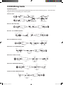
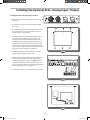
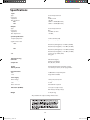
�
��
�
�
�� ���
� �
��
���
��
�
���
������
������
�����
������
����
���
�����
���
������
������
���
DIGITAL DUAL 15 BAND PARAMETRIC EQ /FEEDBACK MANAGEMENT SYSTEM
D3500_ownman_v1_2.indd 1
9/4/05 5:19:53 PM
Safety Instructions/Consignes de sécurité/Sicherheitsvorkehrungen/Instrucciones de seguridad
WARNING: To reduce the risk of fire or electric shock, do not expose this unit to rain
or moisture. To reduce the hazard of electrical shock, do not remove cover or back.
No user serviceable parts inside. Please refer all servicing to qualified personnel.The
lightning flash with an arrowhead symbol within an equilateral triangle, is intended to
alert the user to the presence of uninsulated "dangerous voltage" within the products
enclosure that may be of sufficient magnitude to constitute a risk of electric shock to
persons. The exclamation point within an equilateral triangle is intended to alert the
user to the presence of important operating and maintenance (servicing) instructions
in the literature accompanying the product.
Important Safety Instructions
1. Please read all instructions before operating the unit.
2. Keep these instructions for future reference.
3. Please heed all safety warnings.
4. Follow manufacturers instructions.
5. Do not use this unit near water or moisture.
6. Clean only with a damp cloth.
7. Do not block any of the ventilation openings. Install in accordance with the manufacturers instructions.
8. Do not install near any heat sources such as radiators, heat registers, stoves, or
other apparatus (including amplifiers) that produce heat.
9. Do not defeat the safety purpose of the polarized or grounding-type plug. A polarized plug has two blades with one wider than the other. A grounding type plug has
two blades and a third grounding prong. The wide blade or third prong is provided
for your safety. When the provided plug does not fit your outlet, consult an electrician for replacement of the obsolete outlet.
10. Protect the power cord from being walked on and pinched particularly at plugs,
convenience receptacles and at the point at which they exit from the unit.
11. Unplug this unit during lightning storms or when unused for long periods of time.
12. Refer all servicing to qualified personnel. Servicing is required when the unit has
been damaged in any way, such as power supply cord or plug damage, or if liquid
has been spilled or objects have fallen into the unit, the unit has been exposed to
rain or moisture, does not operate normally, or has been dropped.
ATTENTION: Pour éviter tout risque d’électrocution ou d’incendie, ne pas exposer
cet appareil à la pluie ou à l’humidité. Pour éviter tout risque d’électrocution, ne pas
ôter le couvercle ou le dos du boîtier. Cet appareil ne contient aucune pièce remplaçable par l'utilisateur. Confiez toutes les réparations à un personnel qualifié.
Le signe avec un éclair dans un triangle prévient l’utilisateur de la présence d’une
tension dangereuse et non isolée dans l’appareil. Cette tension constitue un risque
d’électrocution. Le signe avec un point d’exclamation dans un triangle prévient
l’utilisateur d’instructions importantes relatives à l’utilisation et à la maintenance du
produit.
Consignes de sécurité importantes
1. Veuillez lire toutes les instructions avant d’utiliser l’appareil.
2. Conserver ces instructions pour toute lecture ultérieure.
3. Lisez avec attention toutes les consignes de sécurité.
4. Suivez les instructions du fabricant.
5. Ne pas utiliser cet appareil près d’une source liquide ou dans un lieu humide.
6. Nettoyez l’appareil uniquement avec un tissu humide.
7. Veillez à ne pas obstruer les fentes prévues pour la ventilation de l’appareil.
Installez l’appareil selon les instructions du fabricant.
8. Ne pas installer près d’une source de chaleur (radiateurs, etc.) ou de tout équipement susceptible de générer de la chaleur (amplificateurs de puissance par
exemple).
9. Ne pas retirer la terre du cordon secteur ou de la prise murale. Les fiches canadiennes avec polarisation (avec une lame plus large) ne doivent pas être modifiées. Si votre prise murale ne correspond pas au modèle fourni, consultez votre
électricien.
10. Protégez le cordon secteur contre tous les dommages possibles (pincement,
tension, torsion,, etc.). Veillez à ce que le cordon secteur soit libre, en particulier à
sa sortie du boîtier.
11. Déconnectez l’appareil du secteur en présence d’orage ou lors de périodes
d’inutilisation prolongées.
12. Consultez un service de réparation qualifié pour tout dysfonctionnement (dommage sur le cordon secteur, baisse de performances, exposition à la pluie, projection liquide dans l’appareil, introduction d’un objet dans le boîtier, etc.).
ACHTUNG: Um die Gefahr eines Brandes oder Stromschlags zu verringern, sollten
Sie dieses Gerät weder Regen noch Feuchtigkeit aussetzen.Um die Gefahr eines
Stromschlags zu verringern, sollten Sie weder Deckel noch Rückwand des Geräts entfernen. Im Innern befinden sich keine Teile, die vom Anwender gewartet werden können. Überlassen Sie die Wartung qualifiziertem Fachpersonal.Der Blitz mit Pfeilspitze im
gleichseitigen Dreieck soll den Anwender vor nichtisolierter “gefährlicher Spannung”
im Geräteinnern warnen. Diese Spannung kann so hoch sein, dass die Gefahr eines
Stromschlags besteht. Das Ausrufezeichen im gleichseitigen Dreieck soll den Anwender
auf wichtige Bedienungs- und Wartungsanleitungen aufmerksam machen, die im mitgelieferten Informationsmaterial näher beschrieben werden.
Wichtige Sicherheitsvorkehrungen
1. Lesen Sie alle Anleitungen, bevor Sie das Gerät in Betrieb nehmen.
2. Bewahren Sie diese Anleitungen für den späteren Gebrauch gut auf.
PRECAUCION: Para reducir el riesgo de incendios o descargas, no permita que este
aparato quede expuesto a la lluvia o la humedad. Para reducir el riesgo de descarga
eléctrica, nunca quite la tapa ni el chasis. Dentro del aparato no hay piezas susceptibles
de ser reparadas por el usuario. Dirija cualquier reparación al servicio técnico oficial. El
símbolo del relámpago dentro del triángulo equilátero pretende advertir al usuario de
la presencia de “voltajes peligrosos” no aislados dentro de la carcasa del producto, que
pueden ser de la magnitud suficiente como para constituir un riesgo de descarga eléctrica a las personas. El símbolo de exclamación dentro del triángulo equilátero quiere
advertirle de la existencia de importantes instrucciones de manejo y mantenimiento
(reparaciones) en los documentos que se adjuntan con este aparato.
Instrucciones importantes de seguridad
1.
Lea todo este manual de instrucciones antes de comenzar a usar la unidad.
2.
Conserve estas instrucciones para cualquier consulta en el futuro.
3.
4.
5.
6.
7.
3.
4.
5.
6.
7.
8.
9.
10.
11.
12.
Bitte treffen Sie alle beschriebenen Sicherheitsvorkehrungen.
Befolgen Sie die Anleitungen des Herstellers.
Benutzen Sie das Gerät nicht in der Nähe von Wasser oder Feuchtigkeit.
Verwenden Sie zur Reinigung des Geräts nur ein feuchtes Tuch.
Blockieren Sie keine Belüftungsöffnungen. Nehmen Sie den Einbau des Geräts nur
entsprechend den Anweisungen des Herstellers vor.
Bauen Sie das Gerät nicht in der Nähe von Wärmequellen wie Heizkörpern,
Wärmeklappen, Öfen oder anderen Geräten (inklusive Verstärkern) ein, die Hitze
erzeugen.
Setzen Sie die Sicherheitsfunktion des polarisierten oder geerdeten Steckers nicht
außer Kraft. Ein polarisierter Stecker hat zwei flache, unterschiedlich breite Pole. Ein
geerdeter Stecker hat zwei flache Pole und einen dritten Erdungsstift. Der breitere
Pol oder der dritte Stift dient Ihrer Sicherheit. Wenn der vorhandene Stecker nicht in
Ihre Steckdose passt, lassen Sie die veraltete Steckdose von einem Elektriker ersetzen.
Schützen Sie das Netzkabel dahingehend, dass niemand darüber laufen und
es nicht geknickt werden kann. Achten Sie hierbei besonders auf Netzstecker,
Mehrfachsteckdosen und den Kabelanschluss am Gerät.
Ziehen Sie den Netzstecker des Geräts bei Gewittern oder längeren Betriebspausen
aus der Steckdose.
Überlassen Sie die Wartung qualifiziertem Fachpersonal. Eine Wartung ist notwendig, wenn das Gerät auf irgendeine Weise, beispielsweise am Kabel oder
Netzstecker beschädigt wurde, oder wenn Flüssigkeiten oder Objekte in das Gerät
gelangt sind, es Regen oder Feuchtigkeit ausgesetzt war, nicht mehr wie gewohnt
betrieben werden kann oder fallen gelassen wurde.
D3500_ownman_v1_2.indd 2
8.
9.
10.
11.
12.
Cumpla con todo lo indicado en las precauciones de seguridad.
Observe y siga todas las instrucciones del fabricante.
Nunca utilice este aparato cerca del agua o en lugares húmedos.
Limpie este aparato solo con un trapo suave y ligeramente humedecido.
No bloquee ninguna de las aberturas de ventilación. Instale este aparato de acuerdo a las instrucciones del fabricante.
No instale este aparato cerca de fuentes de calor como radiadores, calentadores,
hornos u otros aparatos (incluyendo amplificadores) que produzcan calor.
No anule el sistema de seguridad del enchufe de tipo polarizado o con toma de
tierra. Un enchufe polarizado tiene dos bornes, uno más ancho que el otro. Uno
con toma de tierra tiene dos bornes normales y un tercero para la conexión a
tierra. El borne ancho o el tercero se incluyen como medida de seguridad. Cuando
el enchufe no encaje en su salida de corriente, llame a un electricista para que le
cambie su salida anticuada.
Evite que el cable de corriente quede en una posición en la que pueda ser pisado
o aplastado, especialmente en los enchufes, receptáculos y en el punto en el que
salen de la unidad.
Desconecte de la corriente este aparato durante las tormentas eléctricas o cuando
no lo vaya a usar durante un periodo de tiempo largo.
Dirija cualquier posible reparación solo al servicio técnico oficial. Deberá hacer que
su aparato sea reparado cuando esté dañado de alguna forma, como si el cable de
corriente o el enchufe están dañados, o si se han derramado líquidos o se ha introducido algún objeto dentro de la unidad, si esta ha quedado expuesta a la lluvia o
la humedad, si no funciona normalmente o si ha caído al suelo.
9/4/05 5:19:57 PM
Table of Contents
Introduction
D3500 Features
Controls and Functions
Front Panel Layout
Rear Panel Layout
Setting-up the D3500
Navigating the D3500 Control
Selecting the Input
Using the Left, Right and Link Control Switches
Using the LINK switch
D3500 Quick-start
Using the D3500 to Reduce Feedback
Operating the D3500
Using the Filter Control Knobs
Using the LEARN Mode
Adding Dynamic Filters
Using the Processing Switches
Using the Feed Back Mode
Using the EQ section
Using the Internal Noise GATE
Using the DELAY
Using the ENHANCER
Using the LIMITER for Basic Speaker Protection
Setting an EQ Contour Using the HP / LP
Storing Programs in the D3500
Loading Programs in the D3500
Loading Presets with the MASK function
Using the A/B Feature
MIDI and D Net
Setting the D3500 to Transmit and Receive MIDI
Selecting a MIDI Channel
System Configurations
Using the D3500 with Active Speakers
Using the D3500 with Passive Speakers
Using the D3500 in Insert Points
Using the D3500 for Mains and Monitors
Using Two D3500’s for Mains and Monitors
D3500 Wiring Guide
Installing the Optional AI 02, Analog Input / Output
Specifications
2
3
4
4
5
6
6
6
7
7
8
8
10 - 15
10
11
12
12
12
13
13
14
14
14
15
16
16
16
17
17
17
18
19
19
19
20
20
21
22
23
24
Copyright 2005, Samson Technologies Corp.
Printed May, 2005 v0.1
Samson Technologies Corp.
575 Underhill Blvd.
P.O. Box 9031
Syosset, NY 11791-9031
Phone: 1-800-3-SAMSON (1-800-372-6766)
Fax: 516-364-3888
www.samsontech.com
D3500_ownman_v1_2.indd 1
9/4/05 5:19:57 PM
Introduction
Congratulations! You just purchased one of the most
innovative and useful audio tools available to sound
engineers today, the D3500 Dual 15 Band Parametric
EQ / Feedback Management System. The D3500 is an
advanced parametric equalizer featuring cutting edge
DSP and analog-to-digital conversion technology, together with a simple to use, traditional analog user interface.
The D3500’s robust, 2 rack-space steel and aluminum
extruded chassis design is not only road worthy, but it
also provides a large front panel layout which is extremely easy to use and already familiar to audio engineers.
tion for your loudspeakers. The onboard ENHANCER will
actually add high frequency to the system when there
is program material at those frequencies, adding extra
sparkle to the mix. The ENHANCER will also automatically
turn down the high frequencies when there is no high frequency signal content, eliminating system noise and hiss,
making the D3500 a very effective noise reduction system.
In addition, the D3500 also offers on onboard DELAY for
time aligning speakers. All settings and parameters for
the equalizer and digital effects can be stored in 100 user
pre-set locations. Using the large, easy to read, LCD display and convenient data wheel, it’s possible to save your
favorite equalization curves and recall them in the future.
In addition, the powerful LOAD MASK allows you to recall
certain effects or EQ curves from any preset independently, so you can add pre-set effects settings with real time
changes.
Thanks to the powerful DSP engine and clever software,
the D3500 is capable of producing EQ curves with more
accurate and precise filters, far exceeding the capabilities
of even the best analog equalizers. What you won’t get
is the accumulating additive hiss noise that you get from
an analog equalizer when you add a lot of gain at high
frequency bands. And, with the high-end 24 Bit AD and
DA converters and 96K sampling rate, you’ll enjoy pristine
audio quality.
The D3500 features standard MIDI implementation and
Samson’s D-Net enabling device-to-device linking for creating larger audio systems, for interfacing to a personal
computer. When linking the units you see the full power of
the D-class system. For systems using many D class units,
the D3500 can be fitted with the DN1 D-Net network card.
Samson’s D Net is a high-speed communication protocol
for connected multiple D class units, like the D2500 digital equalizer, D1500 RTA or more D3500s. In addition to
being 10 times faster than MIDI, the error rate is so close to
zero, it’s difficult to measure. All settings and parameters
can be stored in any of the 99 preset locations providing
instant recall of your favorite setups. Like all D class models, the D3500 features an advanced 32-bit point floating
processor DSP interface to high quality converters with
24-bit audio resolution and sample rates up to 96kHz for
pristine audio quality. You can even upgrade your D class
units to premium Analog-to-Digital and Digital-to-Analog
I/O (Input/Output) converter boards, keeping your D class
system up to date with the best technology, and sound,
far onto the future.
The beauty of the D3500 is that while it is a sophisticated, advanced featured parametric equalizer, it can
also work as a one-button automatic feedback management system. For feedback management, the D3500
can employ up to 30 filters for a mono mix, like on stage
monitors, or 2 times 15 bands for stereo PA applications.
The LEARN mode let’s you press a single button and
have the D3500 “ring out” your system automatically (as
if there were a professional monitor mix engineer inside
moving all the knobs for you). You just get a louder PA
with less feedback! The feedback filters work in three
modes; Resonance finds feedback problems inherent in
the room then automatically sets, Dynamic constantly
scan the frequency range looking for feedback problems,
and Manual which are set by using the EQ control knobs.
Plus, the D3500’s feedback filters are intelligent. They
know that often feedback occurs because performers
move around on stage, so the problems can be a temporary ones. Other feedback systems that can destroy your
sound because they just keep cutting more and more
frequency until you’re left with everything cut. Thanks
to the Auto Restore Filter technology, the D3500’s filters
are constantly monitoring the signal and will try to sneak
back to the original positions so that the feedback reduction has a minimum effect on the sound of your mix.
The D3500 is perfectly at home in the studio or on the
road. The fact is, you would use the D3500 equalizer for its
precise filtering and superb audio quality alone, but you
get the power of all the features, and then some, expected
from a high quality digital equalizer. Whether you are a
recordist or a live sound engineer, you’ll get a better sound
using the D3500 Digital Equalizer!
For you “tweakazoids” out there, the D3500 has 30 dedicated switches, which allow you to quickly access the
filters that work together with the physical EQ control
knobs located in the master section. You may forget that
that you are using a digital EQ; simply press a filter button
and grab a knob to tweak the equalizer.
In this manual, you’ll find a detailed description of the
features of the D3500, as well as a guided tour through
the front and rear panels, step-by-step instructions for
using the unit, suggested applications for use with a patch
bay, a Real Time Analyzer (RTA) or for ringing out monitor
systems. You’ll also find a warranty card enclosed—please
don’t forget to fill it out and mail it so that you can receive
online technical support and so we can send you updated
information about other Samson products in the future.
Also, be sure to check out our website (http://www.samsontech.com) for complete information about our full
product line.With proper care and adequate air circulation,
your D3500 will operate trouble free for many years. We
recommend you record your serial number in the space
provided below for future reference.
In addition to being a simple to use feedback management system and digital equalizer, the D3500 is packed
with all the goodies including HIGH & LOW PASS FILTER,
NOISE GATE, LIMITER, ENHANCER and DELAY. All these
digital effects are programmable and their associated
parameters can be stored and recalled, as part of the 100
available user pre-sets. The HIGH and LOW PASS FILTERS
allow you to quickly apply an EQ contour for rolling off
the high and low end frequencies, for example, when
equalizing vocal monitors.
The D3500’s NOISE GATE allows you to set a threshold
level so you can mute any system hums and buzzes during silent sections keeping your system super clean. With
the D3500’s LIMITER you can control the level being sent
to your power amplifiers to help you insure good protec
Serial number:_________________
Date of purchase:_______________
2
D3500_ownman_v1_2.indd 2
9/4/05 5:19:58 PM
D3500 Features
������
������
�����
������
����
���
�����
���
������
������
���
The Samson D3500 Digital Parametric Equalizer / Feedback
Management System utilizes state-of-the-art, DSP and filtering technology for precise tonal and feedback control.
Here are some of its main features:
•
•
•
•
•
•
The D3500 is a sophisticated digital equalizer combined with an advanced, and easy to use, automatic
feedback management system providing 30 bands of
parametric filters.
For stereo PA systems, the D3500 can operate with 15
filter bands per side, or for mono operation (like stage
monitors), you can use all 30 bands at once.
•
To help keep the over all system noise level low, the
D3500 includes a programmable Noise Gate with variable threshold control.
•
An added layer of speaker protection is accomplished
by using the D3500’s programmable brick wall Limiter.
•
The programmable Enhancer can be used to add
extra highs or as a noise reduction system by lowering
the high frequency bands when no high frequency
content is present.
•
The D3500 offers three filter modes, Resonance for
reducing feedback due to room acoustic problems,
Dynamic for feedback problems caused when microphone are moving around on stage, and Manual for
adjusting the parametric filters by hand using the Filter
Control Knobs.
Equalization curves plus all digital effects can be
stored or recalled using the 99 User Preset Locations.
•
Configure larger systems using multiple D class
units which communicate over standard MIDI, or
with Samson’s optional high-speed D-Net interface
card.
For temporary feedback problems like those caused
by microphones moving on stage, a unique AFR, Auto
Filter Release, mode lets the EQ filters gradually restore
themselves to the original levels once the feedback
problem goes away thereby restoring not destroying
your sound.
•
Optional DI01 Digital interface card for connecting to
AES/EBU or S/PDIF.
•
The D3500 takes advantage of the latest technology
with upgradable Analog-to-Digital and Digital-toAnalog converters.
Advanced 32 bit floating point DSP with high-end, 24
Bit, 96K sample rate Analog-to-Digital and Digital-toAnalog converters provides a pristine sound quality
with low distortion and wide dynamic range.
•
Electronically Balanced XLR Inputs and Outputs.
•
Standard 19”, 2 rack-space design for easy integration
into any traveling or fixed installation audio system.
The LEARN mode allows the D3500 to perform a single-button push, automatic feedback reduction system
that will automatically “ring-out” your speaker system
to remove feedback.
•
Aluminum extruded front panel and steel chassis
makes the D3500 eminently road-worthy.
•
Three year extended warranty.
•
An onboard programmable Delay is included for time
aligning speakers.
•
The D3500 offers programmable High and Low Pass
Filters for setting contour curves or for removing lowend stage rumble.
3
D3500_ownman_v1_2.indd 3
9/4/05 5:19:59 PM
Controls and Functions
Front Panel Layout
�
�
�
�
�
�
�
�
�
������
������
��
�����
������
������
����
���
�����
���
������
���
��
��
��
��
��
��
��
��
��
��
��
��
��
��
��
��
��
��
��
1
FILTER SELECT switch – Each of the 30 filters can be
activated and set up by pressing the Filter Select switch.
13 LEFT switch – Assigns the Left (CH1) digital equalizer to the physical controls.
2
DYNAMIC LED – When the Red LED is lit, the filter is set
to Dynamic Mode.
14 LINK switch – Used to control the left and right
(CH1 and CH2) equalizer simultaneously with the
one set of physical controls.
3
RESONANCE LED – Green LED indicating the filter is set
to Resonance Mode.
4
5
6
7
ACTIVE LED – When the Amber LED is lit, the filter is set
to Actice Mode.
16 RESET SWITCH – Used to reset the selected filters
to 0 Gain.
FREQUENCY – Control knob, with LED light-ring position indicator
indicator, used to set the center frequency of the
selected filter from 20 Hz to 20 kHz.
17 FBM (Feedback Managment) switch – Used to
set Sensitivity, Hold and Release for the automatic
feedback filter.
BANDWIDTH – This control knob, with LED light-ring
position indicator
indicator, is used to adjust filter width and can
be set from 1/60th of an octave to 1 octave.
18 EQ switch -- When engaged, the amber LED will illuminate indicating that the EQ parameters are under
control and displayed in the LCD window.
GAIN – Control knob, with LED light-ring position
indicator, used to adjust the gain from +16 dB boost to
indicator
–48dB cut.
8
LEVEL METER - Twelve segment LED meter display the
input level and overload.
9
LCD DISPLAY – Backlit display that shows the various
parameters under control by the operating system.
15 RIGHT switch - Assigns the Right (CH1) equalizer to
the physical controls.
19 GATE switch - Used to access the automatic GATE
control parameters. When selected, the amber LED
will illuminate and the associate values for the digital noise gate will be displayed in the LCD window.
20 DELAY switch - When engaged, the amber LED will
illuminate indicating that the DELAY parameters are
under control and displayed in the LCD window.
10 DATA WHEEL – Rotary encoder for entering parameter
values.
21 ENHANCE switch - When engaged, the amber LED
will illuminate indicating that the ENHANCE parameters are under control and displayed in the LCD
window.
11 BYPASS switch – When the red LED is on, the digital
equalizer, as well as all the on-board digital processing
effects, are defeated.
22 HP / LP switch – LED switch used to access the
HI PASS and LOW PASS control parameters. When
selected, the amber LED will illuminate and the
associated values for the high and low pass filters
will be displayed in the LCD window.
12 A / B switch – Used to switch between your modified
program, and the last program that has been loaded or
stored into memory.
4
D3500_ownman_v1_2.indd 4
9/4/05 5:20:01 PM
Controls and Functions
23 LIMITER switch – This switch is used to page
through the LIMITER parameters. When
selected,the amber LED will illuminate and the
LIMITER parameters will be displayed in the LCD
window.
26 GLOBAL switch – When engaged, the red LED will
illuminate indicating access to the unit's GLOBAL
parameters.
27 MIDI switch - This switch is used to page through
the MIDI parameters. When selected, the red LED
will illuminate and the MIDI parameters will be displayed in the LCD window.
24 IN / OUT switch – The LED switch is used to
engage the FEEDBACK, GATE, DELAY, ENHANCER
and LIMITER effects. When one of the aboves
effects switch is selected, (for example FEEDBACK),
that effect is turned on when the IN / OUT amber
LED is illuminated.
28 LOAD switch – Used to load one of the 100 programs from the internal memory.
29 STORE switch - Used to store one of the 99 programs into the internal memory.
25 LEARN switch – When selected, the Automatic
Feedback system will engage and the unit will
automatically ring-out the speaker system.
Rear Panel Layout
�
�
�
�
�
�
�
�
A
POWER SWITCH – When set to the ON position, the
D3500 is powered up and ready for operation.
B
MIDI IN DIN connector – The D3500 receives standard, or
system exclusive, MIDI data here.
C
D
E
I/O Accessory Blank Panel – Removable blanking panel
accesses option bay for adding additional Analog-to
Digital or Digital Input/Output boards.
F
AC input fuseholder - Connect the supplied heavy
gauge 3-pin “IEC” power cable here.
G
DNET Accessory Blank Panel – Removable blanking
panel accesses option bay for adding the DNET interface
card for control multiple D class units.
�
�
H
CH1 Balanced XLR jack input - Electronically
balanced XLR jack input. Wiring is as follows: pin 2
hot, pin 3 cold, and pin 1 ground.
I
CH2 Balanced XLR jack input - Electronically balanced XLR jack input.
MIDI OUT DIN connector - The D3500 transmits standard,
or system exclusive, MIDI data here.
J
MIDI THRU DIN connector - The D3500 passes standard,
or system exclusive, MIDI data here.
�
K
CH1 Balanced XLR jack output - Electronically
balanced XLR jack output.
CH2 Balanced XLR jack output- Electronically
balanced XLR jack output.
5
D3500_ownman_v1_2.indd 5
9/4/05 5:20:03 PM
Setting-up the D3500
RIGHT which are used to assign the D3500's hardware
controls to operate the Left, Right or Left and Right EQ
channels. RESET is the next switch and it allows you
quickly clear any selected filters, returning them to the 0dB
Gain position. The next section is where you will find the
D3500’s powerful onboard digital loudspeaker processing
effects, which are controlled by the FBM, EQ, GATE, DELAY,
ENHANCE, HP /LP, LIMITER and IN/OUT switches. GLOBAL
gives you access to the overall system settings, and MIDI
lets you set up the device-to-device communications
including Samson Audio’s high-speed, D-Net protocol.
Finally, in order to save and retrieve your favorite settings,
the D3500’s LOAD and STORE switches allow you to access
the 100 on-board presets. The following sections of this
manual will detail each of the switches and their associated parameters. Instead of going from left to right, we’ll
switch up the order a bit for a more logical flow through
the system.
SETTING UP THE D3500
Setting up your D3500 Graphic Equalizer is a simple procedure which takes only a few minutes:
1. Remove all packing materials (save them in case of
need for future service) and decide where the unit is to
be physically placed—it can be used free-standing or
mounted in a standard 19" rack.
2. Make sure the power to all mixers and amplifiers in
your audio system is off.
3. The D3500 can be used either as an “in-line” device,
as an insert device (in conjunction with mixer insert
points), or in an effects send-return loop. The illustrations on pages 19-21 show each of these typical configurations. Choose the configuration that is best for
your application and then begin by making the D3500
input connections, using the XLR connectors on the
rear panel.
You should know this !
Some switches are capable of accessing more than one
parameter, so as you press the switch repeatedly you will
page through the available parameters. These include the
FBM, GATE, HP/LP, Limiter, GLOBAL and MIDI. For example,
the FMB switch has three pages to click though the parameters, Sensitivity, Feedback Hold, Feedback Release. You
can change the parameters of any of these functions by
using the large Data Wheel located by the main LCD display.
4. Next, make the D3500 output connections, using the
XLR connectors on the rear panel to connect your
power amplifier or active speakers.
5. Plug in the supplied AC cord and connect it to any
standard AC socket.
6 . Press the rear panel Power switch to turn on the
D3500. Press the Filter Select switches in to activate
the equalizer.
GLOBAL
The GLOBAL control allows you to set up the various system parameters including the input option and mode.
Note: if you have the AI02 board installed, the audio signal
will be muted for approximately five seconds until the relay
power-on circuitry is activated (at which time you’ll hear a
click and the audio signal will be unmuted).
The Global Switch Has Two Clicks!
Click Menu Function
Value
1
Inp. Input
Opt 1, Opt 2
2
Md. Mode
Stereo, Dual
Navigating the D3500 Control
Before you move ahead into the many D3500 onboard
effects, you should become familiar with the front panel
controls and the various parameters that they can set.
The D3500 front panel switches are set up in groups related to the function or parts of the operating system they
control. Some switches are placed individually, since they
are dedicated to a single function, and other switches are
arranged in groups since their functionality is related. The
D3500 function switch sections are arranged on the front
panel as follows. First, is the BYPASS switch that enables
you to turn the equalizer and all effects on or off. Next is
the A/B switch that lets you compare the actual modified
program to the last program loaded or stored . Then you
will find a group of switches including LEFT, LINK and
Selecting the Input
The D3500 accepts inputs from any of the installed I/O
boards including the optional DIO1 Digital I/O or AIO2,
premium analog-to-digital I/O board. The D3500 automatically senses if a board is installed in an option slot. To
access the input follow these steps:
6
D3500_ownman_v1_2.indd 6
9/4/05 5:20:04 PM
Setting-up the D3500
If you want to use the D3500 as a dual mono equalizer and
control the Left and Right sides individually, keep the LINK
switch OFF so that the green LED is not lit.
• Press the GLOBAL control switch once or twice until you
see the Inp.
Controlling the Right Channel signal
If you want to control the EQ and the effects for the right
channel individually, make sure the LINK switch is OFF.
Now, press the RIGHT switch to assign the hardware control surface to the signal connected to the right channel.
With the RIGHT switch selected on and the LINK switch off,
the D3500 controls will edit just the right channel filters
and right channel parameters when accessing the various
menus.
Use the Data Wheel to select OPT 1 or OPT 2.
NOTE: Once you make an edit to the Global set-up, the red
GLOBAL LED will flash indicating that a change has been
made to the original set-up. You will also see that the red
STORE LED is illuminated.
Controlling the Left Channel signal
If you want to control the EQ and the effects for the left
channel individually, make sure the LINK switch is OFF.
Now, press the LEFT switch to assign the hardware control
surface to the signal connected to the left channel. With
the LEFT switch selected on and the LINK switch off, the
D3500 controls will edit just the left channel filters and left
channel parameters when accessing the various menus.
• To keep the new changes, press the STORE button and
you will exit the GLOBAL mode and both the STORE and
GLOBAL LED’s will turn off.
Using the Left, Right and Link Control Switches
Since the D3500 is a two-channel unit, you can use it as
a stereo, or dual mono equalizer if you are running two
monitor mixes. Depending on the operating mode you set
up in the Global menu, you may want to have the left and
right channels operate together, or individually. The LEFT,
RIGHT and LINK switches will help you operate the D3500
easily and give you the control you need to quickly make
changes and control either one or both sides. The state of
these switches will determine which of the left and right
signals are affected by the hardware control surface and
which channel's parameters are diplayed in the LCD.
Keep in mind that the LEFT or RIGHT switch determines
which channel's parameters are displayed in the LCD.
Therefore, even if the LINK is on, you can still use the LEFT
and RIGHT switches to select which sides parameters are
displayed in the LCD. This becomes important if you set
the Left or Right channel to a different parameter and then
link them. For example, it is possible to set the same filter
setting for both sides using LINK, then unlink and change
the Gain of one filter on one side. If you press the LINK
again the hardware will control both sides, however the
GAIN will be offset. You can see this by using the LEFT and
RIGHT switches when LINK is on.
Using the LINK switch
If you want to set the D3500 so that the phyiscal hardware
controls and all the parameter controls adjust both the
Left and Right side, press the LINK switch so that the green
LED is lit. Now, when you operate any of the controls, either the EQ control knobs or the digital effects, you will be
making the same change on the left and right sides.
7
D3500_ownman_v1_2.indd 7
9/4/05 5:20:05 PM
D3500 Quick-start
Quick start – Using the D3500 to Reduce Feedback
The D3500 is a powerful 30 band, fully parametric equalizer with onboard loudspeaker processing effects. Each
of the 30 filters can be manually set and all the effects
parameters can be adjusted and stored into memory.
However, if you want to use the D3500 as a simple automatic feedback management system, you can. First, lets
look at some basic concepts to employ that will help
reduce the chance of feedback before you even power up
the D3500.
ter, you’ll set some additional filters to DYNAMIC mode to
handle feedback problems that occur from artists moving
around on stage with their microphones. When the filter is
set to DYNAMIC mode, it will search for feedback and then
lock on that frequency until the feedback problem goes
away. If the filter set to DYNAMIC senses that the feedback problem is no longer present, it will begin to search
for new feedback problems. So, by setting some filters to
Resonance and some to Dynamic, you can easily handle
feedback problems from speaker and mic placement, as
well as from presenters and performers moving around
with live mics. Simply follow these basic steps and start
getting a louder mix without feedback.
Microphone Positioning - How to Reduce Feedback
Feedback is the annoying howling and squealing that is
heard when the microphone gets too close to the speaker
and the volume is high. You get feedback when the microphone picks up the amplified signal from the speaker, and
then amplifies through the speaker again, and then picks
it up again, and so on and so on. In general, it is always
recommended that any LIVE mic (a mic that’s on) is positioned behind the speaker enclosures. This will give you
the best level from your system before feedback. One
possible exception is when you are adjusting the sounds
of the microphones, since you want to listen in front of the
speaker to hear properly. To do this, lower the PA system' s
main volume while setting the EQ and effects from in front
of the speakers. Once you have the sound you like, move
the microphones to behind the speakers and raise the
Main volume. In addition, be aware of your microphone's
pick up pattern. For most live sound applications, a unidirectional or Cardioid microphone with great rear rejection is the best solution for getting the most gain before
feedback. Looking for a great dynamic mic with above average feedback rejection? Try a Samson Q7.
• Using standard XLR cables, connect the output of your
mixer to the D3500's rear panel XLR INPUT connectors.
• Now, run another set of XLR cables and plug the D3500's
rear panel XLR OUTPUT's to your power amp or active
speaker inputs.
Note: If you are using any other signal processors like a
graphic equalizer or compressor, put the D3500 after them in
the signal path.
• Power up your system as normal.
• Press the D3500's LINK switch so that the green LED
lights, indicating the left and right channels are linked
together.
• Press the BYPASS switch so that the LED is off, indicating
the D3500’s digital processing effects are engaged.
Speaker Placement
Whenever possible, it is a good idea to raise the speakers
above the heads of the listening audience. Any good loudspeaker, like the Samson dB500, Expedition, or Resound
model enclosures, feature a standard 1 3/8” pole mount
receptacle, which is compatible with speaker stands from
a variety of manufacturers (including the Samson TA100).
Position your speakers for the best audience coverage, but
be aware of where your live mics will be during the course
of your performance or presentation and position the
speakers in front of the live stage area.
• You’ll probably want to start with a default preset, so
press the LOAD switch. The LED will flash indicating the
D3500 is ready to load a preset.
• Use the Data Wheel to select Preset 00 and press LOAD.
• Now, select the first ten filters by pressing and holding
the Channel 1 Filter Select Switch, and then press the
Channel 10 Filter Select Switch. At this point you will
notice that the green Selection LEDs for the filters 1 – 10
are lit. This indicates that the filters are ready to be setup and engaged.
Using the D3500 for Automatic Feedback Managemet
The following example is for reducing feedback in a typical PA system used by a band in a small to medium size
club using the D3500. First you’ll set ten of the filters to
RESONANCE mode to remove problem frequencies that
occur due to microphone and monitor placement, as well
as those caused by room acoustics. When the filters are set
to Resonance the D3500 will detect a feedback problem,
then set automatically the filter to the feedback frequency,
and then lock on that frequency until it is reset or a new
program is preset loaded. After setting the RESONANCE fil-
• To set these filters to RESONANCE mode press the EQ
switch until MODE is displayed in the main LCD.
• Use the Data Wheel to select Mode 3; (RESONANCE).
8
D3500_ownman_v1_2.indd 8
9/4/05 5:20:06 PM
D3500 Quick-start
• Now, select filters 11 through 15 by pressing and holding the Channel 11 Filter Select Switch, and then press
the Channel 15 Filter Select Switch. At this point you will
notice that the green Selection LEDs for the filters 11
– 15 are lit. This indicates that the filters are ready to be
set-up and engaged.
• To set these filters to DYNAMIC mode, press the EQ
switch until MODE is displayed in the main LCD.
• Use the Data Wheel to select Mode 2; (DYNAMIC).
Now, you run your sound system as normal and try to
manually ring out your system by raising the main volume
just at the point of feedback. You'll see the D3500's front
panel LEDs lighting as it responds to the feedback using
the RESONANCE filters. You will know when a filter is
active when the filter's ACTIVE light goes on. Now, during
your performance you'll see the D3500's front panel LED
lighting as it reacts to any occurrence of feedback using
the DYNAMIC filters. Again, when the DYNAMIC filter is
engaged you will see that filter's ACTIVE LED light. Don't
be concerned if all the filters do not activate. Since the
D3500 is truly smart and knows what it is doing, it will only
use the number of filters necessary to do the job. By following the simple procedure, and without even tapping
into the powerful parameters of the D3500, your system
should be noticeably louder.
Filter Mode Chart
O = OFF
1 = MANUAL
2 = DYNAMIC
3 = RESONANCE
9
D3500_ownman_v1_2.indd 9
9/4/05 5:20:06 PM
Operating the D3500
Using the Filter Control Knobs
The D3500’s front panel features a hardware control section with encoder knobs that allow you to make quick
real time adjustments to FREQUENCY, BANDWIDTH and
GAIN for any of the 30 filters. You can adjust any filter that
has been set by an internal preset using the Filter Control
Knobs. You can also operate a filter in MANUAL mode and
use the Filter Control Knobs to quickly set the EQ band by
hand, and by ear.
• Press the LINK switch so that the green LED lights,
indicating the left and right channels are linked
together.
Since each of these filter parameters can be set manually
or by recalling a preset from the internal memory, the
parameters can change quickly so you’ll need to know
how the new filter parameters are set. To handle this problem, the D3500’s filter control knobs have LED light rings
around the encoders, which when lit, indicate the position
of the filter parameters. This gives you a graphical representation of the how the equalizer band would look on a
traditional analog parametric eq.
• To set these filters to MANUAL mode, press the EQ
switch until MODE is displayed in the main LCD.
• Select the active filters by pressing the Channel 1
Filter Select Switch. At this point you will notice that
the green Selection LEDs for filter 1 is lit on both
channels. This indicates that the filters are ready to be
set-up and engaged.
• Use the Data Wheel to select Mode 1; (MANUAL).
• Now, simply move the GAIN knob and you'll see the
�����
������
�� �
� �
��������
�����
��
ACTIVE LED for the selected filters light up indicating
the filters are engaged. You will also notice that GAIN
and the associated value now appear in the LCD window.
•
It’s easy to assign any filter to the encoder knobs by simply
pressing any of the Filter Selection buttons. Follow the
simple steps below to set a filter to Manual and then use
the Filter Control Knobs to adjust the band.
Next, you can use the FREQUENCY knob to set the
center frequency of the filter, which can be adjust
from 20 Hz - 20 kHz. When you adjust the knob you
will see FREQUENCY and the associated value in the
LCD window.
• Press the BYPASS switch so that the LED is off, indicating the D3500’s digital effects are engaged.
• You will probably want to start with a default preset,
so press the LOAD switch. The LED will flash indicating
the D3500 is ready to load a preset.
• Now, you can experiment by changing the filter
BANDWIDTH from 1/60th of an octave to 10 octaves.
When you adjust the knob you will see BANDWIDTH
and the associated value in the LCD window.
• Use the Data Wheel to select Preset 00.
Note: Preset 00 is a factory default set up that CANNOT be
overwritten.
Note: You can quickly return one or more selected filters back
to a GAIN of 0 dB by pressing the RESET switch. Be sure that
the green LEDs on the Filter Select switches for the filters that
you want to return to 0 dB are lit, then press RESET.
10
D3500_ownman_v1_2.indd 10
9/4/05 5:20:07 PM
Operating the D3500
• Use the Data Wheel to select Mode 3; (RESONANCE).
Using the LEARN Mode
The following example is for reducing feedback in a typical
PA system used by a band in a small to medium size club
using the LEARN feature. You will set ten of the filters to
RESONANCE mode to remove problem frequencies that
have to do with microphone and monitor placement, as
well as room acoustics. Later on in this section, you will
find an example that explains how to set some additional
filters to DYNAMIC mode to handle feedback problems
that occur from artists moving around on stage with their
microphones. To get started with the LEARN function follow these simple steps:
�����
������
�� �
� �
��������
�����
��
• Next, adjust your microphones to the maximum volume, just before feedback. It's actually a good idea to
let a little bit of feedback ring out, and then turn the
level down just below the feedback.
• Press the LINK switch so that the green LED lights,
indicating the left and right channels are linked
together.
������
������
• Press the BYPASS switch so that the LED is off, indicating the D3500’s digital effects are engaged.
• Now press the LEARN switch.
• To recall a default preset, press the LOAD switch. The
LED will flash indicating the D3500 is ready to load a
preset.
• Use the Data Wheel to select Preset 00.
• Press the LOAD switch again. The LED will stop flashing indicating the preset has been loaded.
• Next, turn the data wheel to select "Start : yes", press
start and watch and listen to the D3500 ring out the
monitors.
• Now, select the first ten filters by pressing and holding the Channel 1 Filter Select Switch, and then press
the Channel 10 Filter Select Switch. At this point you
will notice that the green Selection LED for the filters
1 – 10 are lit. This indicates that the filters are ready to
be set-up and engaged.
The red LED in the LEARN switch will flash indicating that
the D3500 is scanning the frequency range and adjusting the filters automatically to reduce feedback, allowing
you to maximize the overall system level. You can see the
filters being set one-by-one by looking at each Filter's
mode LED. As a filter sets itself, the ACTIVE LED will light
up. You can also watch the LED’s around the FREQUENCY,
BANDWIDTH and GAIN control knobs change as the filter
is setting. Once the D3500 completes the filter scan, the
red LEARN LED will stop flashing, letting you know that
the LEARN function is completed. In some situations, all
the filters may not set. This is okay, since the D3500 will
only use what it needs to get the job done, and is always
intelligently managing the internal DSP resources in order
to maximize system performance.
• To set these filters to RESONANCE mode press the EQ
switch until MODE is displayed in the main LCD.
Now, you can add some DYNAMIC filter to handle the problems caused by artists moving around the stage with active
microphones. Follow the next section to set the Dynamic
filters.
11
D3500_ownman_v1_2.indd 11
9/4/05 5:20:08 PM
Operating the D3500
Adding Dynamic Filters
• If you have not set the RESONANCE filters to remove
feedback problems that occur due to microphone and
monitor placement, as well as room acoustics it is a good
idea to do so by following the previous section, “Using the
LEARN Mode”, to set filters 1 - 10.
Using the Processing Switches
In addition to being a great sounding, clinically precise,
digital equalizer, the D3500 provides a host of useful digital effects, which have been designed to make an audio
engineer’s job easier and project sound better. The MODE
switch lets you set the operating parameter for the automatic feedback filters. The EQ switch assigns the selected
digital eq filter to the LCD screen so you can view a numeric measurement of the Frequency, Bandwidth and Gain.
• Next, select the filters number 11 – 15 by pressing and
holding the channel 11 Filter Select Switch, and then
press the channel 15 Filter Select Switch. At this point
you will notice that the green Selection LED for the filters 11 – 15 are lit. This indicates that the filters are ready
to be set-up and engaged.
The GATE effect allows you to eliminate annoying buzzes
and hums. The DELAY effect is perfect for phase aligning
speakers systems using multi-transducers and for delaying speaker arrays in large venue installations. The D3500’s
unique ENHANCER effect will help reduce the overall system noise, while at the same time, sweeten-up the high
end of any speaker. To set the over all low or high-end
frequency contour, the D3500 features multi-pole, Hi-pass
and Low-pass filters. Speaker protection is handled with
the D3500’s digital LIMITER.
The navigation buttons located in the center of the unit
under Filter Select buttons, along with the Data Wheel,
control the various parameters used to set-up these powerful effects. Remember, some of the effects may have
several pages, which are accessed by pressing through the
effects switches.
To set these filters to DYNAMIC mode, press the EQ
switch until MODE is displayed in the main LCD.
• Use the Data Wheel to select Mode 2; (DYNAMIC).
• Now you can see how the filters work by taking a microphone and performing a walk test around the stage.
�����
������
�� �
� �
��������
�����
��
Using the Feed Back Mode
You can adjust the parameters of the automatic feedback
filters in order to optimize the performance for your specific application by using the D3500’s Feedback Mode setup. The D3500 let’s you adjust the Sensitivity, Release time
and Hold time for the automatic filters. Follow these steps
to adjust the Feedback Mode.
When you step in front of a monitor, and it feeds back,
you will see the ACTIVE LED of one of the Filters set to
DYNAMIC light, indicating that filter is setting itself. As
you continue to walk and get more feedback the other
filters will set themselves.
• Note: You can clear out any filter (or number of filters)
and have it start search for the feedback frequency
again by pressing the Filter Select switch and the pressing the RESET switch.
12
D3500_ownman_v1_2.indd 12
9/4/05 5:20:10 PM
Operating the D3500
• To access the Feedback Sensitivity parameter, press the
FBM switch until you see the menu, FBM: Sensitivity.
The Feedback Sensitivity is used to set the threshold
that the D3500 uses to recognize feedback. Now you
can select a Sensitivity of 0 – 10. This parameter affects
both the Resonance and Dynamic filters.
• To access the Feedback Hold Time parameter, press
the FBM switch until you see the menu, FB: Hold. The
D3500’s Feedback management system uses HOLD time
to keep a filter cut after the system identifies feedback.
Now you can select a Hold time of 0 – 10. This parameter affects only the Dynamic filters.
• To access the Feedback Release Time parameter, press
the FBM switch until you see the menu, FB Rel.. Now
you can select a Release time of 0 – 10. If the feedback is
temporary, the D3500 will attempt to restore the fader
back to the original position. The Release time is the
time the D3500 takes to return the fader back to the
original level. This parameter affects only the Dynamic
filters.
• Select the active filters by pressing the Channel 1 Filter
Select Switch. At this point you will notice that the
green Selection LED for filter 1 is lit on both channels.
This indicates that the filters are ready to be set-up and
engaged.
• Press the EQ switch until the yellow LED is lit. Be sure
that the EQ IN switch is Illuminated .
• Press the EQ switch a few times until it reads; Mode.
• Use the data wheel to select Mode 1 (Manual).
• Now, use the FREQUENCY control knob and LCD display
to adjust the filter center frequency to 250 Hz.
• Next, use the BANDWIDTH control knob and LCD display to adjust the filter bandwidth frequency 20/60
octave, or 1/3 octave.
• Now,
Now turn the GAIN control knob counter clockwise,
while watching the LCD display and adjusting the gain
frequency to -48 dB.
Note: You can page through the various parameters under
the EQ section, however you can only make edits to Gain,
Frequency and Bandwidth when the filter is set to the Manual
(1) operating mode.
Using the Internal Noise GATE
The D3500 digital effect section includes a digital noise
gate that can be very useful in eliminating the system
hums and buzzes that may occur, especially when you are
using your system in different venues. A noise gate is a
powerful dynamics processor that works like an automatic
mute. Simply put, when the desired signal is present, the
gate is open and the sound can be heard. When the signal
is soft, like when the music stops, and all that's left are the
hums, buzzes and system noise floor, the gate is closed.
The D3500 GATE has variable control over Threshold and
Release time. Threshold is the level you set at which the
noise gate will close (mute the sound). You want to set a
level in between the noise floor and the normal operating
level of your program. Release Time is the amount of time
the D3500’s Gate takes to reduce the signal to off after the
signal falls below the Threshold level.
The EQ Switch Has Four Clicks!
Click Menu
Function
1
Mode
Filter Mode
The Noise Gate Switch Has Two Clicks!
Click Menu
Function
1
Gate Rel.
Release Time
Using the EQ section
You can control any of the 30 bands of parametric eq manually by using the Filter control knobs and the EQ function. While using the EQ, is possible to set the operational
characteristics of the filter to any of four modes. Bypass,
no filter at all. Manual, which lets you set a filter like an
analog parametric equalizer. When set to Dynamic mode,
the filter is floating and will reset itself to adjust to changing feedback problems. Resonance for system and room
acoustic problems, the filters set automatically to remove
feedback and stay set to that frequency .
2
3
4
Value
1 (Manual),
2 (DYNAMIC),
3 (RESONANCE)
Frequency Filter Center Freq. 20 Hz - 20 kHz
Bandwidth Filter Bandwidth 1/60th - 10 Octaves
Gain
Filter Gain
-48 dB - +16 dB.
The following example explains how to set a filter to a specific Frequency, Bandwidth and Gain. We'll set a 1/3 octave
filter with -48 dB of cut at 250 Hz.
• Press the LINK switch so that the green LED lights, indicating the left and right channels are linked together.
D3500_ownman_v1_2.indd 13
2
Gate Th.
Threshold Level
Value
0 - 100 % (2 to
15 sec.)
0 - -100 dB
To operate the D3500 digital noise GATE, follow these
simple steps:
• Press the GATE switch so that the yellow LED is lit.
• Now, engage the effect by pressing the IN / OUT switch
until the yellow LED lights.
13
9/4/05 5:20:11 PM
Operating the D3500
Once the highs return, the Enhance releases automatically.
Of course the D3500 lets you dial up just the right amount
of Enhancer for your project, so follow the steps below to
activate the Enhancer.
• To access the Threshold parameter, press the GATE
switch until you see the menu, Gate Th. The Gate
Threshold can be set from –100 dB to 0 dB.
• To access the Release parameter, press the GATE switch
until you see the menu, Gate Rel. The Gate Release time
can be set from 50 to 100 % (equivalent to 2 to 15 seconds).
�����
������
� ��
� ��
• Press the ENHANCE switch so that the yellow LED is lit.
• Engage the effect by pressing the IN / OUT switch until
the yellow LED lights.
• Now, use the Data Wheel to select the correct Enhancer
setting, from 0 to 100%, that’s right for your application.
��������
�����
�����
Using the DELAY
The D3500 offers an on board Digital Delay for setting up
delay clusters in large venue sound systems. The Delay
can be set from 0 to 85 milliseconds. Setting the delay is
a simple procedure which can be accomplished by following the next few steps:
������
• Engage the effect by pressing the IN / OUT switch until
the yellow LED lights.
• Now, use the Data Wheel to select the correct delay
time for your application.
�����
������
��
��
������
��������
�����
Setting an EQ Contour Using the HP / LP
The D3500 includes digital High-pass and Low-pass filters
for creating quick equalization curve contours. A Hi-pass
filter, sometimes called a low-cut filter, is used to attenuate
the frequencies below are certain point. The HP filter passes the highs, but cuts the lows. A Low-pass filter, sometimes referred to as a high-cut filter, is used to attenuate
the frequencies above a certain frequency point. The LP
filter passed the lows, but cuts the highs.
• Press the DELAY switch so that the yellow LED is lit.
Using the ENHANCER
� ��
� ��
You can use the High and Low pass filters for a variety of
applications. Using the High-pass filter can be especially
useful in removing the low frequencies that can some
times cause stage rumble. If you have a lot of high frequency system noise and hiss, you can use the Low-pass
filter to roll-off the high-end of your system. When equalizing a monitor system, you may use both the HP and LP
filters to roll-off the high and lows for a vocal eq contour.
��
The D3500 has a unique digital Enhancer, which can help
sweeten a sound system, and at the same time, reduce
unwanted noise. The D3500’s Enhancer uses several
powerful algorithms to analyze the signal content and
then decide how to enhance the signal; based on that
content. If the D3500 Enhancer senses that there is music
playing with good high frequency content, it will slightly
boost these frequencies creating sweet and airy top-end
response. When the D3500 Enhancer sees that there is little or no high-frequency content, it will slightly reduce the
high-frequency response of the system. This can be especially useful since often when the high-frequency content
is very low, or off, the only thing you hear is system hiss.
The Enhancer will recognize the noise and reduce it by
cutting the associated EQ filters automatically.
Any good high and low-pass filters will allow you to
choose the cut-off frequency, and also, the Order, or slope,
at which the filter will attenuate. The D3500 let’s you set
the frequency at which the HP or LP filters cut from, and
they will also let you choose slope of either 6, 12 or 18 db
per octave.
14
D3500_ownman_v1_2.indd 14
9/4/05 5:20:12 PM
Operating the D3500
The HP / LP Switch Has Four Clicks!
Click Menu
Function
Value
1
Lowpass high Cut Filter 2 kHz - 20 kHz
2
Lp-Order Filter Slope
0, 6, 12, 18 per Octave
3
Highpass low Cut Filter 20 Hz - 200 Hz
4
HP-Order Filter Slope
0, 6, 12, 18 per Octave
Using the LIMITER for Basic Speaker Protection
In order to help you protect your speaker system, the
D3500 employs a digital Limiter. When engaged, the
digital Limiter will prevent signals from reaching outputs
levels over a desired point. The D3500’s Limiter has a variable Threshold level, which is the point the limiter circuit
begins to attenuate the system. The Limiter also has a
variable Release time, which is the time the limiter circuit
takes to return the signal to the original level.
• Press the HP / LP switch so that the yellow LED is lit.
• Engage the effect by pressing the IN / OUT switch
until the yellow LED lights.
The LIMITER Switch Has Two Clicks!
Click Menu
Function
Value
1
Lim. Thr.
Threshold
0 to -100 dB
2
Lim. Rel.
Release Time
50 to 100 % (equiv
alent to 2 to 15 seconds)
• To set the High-pass filter press the HP / LP switch
until the LCD display reads; High-pass.
• Now, use the Data Wheel to set the frequency from 20
Hz to 200 Hz.
�����
������
� ��� �
� ��� �
�����
To operate the D3500 digital LIMITER follow these simple
steps.
��
• Press the LIMITER switch so that the yellow LED is lit.
• Now, engage the effect by pressing the IN / OUT
switch until the yellow LED lights.
• Press the HP / LP switch again and you will see the
menu to set filter Order, or slope. The menu will read
HP-Order.
• To access the Threshold parameter, press the LIMITER
switch until you see the menu, Lim. Th. The LIMITER
Threshold can be set from –100 dB to 0 dB.
• Use the Data Wheel to choose a slope of either 6dB,
12dB, or 18 dB.
• To access the Release parameter, press the LIMITER
switch until you see the menu, Lim. Rel. The LIMITER
Release time can be set from 50 to 100 % (equivalent
to 2 to 15 seconds).
Note: If you want to use the Low Pass filter but not the High
Pass filter set the Low Pass filter slope to 0 dB.
• To set the Low-pass filter, press the HP / LP switch
until the LCD display reads; Low-pass.
�����
������
• Now, use the Data Wheel to set the frequency from 20
Hz to 20 kHz.
� � ��
� � ��
��
��
• Press the HP / LP switch again and you will see the
menu to set filter Order, or slope. The menu will read
LP-Order.
• Use the Data Wheel to choose a slope of either 6dB,
12dB, or 18 dB.
Note: If you want to use the High Pass filter but not the
LowPass filter set the High Pass filter slope to 0 dB.
15
D3500_ownman_v1_2.indd 15
9/4/05 5:20:12 PM
Operating the D3500
Storing Programs in the D3500
The D3500 has 99 memory locations (labeled 01-99) for
storing user presets. You can save the equalization curve,
as well as all the parameters for the routing and the
onboard effects that may be active. Saving the preset is a
simple procedure which is accomplished with the following easy steps.
Using the Load MASK function
The D3500 allows you to mask certain saved parameters
when loading in a preset. This is a powerful feature that
allows you to create a new preset by merging different
saved equalization curves with other saved effects set-ups.
When you get deeper into the features of the D3500, there
may be many parameters to set to create your final sound.
A “hidden” feature in the D3500 is the Set Mask function.
This allows you to load other programs and “Mask Out”
(retain) certain parameters.
• Press the STORE button and the LED will begin to
flash indicating that the D3500 is ready to store the
current set-up into one of the 99 memory locations.
Example:
In your overall setup, you have a delayed stack of speakers
on the left side with a setting of 40mS. You have your limiter
set to +2dB to not overdrive your amps, and your subs are
being crossed over to a different amplifier. So from 80Hz on
down, you set a High Pass filter so that the Bass is not passing
through the D3500 to the delayed stack.
• Now, you need to decide if you want to save the setup in the current memory location, or if you want to
choose a new memory location. If you want to use the
current location, go on to the next step. If you want to
choose a new memory location, use the Data Wheel
to scroll through the 99 preset numbers until you
reach the number you want to save under.
Lets say you want to load program #2 one hour into the
show, ( a slightly hotter EQ curve that you stored in memory location #2 before the show began for use when the
room fills up).You want to change the EQ curve but you do
not want to load in the program #2’s Delay, HP, and Limiter
settings.
• Once you select the program number to save under,
simply press the STORE button again and your set up
is saved and can be easily recalled using the LOAD
function.
��
• Press and hold Store.
Loading Programs in the D3500
You can load presets with stored equalization curves, as
well as all the parameters for the routing and the onboard
effects that may have been used. Loading a preset is a
simple procedure, which is accomplished with the following easy steps.
FBM, EQ, GATE, DELAY, ENHANCE, HP/LP, LIMITER, AND IN/
OUT will light.
• Press Delay, HP/LP, and Limiter and their respective LED’s
will go out.
• Press the LOAD button and the LED will begin to flash
indicating that the D3500 is ready to load one of the
99 memory locations.
• Now when you load any other program, you will
retain your Delay, HP/LP, and Limiter settings. Only the
Parameters not “Masked” will load from the second program loaded..
• Now, you need to decide if you want to load the setup in the current memory location, or if you want to
choose a preset saved in a different memory location.
If you want to use the current location, go on to the
next step. If you want to choose a new memory location, use the Data Wheel to scroll through the 99 preset numbers until you reach the number you want to
recall into memory.
• Once you select the program number to load, simply
press the LOAD button again and your preset is loaded
into memory.
16
D3500_ownman_v1_2.indd 16
9/4/05 5:20:13 PM
Operating the D3500
MIDI and D Net
For expanded system control, the D3500 uses standard
MIDI, as well as Samson’s D Net communication protocols,
to transmit and receive digital control information to and
from additional D class units, other MIDI devices, or personal computers. You can use standard MIDI cables for
IN, OUT and THRU to configure a system using traditional
MIDI protocol. If higher speed communication is needed,
you can install the optional DN1, D-Net interface cards
and use standard XLR cables to configure a high-speed,
bi-directional data hook-up using Samson D-Net protocol.
The MIDI and D-Net control parameters are configured by
accessing the various menus with the MIDI switch, located
on the D3500’s front panel.
Loading Presets with the MASK function - (continued)
Note: The Mask function is a Global parameter so it will
stay active and affect all the presets you load, until the
Mask is disabled.
To eliminate the masked function, press Load and select
PGM 10 again. Press and hold Store until the display reads
Set Mask. Press the Limiter button to select it (yellow LED
on). Press Store once again.
Press Load and select PGM 11, press Load again. Press
Limiter and notice that the Limiter settings from above
have reset to their original values.
Using the A/B Feature
After you load a preset you may want to make some
changes to the equalization curve or perhaps to one or
more of the digital effects. Once you make some changes
you may want to compare the edit with the original preset saved in memory. You can compare the current set
with the preset that is stored in memory by using the A/B
switch. Try the A/B function to compare and preset to an
edit by following these steps:
When you press the MIDI switch several times you will
be scrolling though the various MIDI setup menu items
including MIDI enable, Channel, Omni, System Exclusive
and Program. The following section details each of these
modes and their associated parameters.
Setting the D3500 to Transmit and Receive MIDI
To enable the D3500 to send and receive MIDI data follow
these steps:
• Press the LOAD switch and select any preset, then press
LOAD again to recall the preset into memory.
• Press the MIDI switch until that LCD reads MIDI OFF.
• Play some music through the D3500.
• Use the Data Wheel to select MIDI ON. Press store.
• Next, press the EQ button.
• Now, select a filter using the Filter Select buttons.
• Use the Filter Control Knobs to adjust the filter.
Setting the D3500 to Transmit and Receive Data Using D Net
In larger systems, the D3500 and other D class units can be
configured with an optional DN1 D-Net interface card for
high-speed communications. D-Net follows a similar protocol as MIDI, only at a much higher data rate. The beauty
of the D-net interface is, not only is it 30 times faster than
MIDI, but both send and receive are covered using a single
standard XLR cable.
• At this point you will notice that the green LED on the
A/B switch is lit, indicating that there has been a change to
the original preset.
• Now, press the A/B switch again and the green LED will
flash indicating that the D3500 has now returned all the
EQ faders and effects parameters back to the positions
that were saved in the presets. You can continue to press
the A/B switch to toggle back and forth between the
saved preset and the new sound.
To enable the D3500 to send and receive D-Net data follow these steps:
• Press the MIDI switch a few times until the LCD reads
Midi
If you like the new edited preset, you can use the STORE
function to save the new preset either under the current
memory location or a new one.
• Use the Data Wheel to select D. Net. Press store.
17
D3500_ownman_v1_2.indd 17
9/4/05 5:20:13 PM
Operating the D3500
Now that you have enabled the D3500 for D-Net, as
described in the previous section, you can select additional MIDI parameters that may be necessary for your exact
application or system set-up. The D3500’s MIDI has three
basic modes of operation Channel, Omni and System
Exclusive and Program. The D3500 can operate in any of
these three MIDI modes.
• In order to set the D3500 to receive system exclusive
messages, use the Data Wheel to select SysEx. Rc. Press
store.
• If you want the D3500 to receive and transmit system
exclusive messages, use the Data Wheel to select SysEx.
T + R. Press store.
One of the most used MIDI modes is Channel MIDI, which
allows you to assign up to sixteen different devices to individual MIDI channels 1 through 16.
• Use the Data Wheel to select SysEx. OFF, press store
and the D3500 will not transmit or receive any system
exclusive messages.
Selecting a MIDI Channel
You can program the D3500 to receive MIDI messages on
a specific MIDI channel by following the next step:
Selecting MIDI Program Change
You can program the D3500 to receive or transmit MIDI
Program messages. Program the D3500 for MIDI Program
Change operation by following these simple steps.
• Press the MIDI switch until that LCD reads M: Channel 1.
• Use the Data Wheel to select M: Channel 1 - 16. Press
store.
Selecting MIDI Omni mode
• Press the MIDI switch until that LCD reads Pgm Ch. to
access the MIDI Program Change menu.
• Now, select one of the transmit and receive modes.
You can program the D3500 to receive MIDI messages in
Omni mode by following the next steps.
• If you want the D3500 to transmit system exclusive messages, use the Data Wheel to select Pgm Ch. Tr. Press
store.
• Press the MIDI switch until that LCD reads OMNI.
• Use the Data Wheel to select Omni ON. Press store.
• In order to set the D3500 to receive system exclusive
messages, use the Data Wheel to select Pgm Ch. Rc.
Press store.
• If you want the D3500 to receive and transmit system
exclusive messages, use the Data Wheel to select Pgm
Ch T + R. Press store.
Selecting MIDI System Exclusive Mode
You can program the D3500 to receive or transmit MIDI
System Exclusive messages. Program the D3500 for System
Exclusive operation by following these simple steps:
• Use the Data Wheel to select Pgm Ch OFF, press store
and the D3500 will not transmit or receive any system
exclusive messages.
• Press the MIDI switch until that LCD reads SysEx. OFF to
access the MIDI System Exclusive menu.
• Now, select one of the transmit and receive modes.
• If you want the D3500 to transmit system exclusive mes
sages, use the Data Wheel to select Sys Ex. TR. Press
store.
18
D3500_ownman_v1_2.indd 18
9/4/05 5:20:14 PM
System Configurations
Using the D3500 with Active Speakers
In this example, the mixer’s stereo output is connected to the D3500’s inputs. Then, the D3500’s outputs are connected to the inputs of each
active (self-powered) loudspeaker.
Using the D3500 with Passive Speakers
In this example the mixer’s stereo output is connected to the D3500’s inputs. Then, the D3500’s outputs are connected to the input of a 2channel power amp. Next, the power amplifier’s outputs are connected to the passive (non-powered) loudspeakers.
19
D3500_ownman_v1_2.indd 19
9/4/05 5:20:35 PM
System Configurations
Using the D3500 into Insert Points
You can use the D3500 in your mixer’s insert points if you want to equalize two mono channels individually in the mix. In this example
the D3500’s Channel 1 INPUT and OUTPUT are inserted on a bass guitar channel using a 1/4-inch TRS to 2 x 1/4-inch TS “Y” cable, and the
Channel 2 INPUT and OUTPUT are inserted on a keyboard channel using the same type of cable. For more information on cable wiring see
the D3500 Wiring Guide page 22 in this manual.
Using the D3500 for Mains and Monitors
In this example, an D3500 is used for both the main PA speakers running a mono mix, and for the monitor mix, also in mono. For the main
PA, the mixer’s MONO output is connected to the D3500’s Channel 1 input. Then, the D3500’s output is connected to the input of the right
main PA active (self-powered) loudspeaker. The left main PA speaker is connected by “daisy-chaining” from the right. For the monitor mix,
the mixer’s AUX output is connected to the D3500’s Channel 2 input. The D3500’s Channel 2 output is connected to the input of the monitor
power amplifier operating in bridge mode. Finally, the power amplifier’s outputs are connected to the passive (non-powered) monitor loudspeakers. (See the owners manual for your specific power amplifier for the proper bridge mode operation.)
20
D3500_ownman_v1_2.indd 20
9/4/05 5:21:00 PM
In this example, two D3500’s are used for the stereo main and for the 2-channel monitor mix. The mixer’s left and right outputs are connected to the first D3500’s inputs for the main
PA speakers. Then, the outputs are connected to the inputs of the power amplifier connected to passive loudspeakers. For the monitor mix, the mixer’s AUX1 output is connected to the
second D3500’s channel 1 input and AUX2 output is connected to the channel 2 input. Then, the second D3500’s channel outputs are connected to the inputs of the 2-channel power
amp. Finally, the power amplifiers outputs are connected to the passive (non-powered) monitor loudspeakers.
System Configurations
Using Two D3500’s for Mains and Monitors
21
D3500_ownman_v1_2.indd 21
9/4/05 5:21:19 PM
D3500 Wiring Guide
D3500 Wiring Guide
There are several ways to interface the D3500, depending on your exact monitoring set-up. Follow the cable
diagrams below for connecting your monitor system.
XLR Insert Cable
�������
����������
�
�
�
�
�
�
�������������
��������
������������
���������������
�
�
�
�
�
�
��������
�������������
����������
�������
������������
���������������
��������
Balanced - XLR to XLR Cable
������� ����������
�
�
�
������
���
���
���������� �������
������
�
�
�
�
��������
�
�
�
�������������
��������
����
����
��������
�
�
�������������
��������
��������
����������
Balanced - 1/4” to FEMALE XLR Cable
�������������
������������ �������������
������������
������������
���
���������� �������
������
�
�
�
�
�������������
������
���������������
������
����
�������������
�
�
��������
��������
����������
Balanced - MALE XLR to 1/4” Cable
������� ����������
�
�
�
�
������
���
�������������
������������
�������������
������������
������������
�
�
��������
�������������
��������
����
�������������
��������
������
������
���������������
Unbalanced - 1/4" to FEMALE XLR Cable
������
������������
���������� �������
�
�
�
�
�������������
������������
���������������
������
���������������
�
�
��������
��������
����������
���������������
Unbalanced - XLR to 1/4" Cable
������������
������� ����������
�
�
�
�
�
�
��������
������������
������������
���������������
�������������
��������
���������������
��������
���������������
Unbalanced - MALE XLR to RCA Cable
������������
������� ����������
�
�
�
������������
�
�
�
��������
�������������
��������
������������
���������������
���������������
��������
���������������
Unbalanced - RCA to FEMALE XLR Cable
������
������������
���������� �������
�
�
�
�������������
������������
���������������
����������
������
�
�
�
��������
��������
���������������
22
D3500_ownman_v1_2.indd 22
9/4/05 5:21:31 PM
Installing the Optional AI 02, Analog Input / Output
Installing the AI01 / 02, Analog Input / Output
1. Open the top cover by removing the six screws shown
in Figure 1.
2. Remove the four screws of the blank panel and the
panel itself.
3. Thread the two ribbon wires through the slot. Install
the panel into the chassis using the four screws removed in step 2. (See Figure 2)
4. If the AI01 (or 02) is mounted into the upper chassis
slot, attach the end of the large, gray ribbon connector into the socket labeled JP2 on the D-CLASS
DSP MAIN printed circuit board. If the AI01 (or 02) is
mounted into the lower chassis slot, attach the large
ribbon connector into the socket labeled JP1. There is
a notch in the socket that must line up with the tab on
the bottom of the connector. (See Figure 3)
Figure 1
5. Carefully push down on the connector and it will
engage the locking tabs on either side.
6. Attach the end of the small ribbon cable connector
to the jack labeled CN5 (and / or CN7 if installing a
second Analog I/O) on the D-CLASS POWER printed
circuit board. Note that the two notches on the connector must line up with the notches on the jack. Push
the plug down into place. (See Figure 3)
THIS DEVICE COMPLIES WITH PART 15 OF THE FCC RULES
CLASS B. OPERATION IS SUBJECT TO THE FOLLOWING TWO
CONDITIONS: (1) THIS DEVICE MUST NOT CAUSE HARMFUL
INTERFERENCE, AND (2) THIS DEVICE MUST ACCEPT ANY
INTERFERENCE RECEIVED INCLUDING INTERFERENCE THAT
MAY CAUSE UNDESIRED OPERATION.
7. Slide the top cover back on and replace the six screws.
Figure 2
���
���
Figure 3
23
D3500_ownman_v1_2.indd 23
9/4/05 5:21:36 PM
Specifications
inputs
Type
Connector
Impedance
Max. input level
AIO1:
AIO2:
electronically balanced
XLR
22 kΩ at 1 kHz
+22 dBu
0 dBFS = +14dBu (Max level)
0 dBFS = +20dBu (Max level)
Outputs
Type
Connector
Impedance
Max. output level
electronically balanced
XLR
100 Ohms at 1 kHz
+22 dBu,
System Specifications
Frequency Response
10 Hz to 35 kHz (-1dB)
@ 96 kHz sampling rate
Signal-to-noise-ratio
AIO1:
Noise floor (unweighted) < -92 dBFS (-78 dBU)
Noise floor (A-weighted) < -100 dBFS (-86 dBU)
AIO2:
Noise floor (unweighted) < -106 dBFS (-86 dBU)
Noise floor (A-weighted) < -112 dBFS (-92 dBU)
0.007 % typ. @ +4 dBu, 1 kHz,
unity gain
THD
Digital processing
Converter
Sample rate
24-bit Delta-Sigma,
64/128-oversampling
44.1, 48, 88.2, 96 kHz
Display
Memory Presets
Custom, Backlit LCD for parameter control
100 memory locations, 99 user programable
Communications
Midi
D net
In/Out/Thru on 5-pin. DIN jacks
Single XLR In and Out
Power supply
Mains voltage
Power consumption
Fuse
Mains connector
115 V, 60 Hz, 230 V, 50 Hz
20 W typ.
T1AH
Standard IEC receptacle
Dimensions (HxWxD)
19 in. (w) x 10.5 (d) x 3.5 (h)
482 mm (w) x 267 (d) x 89 (h)
Weight
5.1 lb.(2.31 kg)
All specifications are subject to change without notice.
24
D3500_ownman_v1_2.indd 24
9/4/05 5:21:37 PM
D3500_ownman_v1_2.indd 25
9/4/05 5:21:38 PM
Samson Technologies Corp.
575 Underhill Blvd.
P.O. Box 9031
Syosset, NY 11791-9031
Phone: 1-800-3-SAMSON (1-800-372-6766)
Fax: 516-364-3888
www.samsontech.com
D3500_ownman_v1_2.indd 26
9/4/05 5:21:38 PM