1
WiSnap User Manual 2.36, 2.45 11122012-RW
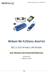
WISNAP WI-FI/SERIAL ADAPTER
802.11 B/G Wireless LAN Module
User Manual and Command Reference
Version 2.36, 2.45
November 12th, 2012
1
2
Overview ......................................................................................................................................... 3
Hardware Interface ........................................................................................................................... 4
2.1
Power ......................................................................................................................................... 4
2.2
Reset.......................................................................................................................................... 5
2.3
UART .......................................................................................................................................... 5
2.4
Status Indicators ......................................................................................................................... 5
2.5
WiSnap M1 External Antenna ......................................................................................................... 6
2.6
Additional WiSnap AAA Dongle Notes.............................................................................................. 6
3 Configuration ................................................................................................................................... 9
3.1
Entering Command Mode .............................................................................................................. 9
3.2
Common Configurations .............................................................................................................. 11
4 WiSnap Command Reference ........................................................................................................... 13
4.1
Command Syntax ...................................................................................................................... 13
4.2
Command Organization .............................................................................................................. 13
5 SET Commands .............................................................................................................................. 14
5.1
AD-HOC Parameters ................................................................................................................... 14
5.2
BROADCAST Parameters ............................................................................................................. 14
5.3
COMM Parameters...................................................................................................................... 15
Page
1 of 83
WiSnap User Manual 2.36, 2.45 11122012-RW
5.4
DNS Parameters ........................................................................................................................ 16
5.5
FTP Parameters ......................................................................................................................... 16
5.6
IP Parameters............................................................................................................................ 16
5.7
OPTIONAL Parameters ................................................................................................................ 18
5.8
SYSTEM Parameters ................................................................................................................... 19
5.9
TIME Server Parameters ............................................................................................................. 22
5.10
UART Parameters .................................................................................................................. 22
5.11
WLAN Parameters .................................................................................................................. 24
6 GET Commands .............................................................................................................................. 28
7 STATUS Commands ........................................................................................................................ 29
8 ACTION Commands ........................................................................................................................ 30
9 FILE IO Commands ......................................................................................................................... 32
10 Advanced Features and Settings ....................................................................................................... 33
10.1
System Timers and Auto Connect Timers .................................................................................. 34
10.2
Wake on Sensor Input ........................................................................................................... 36
10.3
Wake on UART ...................................................................................................................... 37
10.4
UART Receiver, RTS/CTS Hardware Flow Control ....................................................................... 37
10.5
Setting GPIO direction, Alternate Functions and Disabling LEDs ................................................... 38
10.6
Setting Debug Print levels....................................................................................................... 41
10.7
Scan Output Format ............................................................................................................... 41
Firmware Version 2.36 & 2.45 ................................................................................. 41
Firmware Version 2.22 through 2.30 ........................................................................ 43
10.8
UART Heartbeat Messages ...................................................................................................... 43
10.9
Using the Real Time Clock Function .......................................................................................... 44
11 Sending data using UDP .................................................................................................................. 45
11.1
Overview .............................................................................................................................. 45
11.2
UDP Auto Pairing ................................................................................................................... 46
11.3
UDP Retry............................................................................................................................. 46
11.4
Using the UDP Broadcast function ............................................................................................ 46
12 Joining Networks and Making Connections ......................................................................................... 47
12.1
Associate with a network access point ...................................................................................... 48
12.2
Making Connections ............................................................................................................... 49
12.3
Setting up Automatic Connections ........................................................................................... 49
12.4
Controlling Connections using PIO5 and PIO6 ............................................................................ 49
12.5
Using DNS settings ................................................................................................................ 50
12.6
Utilizing the Backup IP address/connect function ....................................................................... 50
13 Using HTML Client Feature ............................................................................................................... 50
13.1
Built-in HTML Client Modes ..................................................................................................... 51
13.2
Automatically periodically connect to web server ....................................................................... 51
13.3
Automatically connect to web server on UART data .................................................................... 52
13.4
Posting binary data: ............................................................................................................... 52
13.5
Auto posting sensor data: ....................................................................................................... 53
13.6
Examples using the HTML client............................................................................................... 53
14 Firmware Upgrade over FTP ............................................................................................................. 55
15 Ad-hoc Networking Mode ................................................................................................................. 57
15.1
Infrastructure and ad-hoc comparison ...................................................................................... 57
15.2
Configuring ad-hoc mode ........................................................................................................ 57
15.3
Scanning for Access Points in Ad Hoc Mode ............................................................................... 58
16 Access Point Networking Mode ......................................................................................................... 59
17 WI-FI Protected Setup (WPS) ........................................................................................................... 62
18 Analog Sensor Capability ................................................................................................................. 64
Automatic sampling of sensor pins: ....................................................................................................... 65
Using the Built-In Sensor Power ............................................................................................................ 66
19 Default Configuration Settings .......................................................................................................... 67
19.1
Restoring Default configuration settings: .................................................................................. 69
20 Boot-up Timing Values .................................................................................................................... 70
21 Supported 3rd Party Access Points ..................................................................................................... 71
22 Command List ................................................................................................................................ 72
23 Release Notes ................................................................................................................................ 76
23.1
Known problems .................................................................................................................... 76
23.2
Current Firmware features and fixes ........................................................................................ 76
Page
2 of 83
WiSnap User Manual 2.36, 2.45 11122012-RW
1
Overview
The “WiSnap” radio module is a complete standalone embedded wireless LAN access device. The
device has an on-board TCP/IP stack and requires only 4 pins (POWER, TX, RX, GND) to design in. The
RS-232 interface can transfer data to remote applications, such as an iPhone app, data logger, or PC
control console. Once initial configuration is set, the radio can automatically access the Wi-Fi network
and send/receive serial data over UART.
Fully Qualified and Wi-Fi Certified 2.4GHz IEEE 802.11b/g transceiver
High throughput, up to 4Mbps sustained data rate with TCP/IP and WPA2
Ultra-low power (4uA sleep, 40mA Rx, 210mA max Tx)
Small, compact surface mount module
On board ceramic chip antenna and U.FL connector for external antenna
8 Mbit flash memory and 128 KB RAM
UART and SPI (future) data/control interfaces
10 general purpose digital I/O
8 analog inputs
Real-time clock for wakeup and time stamping/data logging
Accepts 3.3V regulated or 2-3V battery with on board boost regulators
Supports Ad-hoc and Infrastructure mode connections
On board ECOS-OS, TCP/IP stacks
Wi-Fi Alliance certified for WPA2-PSK
FCC / CE/ ICS certified and RoHS compliant
Features
Host Data Rate Up to 2.7 Mbps for UART
Memory 128 KB RAM, 2MB ROM, 2 KB battery-backed memory, 8 Mbit Flash.
Intelligent, built-in power management with programmable wakeup
Can be powered from regulated 3.3-3.7V source or 2.0-3.0V batteries
Real time clock for time stamping, auto-sleep and auto-wakeup modes
Configuration over UART or wireless interfaces using simple ASCII commands
Over the air firmware upgrade (FTP), and data file upload.
Secure Wi-Fi authentication WEP-128, WPA-PSK (TKIP), WPA2-PSK (AES).
Built in networking applications DHCP client, UDP, DNS client, ARP, ICMP ping, FTP, TELNET,
HTTP
802.11 power save and roaming functions
One of the main applications for this device is the iPhone, since it requires buying additional
authorization hardware to use Bluetooth SPP; the WiSnap in ad-hoc mode is a simple and cost effective
way to connect to iPhone apps. The WiSnap Serial Adapter is more than a cable replacement solution.
By allowing multiple TCP/IP sockets, applications can control and monitor hundreds of Wi-Fi Serial
adapters remotely distributed across a building LAN or campus WAN.
Page
3 of 83
WiSnap User Manual 2.36, 2.45 11122012-RW
2
Hardware Interface
Please see the specific data sheet on the SerialIO.com website for hardware specifications and layout
information, located here:
http://serialio.com/support/wifi/Serialio_WiSnap_GSX_Super_Module_Specs_2.0.pdf
2.1
Power
2.1.1 WiSnap M1 SuRFBoard
There are two options for powering the WiSnap module directly.
DC SUPPLY:
Apply 3.3 VDC power to VBATT (pin 20), and V3.3IN (pin 21).
Tie 3.3VREG-IN (pin 18) to GROUND.
Leave 3.3V-REG-OUT (Pin 17) floating/no connect.
BATTERY:
Apply battery = 2.0 to 3.3VDC to VBATT (pin 20).
Leave V3.3IN pin 21 floating/no connect.
Tie pin 17 to pin 18. (This enables the on board battery boost 3.3V switcher).
There is a built in voltage brownout monitor which will shut down the chip when the voltage drops
below 2.0 VDC.
Warning: Do NOT exceed these voltage ratings or damage to the module will occur!
Notes:
#1: The Sensor inputs SENS0-7 are extremely sensitive to over voltage. Under no conditions
should these pins be driven above 1.2VDC. Placing any voltage above this will permanently
damage the radio module and render it useless.
#2: Placing 5VDC or any voltage above 3.3VDC into the VDD pins of the module will
permanently damage the radio module.
#3: Placing 3.3VDC into the PIO’s while they are set as outputs will permanently damage the
module. The failure mode is a short across GND and VCC.
2.1.2 WiSnap AAA Dongle
The WiSnap AAA Dongle is powered by two AAA batteries, an external AC to 5VDC power cable, or
5VDC (only) on pin 9 of the DB9 connector. Rechargeable NiMH batteries will be trickle charged when
used with an external 5VDC (only) power source.
The power cable is center pin positive, outer cylinder GND. Input MUST be 5 VDC for proper battery
charging. Higher voltages can permanently damage the charger and battery.
NOTE: Although external power is possible, batteries MUST BE CONNECTED in order to
complete the circuit. Without batteries, permanent damage to the unit may result.
WARNING: Do NOT use alkaline batteries while connecting any external power source.
Doing so will cause permanent damage. If you desire to run off AC or external DC power,
this can be accomplished by inserting NiMH re-chargeable batteries.
Page
4 of 83
WiSnap User Manual 2.36, 2.45 11122012-RW
Charging is a trickle charge; it typically takes 10 hours to charge batteries fully from low battery. The
charge rate of the charger is low enough (< 100ma) such that the batteries can be charged indefinitely
with no harm to them.
In configuration mode the show bat command will return the current battery voltage. Note that with
rechargeable NiMh batteries, the voltage will remain relatively unchanged until they go dead.
2.2
Reset
NOTE: The following only applies to the WiSnap M1 module.
Reset is active LOW and is optional/does not need to be connected.
has an internal pull up of 100K to the VBATT.
2.3
The reset pin is 3.3V tolerant and
UART
NOTE: The following only applies to the WiSnap M1 module.
Connect a common ground when using the external TX, RX inputs.
For a 3 wire DB-9 interface, connect TX, RX, and GND only.
Factory default is hardware flow control disabled; CTS and RTS are not required.
PIO’s are not 5.0 VDC tolerant. If using a 5.0 VDC circuit, input, PIO and UART input pins require a
resistor divider. A suggestion is to use a 10K resistor in series with 20k resistor to ground.
2.4
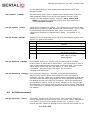
Status Indicators
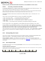
2.4.1 WiSnap M1 SuRFBoard
PIO 4, 5 and 6 are active high and can be connected to external LEDs to provide network, connection
and data status.
State
Red LED (PIO6)
Orange LED (PIO5)
ON solid
Fast blink
Connected over TCP
Not Associated
Rx/Tx data transfer
Slow blink
OFF
Green LED (PIO4)
No IP address or
Config Mode
IP address OK
Associated
Page
5 of 83
WiSnap User Manual 2.36, 2.45 11122012-RW
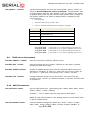
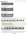
2.4.2 WiSnap AAA Dongle
LEDs found on the WiSnap AAA are slightly different than on the M1.
State
Green LED
Yellow LED
Connected
over TCP
No IP address
Fast blink
or Config
Mode
IP address
Slow blink
OK
Red LED
ON solid
OFF
Blue LED
Full charge
Not Associated
Associated, No
Internet
Associated,
Internet OK
Rx/Tx data
transfer
Low Power
The blue LED blinks when data is sent or received on the serial interface. This does not indicate that
the data was sent over the Wi-Fi connection. If the blue LED is not flashing and your device is sending
data to the serial port, you likely have a connection, incorrect baud rate, or HW flow control (RTS/CTS)
problem.
The blue LED also indicates battery status and will blink slowly when the batteries are low except when
charging. When charging the blue LED remains off. If the device is on while the batteries are charging
the blue LED will come solid when the batteries are fully charged.
There is an additional red LED near the power connector that indicates external power is present at
either the power plug of DB9 connector.
2.5
WiSnap M1 External Antenna
An external antenna with UF.L connection can be mounted onto the WiSnap M1 module. This is most
useful when the device will be embedded inside of another metal casing.
The FCC certified antenna has the following specifications:
Center Freq.
2.45 GHz
Bandwidth
120MHz
Wavelength
½-wave
VSWR
<1.9 typ. At center
Impedance
50 ohms
Gain
2.20dBi
Other antennas can be used, such as a higher gain antenna, but would not be FCC certified.
2.6
Additional WiSnap AAA Dongle Notes
2.6.1 Power Switch and Sleep
The red button on the top of the WiSnap AAA Dongle is a soft ON/OFF switch.
To turn ON the WiSnap AAA Dongle, press down the red button for 1 second, and then release it. You
will see the green, yellow, red and blue LEDs flash in succession. After a moment the blue and yellow
LEDs will go OFF, leaving the red and green LED flashing.
To turn OFF the WiSnap AAA Dongle, press down on the red button for 1 second, and then release it.
The green, yellow, red and blue LEDs flash in succession several times. Then all the LEDs will turn off
and the device will be in sleep mode.
Page
6 of 83
WiSnap User Manual 2.36, 2.45 11122012-RW
By default, the WiSnap AAA Dongle automatically shuts itself off if not connected for more than 3
minutes = 180 seconds. The sleep timer duration is controlled by using the set sys sleep
<seconds> command. Use the get sys to display the current settings of the sleep timer.
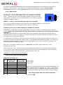
2.6.2 Dipswitches
There are four small configuration switches on the top of the WiSnap
AAA Dongle. You will need a paper clip or flat screwdriver to change
them. Holding the device with the DB9 connector facing to the right,
switches are numbered one to four from bottom to top. The off position
towards the DB9 connector.
on
off
4
3
2
the
is
1
Switch 1 – Ad-hoc override and restoring factory defaults
There are two ways to enable ad-hoc mode from the WiSnap: hardware, and software.
See section 3.1 for more information about ad-hoc networking.
Software ad-hoc is recommended and is enabled by default.
If dipswitch 1 is ON when powering the WiSnap, the device will boot in hardware ad-hoc override
mode. This is only useful if the boot-up configuration is bad and you can’t access the device
otherwise.
The SSID (network name) and other WiFi settings are hardcoded and cannot be changed while in
hardware ad-hoc mode. The SSID of the ad-hoc network will be Wifly-GSX-NN where NN is the last
two digits of the devices MAC address.
To restore factory defaults, power on the device with this switch ON, and then toggle the switch five
(5) times. If there is a config file named "user" on the WiSnap AAA Dongle file system, it is read in as
the factory defaults instead of using the hardcoded defaults. If no "user" config file is present, the
hardcoded factory defaults are used.
The "user" config file is created using the "save user" command, which saves the current
configuration settings.
Even if there is a “user” config file arming and toggling this switch nine (9) times will override the
“user” settings and restore the WiSnap module to the factory hardcoded defaults. This is a bypass
mechanism in case a bad configuration is saved into the “user” file.
Switches 2, 3, and 4 are currently not used.
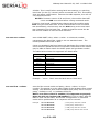
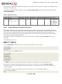
2.6.3 Serial Connector Specification
DB9 connector Pin Out
Pin
WiSnap AAA
Male DB9
WiSnap AAA
Female DB9
1
2
3
4
5
6
7
8
9
NC
RXD
TXD
DTR (=PIO7)
GND
DSR (=PIO8)
RTS
CTS
5V DC Only
NC
TXD
RXD
DON’T USE
GND
5V DC (input)
CTS
RTS
5V DC Only
NOTE: The RS232 interface uses the SIPEX SP3232ECA chip
with capacitor switch to generate the + and – signals and
thus is not driving the full RS232 voltages. Devices stealing
power from the RS232 pins may not have enough voltage.
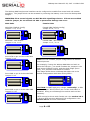
2.6.4 Null-modem and Flow Control Jumpers
Page
7 of 83
WiSnap User Manual 2.36, 2.45 11122012-RW
The WiSnap AAA Dongle serial interface can be configured to enable flow control and null modem
signalling. The jumper block can be accessed by removing the battery cover from the WiSnap AAA
Dongle.
WARNING: Flow control signals are NOT RS-232 signalling tolerant. If these are enabled
with the jumper, do not exceed 3.3 VDC or permanent damage can occur.
Male Units
Female Units
Male DB9 (Default Config)
Jumper 1<>2, 3<>4
Female DB9 (Default Config)
Jumper 2<>4, 1<>3
9
7
5
3
1
10
8
6
4
2
9
7
5
3
1
10
8
6
4
2
Male DB9 - Null Modem
Jumper 2<>4, 1<>3
Female DB9 - Null Modem
Jumper 1<>2, 3<>4
9
7
5
3
1
10
8
6
4
2
Drive DTR on pin 4 of the male DB9
Jumper 7<>8
9
7
5
3
1
10
8
6
4
2
Drive DSR on pin 6 of the male DB9
Jumper 5<>6
10
8
6
4
2
9
7
5
3
1
Note: You can combine jumper configurations to achieve
desired pinouts.
For example, if using the WiSnap AAA Male and wish to
drive the DTR pin*, you would combine the jumpers in the
first image (Default Config), and the third image (Drive
DTR), so 3 jumpers total would be needed.
The image below shows a WiSnap AAA Male unit in the
default configuration while also driving DTR**.
9
7
5
3
1
Drive DCD on pin 1 of the male DB9
Jumper 9<>10
10
8
6
4
2
10
8
6
4
2
9
7
5
3
1
CAUTION: Do NOT apply any voltage *externally* to PIN
4 when Jumper "Drive DTR on pin 4 of the male DB9" is
installed. Doing so will damage the module and void the
warranty.
*DTR cannot be driven with female unit. See section 2.6.3.
**Driving DTR requires additional I/O configuration. See
section 10.5.1 for more information.
Page
8 of 83
WiSnap User Manual 2.36, 2.45 11122012-RW
3 Configuration
3.1
Entering Command Mode
Upon power up, the device will be in data mode. To enter command mode, send the three characters
$$$ and the device will respond with CMD.
While in command mode, the device will accept ASCII bytes as commands.
To exit command mode, send exit<cr>. The device will respond with “EXIT”.
Parameters, such as the SSID, channel, IP address, Serial Port settings, and all other settings can be
viewed and configured in command mode.
ASCII characters can be sent through a terminal emulator connected to the UART or via Telnet. When
using the UART communications settings should match the settings used when RN-131g connects, for
example: the default is 9600 baud rate, 8 bits, No Parity, 1 stop bit, and hardware flow control
disabled.
Use TeraTerm, PuTTY, or SerialIO’s JavaTerm as your terminal emulator. Please DO NOT use
HyperTerminal as it is known to have issues with our products.
Type $$$ on in the terminal emulator. You should see “CMD” returned to you. This will verify that
your cable and comm. settings are correct. Most valid commands will return an “AOK” response, and
invalid ones will return an “ERR” description.
NOTE: You can enter command mode locally over the UART interface at any time when not connected,
and also when connected if the appropriate settings are enabled.
NOTE: When the WiSnap module is powered up, it tries to auto associate to the Access Point stored in
the config settings. If for some reason the module cannot find the Access Point, it goes into auto
association mode and gets busy scanning and trying to join a network. This may cause the UART to
become unresponsive for a brief amount of time and you may lose the data sent to the module while
the module is in this “not associated” state making it difficult to get into command mode and configure
the module
Version 2.21 of the firmware fixes this issue. The auto-join feature is disabled when in command
mode. This makes it easy to configure the module. Auto-join will re-enable when you exit out of
command mode.
IMPORTANT NOTE: Do NOT upgrade the firmware with a WiSnap AAA dongle. Only the
WiSnap M1 module is supported by this firmware.
The auto join feature can be disabled by setting the set wlan join 0. This will prevent the WiSnap
module to attempt to associate to a network that does not exist.
Another alternative is to boot the module in ad-hoc mode by using the PIO9 ad-hoc/factory reset
jumper. If this is high on power up, the module will not associate to any network; it will use the
temporary ad-hoc mode. When in ad-hoc mode, you can configure the network settings.
Page
9 of 83
WiSnap User Manual 2.36, 2.45 11122012-RW
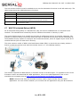
Remote configuration using AD-HOC mode
Using ad-hoc mode to configure the device eliminates the need for the module to be associated with a
network access point. In ad-hoc mode the module creates it own “on demand” network that you can
connect to via your computer like you would to any other network.
To enable ad-hoc mode via hardware, set PIO9 high (3.3V) at power up. On the WiSnap M1, PIO9 is
on the J1 jumper block, and dipswitch 1 on the WiSnap AAA. When the module powers up with PIO9
set high, the WiSnap module creates an ad-hoc network with the following
SSID:
Channel:
DHCP:
IP address:
Netmask:
Wifly-GSX-XX - where XX is the final two bytes of the device’s MAC address
1
OFF
169.254.1.1
255.255.0.0
With the ad-hoc jumper (block 1) in place or dipswitch 1 in the ON position, the above settings
override the saved software configuration settings.
From your computer or smartphone, connect to the Wifly-GSX-XX network.
that does not require a pass phrase or pass key.
This is an open network
NOTE: currently the WiSnap only supports OPEN mode for creating ad-hoc and access point networks.
NOTE: It may take 2-3 minutes for Auto IP in your device to assign an IP address and connect to the
network. You can check IP address of your Windows computer by running the ipconfig command in a
command window. If connected, this command will show you the IP address and netmask for your
computer.
Your IP address must be on the 169.254.x.y subnet otherwise the WiSnap module will not be
accessible.
NOTE: If your machine has both a wireless and wired network interface, you may need to disable the
wired LAN interface hardware before connecting to the ad-hoc network. If the wired LAN is enabled,
the computer may assign an IP address that is not on the same subnet as the WiSnap module.
Once connected and you have a valid IP address, telnet into the WiSnap module on port 2000 with this
command in Windows:
telnet 169.254.1.1 2000
You should see the response “*HELLO*”
You can now enter command mode and configure the module. After configuration is complete,
remember to save your changes with the “save” command. See section 4, WiSnap Command
Reference for more information.
IMPORTANT NOTE: After ad-hoc configuration, make sure to power off the WiSnap and remove the
ad-hoc jumper/turn off switch 1 before powering on the unit, or your configuration will not be active.
In firmware versions 2.28 and higher, you can disable remote configuration, e.g. for security. To
disable remote configuration, use bit 4 in the TCP mode register by issuing the command:
set ip tcp-mode 0x10
Page
10 of 83
WiSnap User Manual 2.36, 2.45 11122012-RW
3.2
Common Configurations
Two common modes of operation for the WiSnap module are A) initiating a connection to a server and
B) listening for a remote host connection. This section will go through the configuration for each setup.
The setups are shown using infrastructure network. i.e. with an access point, however the same can be
done with ad-hoc networking.
Initiating a connection from the WiSnap
Step 1: Set up the WLAN properties so the device will connect to the network automatically upon
power up. In this example we want to connect to the wireless network my_network.
set wlan join 1
// Auto join upon power up
set wlan chan 0
// Scan all channels
set wlan ssid my_network
// Network name
set wlan phrase my_secret_code
// Pass phrase
The join 1 setting ensures that when the module wakes up, it tries to join the access point that
matches the stored SSID, passkey and channel. Channel =0 (the default) will force auto-scanning.
Setting the channel will reduce the time it takes the WiSnap to find and associate.
Step 2: Set up the IP address and port number of the remote server, so the WiSnap can connect when
it wakes up.
set ip host 10.20.20.75
set ip remote 3000
set sys autoconn 2
save
// Set the host IP address
// Set the remote port
// Try to connect to the host every 2 seconds
// Save configuration
NOTE: If autoconn = 1, the WiSnap will only make one attempt to auto connect.
Step 3: Set the wake up and sleep conditions. By default the adapter will wake whenever there is
data written to the serial interface. You can also configure the device to wake up on CTS, on a PIO or
timer. See the command reference for details. We are going to set this up to wake on a timer then
sleep after 2 minutes if there is no connection or if connected and no data has been transferred for 30
seconds.
set sys sleep 120
set sys trigger 2
set conn idle 30
save
reboot
//
//
//
//
//
sleep after 2 minutes if no connection
wake on CTS
disconnect after 30 seconds of no data
save all the settings to the config file
use the new settings
This setup can be tested using TCP server application that opens a socket on port 3000. Port Peeker is
a free application that you can download off the web.
It is available at http://www.linklogger.com/portpeeker.htm
Waiting for the remote host to connect to the serial adapter (listen mode)
In this example we are using a static IP so that the remote host knows where the WiSnap Serial
adapter is on the network. Alternatively you can write your application software to listen for the
broadcast UDP packet (automatically sent by WiSnap by default) to identify the WiSnap Serial adapter
and get the IP address and TCP port number that the WiSnap is listening on.
Page
11 of 83
WiSnap User Manual 2.36, 2.45 11122012-RW
Step 1: Set up the wlan properties so the device will connect to the network automatically upon power
up. In this example we want to connect to the wireless network my_network.
set wlan join 1
// Auto join upon power up
set wlan chan 1
// only look on channel 1
set wlan ssid my_network
// Network name
set wlan phrase my_secret_code
// Pass phrase
Step 2: Configure the WiSnap static IP address so the remote application can connect, turn off DHCP
and set the IP address and netmask.
set ip address 10.20.20.63
// Set the IP address
set ip localport 5030
// Set the local port to listen on
set ip netmask 255.255.255.0
// Set the IP netmask
set ip gateway
// Sets the network gateway
10.20.20.1
set ip dhcp 0
// Turn off DHCP
Step 3: Set the wake up and sleep conditions. In this mode the sleep and wake timers are used to
conserve battery. Since we don’t know when the remote host will connect, the module should to
occasionally wake up and listen for the remote host. The trade off with these timers is that the longer
you sleep, the better your battery life will be but the longer it will take the remote host to connect.
WARNING: Do not set the sleep timer below 5 seconds or it will be impossible to get into command
mode to reprogram this mode without it going back to sleep!
set sys wake 20
set sys sleep 10
save
reboot
//
//
//
//
Wake after 20 seconds
Go to sleep after 10 seconds
Save configuration
restart using the new configuration
At this point you could test this configuration using telnet on a computer sharing the same network to
connect to the WiSnap module.
Enabling Access Point Mode (Requires firmware to 2.42 and higher)
Devices using firmware versions 2.42 and higher are able to put the device into Access Point mode.
Access point mode allows for an alternative for connecting android devices. The device can be put into
access point mode by issuing the following commands:
set wlan ssid WiSnap
// Set the Access Point SSID
set wlan join 7
set ip dhcp 4
// Create an access point on power up
//Turn on the DHCP server
set wlan chan 1
set ip address 1.2.3.4
set ip net 255.255.255.0
set ip gateway 1.2.3.4
save
reboot
// Only broadcast on channel 1
// Set the IP address for the WiSnap device.
//Set the subnet mask
//Set the Access Point gateway
// Save configuration
// restart using the new configuration
When the device reboots, it should be in access point mode.
Page
12 of 83
WiSnap User Manual 2.36, 2.45 11122012-RW
4 WiSnap Command Reference
4.1
Command Syntax
Commands begin with a keyword, and have optional additional parameters, generally space delimited.
Commands and options are case sensitive. Hex input data can be upper or lower case. String text
data, such as SSID is also case sensitive.
The first command is fully decoded and must be complete. Other command parameters can be shorted
by using only the first character.
For example,
set uart baud 115200 is valid,
set uart b 115200
set u b 115200
s uart baud 115200
is also valid,
is also valid, however,
is NOT valid.
Numbers can be entered as either decimal, (like 115200 above) or hex. To enter hex, use “0x” before
the value: 0x<value>. For example, the hex value FF would be entered as 0xFF.
4.2
Command Organization
Commands fall into 5 general categories:
SET COMMANDS – Changes settings immediately and permanently (save command issued).
GET COMMANDS - Retrieve the permanently stored information for display to user.
STATUS COMMANDS - See what is going on with the interface, IP status, etc.
ACTION COMMANDS - Perform action such as scan, connect, disconnect, etc.
FILE IO COMMANDS - Upgrade, load and save configuration, delete files, etc.
NOTE: You must save any changes made or the module will load the previous settings upon reboot or
power up.
When the system boots, all configuration data is loaded into RAM variables from the file called “config”.
The set commands actually only modify the RAM copy of variables in the system. In general, the IP,
WLAN and UART settings need a save and reboot to take effect, since they operate at boot up time.
For example: At power up, you will only associate, set the channel and get your IP address once.
Most of the other commands take effect immediately like the COMM settings and timers. This allows
temporary change of parameters “on the fly” to test features, minimizes power usage and saves on
flash re-write cycles.
Once all configuration is complete, the user must save the settings using the save command to store
the configuration data, otherwise it will not take effect upon reboot or reset. Multiple configurations
can be stored by using the save <filename> command, and these configurations can be loaded
using the load <filename> command.
Page
13 of 83
WiSnap User Manual 2.36, 2.45 11122012-RW
5 SET Commands
These commands begin with “set”. There are 6 major categories.
AD-HOC
BROADCAST
COMM
DNS
FTP
IP
OPTION
SYS
TIME
UART
WLAN
5.1
-
controls the ad-hoc parameters
controls the broadcast hello/heartbeat UDP message
communication and data transfer, timers, matching characters
DNS host and domain
FTP host address and login information
IP settings
optional and not frequently used parameters
system settings such as sleep and wake timers
timer server settings
serial port settings such as baud rate and parity
wireless interface settings, such as SSID, channel, and security options
AD-HOC Parameters
set ad-hoc beacon <ms>
sets the ad-hoc beacon interval in milliseconds where <ms> is a
decimal number from 0 to 65,436. Default is 100.
set ad-hoc probe <num>
sets the ad-hoc probe retry count. Default is 5. This is the number of
consecutive probe responses that can be lost before declaring “ADHOC is lost” and disabling the network interface.
5.2
BROADCAST Parameters
set broadcast address <addr> sets the address to which the UDP hello/heartbeat message is sent.
The default address is 255.255.255.255
set broadcast interval <value> sets the interval at which the hello/heartbeat UDP message is
sent. Interval is specified in seconds. The value is a mask that is
ANDed (compared) to a free running seconds counter. For example:
If the interval is 0x1, the module sends one packet every 2 seconds.
If the interval is 0x2. The module sends two packets every 4 seconds.
If the interval is 0x3, the module sends one packet every 4 seconds.
If the interval is 0x6, the module sends two packets every 8 seconds.
If the interval is 0x7, the module sends one packet every 8 seconds.
The minimum interval value is 1 (every 2 seconds) and max value is
0xff (every 256 seconds). Setting the interval value to zero disables
sending UDP broadcast messages. The default interval is 7.
set broadcast port <port>
sets the port number to which the UDP hello/heartbeat message is
sent. The default port is 55555.
Page
14 of 83
WiSnap User Manual 2.36, 2.45 11122012-RW
5.3
COMM Parameters
set comm $ <char>
sets character used to enter command mode. Typically used when
“$$$” is a possible data string. Default is ‘$’. Care should be taken
when setting this to note the new character as once this setting is
saved every subsequent reboot will ignore “$$$” and look for
“<char><char><char>”.
set comm close <string>
sets the ASCI string that is sent to the local UART when the TCP port is
closed. If no string is desired, use 0 as the <string> parameter. Max
string length is 32 characters. Default is *CLOS*
set comm open <string>
sets the string that is sent to the local UART when the TCP port is
opened. If no string is desired, use 0 as the <string> parameter. Max
string length is 32 characters. Default is *OPEN*
set comm remote <string>
sets the string that is sent to the remote TCP client when the TCP port
is opened. If no string is desired, use 0 as the <string> parameter.
Max string length is 32 characters. Default is *HELLO*
set comm idle <secs>
sets the Idle Timer Value. This is the number of seconds with no
transmit or receive data before the connection is closed automatically.
Default is 0, never disconnect on idle.
set comm match <value> | <hex> sets the match character, where <value> is a decimal number
from 0 to 127 or a hex number from 0 to 7F. When this configuration
option is set, the module sends an IP packet each time the match
character appears in the data. You enter <value> either as the decimal
(e.g., 13) or hex (e.g., 0xd) equivalent of the of the ASCII character.
Setting the match character to 0 disables matching.
Flush timer is one of three ways to control TCP/IP packet forwarding.
The others are match character and size. For more information see
section 10.4
set comm size <value>
sets the flush size. An IP packet will be sent each time “value” bytes
are received. Default is 64 bytes. You should set this value to the
largest possible setting to maximize TCP/IP performance. Maximum
value = 1420 (at 9600) bytes.
NOTE: This value is set automatically when the baud rate is set, in an
attempt to optimize the link. It is assumed that higher baud rates
equates to more data and hence the flush size is increased.
Flush size is one of three ways to control TCP/IP packet forwarding.
The others are match character and timer. For more information see
section 10.4
set comm time <num>
sets the flush timer. An IP packet will be sent if no additional bytes are
received for “num” milliseconds. Num is one milliseconds intervals. 1 is
the minimum value. Default is 10 (10 milliseconds). Setting this value
to 0 will disable forwarding based on the flush timer.
Page
15 of 83
WiSnap User Manual 2.36, 2.45 11122012-RW
Flush timer is one of three ways to control TCP/IP packet forwarding.
The others are match character and size. For more information see
section 10.4
5.4
DNS Parameters
set dns address <addr>
sets the IP address of the DNS sever, where <address> is an IP
address in the form <value>.<value>.<value>.<value> with <value>
being a number between 0 and 255. This address is automatically set
when using DHCP; you must set the DNS IP address for static IP or
automatic IP modes.
set dns name <string>
sets the name of the host for TCP/IP connections to <string>, where
<string> is up to 32 characters (32 bytes).
set dns backup <string>
sets the name of the backup host for TCP/IP connections to <string>,
where <string> is up to 32 characters (32 bytes). The FTP client uses
the backup string to download the firmware via the ftp update
command. Default: rn.microchip.com
5.5
FTP Parameters
set ftp dir <string>
sets the starting directory on the FTP server, where <string> is up to
32 characters. To read/write to subfolders, use the \ character. To
indicate the root directory, use a period.
set ftp filename <file>
sets the name of the file transferred when issuing the “ftp u” or “ftp g”
commands, where <filename> is the firmware image. If you specify
any file other than the firmware image, the WiSnap module downloads
the file and issues the UPDATE FAIL=3 error.
set ftp addr <addr>
sets the ftp server IP address. Default 0.0.0.0.
set ftp remote <port>
sets the ftp server remote port number (default is 21).
set ftp user <name>
sets the ftp user name for accessing the FTP server.
set ftp pass <pass>
sets the ftp password for accessing the FTP server.
set ftp time <value>
sets the FTP timeout value, where <value> is a decimal number that is
five times the number of seconds required. The module uses this timer
to close the FTP connection automatically after the specified time.
5.6
IP Parameters
set ip address <addr>
sets the IP address of the WiSnap module, where <address> is an IP
address in the form <value>.<value>.<value>.<value> with <value>
being a number between 0 and 255. If DHCP is turned on, the IP
address is assigned and overwritten during association with the access
point.
Page
16 of 83
WiSnap User Manual 2.36, 2.45 11122012-RW
Example: “set ip a 10.20.20.1”
set ip backup <addr>
sets a secondary host IP address. If the primary host IP is not
reachable the module will try the secondary IP address if set.
set ip dchp <value>
enable/disable DHCP mode. If enabled, the IP address, gateway,
netmask, and DNS server are requested and set upon association with
access point. Any current IP values are overwritten.
DHCP Cache mode can reduce the time it takes the module to wake
from deep sleep thus saving power. In cache mode, the lease time is
checked and if not expired the module uses the previous IP settings. If
the lease has expired the module will attempt to associated and use
DHCP to get the IP settings. DHCP cached IP address does not survive
a power cycle or reset.
Mode
0
1
2
3
4
set ip flags <value>
Protocol
DHCP OFF, use stored static IP address
DHCP ON, get IP address and gateway from AP
Auto-IP, generally used with Ad-hoc networks
DHCP cache mode, Uses previous IP address if
lease is not expired (lease survives reboot)
Enables DHCP server in soft AP mode.
Set TCP/IP advanced functions. Value is a bit mapped flag register.
Default = 0x7.
Bit
0
1
2
3
4
5
6
7
Function
TCP connection status. See note below
Bypass Nagle algorithm and use TCP_NODELAY
TCP retry enabled (42 total)
UDP retry (attempts retry if no ACK from UDP)
DNS host address caching enabled
ARP table caching enabled
UDP auto pairing enabled
Add 8 byte timestamp to UDP or TCP packets
NOTE: When the link to an associated to an access point is lost while
a TCP connection is active, the TCP connection can be left in hung/
inconsistent state. In some cases, the TCP connection will not recover.
In version 2.20 and later, if the link to the access point is regained
within 60 seconds, the TCP connection will survive.
With version 2.20 we have changed the operation of bit0 in the “ip
flags” register. Previously this bit specified the TCP copy function, but
controls the TCP socket function while associated on a network.
If bit 0 is set (default) TCP connections are kept open when the
connection to the access point is lost.
If bit 0 is cleared (by setting “set ip flags 0x6” for example)
then when the connection to the access point is lost and TCP is
connected, the connection will be closed.
Page
17 of 83
WiSnap User Manual 2.36, 2.45 11122012-RW
set ip gateway <addr>
sets the gateway IP address, If DHCP is turned on, the gateway IP
address is assign and overwritten during association with the access
point.
set ip host <addr>
sets the remote host IP address. This command is used for making
connections from the WiSnap module to a TCP/IP server at the IP
address <addr>.
set ip localport <num>
sets the local port number to listen for incoming connections, where
<num> is an integer number representing the port.
set ip netmask <value>
sets the network mask. If DHCP is turned on, the net mask is assign
and overwritten during association with the access point.
set ip protocol <value>
sets the IP protocol. Value is a bit mapped setting. To connect to the
WiSnap module over TCP/IP such as Telnet the device must have the
use the TCP Server protocol / bit 2 set. To accept both TCP and UDP
use value = 3 (bit 1 and bit 2 set)
Bit Position
0
1
2
3
4
Protocol
UDP
TCP Server & Client (Default)
Secure (only receive packets with IP address
matches the
store host IP)
TCP Client only
HTTP client mode
set ip remote <value>
sets the remote host port number for outgoing connections.
set ip tcp-mode <mask>
This command controls the TCP connect timers, DNS preferences, and
remote configuration options. <mask> is a hex number referring to a
bit-mapped register as shown below.
Bit Position
0
1
2
3
4
Example:
5.7
Protocol
Shorten the TCP connect timer (use with bit 1).
Shorten the TCP connect timer (use with bit 0).
Forces the module to use DNS first to resolve
the IP address, even if the host IP is set.
Reserved.
Disables remote configuration security purposes.
set ip tcp-mode 0x4
set ip tcp-mode 0x10
// Forces the module to use DNS
// Disables remote configuration
OPTIONAL Parameters
set opt jointmr <msecs>
Join timer is the time in milliseconds (default=1000) the join function
will wait for the an access point to complete the association process.
This timer is also the timeout for the WPA handshaking process.
set opt sensor <mask>
Deprecated in firmware versions 2.23 and later. Use set q sensor.
Bitmask value that determines which sensor pins to sample when
Page
18 of 83
WiSnap User Manual 2.36, 2.45 11122012-RW
sending data using the UDP broadcast packet and the HTTP auto
sample function.
set q sensor
<mask>
specifies which sensor pins to sample when sending data using the
UDP broadcast packet or the HTTP auto sample function, where
<mask> is a bit-mapped register. Example: set q sensor 0xff.
NOTE: In versions of firmware prior to 2.23, this command is
named set option sensor
set opt replace <char>
replacement character for spaces. The replacement character is used
when entering SSID and pass phrases that include space. This is used
by the WiSnap command parser only. Each occurrence of the
replacement character is changed into a space. The default is “$”
(0x24)
set opt format <mask>
settings for HTTP client/web server value is a bitmapped register. See
Section 13, web server modes.
Bit
0
1
2
3
4
set opt deviceid <string>
Function
Automatically send HTML data header based on broadcast
interval.
Send users BINARY data (converted to ASCII hex )
Sample the GPIO and AtoD pins and format to ASCII hex
Appends &id= <the value of the deviceid string set with “set
opt device <string>”>
Appends &rtc= <real time clock value in message as 32 bit
HEX value in format
aabbccddeeff>
Configurable Device ID - can be used for storing serial numbers,
product name or other device information. This information is sent as
part of the broadcast hello packet that is sent as a UDP. The current
value can be shown with the “get option” or “show deviceid”
commands. Max string size is 32 bytes. The default is
“WiSnap<DEVICEID>M1”.
set opt password <string> TCP connection password. Provides minimal authentication by
requiring any remote device that connects to send and match a
challenge <string>. When set, all newly opened connections must first
send the exact characters that match the stored password otherwise
the WiSnap module will close the connection. When the password is
set the WiSnap module sends the string “PASS?” to the remote host.
All characters in the string must be sent in one TCP packet. Max string
size is 32 bytes. To disable the password feature use string=0 which is
the default.
5.8
SYSTEM Parameters
set sys autoconn <secs>
TCP mode: sets the auto connect timer. This command causes the
module periodically connect to the host. The timer <secs> determines
how often to connect to the stored remote host. If set to 1, the
module will only make one attempt to auto connect upon power up. If
Page
19 of 83
WiSnap User Manual 2.36, 2.45 11122012-RW
set to 2 or greater auto connect will re-open the connection after the
connection is closed. Default=0 disables.
set sys autosleep <num>
Sets the auto-sleep timer. 0 disables. If the protocol is set to UDP
ONLY, this timer is used as a quick sleep function. Device will sleep
<num> ms after transmission of the first UDP packet.
set sys iofunc
sets the IO port alternate functions. Bit-mapped value. For more
details see section 10.5
set sys mask
<value>
<mask>
set sys printlvl <value>
sets the IO port direction mask. Bit-mapped value. For more
information see section 10.5
sets the debug print messages printed by the WiSnap module on the
UART, where <value> is one of the values shown on the table below.
Default is 1.
Value
Description
0
Quiet mode. Messages are not printed when the module wakes up or powers up.
1
Print all status messages.
2
4
0x4000
0x10
Print only critical network access point connection level status, e.g., Associated! or
Disconnect from <SSID>.
Print the DHCP and IP address status information. After you have verified the
module’s configuration, you can turn off this option so that the messages do not
interfere with the data.
Change the scan format output to an MCU friendly format.
Enables the UART heartbeat message. See “Error! Reference source not found.”
for more details.
set sys output <value> <mask> sets output PIO pins to HIGH or LOW. Bit-mapped value.
Optional mask only sets a subset of pins.
Example: To toggle GPIO8, use the following commands:
set sys mask 0x21f0
// Set GPIO8 as output
set sys sleep
<secs>
set sys output 0x0100 0x0100
// Drives GPIO8 high
set sys output 0x0000 0x0100
// Drives GPIO8 low
sets the sleep timer, where <value> is a decimal number. The sleep
timer is the time (in seconds) after which the module goes to sleep.
This timer is disabled during an open TCP connection. When the TCP
connection is closed, the module counts down and puts the module to
sleep after <value> seconds. Setting the value to 0 disables the sleep
timer, and the module will not go to sleep based on this counter. 0
disables.
NOTE: If not using Sensor pins to wake the module, be sure to set the
wake timer before issuing the sleep timer or the module will not wake
up.
Page
20 of 83
WiSnap User Manual 2.36, 2.45 11122012-RW
See section 10.1 for more details on using system timers
set sys trigger <value>
sets the sensor input(s) to wake on (0-3). With this parameter setting,
the module wakes from sleep state using the sensor input 0, 1, 2, and
3, where <flag> is a decimal number referring to a bit-mapped
register as shown in the table below and <mask> is a hex number.
You use either <flag> or <mask> with this parameter setting. This
command sets the sensor input(s) to wake on (0 to 3). Setting <flag>
to 0 disables wake on sensor inputs. Bit-mapped value.
Bit Position
Description
0
Trigger sensor input 0.
1
Trigger sensor input 1.
2
Trigger sensor input 2.
3
Trigger sensor input 3.
4
Enable WPS function.
5
Enable sleep on GPIO8.
The following table describes how you can wake the module using
sensor input.
Wake on Sensor Input
Value
Command
0
1
set sys trigger 1
1
2
set sys trigger 2
2
4
set sys trigger 4
3
8
set sys trigger 8
NOTE: Setting the system trigger value to 0x10 enables WPS functionality. WPS is
disabled by default.
Setting the trigger value to 0x20 (i.e., using <mask>) puts the module to sleep when
GPIO8 is pulled high. To enable this feature, use the set sys trigger 0x20 command.
This command makes GPIO8 an interrupt pin and puts the module to sleep as soon as
it is pulled high, regardless of the module’s state; the module goes to sleep even if it is
associating with a network or has an open, active TCP connection.
This command is useful for when the module is failing to associate with network
because it is out of range (or for any other reason), or if the module must be put to
sleep quickly.
NOTE: GPIO8 must be low on power up and stay low until you want to put the
module to sleep.
set sys wake
<secs>
sets the auto wake timer. 0 disables. See section 10.1 for more details
on using system timers
Page
21 of 83
WiSnap User Manual 2.36, 2.45 11122012-RW
set q power
<value>
register automatically turns on the sensor power, where <value> is
shown in Error! Reference source not found.. This parameter sets
an 8-bit register with two 4-bit nibbles. If the top nibble is set, power
is applied upon power up and removed upon power down or sleep. If
the bottom nibble is set, power is applied when a sampling event
occurs such as:
UDP broadcast
Automatic web posting of sensor data
Power is removed immediately after sampling is complete
Value
Sensor pin voltage
0
Turn off the sensor power.
1
Ground the sensor pin.
2
1.2-V internal regulated reference.
3
VBATT input pin.
4
3.3-V output of on board regulator.
Example:
set
set
set
set
5.9
q
q
q
q
power
power
power
power
0x20
0x02
0x40
0x04
//
//
//
//
Sets
Sets
Sets
Sets
power
power
power
power
to
to
to
to
1.2
1.2
3.3
3.3
V
V
V
V
automatically upon power up
when a sampling event occurs
automatically upon power up
when a sampling event occurs
TIME Server Parameters
set time address <addr>
sets the time server address. (sNTP servers)
set time port <num>
sets the time server port number. Defaults to 123 which is almost
always the sNTP server port.
set time enable <value>
Enable or disable fetching time from the specified sNTP time server.
Default=0= disabled. A value or 1 gets time only once on power up.
Any value > 1 gets time continuously every <value> minutes.
set time raw <value>
setting parameter allows you to set the RTC raw value from the
console, where <value> is a decimal number in seconds. The RTC ticks
at 32,768 Hz.
5.10
UART Parameters
set uart baud <rate>
set the UART baud rate. Valid settings are {2400, 4800, 9600, 19200,
38400, 57600, 115200, 230400}.
Example : “set u b 9600” sets the baud rate to 9600 baud.
NOTE: the RS-232 interface on the WiSnap does not work below 2400
or above 230400 baud.
set uart instant <rate>
This immediately changes the baud rate, where <value> is 2400,
4800, 9600, 19200, 38400, 57600, 115200, 230400, 460800, or
Page
22 of 83
WiSnap User Manual 2.36, 2.45 11122012-RW
921600. This is useful when testing baud rate settings, or switching
baud rate “on the fly” remotely while connected over TCP. This setting
does not affect configuration. Returns the AOK response, but will not
exit command mode.
NOTE: In firmware version 2.22 and lower, the module does NOT
return an AOK over telnet before exiting command mode.
If used in local mode, the baud rate changes and the module sends
AOK using the new baud rate. If the host switches to the new baud
rate immediately, the host may see the AOK string at the new baud
rate. Depending on the baud rate, it takes at least ten times the bit
rate for the module to issue the first character.
set uart raw <value>
sets a RAW UART value, where <value> is a decimal number
representing the baud rate. Used to set non-standard rates. The
lowest possible baud rate is 2400.
Using non-standard raw baud rates with hardware flow control can be
more useful at speeds as the microcontroller interfaced to the module
may be able to better match the UART speed and get better results.
The table below shows the supported raw baud rates:
Raw Baud Rate
Comment
458,333
This is 460,800.
500,000
Raw baud rate.
550,000
Raw baud rate.
611,111
Raw baud rate.
687,599
Raw baud rate.
785,714
Raw baud rate.
916,667
This is 921,600.
1,100,000
Raw baud rate.
Example : “set u r 7200” sets the baud rate to 7200 baud.
set uart flow <value>
sets the flow control mode and parity, where <value> is a hex
number. The setting is in the upper nibble of the hardware flow control
setting. The default is flow control disabled with parity set to none/no
parity. Default=0=off, 1= hardware RTS/CTS.
NOTE: once flow control is enabled, it is important to properly
Drive the CTS pin (active LOW enabled) If CTS is HIGH, data will
NOT be sent out the UART, and further configuration in command
mode will be problematic as no response will be received.
Example:
set
set
set
set
uart
uart
uart
uart
Page
flow
flow
flow
flow
0x21
0x20
0x31
0x30
23 of 83
//
//
//
//
Even parity with flow control
Even parity without flow
Odd parity with flow control
Odd parity without flow control
WiSnap User Manual 2.36, 2.45 11122012-RW
set uart mode <mask>
sets the UART mode register, where <mask> is a hex number masking
a bit-mapped value as shown below.
Bit Position
Function
NOECHO - disables echo of RX data while in
0
command mode
1
DATA TRIGGER makes connection on RX data
2
Reserved
3
Enable Sleep on RX BREAK signal
4
UART RX data buffer, See Note (*).
The version string <x.xx> \r\n is replaced with the
5
replace character in the command prompt ($ by
default)
NOTE (*): With firmware version 2.27 and higher, bit 4’s
functionality has changed. When a TCP connection is closed, if there
is RX data in the UART receiver, it is flushed by default.
When a TCP connection is closed, currently if there is RX data in the
UART receiver, it is held until:
1) more chars come in, in which case it will get flushed, or
2) no chars come in and a new connection is made, then the
chars will get forwarded.
Example: set uart mode 0x10 //Enable the UART data buffer
set uart tx
<0, 1>
Disables or enables the UART’s TX pin (GPIO10), where <value> is 1
or 0. Disabling the pin (<value> = 0) sets GPIO10 as an input with a
weak pull down.
NOTE: Firmware version 2.36/2.45 and higher supports parity with the
set uart flow command.
5.11
WLAN Parameters
set wlan auth <value>
Sets the authentication mode. Not needed unless using auto join mode
2. i.e. set wlan join 2
NOTE: During association the WiSnap module interrogates the Access
Point and automatically selects the authentication mode.
The current release of WiSnap firmware supports these security
modes:
• WEP-128 (open mode only, NOT shared mode)
• WPA2-PSK (AES only)
• WPA1-PSK (TKIP only)
• WPA-PSK mixed mode (some APs, not all are supported)
Value
0
1
2
3
Authentication Mode
Open (Default)
WEP-128
WPA1
Mixed WPA1 & WPA2-PSK
Page
24 of 83
WiSnap User Manual 2.36, 2.45 11122012-RW
4
5
6
8
WPA2-PSK
Not Used
Ad-hoc, Join any Ad-hoc network
WPE-64
NOTE: Currently, WPA2-Enterprise security networks requiring a
username are not currently supported.
set wlan channel <value> <flag>
sets the wlan channel, where <value> is a decimal number from 1 to
13 representing the valid range for a fixed channel. If 0 is set, then a
scan is performed, using the SSID, for all the channels set in the
channel mask. The <flag> is the optional character i (meaning
immediate). The i flag allows you to create a temporary AP mode setup
without having to reboot or save the settings. See example 2 below:
Example 1:
set wlan channel 2
// Set the WLAN channel to 2
Example 2:
set wlan channel 1 i
set wlan join 7
set ip address 1.2.3.4
set ip gateway 1.2.3.4
set ip netmask 255.255.255.0
set ip dhcp 4
join <SSID>
// Use DHCP server
// Module goes into AP mode
set wlan ext_antenna <0, 1> determines which antenna is active, use 0 for chip antenna, 1 for
UF.L connector. Default = 0. Only one antenna is active at a time and
the module must be power cycled after switching the antenna.
set wlan join <value>
sets the policy for automatically joining/associating with network
access points. This policy is used when the module powers up,
including wake up from the sleep timer.
Value
0
1
2
3
4
7
Policy
Manual, do not try to join automatically
Try to join the access point that matches the
stored SSID, passkey and channel. Channel can
be set to 0 for scanning. (Default)
Join ANY access point with security matching the
stored authentication mode. This ignores the
stored SSID and searches for the access point
with the strongest signal. The channels searched
can be limited by setting the channel mask.
Reserved – Not used
Create an Ad-hoc network, using stored SSID, IP
address and netmask. Channel MUST be set.
DHCP should be 0 (static IP) or set to Auto-IP
with this policy. (unless another Ad-hoc device
can act as DHCP server)
This policy is often used instead of the hardware
jumper to create a custom Ad-hoc network
Create a soft AP network using stored SSID, IP
Address, netmask, channel, etc. This mode
applies only to firmware versions supporting soft
AP mode, not ad hoc mode.
Page
25 of 83
WiSnap User Manual 2.36, 2.45 11122012-RW
set wlan hide <0, 1>
Hides the WEP key and WPA passphrase. When set, displaying the
wlan settings shows ****** for these fields. To unhide the passphrase
or passkey, re-enter the key or passphrase using the set wlan key or
set wlan passphrase command. Default = 0, don’t hide.
set wlan key <value>
sets the 128 bit WEP key. If you are using WPA or WPA2 you should
enter a pass phrase with the set wlan passphase command. Key must
be EXACTLY 13 bytes (26 ASCII chars). Data is expected in HEX
format, leading “0x” should NOT be used here.
Example : “set w k 112233445566778899AABBCCDD”
Hex digits > 9 can be either upper or lower case.
The WiSnap only supports “open” key mode, 128 bit keys for WEP.
WEP-128, shared mode is not supported as it is known to be easily
compromised and has been deprecated from the Wi-Fi standards.
set wlan linkmon <value>
sets the link monitor timeout threshold. If set to 1 or more, WiSnap
will scan once per second for the AP it is associated with. The value is
the threshold of failed scans before the WiSnap declares “AP is Lost”,
de-authenticates. The WiSnap will retry the association based on the
join policy variable. A value of 5 is recommended, as some APs will
not always respond to probes. Default is 0 (disabled). Without enabling
this feature, there is no way to detect if an AP is no longer present
until it becomes available again (if ever).
set wlan mask <value>
sets the wlan channel mask used for scanning channels with the autojoin policy 1 or 2, used when the channel is set to 0. Value is a bitmap where bit 0 = channel 1. Input for this command can be entered
in decimal or hex if prefixed with 0x. Default value is 0x1FFF (all
channels)
set wlan num <value>
sets the default WEP key to use. 1-4 is the valid range.
Example : “set w n 2” sets the default key to 2.
set wlan phrase <string>
sets the passphrase for WPA and WPA2 security modes. 1-64 chars.
The passphrase can be alpha and numeric, and is used along with the
SSID to generate a unique 32 byte Pre-shared key (PSK), which is
then hashed into a 256 bit number. Changing either the SSID or this
value re-calculates and stores the PSK.
If exactly 64 chars are entered, it is assumed that this entry is already
an ASCII HEX representation of the 32 byte PSK and the value is
simply stored.
For passphrases that contain spaces use the replacement character $
instead of spaces. For example “my pass word” would be entered
“my$pass$word”. The replacement character can be changed using
the optional command set opt replace <char>.
Example : “set w p password” sets the phrase to ‘password’.
Page
26 of 83
WiSnap User Manual 2.36, 2.45 11122012-RW
set wlan rate <value>
sets the wireless data rate. Lowering the rate increases the effective
range of the WiSnap module. The value entered is mapped according
to the following table:
Value
0
1
2
3
4-7
8
9
10
11
12
13
14
15
set wlan ssid <string>
Wireless Data Rate
1 Mbit/sec
2 Mbit/sec
5.5 Mbit/sec
11 Mbit/sec
Invalid
6 Mbit/sec
9 Mbit/sec
12 Mbit/sec
18 Mbit/sec
24 Mbit/sec (default)
36 Mbit/sec
48 Mbit/sec
54 Mbit/sec
sets the WLAN SSID to associate with. 1-32 chars.
NOTE: If the passphrase or SSID contain SPACE (‘ ‘)
characters, these can be entered using substitution via the “$”
character.
For example, if the SSID of the AP is “yellow brick road”
You would enter “yellow$brick$road”
Using the ‘get w” command will properly display the value:
SSID=yellow brick road.
set wlan window <value>
sets the IP maximum buffer window size. Default is 1460 bytes.
set wlan tx <value>
sets the Wi-Fi transmit power, where <value> is a decimal number
from 1 to 12 that corresponds to 1 to 12 dBm. The default, 0,
corresponds to 12 dB, which is the maximum TX power. Setting the
value to 0 or 12 sets the TX power to 12dBm.
NOTE: This command applies only to the RN-171 module; it is not
applicable to the RN-131. The transmit power on the RN-131 is
fixed to 18 dBm. If you send this parameter to the RN-131, it issues
an error message ERR: Bad Args.
Page
27 of 83
WiSnap User Manual 2.36, 2.45 11122012-RW
6 GET Commands
These commands begin with “get”. They display the current values.
get ad-hoc
display all ad-hoc settings.
get broadcast
will display the broadcast UPD address, port and interval
get com
display comm. settings.
get dns
display DNS settings.
get everything
displays all configuration settings, useful for debug.
get ftp
display FTP settings.
get ip <a>
display IP address and port number settings. If the “a” parameter is added on,
only the current IP address value will be shown.
get mac
display the device MAC address.
get optional
display the optional settings like device ID.
get q
display the sensor settings (sensor mask and sensor power settings).
get sys
display system settings, sleep, wake timers, etc.
get time
display the time server UDP address and port number.
get wlan
display the SSID, channel, and other WLAN settings.
get UART
display the UART settings.
ver
return the software release version.
Page
28 of 83
WiSnap User Manual 2.36, 2.45 11122012-RW
7 STATUS Commands
These commands begin with show, and they return the current values of variables in the system. In
some cases, for example IP addresses, the current values are received from the network, and may not
match the stored values. Except where noted, the show commands do not have any parameters.
show bat
Displays current battery voltage, (only valid for SerialIO.com battery powered
products like the WiSnapAAA)
show connection
Displays connection status in this HEX format: 8XYZ
Bit
location
Function
Value
13-16
9-12
7
6
5
4
fixed
8
channel
1-13
DNS found
1=resolved
DNS server
1=
contacted
Authen
1= OK
Assoc
1=OK
0-3
TCP status
0= Idle,
1=Connected
3= NOIP
4= Connecting
show io
Displays IO pin levels status in this HEX format: 8<ABC>. For example: show i
returns 8103 indicates pins 0, 1 and 9 high level.
show net
Displays the current network status, association, authentication, etc., where <char>
is the optional parameter n. Using the n parameter displays only the MAC address of
the access point with which the module is currently associated.
show rssi
Displays current last received signal strength.
show stats
Displays current statistics, packet rx/tx counters, etc.
show time
Displays number of seconds since last powerup or reboot.
show q <0-7> Display the the value of the analog interface pin, where <value> is 0 to 7. The A/D
reading is 14 bits with a range of 0 to 400 mV (therefore, the resolution is 24 uV).
The output is in uV (1,000 millivolts). The module returns a value in the format
8xxxxx, where xxxxx is the voltage in microvolts sampled on the channel you
requested.
NOTE: If a web post or UDP broadcast samples the data, the data is shifted as
described in the “UDP Broadcast” section.
show q 0x1<mask> Displays multiple analog interface values at once. The channels displayed is
controlled by a bit mask which is proceeded by a 0x1xx where xx mask is the bit
mask of the channels. For example, to read channels 0, 1, and 7, send:
show q 0x183
Which returns 8<chan0>, 8<chan1>, 8<chan7>, \r\n
Page
29 of 83
WiSnap User Manual 2.36, 2.45 11122012-RW
8
ACTION Commands
The action commands allow you to enter and exit command mode, join networks, etc. Except where noted, these commands
do not have any parameters.
$$$
enter command mode Characters are PASSED until this exact
sequence is seen. If any bytes are seen before these chars, or after
these chars, in a 250ms window, command mode will not be entered
and these bytes will be passed on to other side.
close
disconnect a TCP connection.
exit
exit command mode. Exit command mode. “EXIT” will be displayed.
factory RESET
Loads factory defaults into the RAM configuration. Note that the
RESET must be capitalized. This command also writes the settings
out to the standard config file. After this command the module then
needs to be rebooted for settings to take effect.
join <ssid>
joins the network <ssid>. If network is security enabled you must set
the pass phrase with the set wlan phrase command prior to issuing
the join command.
NOTE: The <ssid> must not contain spaces. If the SSID contains
spaces, use a $ instead of the space, e.g., MY$NETWORK to
represent MY NETWORK.
join # <num>
join a network from the scan list. <num> is the entry number in the
scan list that is returned from the scan command. If network is
security enabled you must set the pass phrase with the set wlan
phrase command prior to issuing the join command.
Example: join # 1
leave
disconnects from currently associated Access Point.
lites
Causes the LEDs lights to start blinking. Issuing the command a
second time stops the blinking.
lookup <string>
Causes the module to perform a DNS query, where <string> is the
host name for which to search.
Example: lookup serialio
open <addr> <port>
//Searches for the host serialio
opens a TCP connection to the given IP port and address. If no
arguments are provided, the device will attempt to connect to the
stored remote host IP address and remote port number. <addr> can
also be a DNS hostname and will be resolved if entered.
ping <g | h | i | addr> <num> ping remote host. Default sends 1 packet. Optional <num> sends
<num> pings at 10 per second.
Page
30 of 83
WiSnap User Manual 2.36, 2.45 11122012-RW
ping 10.20.20.12 10 – pings IP address 10 times
ping g
pings the gateway, the gateway IP address is loaded if DHCP is turned
on, otherwise it should be set with the set ip gateway <addr>
command
ping h
pings the stored host IP address, the host IP address can be set with
the set ip host <addr> command
ping i
pings a known Internet server at www.neelum.com by first resolving
the URL (proves that DNS is working and proves the device has
internet connectivity).
ping 0
terminates a ping command
reboot
forces a reboot of the device (similar to power cycle)
scan <time> <P>
Performs an active probe scan of access points on all 13 channels.
Returns MAC address, signal strength, SSID name, security mode.
Default scan time is 200ms / channel = about 3 seconds.
time is an optional parameter, this is the time in ms per channel.
For example, “scan 30” reduces the total scan time down to about 1
second. This command also works in ad-hoc mode. If the optional P
parameter is entered, the module will perform a passive scan, and list
all APs that are seen in passive mode.
sleep
Puts the module to sleep mode. The module can come out of sleep
mode by either sending characters over the UART or by using the wake
timer.
time
Sets the Real time clock by synchronizing with the time server
specified with the time server parameters (see section 0) This
command sends a UDP time server request packet.
Page
31 of 83
WiSnap User Manual 2.36, 2.45 11122012-RW
9
FILE IO Commands
del <name> <num>
Deletes a file. Optional <num> will override the name and use the
sector number shown in the “ls” command.
load <name>
Reads in a new config file.
ls
Displays the files in the system
save
Saves the configuration to “config” (the default file).
save <name>
Saves the configuration data to a new file name
boot image <num>
Makes file <num> the new boot image.
ftp get <name>
Retrieves a file from the remote FTP server.
the stored ftp filename is used.
ftp update <name>
Deletes the backup image, retrieves new image and updates the boot
image.
Page
32 of 83
If <name> not specified,
WiSnap User Manual 2.36, 2.45 11122012-RW
10
Advanced Features and Settings
This chapter describes the advanced features of the WiSnap module. It describes the techniques to put
the module in sleep, wake up from sleep and methods to open a TCP connection when awake. We also
discuss the UART flow control, alternative GPIO functions and Real Time Clock.
The table below describes the possible methods of putting the module to sleep.
Method
Interface
Description
“sleep”
command
UART
Get into command mode using $$$ and issue the sleep command
Sleep Timer
Internal
RTC
Drive
GPIO8 High
GPIO8
Puts the module to sleep based on the set sys sleep <secs>
command
The module sleeps as soon as GPIO8 is held high (4 µs latency). To
enable this feature, use the set sys trigger 0x20 command
setting.
To wake up the module from sleep, following options are available:
Method
Sensor
Input
(1.2VDC
ONLY)
Rx Pin
(1.2VDC
ONLY)
CTS Pin
(3.3VDC
ONLY)
Wake Timer
FORCE
AWAKE
Type
Description
Sensor Pins
You can wake up the module on sensor pins 0-3 (1.2V ONLY). Use
the set sys trigger <value> command to enable. Refer section
10.2 for details
RX pin via
Sensor 0
CTS pin via
Sensor 1
Internal
RTC
FORCE
AWAKE pin
The RX pin on the RN-134 is tied to Sensor Pin 0. Use set sys
trigger 1 command to wake up on RX data. NOTE: You may drop
the first byte of UART data. A better way is to wake up the module
on CTS pin. Refer section 10.3 for details
The CTS pin on the RN-134 is tied to Sensor pin 1.
Use set sys trigger 2 command to wake up on CTS. Refer section
10.3 for details
Wakes up the module from sleep based on the set sys wake
<secs> command
Input pulse of atleast 31 secs duration (3.3V) will wake up the
module.
When the module wakes up from sleep, it takes a certain amount of time (in milliseconds) to initialize
the internal hardware. During this time, any data that is sent to the WiSnap module over the UART will
not be processed. You can monitor certain signals that indicate that the module is ready to accept
data. These are described below.
Method
Interface
Description
RTS
transition
RTS pin
Once the WiSnap module wakes up, the RTS line goes HIGH. Once
the system is ready, the RTS is driven LOW. This can be monitored
by the micro controller.
Monitor
GPIO 4
Alternative
GPIO
functions
Set the alternative functions for GPIO 4, 5 and 6 (Refer section
10.5.1). Once the module wakes up and connects to an AP, GPIO 4
goes high. This indicates the module is ready to receive data over
the UART. Your micro controller can monitor GPIO 4.
Sensor
power
Sensor
power pin
You can configure the module to output Vbat, or 3.3 V or 1.2 V on
the sensor power pin when it wakes from sleep, indicating it is
ready to accept data.
Page
33 of 83
WiSnap User Manual 2.36, 2.45 11122012-RW
Once the module is awake, you can open a TCP connection to a remote host in a number of ways
described below. The remote host can be set using the following commands:
set ip host <IP address> OR set dns name <string>
set ip remote <port number>
// sets up the IP address OR URL of host
//sets up the port number on which the
host is listening
// save settings in config file
// reboots the module so that the settings take effect
save
reboot
Method
Type
Auto
connect
Internal
RTC Timer
Open
Uart
Connect on
UART data
Uart mode
2
GPIO 5
Alternative
GPIO
functions
10.1
Description
Connect out to the host at specific time intervals based upon the
set sys autoconn <secs> command
In command mode, you can issue the open command
This mode is designed for the HTML client feature. Use the set uart
mode 2 command to automatically connect out to host on UART
data
Set the alternative functions for GPIO 4, 5 and 6 (Refer section
10.5.1). Set GPIO 5 HIGH to trigger TCP connection, LOW to
disconnect
System Timers and Auto Connect Timers
The WiSnap module uses the Real Time clock (RTC) to generate timers. The RTC is active even when
the WiSnap module is asleep. This makes it possible to put the module to sleep and wake up from
sleep based on timer intervals using timers.
The WiSnap module has the following timers available:
1.
2.
3.
4.
Sleep Timer: Used to put the WiSnap module to sleep
Wake Timer: Used to wake the WiSnap module from sleep
Auto-connect Timer: Used to automatically open a TCP connection
Idle Timer: Used to automatically close a TCP connection
There are 2 timers that can be used to put the module to sleep, and perform a wake up. If the sleep
timer is enabled, the module will automatically go into deep sleep low power mode once the timer
counts down to 0. The sleep timer is disabled if the module has an IP connection, or the module is in
COMMAND mode.
The sleep timer (which is the time the WiSnap is awake) is a 32 bit number of seconds so it can be as
high as 1.19 million hours.
The wake timer (which is the time the WiSnap is asleep) is a 22 bit number of seconds so the
maximum sleeping time is 1165 hours.
The sleep timer is set with : set sys sleep <time>
time=decimal in seconds.
The wake timer will bring the module out of deep sleep.
The wake timer is set with:
set sys wake <time>
Page
time=decimal in seconds.
34 of 83
WiSnap User Manual 2.36, 2.45 11122012-RW
For example, if you wanted the module to wake up, join a network and be available to accept TCP
connections for 30 seconds every 2 minutes you would set the timers as such:
set wlan ssid my_net
set wlan passphrase my_pass
set sys sleep 30
set sys wake 90
save
reboot
The above diagram shows the transitions between the Sleep state and Awake state based on the sleep
and wake timers.
10.1.1
UDP Sleep and Connection Timers
In UDP-only protocol mode (set ip proto 1), the autoconn timer is used as an auto-sleep timer.
Upon the start of transmission of the first UDP data packet this timer will count down, after which the
module will go to sleep.
set sys autosleep <value>
// UDP Only mode: sets the auto-sleep timer. Setting value=0
disables autosleep timer
The UDP auto-sleep timer is set using two variables. The timer interval is a product of the autosleep
value and the comm flush timer (in milli seconds). The timer is decremented every “product”
milliseconds.
For example, if you need a UDP sleep timer of 40 milliseconds, you need to set the following variables:
set sys autosleep 4
set comm timer 10
// Sets the autosleep value to 4
// Sets the comm timer to 10 ms (default value)
The resulting UDP sleep timer will be 4*10 ms = 40 ms. You can also use a combination of autosleep =
2 and comm timer = 20 ms to achieve the same effect.
Using a minimum value of 2 (when the default flushtime=10 ms) is recommended to ensure that the
UDP packet gets transmitted. For larger packets the value should be increased.
Page
35 of 83
WiSnap User Manual 2.36, 2.45 11122012-RW
10.1.2
TCP Connection Timers
Opening a TCP Connection
In TCP-Client mode, the auto-conn timer controls the establishment of a socket connection. When set,
the device automatically and periodically attempts to establish a connection each time the timer
expires.
set sys autoconn <secs>
This command causes the module periodically connect to the host. The timer <secs> determines how
often to connect to the stored remote host. If set to 1, the module will only make one attempt to auto
connect upon power up. If set to 2 or greater auto connect will re-open the connection after the
connection is closed. Default=0 disables.
For auto connect timer to work, the remote host’s IP address and port number needs to be configured
in the WiSnap module.
Closing the TCP connection
In TCP-Client AND TCP-Server mode (default mode), there is also a disconnect timer. This timer can be
used to automatically close a TCP connection after a specified number of seconds with no transmit or
receive data.
set comm idle <secs>
For example, to close the TCP connection after 5 seconds of inactivity, use the set comm idle 5
command.
The default value of the comm idle timer is 0, never disconnect on idle.
10.2
Wake on Sensor Input
SENSE 0 to 3 inputs are available to wake the module from sleep.
SENSE 0 to 3 pins have a small current source that is activated in sleep mode. This source is
approximately 100nA, and will cause the input to float up to about 1.2VDC.
If SENSE1 for example,
is enabled, pulling the SENSE1 pin to GROUND will wake the device.
To enable these inputs to wake the module, use the command set sys trigger <value>. The value
is a bit-mapped setting. To wake on sensor pin 2, use set sys trig 4, for example. Setting the value
to 0 disables all sensors pins.
The table below describes the values to wake the module using individual sensor inputs.
Sensor Input Values
Wake on Sensor Input
Value
Command
0
1
set sys trigger 1
1
2
set sys trigger 2
2
4
set sys trigger 4
Page
36 of 83
WiSnap User Manual 2.36, 2.45 11122012-RW
3
8
set sys trigger 8
WARNING: Under no conditions should the voltage on any sensor input exceed 1.2VDC.
Permanent damage to the module will result.
Sensor inputs are rated 1.2VDC maximum. You must use a resistor divider when driving a sensor pin
from the other 3V pins such as RX. A resistor divider network with a minimum of 24K in series and
10K to ground from the UART RX or CTS pin should be used.
An open drain FET is a good device to tie to the SENSE pin. The threshold is about 500mV. Additional
pullup to 1.2VDC may be used if the circuit has an impedance (due to leakage current) of less than
5Mohms (500mv / 100nA). SENSE 0 to 3 pins that are not used should be left unconnected.
10.3 Wake on UART
When the module is in sleep mode, the UART itself is disabled. However, wake on UART can be
accomplished by connecting the SENSE pins to the RX data or CTS pin. (Using the appropriate divider
resistors mentioned above)
The WiSnap SuRFBoard has a built in resistor divider connecting SENSE 0 and SENSE 1 to RXD and
CTS respectively. This allows wake on RX and CTS using a 3.3V signal.
NOTE: Do not apply 3.3V directly to SENSE 0 and SENSE 1. Under no conditions should the
voltage on any sensor input exceed 1.2VDC. Permanent damage to the module will result.
NOTE: On WiSnap SuRFBoard rev 2 the resistor pack connecting RX and CTS signals is not correctly
connected to the sensors. To wake on UART RX place a jumper from pin 3 on the Evaluation board
header to pin 2 on the sensor header.
To wake on UART CTS place a jumper from pin 10 on the
Evaluation board header to pin 3 on the sensor header.
To enable wake on RXD, use set sys trig 1.
It should be noted that the first (or possibly multiple) byte sent into the module will likely be lost, so
the designer should take care to send a preamble byte to wake up the module before sending valid
data bytes. A better way to do this is to use the CTS input to wake the module, and wait until it is
ready to accept data. To enable this, use set sys trig 2.
10.4 UART Receiver, RTS/CTS Hardware Flow Control
The UART receive buffer is approx. 1500 bytes, and at lower baud rates (less than 115K) the system
can send data over TCP/IP without the need for flow control.
Depending on the frequency and quantity of data begin sent, the “set comm” parameters will optimize
Wi-Fi performance by specifying when the system sends IP packets. To minimize latency and TCP/IP
overhead use the flush size or match character to send data in a single IP packet. In most cases you
will want to set the flush timer to a large number to avoid fragmentation. For high throughput cases
increase the UART baud rate, set the flush size to 1460 and flush timer to a large value so full IP
packets are sent.
You can control the packet forwarding 3 ways:
Page
37 of 83
WiSnap User Manual 2.36, 2.45 11122012-RW
set comm match <value> | <hex> This command sets the match character, where <value> is a
decimal number from 0 to 127 or a hex number from 0 to 7F. When this configuration option is set, the
module sends an IP packet each time the match character appears in the data. You enter <value>
either as the decimal (e.g., 13) or hex (e.g., 0xd) equivalent of the ASCII character. Setting the match
character to 0 disables matching. Each time the match character is seen an IP packet will be sent. For
example, set comm match 0xd forwards once a 0xd hex character is seen.
A match character is one of three available methods you can use to control TCP/IP pack forwarding.
The other methods are set comm size and set comm time. For more information, refer to the next
sections.
set comm size <value> This command sets the flush size in bytes, where <value> is a decimal
number from 0 to 1,420 (at 9600 baudrate). When this configuration option is set, the module sends
an IP packet each time <value> bytes are received. It is recommended that you set this value as large
as possible to maximize TCP/IP performance. This sets the flush size, the size is the number of bytes
received before forwarding. Maximum value = 1460 bytes which is the size of a single Ethernet frame.
NOTE: To optimize the link, this value is set automatically when the baud rate is set. It is
assumed that higher baud rates equate to more data, hence the flush size is increased.
A match character is one of three available methods you can use to control TCP/IP pack forwarding.
The other methods are set comm match and set comm time. For more information, refer to the
previous and next sections respectively for more information.
set comm time <value> This command sets the flush timer, where <value> is a decimal number
representing milliseconds. When this configuration option is set, the module sends and IP packet if no
additional bytes are received for <value> ms. Setting this value to 0 disables forwarding based on the
flush timer. This is used to make sure that any partial data sitting the RX buffer if no additional data is
seen for “value” milliseconds. For example set comm time 1000 would wait for 1 second after no
data was sent.
If the module will be sending more than a few hundred thousand bytes in a single transaction, you
should enable hardware flow control. Your hardware must actively monitor the CTS pin. Flow control is
not enabled by default; you set it with the set uart flow 1 command.
It is possible to operate higher baud rates (greater than 115K) without flow control if packets are
uniform and an application protocol is used to ensure that each packet data is delivered on the remote
side before the next packet is sent.
However, given the uncertainty of packet delays in a TCP/IP network and the affects of interference
and retries inherent in wireless networks, flow control is usually required whenever large, contiguous
quantities of data are being written to the UART to guarantee no data is lost.
10.5
Setting GPIO direction, Alternate Functions and Disabling LEDs
The direction of the GPIO can be controlled with the GPIO mask using the set sys mask <value>
command to set the GPIO pin direction. Value is entered as a hex number. If you need to set only
one bit in the mask you need to read, mask and set the value. Otherwise you will over write any
previous GPIO settings.
The hex value represents a bit mask that controls each pin where 1 = output and 0 = input. For
example, set sys mask 0x0 sets all pins to input.
To set only GPIO 6 and 7 for example, you would enter set sys mask 0xc0
Page
38 of 83
WiSnap User Manual 2.36, 2.45 11122012-RW
The default mask for WiSnap = 0x20f0, which has GPIO
13, 8, 7,6,5,4 as Outputs.
GPIO 0-3 are used internally on the module.
GPIO 4, 5, 6 are LEDs.
GPIO 9 is reserved as the ARM factory reset/ad-hoc mode, (read at power up) and otherwise general
purpose input detect pin.
GPIO 10, 11 are the UART RX, TX pins and TX does not need to be masked as an output.
GPIO12 is CTS (input) if used.
GPIO13 is RTS (output) if used.
The LEDs on the WiSnap SuRFBoard (M1) are connected to GPIO 4, 5 and 6. To disable the LEDs, enter
set sys mask 0x20d0
NOTE: The Yellow, Red and Green LEDs can be turned off. The Blue LED on the Surf board is
the power LED and cannot be turned OFF.
The get sys command will show the setting of the GPIO mask.
<2.20> get sys
SleepTmr=0
WakeTmr=0
Trigger=0x1
Autoconn=0
IoFunc=0x0
IoMask=0x21f0
PrintLvl=0x1
The table below shows the usage of the GPIO pins with their default state and functionality.
Bit
Signal
Name
RN-131
Default State
RN-171
Default State
0
GPIO0
N/A
N/A
-
1
GPIO1
N/A
Input
Unused.
2
GPIO2
N/A
Input
Unused.
3
GPIO3
N/A
Input
Unused.
4
GPIO4
Output
Output
Green LED.
5
GPIO5
Output
Output
Yellow LED.
6
GPIO6
Output
Output
Red LED.
7
GPIO7
Output
Output
Blue LED.
8
GPIO8
Input
Output
Unused.
9
GPIO9
Input
Input
10
GPIO10
Output
Output
UART TX.
11
GPIO11
Input
Input
UART RX.
12
GPIO12
Input
Input
Throttles the transmitter if hardware flow control is enabled.
Driving this pin low enables transmitter; driving this pin high disables it.
Default Function
Ad hoc mode and factory reset.
Page
39 of 83
WiSnap User Manual 2.36, 2.45 11122012-RW
13
GPIO13
Output
Output
14
GPIO14
N/A
Input
This pin goes high on power up and goes low when the system is ready. If hardware
flow control is enabled, this pin toggles to high to indicate the RX buffer is full.
-
NOTE: The Blue LED is connected to GPIO7 on the WiSnap AAA. The Blue LED is not
connected to GPIO7 on the WiSnap SuRFBoard (M1). It is not possible to power off the Blue
LED on the SuRFBoard because it is connected directly to power.
10.5.1
Setting the alternate GPIO functions
The defaults for GPIO 4, 5, 6 are to control the LED functionality. This default functionality can be
overridden to allow user programmable IO or alternate IO functionality by using the set sys iofunc
<value> command. Value is entered as a hex number.
The hex value represents a bit mask that controls each bit in the <value> represents a particular GPIO
pin. If a bit is 0, then that GPIO is driven/read by the firmware per the default function.
The IO function <value> is encoded as such:
Bit
Signal Name
Direction
Function
0
GPIO4
Output
Disable the LED function so the I/O can be used as a GPIO pin.
1
GPIO5
Output
Disable the LED function so the I/O can be used as a GPIO pin.
2
GPIO6
Output
Disable the LED function so the I/O can be used as a GPIO pin.
3
Unused
-
4
GPIO4
Output
5
GPIO5
Input
6
GPIO6
Output
This pin goes high after the module has associated/authenticated and has an IP address.
Set this pin high to trigger a TCP connection and low to disconnect.
This pin goes high when the module is connected over TCP and low when disconnected.
NOTE. Bits 0-3 are mutually exclusive with the bits 4-6. i.e. 0x77 is an illegal value.
If the LEDs are disabled using bits 0, 1, 2 above, you can then use the show i command to read these
GPIO. For example show i will return Port=30
For example, to use the alternate functions of the LEDs, the sequence of commands would be:
set sys iofunc 0x70
save
reboot
// enable alternate function for GPIO 6, 5 and 4
// store configuration
// reboot the module
Another example uses GPIO7 to drive the DTR line on the WiSnap AAA Male (see section 2.6.4 for
necessary jumper configuration):
set sys iofunc 8 // sets PIO7 to be an alternate IO function
save // store configuration
reboot // reboot the module
set sys output 0x80 0x80 // drives PIO7 (DTR) HIGH
set sys output 0 0x80 // drives PIO7 (DTR) LOW
Page
40 of 83
WiSnap User Manual 2.36, 2.45 11122012-RW
NOTE: Currently, the alternative GPIO functions are not available in ad-hoc mode.
10.5.2
Controlling connections with GPIO.
In embedded applications it is useful to monitor and control the status of the TCP/IP connection. This
can be done by using the alternate function for GPIO-5 and GPIO-6.
With the alternate function for these GPIO set, the module will connect to the stored remote host IP
address and port when GPIO-5 is driven high and disconnect when driven low.
The TCP/IP connection status can be monitored by reading GPIO-6, high = connected, low = not
connected.
Here is how to set the WiSnap module to connect using GPIO-5 and GPIO-6
<2.20>
<2.20>
<2.20>
<2.20>
<2.20>
set ip host <addr>
// set the IP address of the remote host
set ip remote <port> // set the IP port of the remote host
set sys iofunc 0x60 // set alternate function for GPIO-5 and GPIO-6
save
reboot // the module must be rebooted for the alternate settings to take effect
On the remote host run your application or other software that opens and listens on the <port>.
Connect GPIO-5 to your embedded processor or other control signal. When GPIO-5 is driven high a
connection will be attempted. When drive low the connection will be closed. Be sure to not to drive
the GPIO with more that 3.3 VDC or permanent damage to the module will occur.
If the connection to the remote host is successful GPIO-6 will go high. If the COMM OPEN and REMOTE
strings are set you should see the *OPEN* messages on the UART and the *HELLO* at the remote
host.
10.6
Setting Debug Print levels
There are a number of print functions that can be enabled to assist in debugging the operation and
status of the module. The following command is used to control these printouts.
set sys printlvl <value> sets additional print functions. Value is a bit-mapped register that
controls which printout messages are sent to the UART. See Section 5.8, set sys parameters for more
information.
10.7
Scan Output Format
You enable the scan output using the set sys printlvl 0x4000 command. The scan output format differs, depending on the
firmware you are running.
Firmware Version 2.36 & 2.45
Firmware version 2.36 and 2.45 support a comma-delimited scan output format, which a microprocessor can use to parse the
RSSI information. The scan command output format is:
Index
Channel
RSSI
Security
Mode
Capabilities
WPA
Configuration
Page
41 of 83
WPS
Mode
MAC
address
SSID
WiSnap User Manual 2.36, 2.45 11122012-RW
Where:
Field
Value
Index
2 character, decimal
Channel
2 character, decimal
RSSI
2 character, decimal (negative number)
Security mode
2 bytes (see Error! Reference source not found.Security
Modes)
Capabilities
Bit-mapped 4 hex bytes (see Table Capabilities Bit Mask Values)
WPA Configuration
Bit-mapped 2 hex bytes (see Table WPA Bit Mask Values)
WPS Mode
Bit-mapped 2 hex bytes (see Table WPS Bit Mask Values)
MAC address
Address
SSID
Up to 32 chars
NOTE: The string END is added at the end of the scan data.
The following example shows the output format:
SCAN:Found 3
01,01,-59,04,1104,28,c0,20:4e:7f:08:df:85,sdef
02,03,-64,02,1104,28,00,00:30:bd:9b:49:22,basement
03,10,-71,04,3100,28,00,90:27:e4:5d:fc:a7,UMONEY
END:
Table: Security Modes
Number
Description
0
OPEN
1
WEP (64 or 128 )
2
WPA1
3
MIXED
4
WPA2
5
Enterprise WEP
6
Enterprise WPA1
7
Enterprise WPA mixed
8
Enterprise WPA2
9
Enterprise NO security
Table: Capabilities Bit Mask Values
Bit Mask Value
Description
0004
Short slot time
0100
ESS (infrastructure mode)
Page
42 of 83
WiSnap User Manual 2.36, 2.45 11122012-RW
0200
IBSS (ad hoc mode)
1000
Privacy (secure with WEP or WPA)
2000
Short preamble
Table: WPA Bit Mask Values
Bit Mask
Value
Description
04
WPA_UNICAST_TKIP
08
WPA_UNICAST_AES_CCMP
10
WPA_BROADCAST_TKIP
20
WPA_BROADCAST_AES_CCMP
Table: WPS Bit Mask Values
Bit Mask
Value
Description
02
WPS_PushButton_ACTIVE
40
WPS_SUPPORTED
80
WPS_PushButton_SUPPORTED
Firmware Version 2.22 through 2.30
Firmware version 2.22 through 2.30 supports a comma-delimited scan output format, which a microprocessor can
use to parse the RSSI information. The scan command output format is:
Row Count
Channel
RSSI Value
(dBm)
Security
Mode
Capabilities
Access Point
MAC Address
SSID
Example output from the scan command output is shown below:
SCAN:Found 5
01,01,-53,00,0200,1a:fc:90:e5:a5:37,QTDFW
02,01,-59,04,3104,00:15:f9:38:bd:b0,SensorNet
03,11,-72,04,3104,00:16:b6:45:63:98,CoolBox
04,11,-50,02,3100,00:18:02:70:7e:e8,airlink-11
05,11,-69,04,3100,00:14:6c:1f:f7:5e,ap-ssid-change-me
The security mode field for this scan format is described below:
Security
Mode
Open
WEP
WPA-PSK
WPA2-PSK
WPA-Enterprise
WPA2-Enterprise
Code
0
1
2
4
6
8
10.8
UART Heartbeat Messages
In firmware version 2.22 and higher, the module can output UART heartbeat messages. The bit-mapped message
is output periodically while the module is in data mode and not connected to a remote host. Messages are not
output while in command mode. The heartbeat message encodes the module’s state for the embedded
Page
43 of 83
WiSnap User Manual 2.36, 2.45 11122012-RW
microprocessor. Based on the heartbeat message, the microprocessor can choose to change the configuration by
going into command mode.
To enable the UART heartbeat messages, use the set sys printlvl 0x10 command. The output of this mode is:
*8b30*8b30*8b30….
Table: Output Bit Format
Bit
Function
Value
10.9
15..14
Fixed
2 = Access point
mode
3 = Ad hoc mode
13..12
RESERVED
Unused
11..8
Channel
0 - 13
7..6
RESERVED
Unused
5
Authentication
1 = OK
4
Association
1 = OK
3..0
TCP status
0 = Idle
1 = Connected
3 = No IP
4 = Connecting
5 = Challenge
for password
Using the Real Time Clock Function
The module’s real-time clock keeps track of the number of seconds since the module was powered on and the
actual time when the module synchronized with the sNTP time server. By default, the module keeps track of up
time but does not synchronize with the time server because this synchronization requires the module to be
associated with a network that can access the sNTP server. The real-time clock reads the time in seconds since
1970, which corresponds to the UNIX time.
In firmware version 2.23 and higher, you can set the RTC value in seconds using the set time rtc <value>
command.
The default sNTP server is:
ADDR=129.6.15.28:123
ZONE=7
(GMT -7)
Use the show time command to see the current time and uptime as shown below:
<2.23> show t
Time=08:43:10
UpTime=10 s
To set the time, use the time command:
<2. 23> show t
Time NOT SET
UpTime=8 s
<2. 23> time
<2. 23> show t
Time=08:51:31
UpTime=15 s
NOTE: The module must be associated with a network for the module to contact the sNTP server.
Tthe module can also be configured to get the time whenever it powers up using the set time enable 1
command. If you set the time enable to a value greater than 1, the module pulls the time continuously every
<value> minutes.
For example, to configure the module to get time upon power up, see the following example:
<2. 23> set time enable 1
AOK
Page
44 of 83
WiSnap User Manual 2.36, 2.45 11122012-RW
<2. 23> get time
ENA=1
ADDR=129.6.15.28:123
ZONE=7
To view a complete listing of the time variable, use the following command:
<2. 23> show t t
Time=09:02:10
UpTime=653 s
RTC=1293567548
Restarts=1
Wake=6
RAW=2345ab
NOTE: The RAW value is the 64-bit hex RAW value of the RTC, which ticks at 32,768 Hz.
10.10Time Stamping Packets
This feature can be used to automatically append 8 bytes to a TCP or UDP packet.
set ip flags 0x87
(enables timestamp and keeps other default settings )
TIME STAMP (MSB to LSB )
User’s TCP or UDP packet Data
63-56
55-48
47-40
39-32
31-24
23-16
15-8
7-0
The 8 bytes represents the 64-bit raw value of the real-time clock register. The data is appended before
calculating the TCP checksum so that the data passes through the TCP stack correctly. This register counts at
32,768 Hz. If the timeserver function is enabled, the RTC should accurately reflect the real time. This register also
counts when the module is in sleep mode.
11 Sending data using UDP
11.1
Overview
UDP is a connectionless protocol: there is no initial handshaking between the hosts to set up the UDP connection and the
receiver does not send an acknowledgement when it receives UDP packets. Therefore, UDP is an unreliable protocol because
there is no guarantee that the data will be delivered correctly. However, because it is connectionless, UDP is suited for
applications that cannot tolerate too much latency but can tolerate some errors in the data, e.g., video transmission.
To use UDP with the module, you must enable the UDP protocol using the set ip proto 1 command. You
must also specify the remote host’s IP address and the local and remote port number that you will use
for UDP communications. The following example shows the commands you use to enable UDP data
transfer.
Associate to a network:
set wlan ssid <string>
set wlan phrase <string>
// set the network name
// set the passphrase for WPA and WPA2 modes
Set up the protocol and port number
set ip proto 1
// enable UDP as the protocol
Page
45 of 83
WiSnap User Manual 2.36, 2.45 11122012-RW
set ip host <ip address>
set ip remote <port>
set ip local <port>
save
reboot
//
//
//
//
//
set the IP address of remote host
set the remote port number on which the host is listening
set the port number on which the WiSnap module will listen
saves the settings in config file
reboots the module so that the above settings take effect
NOTE: If you attempt to send data by physically typing characters on the keyboard or if your
microcontroller is not sending data fast enough, the WiSnap module will send out packets with
less data bytes. To avoid this, set the flush timer to a higher value. By default, it is set to 10
milliseconds. You can choose to either disable forwarding based on flush timer (use “set comm.
time 0”) or set it to a higher value (e.g. set comm. time 2000)
Since UDP is a connectionless protocol, data will start flowing as soon as the module is rebooted.
Unlike TCP, it is not required to do an “OPEN” for the connection to be established. The WiSnap module
acts like a data-pipe, so the UART data will be sent over the Wi-Fi link via the UDP protocol (in this
case) and the data coming over the Wi-Fi link (via UDP protocol in this case) will be sent to the UART.
11.2
UDP Auto Pairing
UDP auto pairing feature temporarily stores the Host IP address of the first remote device that send a
UDP packet into the module. This host IP address is stored in the RAM, which will not survive a sleep or
power cycle.
This feature allows the WiSnap module to echo back to any client that sends a UDP packet. To use this
feature, the host IP addresses and set the ip flags.
set ip host 0.0.0.0
set ip flags 0x80
11.3
UDP Retry
This feature adds a level of reliability to the UDP protocol without adding the complete overhead of TCP
protocol. When enabled, the module waits for a response on every UDP packet sent, (any UDP packet
coming back in). If the response packet is not received by approximately 250 ms, the same UDP
packet is sent out.
This continues until either
• A UDP response is seen, or
• A new UDP packet is sent from the module and is acknowledged
To enable this feature, use set ip flags <value>
11.4
Using the UDP Broadcast function
The WiSnap module can be setup to automatically generate UDP broadcast packets. This is useful for
a number of reasons:
- Some Access Points will disconnect devices that sit idle and don’t send any packets after a time.
Using the UDP broadcast informs the AP that WiSnap is alive and wants to stay associated.
-
This feature can be used by application programs to auto-discover and auto configure the
WiSnap module. If an application is listening for the UDP broadcast, a number of useful
parameters are present in the package that can be used for auto-discovery. For example, the IP
Page
46 of 83
WiSnap User Manual 2.36, 2.45 11122012-RW
address and port number of the WiSnap are both apart of the packet, and thus the WiSnap can
be connected to and configured remotely with this information.
-
The MAC address of the associated AP, channel, and RSSI value are available in this packet,
thus enabling a simple location and tracking based function.
By default the WiSnap module now sends out a UDP broadcast to 255.255.255.255 on port 55555 at a
programmable interval. The broadcast address, port and interval are set using the “set broadcast”
commands.
NOTE: You can send the module’s sensor data out via UDP broadcast. The analog-to-digital
convertor is 14 bits on a 400 mV signal, which translates to about 24 microvolts (0x61A80 in
hex). When you use the show q command in command mode, the module displays the raw
readings. However, for HTTP web posting and UDP broadcast packets,the module shifts the
reading by 4 bits (which is a divide by 16) resulting in a 16-bit number. Therefore, if you want
the actual voltage sampled, you must take the 16-bit number and shift it left by 4 bits to get
the number of microvolts. If you the value
The format of the packet is: 110 bytes of data:
AP MAC
address
Chan
Bytes
0-5
6
7
8-9
10-13
14-15
16-17
18-31
32-59
60-91
92-93
94-110
RSSI
Size
6
1
1
2
4
2
2
13
26
32
2
16
Local
TCP port
Real
Time
Clock
Battery
Voltage
GPIO pins
time of
day
Version and
datecode
User
DEVICEID
Boot
time
SENSOR
pins
MAC adddress of AP that we are Associated with (for location )
Channel we are on.
RSSI
local TCP port# (for connecting into the WiSnap device )
RTC value
(MSB first to LSB last)
Battery Voltage on Pin 20 in millivolts (2755 for example )
value of the GPIO pins
ASCII time
Version string with date code
Programmable Device ID string ( set option deviceid <string>)
Boot time in milliseconds.
Voltage readings of Sensors 0 thru 7 (enabled with “set opt format <mask>”)
NOTE: To add sensor data to the UDP broadcast message, the sensors have to be enabled using the
sensor mask. set q sensor 0xff enables all sensors.
12 Joining Networks and Making Connections
Configuring the module to make connections is a two set process. First you need to associate with a
access point (AP) and second you need to open a connection.
To configure the module over the WiFi link is a chicken and egg problem. The module must be
associated to a network to connect to it and program the network settings. This problem can be solved
by configuring the module from the UART or over the air using ad-hoc mode.
If configuring the module using ad-hoc mode, see section 15. Once in ad-hoc mode open up a telnet
window on IP address 169.254.1.1 port 2000
Page
47 of 83
WiSnap User Manual 2.36, 2.45 11122012-RW
If configuring the module using the UART mode either using the RS232 or development board, open a
terminal emulator on the COM port associated with that device. The default baud rate is 9600, 8 bits
no parity.
12.1
Associate with a network access point
From within the terminal window, put the WiSnap
module into command mode by typing $$$ in the terminal window. You should get CMD back
confirming you are in command mode.
Type show net to display the current network settings.
Now finding all available networks with the scan command
If the network you’re connecting to is open, you can simply use the join command to associate with
the access point. From the scan list above you can see that roving1 is an open network access point.
Type join roving1 to associate with an access point.
You could also have specified the roving1 access point by using the command join # 1
If the access point is security enabled you will need to set the pass phrase prior to issuing the join
command. The RN-131G module will attempt to inquire and determine the security protocol of the
access point so you do not have to set the authentication mode. To set the pass phrase for WPA use
the command set wlan phrase <string>. For WEP set the key using the set wlan key <num>
command.
Once you have successfully associated to the network the access point SSID is stored. This along with
the pass phrase can be saved to the config file so the module can associate with the network each time
it is booted up.
Page
48 of 83
WiSnap User Manual 2.36, 2.45 11122012-RW
12.2
Making Connections
To make a connection into the module simply open a IP socket and connect to the IP address of the
module. Telnet is a simple way to test this connection. From in Telnet type open <addr> <port>. In
the example above the telnet command you look like open 10.20.20.62 2000. Once open you can
type characters into the UART window and see them on the Telnet window or visa versa.
To make a connection from the module you will need IP address and port number of your server
application. A simple program to test this functionality is a COM port redirector. This software opens
an IP port and transfers all data it receives to a specified COM port on your machine. A free com port
redirector program is available from Pira at http://www.pira.cz/eng/piracom.htm
After installing and starting this program, note the IP address of the machine it is running on.
can be found by running ipconfig in the Microsoft command window.
This
With the WiSnap module in command mode, type open <addr> <port>. The server will report the
connection is open and you can type characters into the UART window and see them on the server
window or vice versa.
12.3
Setting up Automatic Connections
Some applications require the module to connect to a remote server, send data, and then disconnect
automatically upon power up (or wakeup). You can configure the module to perform this functionality
automatically.
Set the network SSID and security, and set autojoin to 1. When the module wakes up or is powered
on, the auto-connect timer causes the module to attempt a connection to the stored remote IP address
and port. The sleep timer does not decrement while this connection is open and the idle timer does not
decrement while data is flowing. When data stops for 5 seconds the connection is closed; the sleep
timer puts the module in deep sleep. The wake timer begins the cycle again one minute later.
NOTE:
You can also use ad hoc mode (autojoin 4); however, there will be a delay connecting
to the ad hoc network from the remote computer. Therefore, make the sleep timer large
enough to allow the network to get set up and the auto-connect to establish a TCP
connection.
Example: Automatic Connection
set
set
set
set
set
set
set
12.4
ip host <address>
ip remote_port <value>
sys autoconn 1
com idle 5
sys sleep 2
sys wake 60
uart mode 2
//
//
//
//
//
//
//
//
//
//
Set up the remote machine’s IP address
Set up the remote machine’s IP port
Automatically connect when ready
Disconnect after 5 seconds with no data activity
Sleep 2 seconds after connection is closed
Wake up after 1 minute of sleep
Use UART data trigger mode, which causes the
module to make a TCP/HTTP connection upon
incoming UART data (supported in firmware version
2.19 and higher)
Controlling Connections using PIO5 and PIO6
You can use GPIO5 to control the TCP connection. After you configure the pin with the set sys iofunc
command, the module attempts to connect to the stored IP address and port when GPIO5 goes high
and disconnects when GPIO5 goes low.
Page
49 of 83
WiSnap User Manual 2.36, 2.45 11122012-RW
Similarly, you can monitor the connection status by reading GPIO6. When it goes high, the connection
is open; when it goes low, the connection is closed. Use the command set sys iofunc command to
enable GPIO6.
Example: Use GPIO6 & GPIO6 to Control Connections
set sys iofunc 0x20
set sys iofunc 0x40
12.5
// Enable GPIO5
// Enable GPIO6
Using DNS settings
The module contains a built-in DNS client. If you do not specify the host’s IP address, (i.e., it is set to 0.0.0.0), the module uses
DNS protocol. When you set the host name using the set dns name <string> command, the module automatically attempts
to resolve the host address. When the address is resolved, the module connects automatically.
Example: Use DNS
set dns name myserver
//sets the DNS host name of the TCP/IP connection to “myserver”.
Once the address is resolved an automatic connection will be made.
To manually lookup the IP address of a host, use this command:
lookup <string>
12.6
//string is the hostname.
Utilizing the Backup IP address/connect function
The module contains a feature for auto-retry and redundancy. If the host’s first IP address connection
fails, the module uses the backup IP (if set). If this fails (or is not set), the module uses the first DNS
name. If this fails (or is not set), the module uses the backup DNS name (if set).
To set the backup IP address, use: set ip backup <address>
To set the backup DNS name, use: set dns backup <string>
13 Using HTML Client Feature
The WiSnap module has a built in HTML client. When enabled, the WiSnap module is capable of getting
or posting data to a web server. Using the HTML client, it is now possible to post serial and/or sensor
data to the host web server. This feature make is possible to provide Wi-Fi capabilities to applications
such as GPS units, remote sensors, weather station, etc.
Example: User wants to retrieve data from web server with this format:
http://www.webserver.com/ob.php?obvar=WEATHER
Settings:
set
set
set
set
ip proto 18
dns name www.webserver.com
ip address 0
ip remote 80
// enable html client
// name of your web server
// so WiSnap will use DNS
// standard web server port
Page
50 of 83
WiSnap User Manual 2.36, 2.45 11122012-RW
set com remote 0
// turn off the REMOTE string so it does not interfere
with the post
To make the connection the command would be:
open
or inline you can send
open www.webserver.com 80
The user’s microprocessor should write to the UART:
GET /ob.php?obvar=WEATHER \n\n
Where the \n is the LINEFEED character decimal 10 or hex 0xa.Two linefeeds are required so the web
server knows the page is complete.
NOTE: Some web servers require a carriage return and linefeed to indicate that the page is
complete. In this case, use \r\n at the end of the string instead of \n\n.
13.1
Built-in HTML Client Modes
WiSnap can be setup to automatically post data to and get data from a web server without any
external HOST CPU. The advanced web features are enabled using the “set option format <flag>”
command. This is a bit mapped register. The functions of the bits are described in the table below:
set option format <flag> Bitmapped value.
Value
Wake Reason
0
Undefined.
1
Power on or hardware reset (battery install or power up).
2
Sleep (wake when the sleep timer is expired).
3
Sensor.
4
Undefined.
5
Button (WiSnap-AAA serial adapter only).
6
Software reboot.
7
Watchdog.
Example:
set option format 1
set option format 7
set option format 11
13.2
// Automatically send an HTML data header
// Append sensor data in ASCII hex format
// Append all key value pairs to the sensor data
Automatically periodically connect to web server
The WiSnap module can be setup to automatically post data to a web server using the set sys auto
<value> command, where <value> is a decimal number representing seconds. For example, the
WiSnap module can be configured to connect to the web server every 10 seconds by using the set sys
auto 10.
Page
51 of 83
WiSnap User Manual 2.36, 2.45 11122012-RW
The example below illustrates the commands to configure WiSnap for connecting to the web server
every 30 seconds.
set
set
set
set
com remote GET$/ob.php?obvar=WEATHER
sys auto 30
option format 1
ip proto 18
// setup the string
// auto connect every 30 seconds.
//auto send header once connection is opened
//turn on HTTP mode=0x10 + TCP mode = 0x2
Note(1): when HTTP mode is set, the WiSnap automatically appends the \n\n to the end of the
packet.
Note(2): if the html header contains spaces, the $ is required when entering the string. Space
is the command delimiter. When WiSnap command parser sees $ it will convert this to a SPACE
character.
13.3
Automatically connect to web server on UART data
WiSnap supports a mode in which it can connect to the web server when it receives UART data. In this
mode, connection to the web server will be triggered on UART data.
Example:
set
set
set
set
set
set
ip proto 18
dns name www.webserver.com
ip address 0
ip remote 80
com remote GET$/userprog.php?DATA=
uart mode 2
//turn on HTTP mode=0x10 + TCP mode = 0x2
//name of your web server
//so WiSnap will use DNS
//standard web server port
//sample server application
//automatically connect using data TRIGGER
mode
Then when the serial UART data comes in, WiSnap auto connects to the web server, and will
automatically send:
GET /userprog.php?DATA=<users serial data> \n\n
NOTE: If you attempt to send data by physically typing characters on the keyboard or if your
microcontroller is not sending data fast enough, the WiSnap module will send out small packets
of data (It will send out many packets of small MTU size). To avoid this, set the flush timer to a
higher value. By default, it is set to 10 milliseconds. You can extend the flush to a higher value
(e.g. set comm. time 5000).
13.4
Posting binary data:
Web servers expect ASCII data, so if the User data is binary, WiSnap can convert binary data to ASCII
format before sending it to the web server.
Example:
set
set
set
set
set
set
ip proto 18
// turn on HTTP mode=0x10 + TCP mode = 0x2
dns name www.webserver.com
//name of your web server
ip address 0
// so WiSnap will use DNS
ip remote 80
// standard web server port
com remote GET$/userprog.php?DATA=
// sample server application
option format 1
//Converts user binary data in ASCII hex format
Page
52 of 83
WiSnap User Manual 2.36, 2.45 11122012-RW
If incoming UART data = 6 bytes of binary data with hex values 0x01 0xAB 0x03 0xFF 0x05 0x06
WiSnap will send this string to the web server:
GET /userprog.php?DATA=01AB03FF0506 \n\n
13.5
Auto posting sensor data:
WiSnap module can send the value of the GPIO and sensor pins:
The data will come as
set
set
set
set
set
set
set
set
18 bytes of ASCII HEX: <2 bytes GPIO><channel 0 thru 7 sensor data>
ip proto 18
//turn on HTTP mode=0x10 + TCP mode = 0x2
dns name www.webserver.com
//name of your web server
ip address 0
//so WiSnap will use DNS
ip remote 80
//standard web server port
com remote GET$/userprog.php?DATA=//sample server application
q sensor 0xff
//sets WiSnap to sample all 8 sensor channels
sys auto 30
//auto make the connection every 30 seconds
option format 7
//send the header plus the sampled binary data
converted to ASCII format
The Resulting string sent to the server will be
GET /userprog.php?DATA=0F3000001111222233334444555566667777\n\n
In the above example, the data format is
2 Bytes
GPIO
0F30
13.6
Channel
0
0000
Channel
1
1111
Channel
2
2222
Channel
3
3333
Channel
4
4444
Channel
5
5555
Channel
6
6666
Channel
7
7777
Examples using the HTML client
Example#1: Auto posting sensor data:
In this example, we will connect to the web server at www.rovingnetworks.com/mike.php?ID= and
send data “ID=1234” every 60 seconds. We will also append the sensor data to the “ID=1234”.
Set the network connections as described above. The other parameters that we need to set are
described below.
set
set
set
set
set
set
set
dns name www.rovingnetworks.com
ip host 0
ip remote 80
ip proto 18
com remote GET$/mike.php?ID=1234
sys auto 10
option format 7
set option sensor 0xFF
save
reboot
//set up the URL of the server
//instructs RN-370 to use DNS address of host server
//standard web server port
//enable HTTP and TCP protocols
//set up the string
//auto connect every 10 seconds
//send header and sampled binary data converted
//to ASCII
//sets sensor mask to sample all channels
//save the configurations in config file
//reboot so that the settings take effect
Result:
Page
53 of 83
WiSnap User Manual 2.36, 2.45 11122012-RW
You will receive a 200 OK returned from the web server as seen in the screenshot below.
Example#2: Posting UART data to web server
The WiSnap module is capable of auto posting serial UART data in ASCII or Binary format. In this
example we will configure the WiSnap module such that when the serial UART data comes in, the
WiSnap will connect and automatically send data to the web server in the following format:
GET /mike.php?ID=<user serial data> \n\n
The other parameters that need to be set are described below:
set dns name www.rovingnetworks.com
set ip host 0
set ip remote 80
set ip proto 18
set com remote GET$/mike.php?ID=
set sys auto 10
set option format 1
set uart mode 2
save
reboot
//set up the URL of the server
//instructs WiSnap to use DNS address of host server
//standard web server port
//enable HTTP mode = 0x10 and TCP = 0x20
//set up the string
//auto connect every 10 seconds
//Send an HTML header
//automatically connect using data Trigger mode
//save the configurations in config file
//reboot so that the settings take effect
With the above settings enabled, the WiSnap module will connect out to the web server every time it
receives data on the RX line. Serial data is sent to the host web server according to the flush timer and
the flush size.
NOTE: You cannot append the sampled sensor data to the UART data. Enabling “option
format 7” along with “set uart mode 2” will result in erroneous data being sent.
Page
54 of 83
WiSnap User Manual 2.36, 2.45 11122012-RW
14 Firmware Upgrade over FTP
The WiSnap module has a file system for storing firmware, web pages and config files. Use the ls
command to view files. File size is displayed in sectors and the active boot image is identified in the
final message.
FL#
11
29
SIZ
18
1
FLAGS
3
10
WiSnap_GSX-2.21
config
190 Free, Boot=11, Backup=0
Multiple firmware images and config files can be stored on the module file system.
NOTE: The Flash File system is used only to store firmware and configuration files. Currently the file
system cannot be used to store data files.
FTP Upload and Upgrade
WiSnap contains a built in FTP client for getting files and updating the firmware.
passive mode FTP, which allows operation through firewalls and the Internet.
The client uses
To download the latest firmware release, the following settings are required (but set by default):
FTP
FTP
FTP
FTP
username = roving
password = Pass123
filename = WiSnap-GSX.img (VARIES BY DEVICE - DO NOT CHANGE THIS SETTING)
directory = ./public (this parameter can not be modified)
NOTE: To use FTP to upgrade the firmware, WiSnap module has to be associated to an Access Point
with internet connectivity.
To update the firmware, issue the following command:
ftp upload <string>
(string is an optional filename, use to bypass the default firmware filename)
The ftp upload command will retrieve the file and switch the boot image to the new file.
<2.10> ftp update
<2.10> FTP connecting to 208.109.78.34
FTP file=30
.......................................................................
FTP OK.
NOTE: FTP IP Address may vary. Check with SerialIO for most up-to-date credentials.
The previous firmware will become the backup image. Here is an example of what you should see after
a successful update:
FL#
11
29
30
SIZ
18
1
18
FLAGS
3
10
3
WiSnap_GSX-2.20
config
WiSnap_GSX-2.21
Page
55 of 83
WiSnap User Manual 2.36, 2.45 11122012-RW
208 Free, Boot=30, Backup=11
Note the module must be rebooted or power cycled to use the new firmware. To boot a different
firmware use the following command:
Boot image <num>
sets the current boot image <num>
For example to boot the previous image from above use
<2.20> boot image 11
Set Boot Image 11, =OK
To upload your own firmware or config file to the module, change the stored FTP settings: See section
5.5 for more details on the FTP commands. To upload your file use following command:
ftp get <string>
Retrieves remote file with name <string>
IMPORTANT NOTE: Do NOT upgrade the firmware with a WiSnap AAA dongle. Only the
WiSnap M1 module is supported by this firmware.
Page
56 of 83
WiSnap User Manual 2.36, 2.45 11122012-RW
15 Ad-hoc Networking Mode
15.1
Infrastructure and ad-hoc comparison
There are two types of networks. The most common network is infrastructure in which an access point
(AP) is the common point linking all Wi-Fi devices. The access point keeps track of who is on the local
network and directs IP packets. In many cases the AP is also a router and will forward packets from
the local network to other networks and the Internet. It is also very common for the AP to be running
a DHCP server which tracks and assigns IP addresses.
Ad-hoc is considered a point-to-point network in that each Wi-Fi device is linked directly to every other
Wi-Fi device on the ad-hoc network. There is no access point. All Wi-Fi devices on the ad-hoc network
participate in keeping the network alive and each keeps track of the other active devices on the
network by sending and receiving beacon and probe packets. In most cases IP addresses are assigned
through Auto IP, although one of the Wi-Fi devices can be configured as a DHCP server.
15.2
Configuring ad-hoc mode
The WiSnap module can be configured to setup an ad-hoc network. This mode is useful for point to
point communications. The WiSnap device is in Ad-hoc mode the device looks like access point for
other Wi-Fi devices to join.
NOTE: Currently the WiSnap only supports OPEN mode for creating ad-hoc networks.
Ad-hoc mode can be set via hardware or software commands.
To enable ad-hoc mode via hardware:
Set PIO9 high (3.3V) at power up. On the RN-134 PIO9 is on J1 of the jumper block. When the
module powers up in ad-hoc mode the WiSnap module creates an ad-hoc network with the following
SSID:
Channel:
DHCP:
IP address:
Netmask:
WiSnap-GSX-XX where XX is the final two bytes of the devices MAC address
1
OFF
169.254.1.1
255.255.0.0
With the ad-hoc jumper in place the above settings override the current saved configuration settings.
To enable ad-hoc mode from software:
From command mode, the module is configured for ad-hoc mode using the join command. You will
also need to set the ssid and channel.
set wlan join 4
set wlan ssid my_ad-hoc_network
set wlan chan 1
Turn off DHCP and set the IP address and netmask so other devices know where to connect to the adhoc WiSnap GSX. Since auto IP fixes the first two bytes of the IP address you want to use the
netmask of 255.255.0.0 so that other device connecting to the module can be reached. Alternatively
you can set the netmask to a smaller subnet if the other device’s IP addresses are begin statically to
the same subnet as the ad-hoc device
set ip address 169.254.1.1
set ip netmask 255.255.0.0
Page
57 of 83
WiSnap User Manual 2.36, 2.45 11122012-RW
set ip dhcp 0
Be sure to save your configuration, then upon reboot the module will be in ad-hoc mode.
To associate with an ad-hoc network from another WiSnap device:
set wlan ssid my_ad-hoc_network
reboot
or alternatively you can use the join command to associate with the ad-hoc network. Remember to
disassociated using the leave command if you are previously associated to another network.
join my_ad-hoc_network
If you leave DHCP service enabled the WiSnap device will get an IP address using auto IP when
associating with the ad-hoc network. By definition auto IP fixes the first two bytes of subnet to
169.254.xxx.xxx. The WiSnap device takes about two to three seconds to resolve the auto IP address.
Alternatively you can statically set the IP address by disabling the DHCP service and explicitly assigning
the IP address.
set ip address 169.254.1.2
set ip dhcp 0
You can confirm the device has properly connected to the ad-hoc network using the ping command.
ping 169.254.1.1 10
To use, associate with the WiSnap ad-hoc network from another computer
Open the “Control Panel / Networking and Sharing / Networking and Sharing Center” dialog in Vista or
“Control Panel / Network Connections” dialog in Windows XP. From here, view available networks and
select the name of the ad-hoc network.
NOTE: Once associated with the ad-hoc network, Vista auto IP may take a couple minutes to
allocate an IP address for your computer. To work around this you can assign a static IP
address in the network settings / TCP/IP / Properties menu.
Once associated with the ad-hoc network you can open a connection or telnet window as you would
with an enterprise connection.
15.3
Scanning for Access Points in Ad Hoc Mode
The module supports ad hoc and infrastructure network modes, but not simultaneously. Scanning for wireless
networks is a function of infrastructure mode. Therefore, the module disables ad hoc mode before scanning.
With firmware version 2.22 and higher, the module can scan for networks while in ad hoc mode. Issuing the scan
command temporarily disables ad hoc model while the module is scanning. Ad hoc mode is restored automatically
when the scan completes. If you are connected to the module over telnet, the scan result is sent over telnet and
ad hoc mode is restored.
Page
58 of 83
WiSnap User Manual 2.36, 2.45 11122012-RW
16 Access Point Networking Mode
SerialIO WiSnap modules support several methods for configuring WiFi networks. In addition to
infrastructure mode, hot spot mode, and Ad-Hoc mode (2.36 firmware or earlier), modules with
firmware version 2.45 can support access point (AP) mode. Currently, Access Point mode acts as a
replacement to Ad-Hoc mode.
Access Point Mode provides many advantages over ad-hoc mode. In Access Point mode:
The module creates a soft AP network to which Android devices (smartphones and tablets) can
join. At the time this document was authored, android devices do not fully support ad-hoc
networking.
The module runs a DHCP server and issues IP addresses to up to seven clients, which is much
faster than automatic IP in Ad-Hoc mode.
iOS devices prioritize Access Points over Ad-Hoc networks.
The module supports routing between clients
Before enabling AP mode, you must load firmware that supports it. You can get your version by typing
“ver” while in CMD mode. You must change the version to 2.45 to use AP mode. You change the
module’s firmware image using the boot image <value> command. After you change the boot image,
you MUST reset the module back to the factory defaults using the factory RESET and reboot
commands. You can obtain the firmware images from the update FTP site. See “Upgrading Firmware
via FTP” for instructions on how to download and install the firmware. Please note that initiating a
factory RESET will result in “breaking” the embedded genuine WiSnap license and may cause
compatibility issues with other SerialIO products.
The following sections describe how to use AP mode with WiSnap products, including configuring the
module to act as an Access Point, enabling Access Point mode in hardware and software, and sending
data to the module from a remote host.
Enabling AP Mode
There are two methods for enabling AP mode, hardware and software, as described in the following
sections.
Enable in Hardware
To enable Access Point mode in hardware, hold GPIO9 high at 3.3 V and then reboot (or power cycle)
the module. The module boots up in Access Point mode with the DHCP server enabled.
The table below displays the default Access Point Mode Settings
Setting
AP Mode Default
SSID
WiSnapAP-XX, where XX is the last two bytes of the module’s MAC address
Channel
1
DHCP server
Enabled
IP address
1.2.3.4
Netmask
255.255.255.0
Gateway
1.2.3.4
When the module boots, other WiFi enabled devices (PCs, iPhones, iPads, Android Tablets, Android
Phones, etc.) should be able to see the module when they scan for access points.
Page
59 of 83
WiSnap User Manual 2.36, 2.45 11122012-RW
NOTE: SerialIO recommends setting the WiSnap module as the gateway when creating a pointto-point network between devices. (Wi-Fi network only).
If devices such as smartphones and tablets (iPads, Android tablets etc.) with a WAN connection
associate to the soft AP network, SerialIO recommends setting the gateway to 0. This setting lets these
smartphones route the data from Wi-Fi to the 3G or 4G WAN network.
Enable in Software
You enable Access Point mode in software using the set wlan join 7 command. You can customize
network settings such as the SSID, channel, and IP address in software to create a custom AP mode.
For example, the following commands create a custom AP mode in software:
set wlan join 7
set wlan channel <value>
set wlan ssid <string>
set ip dhcp 4
set ip address <address>
set ip net <address>
set ip gateway <address>
save
reboot
//enable AP mode
//Specify the channel to create network
//Set network ssid
//Enable DHCP server
//Specify the IP address
//Specify the subnet mask
//Specify the gateway ip
//Save settings
//Reboot the module in AP mode
After rebooting, the module is in Access Point mode.
Using Access Point Mode
The following sections describe how to use Access Point mode, including connecting to the module,
checking for the last device connected over TCP, viewing associated devices, enabling the link monitor,
and routing data between clients.
Connect to the Module
Once the module boots up in Access Point mode, any client device can associate with the network
being broadcasted by the module. Once associated, the module’s DHCP server assigns an IP address to
the client device.
The default lease time is 1 day, i.e., 86,400 seconds. You can configure the lease time using the set
dhcp lease <value> command, where <value> is the time in seconds. To view a list of devices
associated with the module, use the show lease command. The command output is in the following
format with commas delimiting the fields:
IP address assigned | Client MAC address | Remaining lease time (in seconds) | Host name
‘show lease’ command example output:
<2.45> show lease
1.2.0.10,1a:2b:3c:4d:5e:6f,86392,mydevice-12345678f
1.2.0.11, f6:e5:d4:c3:b2:a1,80153,*
1.2.0.12,00:00:00:00:00:00,0,
1.2.0.13,00:00:00:00:00:00,0,
1.2.0.14,00:00:00:00:00:00,0,
1.2.0.15,00:00:00:00:00:00,0,
Page
60 of 83
WiSnap User Manual 2.36, 2.45 11122012-RW
1.2.0.16,00:00:00:00:00:00,0,
<2.45>
NOTE: In AP mode, the module can assign a DHCP lease to 7 clients. However, not all clients
report the host name. In this case, the module reports that name as an asterisk (*).
Once a client is associated to the network, it can open a TCP connection to the module. After
successfully opening a TCP connection, the client receives a *HELLO* message. The module prints
*OPEN* on the UART, indicating an open TCP connection.
Check for the Last Connected Device over TCP
In some cases, it is beneficial to know the IP address of the last device that connected to the module
over TCP or the last device to which the module connected over TCP. To find this address, use the
show z command. This command does not survive a power cycle or reboot.
Upon power up, if no device is connected over TCP, the show z command returns 0.0.0.0.
View Associated Devices
To see a list of devices associated with the module, use the show associated command. The
command output is in the following format with commas delimiting the fields:
Connection
number
Host MAC
address
Received
byte count
Transmitted
byte count
Seconds since last
packet received
‘show associated’ command example output:
<2.45> show associated
1,f0:cb:a1:2b:63:59,36868,0,7
2,00:24:8c:31:e5:27,76168,0,2
3,98:4b:4a:6b:e0:0f,1992,0,0
<2.45>
You can use the Seconds since last packet received output to check for stale connections.
Enable the Link Monitor
AP mode supports a link monitor feature. The Link monitor is a timer (in seconds) that checks to see if
any packets are received from an associated device. When the timer expires, the AP module deauthenticates the client(s).
You enable the link monitor using the set wlan link <value>, where <value> is the link monitor timer
in seconds.
NOTE: It is recommended that you set the link monitor timer value to at least 300 seconds to
avoid de-authenticating clients frequently.
Route Data between Clients
AP mode supports routing between clients. Clients can ping each other via the AP module and can also
send data to each other over TCP and UDP.
set sys iofunc 0x70
set wlan linkmon 60
//Enables alternative functions
//Enables link monitor feature required for alternative functions
Page
61 of 83
WiSnap User Manual 2.36, 2.45 11122012-RW
The link monitor feature must be enabled to turn on the alternative functions in soft AP mode only. The
table below shows the GPIO alternative functions.
GPIO
Description
GPIO
Role in alternative function
GPIO4
High when the first client associates, Low when all clients leave the network
GPIO5
WiSnap module can drive it high to open a TCP connection to a stored host.
When the module drives GPIO5 low, it closes the TCP connection
GPIO6
WiSnap module drives it high when a TCP connection is open, low when
TCP connection is closed
17 WI-FI Protected Setup (WPS)
Wi-Fi Protected Setup (WPS) is a standard for easy and secure establishment of a wireless home
network. This standard was created by the Wi-Fi Alliance launched on January 8, 2007.
The goal of WPS protocol is to simplify the process of configuring security on wireless networks. The
protocol is meant to allow home users who know little of wireless security and may be intimidated by
the available security options to configure Wi-Fi Protected Access, which is support by all newer Wi-Fi
certified devices (but not older Wi-Fi devices).
The most common mode of WPS is the Push Button Mode (PBC) in which the user simply pushes a
button on both the access point and the wireless client (e.g., the WiSnap module).
The module supports the WPS feature in firmware version 2.28 and higher. To upgrade to the current
firmware version and download the WPS application, refer to the WPS application note on the
manufacturer’s support page at http://www.rovingnetworks.com/Support_Overview.
NOTE: Modules that ship with firmware version 2.28 or higher already have the WPS
application. You can confirm whether your module has the application using the ls command.
Page
62 of 83
WiSnap User Manual 2.36, 2.45 11122012-RW
Launching a WPS Application
There are two ways to invoke a WPS function:
Using the wps command in the console.
Using the ad hoc/factory reset pin (GPIO9).
To invoke a WPS function using the ad hoc/factory reset mode:
1. Enable the WPS function on GPIO9 using the set system trigger 0x10 command. WPS on
GPIO9 is disabled by default to avoid accidentally invoking the WPS function.
2. The WPS application is invoked when GPIO9 goes from low to high. You can enable this mode
on the RN-134 and RN-174 boards by installing and removing the ad hoc/factory reset jumper.
When the WPS application exists, it reboots the module to associate with the WPS-enabled access
point. If GPIO9 is high, the module boots in ad hoc mode. Care must be taken to drive GPIO9 low
before the module reboots. A good indicator is the red LED on the RN-134 and RN-174 boards. When
the LED flashes, indicating the module is scanning for a WPS-enabled access point, you should drive
GPIO9 low.
By default, the WPS code prints messages on the UART as it scans channels, detects access points, and
tries to complete WPS. You can disable these messages using the set sys print 0 command.
Status LEDs during WPS Process
In WPS mode, the LEDs indicate activity:
The red LED flashes while the module is scanning for WPS-enabled access points.
The yellow LED goes on solid while negotiation is in progress with a WPS-enabled access point.
If the process is successful, the WPS application quits and the module reboots.
If the module is set to use the standard GPIO functions (i.e., not the alternate GPIO4 functions),
the green LED blinks once per second. If the alternate GPIO4 function is enabled, the green LED
goes high.
Scan Output Format Showing WPS-Enabled Access Point
The scan output shows access points that support the WPS feature. As shown below, access points that
support WPS are listed with WPSPB in the security suites.
Page
63 of 83
WiSnap User Manual 2.36, 2.45 11122012-RW
If you press the WPS button on the access point and then perform a scan, the scan returns a –A to
indicate the access point is in WPS active mode.
Scan Showing Access Points in WPS Active Mode
18 Analog Sensor Capability
The WiSnap module has 8 analog sensor inputs that can be driven between 0 to 1.2-V DC. You can
sample the analog inputs and read digital value using the show q <value> command, where <value>
is a decimal number representing the channel. See “Error! Reference source not found.” for more
details.
Warning: Driving these inputs above 1.2 V can permanently damage the module.
The channel is the analog sensor input from 0 to 7. The value for the analog sensor input is measured
in microvolts and is returned as 8xxxxx, where the beginning 8 is a start marker.
Page
64 of 83
WiSnap User Manual 2.36, 2.45 11122012-RW
You can also sample multiple channels by using a bit mask using the show q 0x1<mask> command,
where <mask> is a bit mask of the channels. See “Error! Reference source not found.” for more
information:
Example: Read Channels 0, 1 & 7
show q 0x183
// Read channels 0, 1, and 7
The results are in the format 8<channel 0>, 8<channel 1>, 8<channel 7>\r\n
Input voltage range: 0 - 1.2 V, however the A2D saturates at 400mV.
Resolution:
14 bits = 12uV
Sampling frequency: 35us
Accuracy:
5% un-calibrated
The accuracy of each analog sensor reading can be offset by up to 5% due to variation from chip to
chip. To improve accuracy it is recommend using a precision reference voltage on one of the analog
inputs to calculate the offset. The offset will be the same for all analog inputs. For example:
- drive precision 200mV reference on analog input 4.
- read analog input 4 and compute the offset.
If you read 210mv you would know that the offset is +10mv.
When you read input 5 you would subtract 10mv from the result.
To read a sensor pin, send the following command:
show q <channel>
Channel is the analog sensor input from 0 to 7. The value for the analog sensor input is measured in
microvolts and is returned as 8xxxxx. The 8 in front is a start marker.
You can also sample multiple channels by using a bit mask:
show q 0x1<mask>
where mask is a bit mask of the channels.
For example, to read channels 0, 1, and 7, send:
show q 0x183
The return values are the format: 8<chan0>, 8<chan1>, 8<chan7>\r\n
Automatic sampling of sensor pins:
The sensor pins can be automatically sampled and data forwarded in 2 modes:
1. The UDP broadcast packet will contain the value of the samples.
2. In HTTP mode, the pin sampled data can be forwarded to a remote server
To enable the above modes, use:
set q sensor <mask>
command.
Page
65 of 83
WiSnap User Manual 2.36, 2.45 11122012-RW
For example, to sample all sensors inputs, use the set q sensor 0xff command.
Using the Built-In Sensor Power
WiSnap modules contain an onboard Sensor power pin, which is controlled by the set q sensor
<mask> command. <mask> is a bit mask value that determines which sensor pins to sample when
sending data using the UDP broadcast packet or the HTTP auto-sample function. See “Error!
Reference source not found.” for more details.
NOTE:
In versions of firmware prior to 2.23, this command is named set option sensor.
Firmware versions 2.23 and higher support the set q power <value> command. This command sets
an 8-bit register with two 4 bit nibbles that automatically turns on the sensor power. See “Error!
Reference source not found.” for more details on using this command.
ON BOARD TEMPERATURE OPTION (RN-121-TEMP ONLY)
show q t
The return values are the format: T=207\r\n
show q t 1
show q t 0
this would be 20.7° C.
enables automatic sampling and output once per second.
turns off automatic sampling and output of temperature.
Page
66 of 83
WiSnap User Manual 2.36, 2.45 11122012-RW
19 Default Configuration Settings
AD-HOC PARAMETERS
Beacon
Probe
Reboot
100 (milliseconds)
60 (seconds to look for beacons before declaring ad-hoc is lost)
0 (unused parameter for future development. Leave at default value)
BROADCAST PARAMETERS
IP address
255.255.255.255
Port
55555
Interval
7 (seconds)
COMM PARAMETERS
Close string
Open string
Remote string
Flush size
Match byte
Flush timer
Idle timer
Cmd char
*OPEN*
*CLOS*
*HELLO*
64
0
10 (milliseconds)
0
$
DNS PARAMETERS
IP address
Name
Backup
Lease
0.0.0.0
dns1
rn.microchip.com
86400, for ad hoc mode only
FTP PARAMETERS
Server address
File
User
Password
Dir
Timeout
FTP_mode
0.0.0.0
wifly_GSX-<version>.img (RN-131), wifly_EZX<version>.img (RN-171)
roving
Pass123
public
200
0x0
IP PARAMETERS
DHCP
IP address
Net mask
Local port
gateway
host
remote port
protocol
MTU
Flags
TCP mode
Backup
ON (1=enabled)
0.0.0.0
255.255.255.0
2000
0.0.0.0
0.0.0.0
2000
2 (TCP server and client)
1524
0x7
0x0
0.0.0.0
OPTIONAL PARAMETERS
Device ID
WiFly-GSX
Join timer/WPA timer
1000
Page
67 of 83
WiSnap User Manual 2.36, 2.45 11122012-RW
Replacement char
Format
Password
Sensor
Signal
Average
$ (0x24)
0x00
“” (no password enforced)
0x00
0
5
SYSTEM PARAMETERS
Sleep timer
Wake timer
Trigger
Auto connect
IOfunc
IOmask
IOvalue
Print level
Debug Register
0
0
1 (SENS0 pin wakes up the device)
0
0 (no alternate functions)
0x20F0 (for RN-131) / 0x21F0 (for RN-171)
0x0
1 (prints enabled)
0x0 (Unused parameter for future development. Leave at default value)
TIME SERVER PARAMETERS
Enable
0 (disabled)
Server address
129.6.15.28 (fixed to port 123 - SNTP protocol)
Zone
7 (pacific USA time)
UART PARAMETERS
Baud rate
Parity
Flow
Mode
Cmd_GPIO
WLAN PARAMETERS
SSID
Channel
External antenna
Join mode
Authentication mode
Mask
Rate
Passphrase
Key number
Key
TX Power
Linkmon
9600
n (none, this is the only option available)
0 (disabled)
0
0
roving1
0 (automatic scan)
0 (off - use on-board chip antenna)
1 (auto scan and join based on ssid) for firmware v2.36 and lower (ad-hoc)
0 (for firmware v2.45, soft AP mode, and higher)
OPEN
0x1FFF (all channels)
12 (24Mbit)
rubygirl
1
0000000000000
0 (which implies 12 dBm. Applicable to RN-171 module only)
0
String Variable Sizes
The table below provides the string variable sizes for the following parameters:
Parameter
Value (Bytes)
FTP Parameters
file
32
user
16
pass
16
Page
68 of 83
WiSnap User Manual 2.36, 2.45 11122012-RW
dir
32
wlan Parameters
ssid
32
phrase
64
DNS Parameters
DNS host name
64
DNA backup host name
64
comm Parameters
open
32
close
32
remote
64
deviceid
32
19.1
Restoring Default configuration settings:
You can restore the default factory configuration settings in software and hardware.
Software—In command mode, use the factory RESET command to restore the defaults. This
command automatically loads the default settings and executes a save command. Next, send
the reboot command so that the module reboots with the default configuration.
Hardware—Set GPIO9 high on power up to arm the factory reset function. Then toggle GPIO9
five (5) times, which restores the configuration to the factory reset. GPIO9 is sampled at about
1 Hz; therefore, if you are using a CPU to generate the signal, make sure that GPIO9 transitions
(high to low or low to high) are at least 1 second long.
You can specify a user configuration file as the factory reset settings. Prior to this firmware version
only the hardcoded factory defaults would be restored. If you have stored a configuration file named
user, the module reads it as the factory default instead of using the factory hardcoded defaults. If no
user configuration file is present, the module uses the hardcoded factory defaults.
You create the user configuration file using the save user command, which saves the current
configuration settings into a file named user.
Even if a user configuration file exists, arming and toggling GPIO9 7 times overrides the user settings
and restores the module to the factory hardcoded defaults. This bypass mechanism allows you to
restore the factory defaults in case a bad configuration is saved into the user file.
Issuing the factory RESET command while in command mode restores the module to a factory default
state.
NOTE:
You must reboot the module or reset it for the new settings to take effect.
Page
69 of 83
WiSnap User Manual 2.36, 2.45 11122012-RW
20 Boot-up Timing Values
The table below shows the boot-up timing values.
Function
Description
Time (ms)
Power up
Power up time from reset high or power good to boot code loaded.
70
Initialization
Initialize ECOS.
50
Ready
Load configuration and Initialize application
30
Join
Associate using channel = 0 (full channel scan, mask = 0x1FFF).
80
Associate using channel = 0 (primary channel scan, mask = 0x421).
15
Associate using channel = X (fixed channel).
5 - 20
Authentication
Authenticate using WPA1 or WPA2 (highly dependent on access point response).
Aquire IP
DHCP obtain IP address (highly dependent on DHCP server response time).
Page
70 of 83
50 - 250
AP dependent
WiSnap User Manual 2.36, 2.45 11122012-RW
21 Supported 3rd Party Access Points
For information regarding putting your WiSnap device in Access Point mode, please see the section on
Access Point Networking Mode.
NOTE: Access points that are set to MIXED mode (WPA1 and WPA2) may cause problems during
association because some of these incorrectly report their security mode.
The WiSnap module does not currently support WPA2-Enterprise (radius server authentication, EAPTLS)
The WiSnap should work with any standard Access Point. We have tested the WiSnap with the
following access points:
Cisco Aeronet series
Linksys (both standard and openWRT Linux)
Netgear WGR614 v8
Netgear WGN54
D-Link DIR-615
Airlink 101
Apple Airport Express
Buffalo Networks
AD-HOC MODE (Apple iPhone, Microsoft Windows PC with XP, Vista, Ubuntu Linux)
Page
71 of 83
WiSnap User Manual 2.36, 2.45 11122012-RW
22 Command List
The table below provides a listing of all available commands and their defaults. For more detailed
information, refer to the “Command Reference.”
Set Command List
Command
Default
Description
set adhoc beacon <value>
100
Sets the ad hoc beacon interval in milliseconds.
set adhoc probe <value>
5
Sets the ad hoc probe timeout in seconds.
set broadcast address
<address>
255.255.255.255
Sets the address to which the UDP hello/heartbeat message is sent.
set broadcast interval <mask>
7
Sets the interval (in seconds) at which the hello/heartbeat UDP
message is sent.
set broadcast port <value>
55555
Sets the port to which the UDP hello/heartbeat message is sent.
set comm $ <char>
$
Sets character used to enter command mode to <char>.
set comm close <string>
*CLOS*
Sets the ASCI string that is sent to the local UART when the TCP port
is closed.
set comm open <string>
*OPEN*
Sets the ASCI string that is sent to the local UART when the TCP port
is opened.
set comm remote <string>
*HELLO*
Sets the ASCI string that is sent to the remote TCP client when the
TCP port is opened.
set comm idle <value>
0
Sets the idle timer value in seconds.
set comm match <value> | <hex>
0
Sets the match character in hex or decimal.
set comm size <value>
64
Sets the flush size in bytes.
set comm time <value>
10
Sets the flush timer.
set dns address <address>
0.0.0.0
Sets the IP address of the DNS sever.
set dns name <string>
server1
Sets the name of the host for TCP/IP connections to <string>.
set dns backup <string>
rn.microchip.com
Sets the name of the backup host for TCP/IP connections to <string>.
set ftp addr <address>
0.0.0.0
Sets the FTP server’s IP address of the FTP server.
set ftp dir <string>
public
Sets the starting directory on the FTP server.
set ftp filename <filename>
See description
Sets the name of the file that is transferred when issuing the ftp u
command, where <filename> is the firmware image. Default is
wifly_GSX-<version>.img (RN-131) wifly_EZX-<version>.img (RN171).
set ftp mode <mask>
0x0
Sets the ftp mode, where <mask> indicates active or passive mode.
Default is passive.
set ftp remote <value>
21
Sets the FTP server’s remote port number.
set ftp time <value>
200
Sets the FTP timeout value, where <value> is a decimal number that
is five times the number of seconds required.
set ftp user <string>
roving
Sets the user name for accessing the FTP server.
set ftp pass <string>
Pass123
Sets the password for accessing the FTP server.
set ip address <address>
0.0.0.0
Sets the WiFly module’s IP address.
set ip backup <address>
0.0.0.0
Sets a secondary host IP address.
set ip dhcp <value>
1
Enables/disables DHCP mode.
set ip flags <mask>
0x7
Sets the TCP/IP functions.
set ip gateway <address>
0.0.0.0
Sets the gateway IP address.
set ip host <address>
0.0.0.0
Sets the remote host’s IP address.
set ip localport <value>
2000
Sets the local port number.
set ip netmask <address>
255.255.255.0
Sets the network mask.
set ip protocol <flag>
2
Sets the IP protocol.
set ip remote <value>
2000
Sets the remote host port number.
Page
72 of 83
WiSnap User Manual 2.36, 2.45 11122012-RW
Command
Default
Description
set ip tcp-mode <mask>
0x0
Controls the TCP connect timers, DNS preferences, and remote
configuration options.
set opt jointmr <value>
1000
Sets the join timer, which is the length of time (in ms) the join function
waits for the access point to complete the association process.
set opt format <flag>
0x00
Sets the HTTP client/web server information.
set opt replace <char>
$ (0x24)
Sets the replacement character you use to indicate spaces in the
SSID and pass phrases, where <char> is a single character.
set opt deviceid <string>
WiFly-GSX
Sets the configurable device ID.
set opt password <string>
“” (no password
required)
Sets the TCP connection password.
set q sensor <mask>
0
Specifies which sensor pins to sample when sending data using the
UDP broadcast packet or the HTTP auto sample function.
set q power <value>
0
Automatically turns on the sensor power.
set sys autoconn <value>
0
Sets the auto-connect timer in TCP mode.
set sys autosleep <value>
0
Sets the auto-sleep timer in UDP mode.
set sys iofunc <mask>
0x0
Sets the I/O port alternate functions.
set sys mask <mask>
0x20F0 (RN-131)
0x21F0 (RN-171)
Sets the I/O port direction.
set sys printlvl <value>
0x1
Controls the debug print messages printed by the WiFly module on
the UART.
set sys output <mask> <mask>
None
sets the output GPIO pins high or low. The optional <mask> sets a
subset of the pins.
set sys sleep <value>
0
Sets the sleep timer.
set sys trigger <flag> or <mask>
0x1
With this parameter setting, the module wakes from sleep state using
the sensor input 0, 1, 2, and 3.
set sys value <mask>
0x0
Sets the default value of the GPIO pins’ outputs upon power-up.
set sys wake <value>
0
Sets the automatic wake timer in seconds.
set time address <address>
129.6.15.28
Sets the time server address.
set time port <value>
123
Sets the time server port number.
set time enable <value>
0
Tells the module how often to fetch the time from the specified SNTP
time server in minutes.
set time raw <value>
None
Allows you to set the RTC raw value from the console in seconds.
set uart baud <value>
9600
Sets the UART baud rate, where <value> is 2400, 4800, 9600, 19200,
38400, 57600, 115200, 230400, 460800, or 921600.
set uart flow <value>
0
Sets the flow control mode and parity.
set uart instant <value>
Not applicable
Immediately changes the baud rate, where <value> is 2400, 4800,
9600, 19200, 38400, 57600, 115200, 230400, 460800, or 921600.
set uart mode <mask>
0
Sets the UART mode register.
set uart raw <value>
Not applicable
Sets a raw UART value.
set uart tx <value>
Not applicable
Disables or enables the UART’s TX pin (GPIO10), where <value> is 1
or 0.
set wlan auth <value>
0
Sets the authentication mode.
set wlan channel <value> <flag>
0
Sets the WLAN channel, where <value> is a decimal number from 1 to
13 representing a fixed channel and <flag> is the optional character i
(meaning immediate).
set wlan ext_antenna <value>
0
Determines which antenna is active, where <value> is 0 (use the chip
antenna) or 1 (use the U.FL connector).
set wlan join <value>
1|0
Sets the policy for automatically associating with network access
points.
set wlan hide <value>
0
Hides the WEP key and WPA passphrase, where <value> is 0 or 1.
set wlan key <value>
Not applicable
Sets the 128-bit WEP key, where <value> is EXACTLY 26 ASCII
chars (13 bytes) in hex without the preceding 0x.
set wlan linkmon <value>
0 (disabled)
Sets the link monitor timeout threshold, where <value> is a decimal
Page
73 of 83
WiSnap User Manual 2.36, 2.45 11122012-RW
Command
Default
Description
number representing the number of failed scans before the module
declares AP is Lost and de-authenticates.
set wlan mask <mask>
0x1FFF (all
channels)
Sets the WLAN channel mask, which is used for scanning channels
with auto-join policy 1 or 2).
set wlan phrase <string>
rubygirl
Sets the passphrase for WPA and WPA2 security modes.
set wlan rate <value>
12
Sets the wireless data rate.
set wlan ssid <string>
roving1
Sets the SSID with which the module associates.
set wlan tx <value>
0
Sets the Wi-Fi transmit power, where <value> is a decimal number
from 1 to 12 that corresponds to 1 to 12 dBm.
Get Commands
Command
Description
get adhoc
Displays the ad hoc settings.
get broadcast
Displays the broadcast UPD address, port, and interval.
get com
Displays the communication settings.
get dns
Displays the DNS settings.
get everything
Displays all of the configuration settings, which is useful for debugging.
get ftp
Displays the FTP settings.
get ip <char>
Displays the IP address and port number settings, where <char> is the optional parameter a. Using
<char> returns the current IP address.
get mac
Displays the device’s MAC address.
get option
Displays the optional settings such as the device ID.
get sys
Displays the system settings, sleep and wake timers, etc.
get time
Displays the time server UDP address and port number.
get wlan
Displays the SSID, channel, and other WLAN settings.
get uart
Displays the UART settings.
ver
Displays the firmware version.
Status Commands
Command
Description
show battery
Displays current battery voltage, and is only applicable to Roving Networks’ battery-powered
products such as the RN-370 and temperature sensors (ISENSOR-CB).
show connection
Displays the connection status in the hex format 8<XYZ>.
show io
Displays the GPIO pins’ level status in the hex format 8<ABC>.
show net <char>
Displays the current network status, association, authentication, etc., where <char> is the optional
parameter n. Using the n parameter displays only the MAC address of the access point with which
the module is currently associated.
show q <value>
Displays the value of the analog interface pin, where <value> is 0 to 7.
show q 0x1<mask>
Displays multiple analog interface values simultaneously.
show rssi
Displays the last received signal strength.
show stats
Displays the current statistics, packet RX/TX counters, etc.
show time
Displays the number of seconds since the module was last powered up or rebooted.
Page
74 of 83
WiSnap User Manual 2.36, 2.45 11122012-RW
Action Commands
Command
Description
$$$
Use this command to enter command mode.
close
Disconnects a TCP connection.
exit
Exits command mode.
factory RESET
Loads the factory defaults into the module’s RAM and writes the settings to the standard
configuration file. You must type the word RESET in capital letters.
join <string>
Instructs the WiFly module to join the network indicated by <string>.
join # <value>
Use this command to join a network that is shown in the scan list, where <value> is the entry
number listed for the network in the scan list.
leave
Disconnects the module from the access point to which it is currently associated.
lites
Causes the LEDs on the RN-134 evaluation board and RN-370 WiFly serial adapter to blink. Using
this command a second time stops the blinking.
lookup <string>
Causes the module to perform a DNS query for host name <string>.
open <address> <value>
Opens a TCP connection to <address>, where <value> is the port number.
ping <string> <value>
Pings a remote host, where <string> is a parameter setting and <value> is the number of pings.
The default is 1 packet.
reboot
Forces the module to reboot (similar to a power cycle).
scan <value> <char>
Performs an active probe scan of access points on all 13 channels. The default is 200 ms/channel.
sleep
Puts the module to sleep.
time
Sets the real-time clock by synchronizing with the time server specified with the time server (set
time) parameters.
File I/O Commands
Command
Description
del <string> <value>
Deletes a file.
load <string>
Reads in a new configuration file.
ls
Displays the files in the system.
save <string>
Saves the your configuration settings to a file.
boot image <value>
Makes a file represented by <value> the new boot image.
ftp update <string>
Deletes the backup image file, retrieves a new image file, and updates the boot pointer to the new
image.
Page
75 of 83
WiSnap User Manual 2.36, 2.45 11122012-RW
23 Release Notes
23.1
Known problems
Flow control—RTS may fail to de-assert quickly enough for some high-speed CPUs to stop sending data bytes
correctly. For high-speed transfers at baud rates greater than 460,800, Roving Networks recommends limiting the RX
data to the maximum Ethernet frame (1,460 bytes) and using a protocol to acknowledge that the remote host
receives the data.
23.2
Current Firmware features and fixes
As of version 2.36/2.45 09/14/2012
Firmware versions 2.36 and 2.45 are being shipped together. Version 2.36 supports ad hoc mode, while version 2.45
supports soft AP mode. All modules shipped with these firmware versions will run version 2.36 by default to maintain
backward compatibility with previous firmware versions.
You can change the firmware image using the boot image <value> command. After you change the boot image,
you MUST reset the module back to the factory defaults using the factory RESET and reboot commands. Please
note that initiating a factory RESET will result in “breaking” the embedded genuine WiSnap license and may cause
compatibility issues with other SerialIO products.
o Wifly_EZX-236.img—Ad hoc mode firmware for RN-171
Wifly_GSX-236.img—Ad hoc mode firmware for RN-131
o Wifly_EZX-245.img—Soft AP mode for RN-171
Wifly_GSX-245.img—Soft AP mode for RN-131
In firmware version 2.36 (ad hoc version), the auto join feature is enabled to maintain backwards compatibility. In
version 2.45, auto join is disabled and you must explicitly enable auto join mode using the set wlan join 1
command.
The firmware now supports parity with the set uart flow command.
Added the i flag to the set wlan channel command, which changes the channel immediately. You can use this
feature to go into AP mode without having to reboot or save the settings.
In AP mode, de-authentication with the link monitor closes the TCP connection, flushes the UART buffer, and tries to
clear stuck RTS flow control.
In some cases flow control can get “stuck,” e.g., during a tcp_close or de-authentication in which the UART cannot
transmit a TCP packet and is holding it. Added a fix to attempt to clear the buffer.
In previous firmware, the associated status is always set even if no clients are joined. In version 2.45, the red LED
correctly shows the status if there are no devices joined. If you use ALTERNATE IO for associated, it is high if there
are 1 or more clients, and low if there are no clients.
In AP mode, the module supports 7 connections (DHCP and AP).
Fixed an issue with the ping command.
As of version 2.30 10/26/2011
Page
76 of 83
WiSnap User Manual 2.36, 2.45 11122012-RW
Added support for incorrect WPA modes, namely WAPv1 with AES encryption and WPAv2 with TKIP encryption.
Added support for WEP shared mode
Increased FTP filename size to 64 bytes
Added a new reboot register in ad hoc parameters. This register is reserved for future development and should not
be used. Please leave it to default values.
Added a new debug register in the system parameters. This register is reserved for future development and should
not be used. Please leave it to default values.
As of version 2.27 09/08/2011
Added support for Wi-Fi Protected Setup (WPS) push button mode
Added support for WEP64 encryption
Added support for backup IP address
Added a new TCPMODE register to control TCP connect timers, force DNS and remote configuration
Added new bit in UART mode register (bit 5) in which replaces the <2.23>\r\n in console with the replace character
Fixed the FTP file “put” mode so it over rides HTTP mode. In version 2.23 if HTTP protocol is set and/or option format
is set, extra data would be added to FTP put file data. This has been fixed in version 2.28.
Fixed a bug where if the TCP_CLIENT mode is set, the module would randomly attempt outgoing connections.
Fixed a bug in FTP data write mode whereby sometimes the *OPEN* status string came back over the UART before
the file transfer was actually ready. This fix also improves the speed of FTP open in write mode, such that the *OPEN*
will be faster.
As of version 2.23 04/03/2011
Created new set of sensor commands: set q sensor <mask> and set q sensor <value>. Also, sensor power can now
be configured and applied either only when sampling of sensor inputs occur or at power up and removed upon
power down and sleep.
Added a new FTP client mode to get and put files to a FTP server. Files retrieved from the server are sent over the
UART and files created from the UART are stored on the FTP server.
A new scan output format is implemented in addition to the default output format. This new microprocessor friendly
format makes string processing of the scan output very easy.
A new UART heartbeat feature is implemented to notify the embedded microprocessor of the state of the WiSnap
module. The heartbeat message is sent over the UART when the WiSnap module is in data mode and not connected
to any remote host.
Fixed a bug in the set uart instant <value> command wherein the WiSnap module would not return an AOK over
telnet. Now when this command is issued, it returns an AOK over telnet and does not exit command mode.
Enabled scanning for wireless networks remotely when in ad hoc mode. When the scan command is issued, ad hoc is
temporarily disabled and results of the scan are sent over telnet.
The behavior of the auto connect timer has changed.
Added the ability to set RTC from console.
Added a feature wherein the module can be put to sleep using GPIO8.
Page
77 of 83
WiSnap User Manual 2.36, 2.45 11122012-RW
As of version 2.21 07/11/2010
The firmware checksum the image (and compare to the stored values in the file) now before
committing it to flash and updating the boot record after download. If the checksum fails
firmware prints “UPDATE FAILED” and deletes the image.
Known Issues
The UART does not support odd or even parity, only no parity is supported.
Flow control: RTS may fail to de-assert quickly enough for some high speed CPUs to
correctly stop sending data bytes. For high speed transfers at baud rates > 460800,
it is best to limit RX data to the maximum Ethernet frame (1460 bytes) and have a
protocol to acknowledge data is received by the remote host.
As of Version 2.20 06/14/2010
Fixes
Passphrase is now accepts up to 64 chars. A bug introduced in 2.19 causes the wlan passphrase
to be truncated to 32 characters (making it impossible to enter a 32 byte HEX literal PSK )
Fixed DHCP status when link to Access Point (AP) is lost. It was still reporting DHCP OK. It is
now cleared and new DHCP session will start once AP link is reestablished )
Fixed a bug whereby UDP receive becomes disabled (no packets are received) if AP-LOST and
then re-established.
Improved handling of AP disconnect, and AP link lost due to linkmon timeout or other
disconnect
If TCP connection was active, connection could be in hung/incorrect state, and once AP is
regained in some cases this would not recover. This has been fixed in this version. Refer section
“set ip flags <value>” for more information.
Added new setting to the UART mode “set uart mode 0x10".
Features:
Disabled the auto-join feature when in command mode. Auto-join causes WiSnap to become
unresponsive to $$$ or commands during The period when auto-joining, when auto-joining is
failing do to non-existent AP, making it hard to process or interpret commands. Once command
mode is exited, auto join will re-enable.
There are new levels of print out diagnostics that can be enabled/disable with the sys print
variable. Refer section Error! Reference source not found. for more deails
Ability to add prefix to HTML client post, specifically the ability to append &id= and &rtc= in
the HTML message. Please refer section Error! Reference source not found. for more details.
As of Version 2.19 3/05/2009
Fixes
Improved performance of the UART receiver. UART is now reliable at up to 460Kpbs with RTS
flow control.
Page
78 of 83
WiSnap User Manual 2.36, 2.45 11122012-RW
Features
Created UART data trigger mode, which will automatically make a TCP/HTTP connection based
on received UART data. set uart mode 2 to enable this mode.
Added timestamping option to both UDP and TCP packets. 8 byte RTC counter is appended.
DHCP client now inserts the DEVICEID string into the HOST name when requesting a DHCP
lease. This string is displayed by most routers and DHCP servers in their lease tables.
show n n command returns the MAC Address of the Access Point currently associated.
get i a command returns only the IP address of the WiSnap.
show network added a response “Boot=<time in ms>” which displays the total time in
milliseconds that was required to be ready on the network (associate and get IP address). This
time is also added to the UDP broadcast packet at byte location 92.
Added a number of HTTP commands for posting data to a web server see Section 12.
As of Version 2.15 10/15/2009
Fixed a problem whereby the first UART RX character received on power up is received but does
not sent until receipt of 2nd character.
Fixed a problem with some APs that violate Wi-Fi specifications by not responding to WPA
authentication within 250ms. The set option jointimer xxxx command, which specifies the
timeout in ms for a join now also applies to the WPA timeout. The default is now 1000ms or 1
second. NOTE: some APs require up to 1500ms to respond.
When connected over TCP and the AP disappears or WiSnap loses association the WiSnap will
now closes the connection. The *CLOS* response will now appear when the connection is
terminated by the WiSnap. NOTE: This may require the use of the set comm idle xx setting to
monitor the TCP connection, and force a TCP disconnect when no data is flowing due to lost
association.
Features
Link monitor The command set wlan linkmon x is now used to monitor the state of the
association to the AP. The AP is scanned once per second, and if x consecutive scans fail, the
WiSnap declares “AP is lost” sets the interface to down state, and enters the association
process. Previously the WiSnap would not detect that the AP association was lost until the AP
became available again, or the WiSnap was power cycled or rebooted.
AD-HOC mode The command set ad-hoc probe x is now used to set a threshold for the
number of consecutive missed probe responses allowed before declaring “AD-HOC is Lost” and
setting the network interface to be down. Default is 5 probes. A setting of
set ad-hoc probe 0 will disable this function. Some Ad-hoc stations do not reliably respond to
probes and so this value higher avoids intermittent loss of connectivity.
DHCP cache The set ip dhcp 3 command is now used to enable DHCP address caching. Once
caching is turned on, the initial DHCP settings are stored in NVRAM. This is most useful in
battery systems, when using the sleep mode. Upon waking from sleep, as long as the DHCP
lease time is still valid and the WiSnap is associated to the same AP, DHCP caching does not
survive a power cycle or usage of the hardware reset pin.
Page
79 of 83
WiSnap User Manual 2.36, 2.45 11122012-RW
ARP table cache The set ip flags 0x20 command is now used to enable ARP table caching.
Once caching is turned on, any ARP table settings are backed up to NVRAM before sleep. Upon
waking from sleep, the ARP cache is loaded. ARP table caching does not survive a power cycle
or usage of the hardware reset pin.
DNS host address cache. The set ip flags 0x10 command enables DHCP address caching.
Once caching is turned on, the initial DHCP settings are stored in NVRAM. This is most useful in
battery systems, when using the sleep mode. Upon waking from sleep, as long as the DHCP
lease time is valid and the WiSnap is associated to the same AP, DNS caching does not survive
a power cycle or usage of the hardware reset pin.
UART break detect enables sleep. The command set uart mode 8 enables break detection
on the UART RX pin. Once Break is detected (a consistent low value on RX pin), WiSnap waits
for the UART RX pin to return to a high value before going to sleep.
UART NOECHO mode. The command set uart mode 1 is now used to disable echoing of RX
chars while in command mode. This is useful when embedded controllers are used to send
commands to the module. NOTE: For consistency, the command prompt response <2.xx>
now also contains \r\n appended string when in this mode.
As of Version 2.12 9/17/2009
Fixed problem with some newer 802.11n - association attempts cause module to crash/reboot.
(Such as Linksys WRT160NL)
Fixed problem with send on match character i.e. set comm match <char>. Match char is now
operational.
During an open TCP session, a second incoming connection would be accepted. Second
connection is now accepted but then immediately closed.
Hardware flow control is now supported. To enable, use the “set uart flow 1” command.
DHCP renew and rebind is fully supported. Previously, DHCP renew/rebind would update IP
settings, and if a TCP session was active it would enter a hung state. TCP connections now
survive a DHCP renew/rebind.
Features
TCP connection password. This optional pass word is enabled with the command “set opt
pass <string>”, incoming connections will be challenged and the stored password must be
matched or the connection will be closed.
UART instant baud rate The set uart instant <rate> command immediately changes the
baud rate. This is useful when testing baud rate settings, or switching baud rate “on the fly”
remotely while connected over TCP.
Analog interface commands The “show q” command will now enable and show the digital
value of the analog interface pins. See section 18
Version 2.11 9/8/2009 – Limited release (please update to 2.12 or later)
As of Version 2.10 8/14/2009
Added a 250ms guard band in parsing of $$$. The module now looks for three $$$, and only
three $$$ within a 250ms period with no additional characters following for 250 ms. Do not
send \cr or \lf after the $$$.
Page
80 of 83
WiSnap User Manual 2.36, 2.45 11122012-RW
Fixed problem with UART dropping data. In cases with large data transfers (>100KB) the UART
would become over whelmed and drop data.
We no longer pass serial data received into the UART back over telnet when in remote
command mode
Features
User specified default configuration - You can now specified a USER configuration as the
factory reset settings. The function of PIO9 has been changed slightly. See section 19.1
Configurable Device ID – There is now an additional user programmable device ID that can be
used for storing serial numbers, product name, device type or other information. The device ID is
part of the broadcast “hello” UDP message that the module sends out to identify itself. Use the
command show deviceid to display the current setting. For more information on using this
command see the “set optional” section command
UDP broadcast packet – By default the WiSnap module now sends out a UDP broadcast to
255.255.255.255 on port 55555 at a programmable interval. The broadcast address, port and
interval are set using the set broadcast commands. See section 11
Known Issues
WiSnap Module has trouble associating with some 802.11.n access points. The module will crash
and reboot repeatedly. We have seen this behaviour with Linksys and Dlink router/access points.
If you disable the .n capability on the router the module will associated correctly.
Flow control is not functional.
Current Firmware Version 2.09 7/10/2009
Sleep mode was drawing 70uA instead of the expected 4uA due to an oscillator that was not
disabled before going to sleep. Refer to the WISNAP datasheet for the proper low-power
hardware configuration.
Fixed closing of TCP port on TCP RESET. Previously the module was not handling remote TCP
reset correctly and would disconnect which resulted in a printout of ERR= -5, TCP port was not
closed properly.
Fixed clearing and setting of strings in several set commands. In these cases the strings could
be erased, but not reset.
o set comm remote
o set comm open
o set comm close
o set dns name
o set dns backup
Removed extra character in UART output. Previously the module would insert an extra "\r"
character when '\n' appears in data stream.
Added the get everything command to dump out all configuration settings
Fixed the alternate I/O functions to allow connection based on PIO5. The manual has been
updated to include a much better description of this functionality. See section 10.5
As of firmware version 2.08 6/08/2009
Page
81 of 83
WiSnap User Manual 2.36, 2.45 11122012-RW
Connecting out an IP address does not use the DNS and backup DNS if the connection to the
primary IP address fails. Connecting using DNS if the IP address if 0.
UART hardware flow control not yet functional.
TCP_NODELAY added as default. This improves performance as the stack no longer waits for
each TCP packet to be ACK’ed, (since many Microsoft systems only ack every OTHER packet).
Set ip proto is now a bitmask. It is possible to have both UDP and TCP bits set. If TCP
enabled, UART RX data will be forwarded via TCP if a connection exists. Otherwise, data will
forward over UDP (if UDP bit is set ).
As of firmware version 2.07 6/04/2009
Command changes
set wlan antenna < 0 or 1 >command has been changed to set wlan extant <0 or 1 >.
set wlan auth <value> command has been added
set wlan hide will hide the WEP key or WPA passkey. To unhide, you set key or passphrase
again.
set ip proto 8 TCP client mode, (no listen server) only outbound connections can be made.
Bug fixes
Ad-hoc mode client associates properly
You can now enter the WPA passkey after setting the SSID, previously the pass key had to be
entered first for the security hash to be correctly created.
Auto join now stops after 3 retries.
Features
show net now displays the Wi-Fi TX rate, and correctly displays authenticated state and shows
authentication mode that was used.
ping h will ping the stored host address. If no host address stored, will attempt to use the
DNS hostname.
ping i command added to ping a known Internet server (www.neelum.com) by first resolving
the address, proving that DNS is working and then pinging the server. This proves the device
has internet connectivity.
UDP secure mode will only forward packets to the UART that match from the host address. TCP
secure mode will only allow connection from and IP that matches host address.
As of
firmware version 2.06
Web server interface is not available – Configuration over telnet and the UART
UART flow control is not functional – The module may drop data at high data rates
Sensor pins for reading analog signals are not supported
Wake on UART RXD or CTS is not working on current revision REV2 of the WiSnap SuRFBoard.
The fast- autosleep timer for UDP mode is not implemented.
Fixes since firmware version 2.05
Configuration over Telnet not functional
Error checking the correct number of parameters
Page
82 of 83
WiSnap User Manual 2.36, 2.45 11122012-RW
Copyright © 2011 SerialIO.com. All rights reserved.
The Bluetooth trademark and logo are registered trademarks and are owned by the Bluetooth
SIG, Inc. All other trademarks are property of their respective owners.
SerialIO.com reserves the right to make corrections, modifications, and other changes to its
products, documentation and services at any time. Customers should obtain the latest
relevant information before placing orders and should verify that such information is current
and complete.
SerialIO.com assumes no liability for applications assistance or customer product design.
Customers are responsible for their products and applications using SerialIO.com
components. To minimize the risks associated with customer products and applications,
customers should provide adequate design and operating safeguards.
SerialIO.com products are not authorized for use in safety-critical applications (such as life
support) where a failure of the SerialIO.com product would reasonably be expected to cause
severe personal injury or death, unless officers of the parties have executed an agreement
specifically governing such use.
Page
83 of 83