1
EMUL68™-PC
Chapter 4. Trace Board
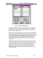
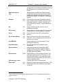
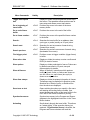
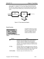
B loop
Triggers after B condition is met n (programmable) times
as set in Loop Count field.
A loop, then B
Triggers after A condition is met Loop Count times
followed by B condition (one time).
(A then B) loop
Triggers after (A followed by B) condition is met in turn
Loop Count times.
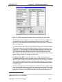
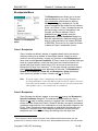
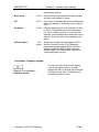
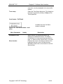
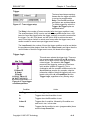
Filter
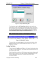
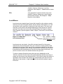
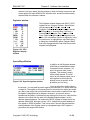
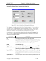
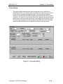
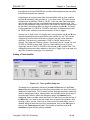
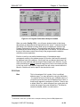
The Filter dialog box selects what frames are
captured. Only frames meeting the conditions
specified in the Filter field (see below) are
recorded in the trace buffer.
The Post View field sets the number of extra
bus cycles captured after each match of the
trace filter. The frame meeting the filter
parameter, and n more are recorded. This is
useful for recording multi-byte instructions. It is also very useful for recording a
few frames after a RTI (ReTurn from Interrupt) so that you may recognize the
code returned to.
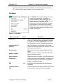
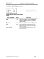
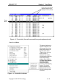
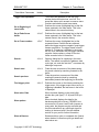
Figure 4–9. Trace filter setup
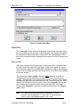
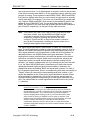
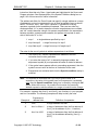
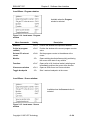
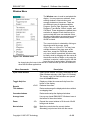
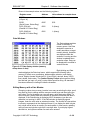
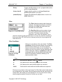
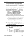
Filter Conditions:
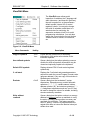
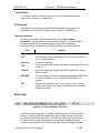
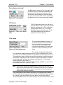
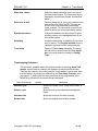
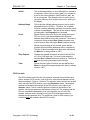
Figure 4–10. Filter
conditions
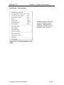
Filtering is a key feature of the trace board. The Filter
Conditions field controls what frames are recorded by
the trace board, allowing you to limit the captured
frames to only those in which you are interested. For
instance you may only wish to see the characters read
from the serial port. Setting a condition (A or B) and
enabling the filter for that condition(s) will reduce the
amount of information collected, and help you to
pinpoint problems faster.
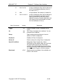
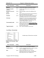
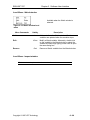
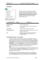
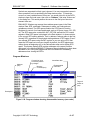
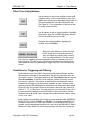
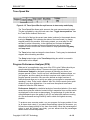
Filter:
Action:
All
All frames are captured. There is no filtering.
A
Only frames which match the A condition are recorded.
B
Only frames which match the B condition are recorded.
A&B
Frames which meet both A and the B conditions are captured.
Filtering is a key feature of the trace board. The Filter field controls what frames
are recorded by the trace board. Record filtering means that the trace buffer will
contain ONLY the records you are interested in. You may not need to visually
scan through thousands of records to find the one you want.
Copyright © 1997 ICE Technology
• 4–10