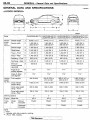
1
00-1
GENERAL
..........
%:
..
.-.
CONTENTS
... 32
Fuel Hoses . . . . . . . . . . . . . . . . . . . . . . . . . . . . . . . . .
44
..............3
............................
Ignition Cables . . . . . .
....................
Manual Transmission
....................
44
GENERAL DATA AND SPECIFICATIONS
HOW TO USE THIS MANUAL
Explanation of Manual Contents . . . . . . . . . . . . . . . 4
Maintenance. Repair and Servicing
Explanations .................................
3
............................
3
Special Tool Note
............................
.............................
3
Terms Definition
3
Model Indications
HOW TO USE TROUBLESHOOTING/
INSPECTION SERVICE POINTS
<From 1994 models>
...................... 6
LUBRICATION AND MAINTENANCE .......37
... 57
MAINTENANCE SERVICE ..................43
MAIN SEALANT AND ADHESIVE TABLE
Air Cleaner Element
Automatic Transmission Fluid
....
................
44
48
Ball Joint and Steering Linkage Seals . . . . . . . 51
Brake Hoses
110003838
....................
51
Spark Plugs ................................
SRS Maintenance ...........................
45
52
Timing Belt
. . . . . . . . . . . . . . . . . . 45
. . . . . . . . . . . . . . . . . . 43
.....
PRECAUTIONS BEFORE SERVICE
..........38
SCHEDULED MAINTENANCE TABLE ...... 40
TIGHTENING TORQUE ....................
36
TOWING AND HOISTING .................. 28
VEHICLE IDENTIFICATION .................13
............................
Distributor Cap and Rotor . . . . . . . . . . . . . . . . . . . 45
Drive Belt (For Water Pump and
Generator) . .
...........
. . . . . . 45
Engine Model Stamping
Theft Protection . . .
..
...........................
...........
52
49
........25
RECOMMENDED LUBRICANTS AND
LUBRICANT CAPACITIES TABLE
Chassis Number
Drive Shaft Boots
48
Rear Drum Brake Linings and
Rear Wheel Cylinders .......................
Disc Brake Pads . . . . . . . . . . . . . . . . .
Engine Coolant
45
Vehicle ldentificatio
..
18
. 19
............. 20
....... 13
Plate
Vehicle Identification Number List . . . . . . . . . . . . 14
Vehicle Identification Number Location . . . . . . . . 13
Vehicle Information Code Plate . . . . . . . . . . . . . . . 18
Engine Oil Filter
............................
47
Evaporative Emission Control System . . . . . . . . . 44
Exhaust System
............................
56
Vehicle Safety Certification Label
....
19
.
GENERAL- How to Use This Manual
00-3
HOW TO USE THIS MANUAL
110003839
MAINTENANCE, REPAIR AND
SERVICING EXPLANATIONS
This manual provides explanations, etc. concerning
procedures for the inspection, maintenance, repair
and servicing of the subject model. Unless otherwise
specified, each service procedure covers all models.
Procedures covering specific models are identified
by the model codes, or similar designation (engine
type, transaxle type, etc.). A description of these
designations is covered in this manual under “VEHICLE IDENTIFICATION”.
SERVICE ADJUSTMENT PROCEDURES
“Service Adjustment Procedures” are procedures
for performing inspections and adjustments of particularly important locations with regard to the construction and for maintenance and servicing, but other
inspections (for looseness, play, cracking, damage,
etc.) must also be performed.
SERVICE PROCEDURES
The service steps are arranged in numerical order
and attention must be paid in performing vehicle
service are described in detail in SERVICE POINTS.
TERMS DEFINITION
STANDARD VALUE
Indicates the value used as the standard for judging
the quality of a part or assembly on inspection or
the value to which the part or assembly is corrected
and adjusted. It is given by tolerance.
LIMIT
Shows the standard for judging the quality of a part
or assembly on inspection and means the maximum
or minimum value within which the part or assembly
must be kept functionally or in strength. It is a value
established outside the range of standard value.
REFERENCE VALUE
Indicates the adjustment value prior to starting the
work (presented in order to facilitate assembly and
adjustment procedures, and so they can be completed in a shorter time).
CAUTION
Indicates the presentation of information particularly
vital to the worker during the performance of maintenance and servicing procedures in order to avoid
the possibility of injury to the worker; or damage
to component parts, or a reduction of component
or vehicle function or performance, etc.
TIGHTENING TORQUE INDICATION
The tightening torque shown in this manual is a
basic value with a tolerance of *lo% except the
following cases when the upper and lower limits
of tightening torque are given.
(1) The tolerance for the basic value is within *lo%.
(2) Special bolts or the like are in use.
(3) Special tightening methods are used.
SPECIAL TOOL NOTE
Only MMC special tool part numbers are called out
in the repair sections of this manual. Please refer
to the special tool cross reference chart, which is
located in the service manual at the beginning of
each group, for a cross reference from the MMC
special tool number to the special tool number that
is available in your market.
MODEL INDICATIONS
The following abbreviations are used in this manual for classification of model types.
M E Indicates the manual transaxle, or models equipped with the manual transaxle.
A/T:
Indicates the automatic transaxle, or models equipped with the automatic transaxle.
MFI: Indicates the multiport fuel injection, or engines equipped with the multiport fuel injection.
ABS: Indicates the anri-lock braking system or models equipped with the anti-lock braking system.
1.5L Engine: Indicates the 1.5 dm3 (89.6 w i n . ) <4G15> engine, or a model equipped with such
an engine.
1.8L Engine: Indicates the 1.8 dm3 (111.9 cub) <4G93> engine, or a model equipped with such
an engine.
00-4
GENERAL- How to Use This Manual
EXPLANATION OF MANUAL CONTENTS
110000006
Indicates proceduresto be performed before
the work in that section is started, and procedures to be performed after the work in that
A diagram of the component parts is provided near the front of each section in order
to give the reader a better understanding of
the installed condition of component parts.
Indicates (by symbols) where lubrication is
1 necessary.
1
I
Maintenance and Servicing Procedures
The numbers provided within the diagram indicate the
sequence for maintenance and servicing procedures
Removal steps
The part designation number corresponds to the
number in the illustration to indicate removal
steps
s Disassembly steps
The part designation number corresponds to the
number in the illustration to indicate disassembly
steps
Installation steps:
Specified in case installation is impossible in reverse order of removal steps. Omitted if installation is possible in reverse order of removal steps.
Reassembly steps:
Specified in case reassembly is impossible in
reverse order of disassembly steps. Omitted if
reassembly is possible in reverse order of disassembly steps.
Classifications of Major Maintenance I Service Points
When there are major points relative to maintenance and servicing procedures (such as essential maintenance
and service points, maintenance and service standard values, information regarding the use of special tools, etc.),
these are arranged together as major maintenance and service points and explained in detail.
4 A F : Indicates that there are essential points for removal or disassembly.
F A q : Indicates that there are essential points for installation or reassembly.
Symbols for Lubrication, Sealants and Adhesives
Information concerning the locations for lubrication and
for application of sealants and adhesives is provided, by
using symbols, in the diagram of component parts or on
the page following the component parts page, and explained.
l
Grease
(multipurpose grease unless there is a
brand or type specified)
4:
a
Sealant
or adhesive
: 3 Brake fluid or automatic transmission fluid
:m
:
Engine oil, gear oil or air conditioning
compressor oil
:
Adhesive tape or butyl rubber tape
I
GENERAL
- How to Use This Manual
00-5
L
torque.
If there is no indication
of tightening torque,
refer to TIGHTENING
Denotes non-reusable
(Only very frequently used parts
are shown.)
I
37A-28
STEERING
-
Power Steering Gear Box
LUBRICATION AND SEALING POINTS
-
-
4
____ -
4onvenUonal wwer steering gear
_--
00x1
-
1
Automalis ti&%+
~ i o nl w d OEXRON II
Flyid
Operating procedures, cautions, etc. on removal, installation, disassembly and reassembly are described.
I
indicates that there is
continuity between the terrninals.
0-0
indicates terminals to
which battery voltage is applied.
I
The title of the page (following
the page on which the diagram
of component parts is presented) indicating the locations of
lubrication and sealing procedures.
00-6
How to Use Troubleshootingllnspection
Points <From 1994 models>
GENERAL - Service
HOW TO USE TROUBLESHOOTING/INSPECTlON SERVICE POINTS
s
<From 1994 models>
p;
110003842
rrc*l*
Troubleshooting of electronic control systems for which the scan tool can be used follows the basic outline
described below. Furthermore, even in systems for which the scan tool cannot be used, part of these
systems suu f d k w this W+J/,?,f%
TROUBLESHOOTING CONTENTS
1. STANDARD FLOW OF DIAGNOSTIC TROUBLESHOOTING
The main procedures for diagnostic troubleshooting are shown.
2. SYSTEM OPERATION AND SYMPTOM VERIFICATION TESTS
If verification of the trouble symptoms is difficult, procedures for checking operation and verifying trouble
symptoms are shown.
3. DIAGNOSTIC FUNCTION
The following diagnostic functions are shown.
0
Method of reading diagnostic trouble codes
0
Method of erasing diagnostic trouble codes
0
Input inspection service points
4. INSPECTION CHART FOR DIAGNOSTIC TROUBLE CODES
5. INSPECTION PROCEDURE FOR DIAGNOSTIC TROUBLE CODES
Indicates the inspection procedures corresponding to each diagnostic trouble code. (Refer to P.00-8
how to use the inspection procedures.)
6. INSPECTION CHART FOR TROUBLE SYMPTOMS
If there are trouble symptoms, even though the results of inspection using the scan tool show that
all diagnostic trouble codes are normal, inspection procedures for each trouble symptom will be found
by means of this chart.
7. INSPECTION PROCEDURE FOR DIAGNOSTIC SYMPTOM
Indicates the inspection procedures corresponding to each trouble symptoms classified in the Inspection
Chart for Trouble Symptoms. (Refer to P.00-8 - how to use the inspection procedures.)
8. SERVICE DATA REFERENCE TABLE
Inspection items and normal judgement values have been provided in this chart as reference information.
9. CHECK AT ECU TERMINALS
Terminal numbers for the ECU connectors, inspection items and standard values have been provided
in this chart as reference information.
-
4
Terminal Voltage Checks
1. Connect a needle-nosed wire probe or paper clip to a voltmeter probe.
2. Insert the needle-nosed wire probe into each of the ECU connector terminals from the wire side,
and measure the voltage while referring to the check chart.
NOTE
1. Measure voltage with the ECU connectors connected.
2. You may find it convenient to pull out the ECU to make it easier to reach the connector terminals.
3. Checks don't have to be carried out in the order given in the chart.
Caution
'
Short-circuitingthe positive (+) probe between a connector terminal and ground could damage
the vehicle wiring, the sensor, the ECU, or all three.
Use care to prevent this!
3. If voltage readings differ from Normal Condition values, check related sensors, actuators, and
wiring, then replace or repair.
4. After repair or replacement, recheck with the voltmeter to confirm that the repair has corrected
the problem.
How to use Troubleshootingllnspectlon
1994 models>
GENERAL - Service Points <From
00-7
Terminal Resistance and Continuity Checks
1. Turn off the ignition switch.
2. Disconnect the ECU connector.
3. Measure the resistance and check for continuity between the terminals of the ECU harness-side
connector while referring to the check chart.
'
NOTE i.c.17 *
Checks don't have to be carried out in the order given in the chart.
Caution
If resistance and contlnuity checks are performed on the wrong terminals, damage to the
vehicle wiring, sensors, ECU, and/or ohmmeter may occur.
Use care to prevent this!
4. If the ohmmeter shows any deviation from the Normal Condition value, check the corresponding
sensor, actuator and related electrical wiring, then repair or replace.
5. After repair or replacement, recheck with the ohmmeter to confirm that the repair has corrected
the problem.
10. INSPECTION PROCEDURES USING AN OSCILLOSCOPE
When there are inspection procedures using an oscilloscope, these are listed here.
00-8
GENERAL
How to Use Troubleshooting/lnspection
- Service Points <From 1994 models>
HOW TO USE THE INSPECTION PROCEDURES
110000009
The causes of a high frequency of problems occurring in electronic circuitry are generally the connectors,
components, the ECU and the harnesses between connectors, in that order. These inspection procedures
follow this order, and they first try to discover a problem with a connector or a defective component.
HARNESS INSPECTION
Check for an open or short circuit in the harness between the terminals which were defective according
to the connector measurements. Carry out this inspection while referring to Volume 2 Electrical manual.
Here, "Check harness between power supply and terminal xx" also includes checking for blown fuses.
For inspection service points when there IS a blown fuse, refer to "Inspection Service Points for a Blown
Fuse".
MEASURES TO TAKE AFTER REPLACING THE ECU
': the trouble symptoms have not disappeared even after replacing the ECU, repeat the inspection procedure
"-71 the beuinnina.
- How to Use Troubleshootingllnspection
1994 models>
00-9
GENERAL Service Points <From
CONNECTOR MEASUREMENT SERVICE POINTS
110000010
Turn the ignition switch to OFF when connecting and disconnecting the connectors, and turn the ignition switch to ON
when measuring if there are no instructions to the contrary.
IF INSPECTING WITH THE CONNECTOR CONNECTED
(WITH CIRCUIT IN A CONDITION OF CONTINUITY)
Waterproof Connectors
Be sure to use the special tool (harness connector). Never
insert a test probe from the harness side, because to do so
will reduce the waterproof performance and result in corrosion.
Harness connector
Ordinary (non-waterproof) Connectors
Check by inserting the test probe from the harness side. Note
that if the connector (control unit, etc.) is too small to permit
insertion of the test probe, it should not be forced; use a
special tool (the extra-thin probe in the harness set forchecking)
for this purpose.
IF INSPECTING WITH THE CONNECTOR DISCONNECTED
<When Inspecting a Female Pin>
Use the special tool (inspection harness for connector pin
contact pressure in the harness set for inspection).
The inspection harness for connector pin contact pressure
should be used. The test probe should never be forcibly inserted, as it may cause a defective contact.
Inspection harness
for connector pin
contact pressure
ZOlROS70
<When Inspecting a Male Pin>
Touch the pin directly with the test bar.
Caution
c
At this time, be careful not to short the connector pins
with the test probes. To do so may damage the circuits
inside the ECU.
I
Y
H
I
-
/
How to Use Troubleshootingllnspectlon
Points <From 1994 models>
GENERAL - Service
00-10
Connector disconnected or improperly
connected
CONNECTOR INSPECTION SERVICE POINTS
110000011
VISUAL INSPECTION
0
Connector is disconnected or improperly connected
0
Connector pins are pulled out
0
Due to harness tension at terminal section
0
Low contact pressure between male and female terminals
0
Low connection pressure due to rusted terminals or foreign
matter lodged in terminals
L
ZlBS0256
Defective connector contact
/
/
section
Low contact pressure
CONNECTOR PIN INSPECTION
If the connector pin stopper is damaged, the terminal connections (male and female pins) will not be perfect even when
the connector body is connected, because the pins may pull
out of the back side of the connector. Therefore, gently pull
the wires one by one to make sure that no pins pull out of
the connector.
CONNECTOR ENGAGEMENT INSPECTION
Use the special tool (connector pin connection pressure inspection harness of the inspection harness set) to inspect the engagement of the male pins and female pins. [Pin drawing
force : 1 N (.2Ibs.) or more]
GENERAL
How to Use Troubleshootlngllnspection
- Service
Points <From 1994 models>
HOW TO COPE WITH INTERMITTENT MALFUNCTIONS
00-11
110000012
Most intermittent malfunctions occur under certain conditions. If those conditions can be identified, the
cause will be easier to find.
TO COPE WITH INTERMllTENT MALFUNCTION;
1. Ask the customer about the malfunction
Ask what it feels like, what it sounds like, etc.
Then ask about driving conditions, weather, fret
quency of occurrence, and so on.
L
2. Determine the conditions from the customer’s responses
Typically, almost all intermittent malfunctions
. occur from conditions like vibration, temperature
:- and/or moisture change, poor connections.
From the customer’s replies, it should be reasoned which condition is influenced.
duplicate the customer’s complaint. Determine
the most likely circuit(s) and perform the simulation tests on the connectors and parts of that
circuit(s). Be sure to use the inspection procedures provided for diagnostic trouble codes and
trouble symptoms.
For temperature and/or moisture conditions related intermittent malfunctions, using common
sense, try to change the conditions of the suspected circuit components, then use the simulation tests below.
I
3.
Use simulation test
In the cases of vibration or poor connections,
use the simulation tests below to attempt to
21ES0253
21850252
4. Verify the intermittent malfunction is eliminated
Repair the malfunctioning part and try to duplicate the condition(s) again to verify the intermittent malfunction has been eliminated.
SIMULATION TESTS
For these simulation tests, shake, then gently bend, pull, and
twist the wiring of each of these examples to duplicate the
intermittent malfunction.
0
Shake the connector up-and-down, and right-and-left.
0
Shake the wiring harness up-and-down, and right-and-left.
0
Vibrate the part or sensor.
NOTE
In case of difficulty in finding the cause of the intermittent
malfunction, the data recorder function in the scan tool (MUT-II)
is effective.
00-12
GENERAL
How to Use Troubleshootingllnspectlon
- Service
Points <From 1994 models>
INSPECTION SERVICE POINTS FOR A BLOWN
FUSE
110000013
Remove the fuse and measure the resistance between the
load side of the fuse and ground. Set the switches of all circuits
which are connected to this fuse to a condition of continuity.
If the resistance is almost 0 R at this time, there IS a short
somewhere between these switches and the load. If the resistance is not 0 R, there is no short at the present time, but
a momentary short has probably caused the fuse to blow.
The main causes of a short circuit are the following.
0
Harness being clamped by the vehicle body
0
Damage to the outer casing of the harness due to wear
or heat
0
Water getting into the connector or circuitry
0
Human error (mistakenly shorting a circuit, etc.)
ZlSX0370
-
GENERAL Vehicle Identification
00-13
V EH I CLE I DENTIFICAT10 N
VEHICLE IDENTIFICATION NUMBER LOCATION
110000014
The vehicle identification number (V.I.N.) is located on a plate
attached to the left top side of the instrument panel.
VEHICLE IDENTIFICATION CODE CHART PLATE
4 9 9 3 MODELS
I10003843
All vehicle identification numbers contain 17 digits. The vehicle
number is a code which tells country, make, vehicle type,
etc.
No.
1. 2 3
5 '6 '7 '8'9.10-11-12
4
AOOS0165
4 9 9 4 MODELS>
1
/ii \ \N
\\\
2
3
Items
I
Contents
1
Country
J: Japan
2
Make
A: Mitsubisht
3
Vehicle type
3: Passenger car
4
Others
A. Driver and passenger air bags
5
Line
6
Price class
4 5 6 7 8 9 1 0 1 1 12
I
1 A: Mirage
1 1: Economy
I
I
I
I
2: Low
3: Medium
A0050166
I <From
4: High
1: 2-door sedan
7
I
1995 MODELS>
6: 4-dOOr sedan
8
A: 1.5 dm3 (89.6 c u h . )
[SOHC-MFI-12 valve*2]
Engine
' C: 1.8 dm3 (111.9 cub)
I
ii I \\\
2
3
4
5
~
6
9101112
7 8
Check dioits*l
9
__
Model year
10
1
1
12 3 4 5 6 7 8 9 X
R: 1994 year
1 S: 1995 year
11
1
I
P: 1993 year
AOOS0167
'
ISOHC-MFI-16 ~ a l v e ' ~ 1
T 1996 year
U: Mizushima plant
Plant
Serial number
12
-
1
I
I
I
000001 to 999999
NOTE
(1)*1: Check digit means a single number or letter X used to verify the
accuracy of transcription of vehicle identification number.
(2)*2: 2 intake valves and 1 exhaust valve per cylinder
(3)*3:2 intake valves and 2 exhaust valves per cylinder
GENERAL - Vehicle Identification
00-14
VEHICLE IDENTIFICATION NUMBER LIST
110003844
V.I.N. (except sequence number)
Brand
Engine displacement
JA3CAIlAOPU
Mirage
1.5 dm3 (89.6 cub)
[SOHC-MFI-12 valve*]
JA3CA21AOPU
~
.-
Models code
' CA2ADNS EL2M
'
CA2ADNMEL2M/KMEL2M
CA2ADNDEL2M/KDEL2M
JA3CA31AOPU
V.I.N. (except sequence number)
Brand
Engine displacement
Models code
JA3CAll AOPU
Mirage
1.5 dm3 (89.6 cu.in.)
[SOHC-MFI-12 valve*]
CA2ADNSEL7M
JA3CA21AOPU
CA2ADNMEL7M/KMEL7M
CA2ADNDEL7MIKDEL7M
JA3CA31AOPU
I V.I.N. (except sequence number) 1 Brand
Mirage
JA3CA26AOPU
I
I
JA3CA36AOPU
I Engine displacement
1.5 dm3 (89.6 cu.in,)
[SOHC-MFI-l2 valve*l]
I
1
Models code
CB2ASNDEL2M/KDEL2M
I
1.8 dm3 (111.9 cu,in,)
[SOHC-MFI-16 valve**]
JA3CA46COPU
CB2ASNMEL2M/KMEL2M
CB5ASNJEL2M/RJEL2M
1
NOTE
intake valves and 1 exhaust valve per cylinder
**: 2 intake valves and 2 exhaust valves per cylinder
*l:
2
V.I.N. (except sequence number)
Brand
Engine displacement
Models code
Mirage
1.5 dm3 (89.6 cu.ln.)
[SOHC-MFI-12 valve*l]
CB2ASNMEL7M/KMEL7M
1.8 dm3 (111.9 cu,in,)
WHC-MFI-16 valve**]
CB5ASNDEL7MIRDEL7M
CB5ASNJEL7M,RJ EL7M
JA3CA36AOPU
I
JA3CA46COPU
I
GENERAL - Vehicle Identification
00-15
c1994 MODELS>
2-DOOR MODELS FOR FEDERAL
I V.I.N. (except sequence number) 1 Brand
JA3EAl1 AORU
Mirage
JA3EA21ADRU
JA3EA31AORU
1 Engine displacement 1 Models code
1.5 dm3 (89.6 c u m )
[SOHC-MFI-l2 valve*l]
CA2ADNSEL2M
CA2ADNMEL2MlKMEL2M
'1
..
-.-
CA2ADNDEL2M/KDEL2M
.$
JA3EA31CORU
1.8 dm3 (111.9 cu.in.)
[SOHC-MFI-l6 valve*2]
V.I.N. (except sequence number)
I JA3EA11AORU*3
I JA3EA21AORU*3
I
Brand
1 Mirage
I
CASADNDEL2M/RDEL2M
I Engine displacement
1
11
1 CA2ADNSEL7M
1.5 dm3 (89.6 cu.in.)
[SOHC-MFI-12 valve*l]
~
Models code
I
CA2ADNMEL7MlKMEL7M
NOTE
*l: 2 intake
*2: 2 intake
*3 can also
valves and 1 exhaust valve per cylinder
valves and 2 exhaust valves per cylinder
be sold in Federal States.
V.I.N. (except sequence number)
Brand
Engine displacement
Models code
JA3EA26AORU
Mirage
1.5 dm3 (89.6 cu.in.)
[SOHC-MFI-12 valve*l]
CB2ASNMEL2M/KMEL2M
JA3EA36AORU
JA3EA36CORU
1.8 dm3 (111.9 cu.in.)
[SOHC-MFI-16 valve*2]
JA3EA46CORU
1
CB2ASKDEL2M
CB5ASNDEL2MIRDEL2M
1
CB5ASRJEL2M
NOTE
intake valves and 1 exhaust valve per cylinder
intake valves and 2 exhaust valves per cylinder
'I: 2
*2: 2
r
4-DOOR MODELS FOR CALIFORNIA
I V.I.N. (except sequence number) 1
JA3EA26AU
Brand
I
Mirage
1
I
NOTE
*': 2 intake valves and 1 exhaust valve per cylinder
*2: 2 intake valves and 2 exhaust valves per cylinder
*3 can also be sold in Federal States.
I
I Engine displacement I Models code
CB2ASNMEL7M/KMEL7M
-~
1.5 dm3 (89.6 cu.in.)
[SOHC-MFI-12 valve*']
JA3EA36ACRU*3
I JA3EA46CORU*3
.*-I)
I
I
[SOHC-MFI-16 valvk2]
~
I
CB5ASRJEL7M
I
3
00-16
GENERAL - Vehicle Identification
4 9 9 5 MODELS>
2-DOOR MODELS FOR FEDERAL
V.I.N. (except sequence number)
Brand
Engine displacement
JA3AAl1AOSU
Mirage
1.5 dm3 (89.6 cu.ln.)
[SOHC-MFI-l2 valve*1]
JA3AA21AUSU
1
Models code
CA2ADNSEL2M/KSEL2M
-
CA2ADNMEL2M/KMEL2M
CA2ADNDEL2M/KDEL2M
JA3AA31ACSU
1.8 dm3 (111.9 cu.in.)
CA5ADNDEL2MIRDEL2M
[SOHC-MFI-16 ~ a l v e ’ ~ ]
NOTE
* l : 2 intake valves and 1 exhaust valve per cylinder
*? 2 intake valves and 2 exhaust valves per cylinder
2-DOOR MODELS FOR CALIFORNIA
I V.I.N. (except sequence number) 1 Brand
JA3AA11AOSU*3
i Engine displacement 1 Models code
Mirage
1.5 dm3 (89.6 cu.[n.)
[SOHC-MFI-12 valve*’]
JA3AA21AOSU*3
JA3AA31COSU*3
1.8 dm3 (111.9 cum.)
[SOHC-MFI-16 valve’*]
I
CA2ADNSEL7MIKSEL7M
CA2ADNMEL7MIKMEL7M
1
CA5ADNDEL7fWRDEL7M
4-DOOR MODELS FOR FEDERAL
I V.I.N. (except sequence number) 1 Brand
I JA3AA26AOSU
I Mirage
I JA3AA36AOSU
i
I
I JA3AA36COSU
I JA3AA46COSU
V.I.N. (except sequence number)
Brand
1
I Engine displacement
1 Models code
1.5 dm3 (89.6 cu.in.)
[SOHC-MFI-12 valve*1]
1
[SOHC-MFI-16 valv&]
~
CBSASRJ EL2M
Engine displacement
Models code
1.8 dm3 (111.9 cu.in.)
[SOHC-MFI-16 valve*2]
CB5ASNDEL7M/RDEL7M
Mirage
JA3AA36ACSU*3
NOTE
* l : 2 intake valves and 1 exhaust valve per cylinder
*2: 2 intake valves and 2 exhaust valves per cylinder
*3 can also be sold in Federal States.
I
GENERAL
- Vehicle Identification
00-I?
_ _
4 9 9 6 MODELS>
2-DOOR MODELS FOR FEDERAL
V.I.N. (except sequence number)
I
JA3AAll AOTU
1 Mirage
Brand
Engine displacement
1.5 dm3 (89.6 cu.in.)
[SOHC-MFI-12 valve*l]
JA3AA21AOTU
JA3AA31AOTU
I
1
Models code
I
CA2ADNMEL2MIKMEL2M
1. CA2ADNDEL2MIKDEL2M I
.
I
1.8 dm3 (111.9 cu.in.)
[SOHC-MFI-16 valve*2]
JA3AA31CnTU
CA5ADNDEL2M/RDEL2M
NOTE
* l : 2 intake valves and 1 exhaust valve per cylinder
**: 2 intake valves and 2 exhaust valves per cylinder
2-DOOR MODELS FOR CALIFORNIA
I V.I.N. (except sequence number) 1 Brand
I JA3AAll AOTU*3
1 Mirage
I
I
JA3AA21AOTU*3
1 Engine displacement
1.5 dm3 (89.6 cu.in.)
[SOHC-MFI-12 valve*l]
JA3AA31COTU*3
1.8 dm3 (111.9 cu.in.)
[SOHC-MFI-16 valve*2]
Models code
I
CA2ADNMEL7M/KMEL7M
CA5ADNDEL7M/RDEL7M
NOTE
* I : 2 intake valves and 1 exhaust valve per cylinder
*2: 2 intake valves and 2 exhaust valves per cylinder
*3 can also be sold in Federal States.
4-DOOR MODELS FOR FEDERAL
I V.I.N. (except sequence number)
Brand
1
Mirage
~
JA3AA36AOTU
JA3AA36CUTU
Engine displacement
1.5 dm3 (89.6 cu.in.)
[SOHC-MFI-12 valve'l]
1.8 dm3 (111.9 cum.)
[SOHC-MFI-16valve*2]
JA3AA46COTU
1 Models code
I
1 CB2ASKDEL2M
I
CB5ASRJEL2M
4-DOOR MODELS FOR CALIFORNIA
V.I.N. (except sequence number)
1 JA3AA26AOTU*3
Brand
1 Mirage
NOTE
*I: 2 intake
*2: 2 intake
*3 can also
valves and 1 exhaust valve per cylinder
valves and 2 exhaust valves per cylinder
be sold in Federal States.
i
Engine displacement
Models code
1.5 dm3 (89.6 cu.in.)
[SOHC-MFI-l2 valve*l]
CB2ASNMEL7M/KMEL7M
GENERAL - Vehicle Identification
00-18
VEHICLE INFORMATION CODE PLATE
110003845
Vehicle information code plate is riveted onto the bulkhead
in the engine compartment.
The place shows model code, engine model, transaxle model,
and body color code.
No.
Items
Contents
1
MODEL
CA2ADNSEL2M
2
ENGINE
4G15
Engine model
3
EXT
CAGA
Exterior code
4
TRANS
AXLE
F5M21
Transaxle model
CAPADN: Vehicle model
SELZM: Model series
I
'
J
ZOOBOrUl6
I
I
OPT
87V: Interior code
03V: Equipment code
CHASSIS NUMBER
I10003846
STAMPING LOCATION
The chassis number is stamped on the top center of the firewall
located in the engine compartment.
-
00-19
GENE ?AL Vehicle Identification
VEHICLE SAFETY CERTIFICATION LABEL
110000019
1. The vehicle safety certification label is attached to the
face of left door pillar.
2. This label indicates the month and year of manufacture,
Gross Vehicle Weight Rating (G.V.W.R.), Gross Axle
Weight Rating (G.A.W.R.) front and rear and Vehicle Identification Number (V.I.N.).
-
%
.
a
s
ENGINE MODEL STAMPING
110003847
1. The engine model number is stamped at the front side
on the top edge of the cylinder block as shown in the
following:
I
I
I
I Engine displacement
Engine model
4G15
4G93
Engine serial number
I
1.5 dm3 (89.6 cu.in.)
ISOHC-MPI-12valve1
1.8 dm3 (111.9 cu.in.)
[SOHC-MPI-16valve]
1
AA0201 to YY9999
I
GENERAL - Vehicle Identification
00-20
THEFT PROTECTION <From 1994 models>
Theft protection label
I10003848
For original parts
ZoOK619
For replacement parts
F
IRADOT]
I
\
I
ZOOK621
In order to protect against theft, a Vehicle Identification Number
(V.I.N.) is stamped in, or attached as a label to, the following
major parts of the engine and transaxle, as well as main outer
panels:
Engine cylinder block, Transaxle housing, Fender, Door, Quarter panel, Hood, Trunk lid, Bumpers
In addition, a theft-protection label is attached to replacement
parts for the body outer panel main components, and the
same data are stamped into replacement parts for the engine
and the transaxle.
Cautions regarding panel repairs:
1. When repaintlng original parts, do so after first masking the theft-protection label, and, after painting, be
sure to peel off the masking tape.
2. The theft-protection label for replacement parts is covered by masking tape, so such parts can be painted
as is. The masking tape should be removed after painting is finished.
3. The theft-protection label should not be removed from
original parts or replacement parts.
LOCATIONS
Part
1 Target area (A: for original equipment parts, B: for replacement parts)
Engine
1.8L Engine
AOlS0205
GENERAL - Vehicle Identification
Part
Transaxle
00-21
Target area (A: for original equipment parts, 8:for replacement parts)
Manual transaxle
<F5M211F5M22>
Automatic transaxle
<F3A211F4A22>
B
A
A04S0083
A09S0084
Fender
B
The illustration indicates left hand side, outer.
Right hand side is symmetrically opposite.
Front door
A1850442
<2 door model>
<4 door model>
A
The illustration indicates left hand side, outer.
Right hand side is symmetrically opposite.
A0050132
-
00-22
GENERAL Vehicle Identification
Target area (A: for original equipment parts, B: for replacement parts)
Part
1 <4 door model>
I Reardoor
C'
,',
A
-B
AOOS0131
The illustration indicates left hand side, outer.
Right hand side is symmetrically opposite.
:2 door model>
Quarter panel
The label is attached
at the inner side of
the parts shown in the
fiaure.
B
AOOS0164
The illustration indicates left hand side, outer.
Right hand side is symmetrically opposite.
I
GENERAL
- Vehicle
00-23
Identification
'art
I Target area (A: for original equipment parts, B: for replacement parts)
h a r t e r panel
1 c4 door model>
The label is attached
at the inner side of
the parts shown in the
figure.
B
The illustration indicates left hand side, outer.
Right hand side is symmetrically opposite.
A0050163
iood
AlBS0441
Trunk lid
AOOS0130
-
00-24
GENERAL Vehicle Identification
I Part
1
I Front bumper
I
Target area (A: for original equipment parts, B: for replacement parts)
u
AOOS0128
I-
Rear bumper
\\\'
AOOSO129
GENERAL - Precautions before Service
PRECAUTIONS BEFORE SERVICE
00-25
110003849
SUPPLEMENTAL RESTRAINT SYSTEM (SRS) <From 1994 models>
1. Items to follow when servicina SRS
(1) Be sure to read GROUP-52B - Supplemental Restraint System (SRS).
For safe operations, please follow the directions and heed all warnings.
(2) Always use the designated special tools and test equipment.
(3) Wait at least 60 seconds after disconnecting the battery cable before doing any further work.
The SRS system is designed to retain enough voltage to deploy the air bag even after the battery
has been disconnected. Serious injury may result from unintended air bag deployment if work
is done on the SRS system immediately after the battery cable is disconnected.
(4) Never attempt to disassemble or repair the SRS components (front impact sensors, SRS air bag
control unit, air bag module and clock spring). If faulty, replace it.
(5) Warning labels must be heeded when servicing or handling SRS components. Warning labels
are located in the following locations.
0
Hood
0
Sun visor
0
Glove box
0
SRS air bag control unit
0
Steering wheel
0
Air bag module
0
Clock spring
0
Steering gear and linkage clamp
(6) Store components removed from the SRS in a clean and dry place.
The air bag module should be stored on a flat surface and placed so that the pad surface is
facing upward.
Do not place anything on top of it.
(7) Be sure to deploy the air bag before disposing of the air bag module or disposing of a vehicle
equipped with an air bag. (Refer to GROUP 526 - Air Bag Module Disposal Procedures.)
(8) Whenever you finish servicing the SRS, check the SRS warning light operation to make sure
that the system functions properly.
Observe the following when carrying out operations on places where SRS components are installed,
including operations not directly related to the SRS air bag.
(1) When removing or installing parts do not allow any impact or shock to the SRS components.
(2) SRS components should not be subjected to heat over 93°C (200°F), so remove the SRS components
before drying or baking the vehicle after painting.
After re-installing them, check the SRS warning light operation to make sure that the system functions
properly.
I
00-26
GENERAL
- Precautions before Service
SERVICING ELECTRICAL SYSTEM
110000023
1. Note the following before proceeding with work on the
electrical system.
Note that the following must never be done:
Unauthorized modifications of any electrical device or wiring, because such modifications might lead to a vehicle
malfunction, over-capacity or short-circuit that could result
in a fire in the vehicle.
2. When servicing the electricat system, disconnect the negative cable terminal from the battery.
Caution
1. Before connecting or disconnecting the negative
cable, be sure to turn off the ignition switch and
the lighting switch.
(If this is not done, there is the possibility of semiconductor parts being damaged.)
2. After completion of the work steps [when the battery’s negative (-) terminal is connected], warm
up the engine and allow it to idle for approximately
ten minutes under the conditions described below,
In order to stabilize the engine control conditions,
and then checkto be sure that the idling is satisfactory.
Engine coolant temperature: 85-95°C (185-203°F)
Lights, electric fans, accessories: OFF
Transaxle: Neutral position
(A/T models: “N” or “P”)
Steering wheel: neutral (center) position
VEHICLE WAS HING
110000024
If high-pressure car-washing equipment or steam car-washing
equipment is used to wash the vehicle, be sure to maintain
the spray nozzle at a distance of at least 300 mm (12 in.)
from any plastic parts and all opening parts (doors, luggage
compartment, etc.).
mm (in.)
zmsom
APPLYING RUST PREVENTIVES, UNDERCOAT,
ETC.
Heated oxygen sensors have their functional efficiency
decreased if they are smeared with oil or grease. When
applying rust preventives, undercoat, etc., be sure to protect
the heated oxygen sensor with a protective cover or the like.
GENERAL
Scan tool (Multi-use tester <MUT>)
- Precautions before Service
00-27
SCAN TOOL (MUT) <Up to 1993 models>
110003850
(1) To operate the scan tool, refer to the “Multi-use Tester
Operation Instructions”.
?OM pack
ROM pack
Applicable Model
MB991466
1993 model
Scan
SCAN TOOL (MUT-II) <All models>
ROM
To operate the scan tool, refer to the “MUT-II OPERATING
INSTRUCTIONS”.
Caution
Connection and disconnection of the scan tool should
always be made with the ignition switch in the OFF position.
R
110003851
00-28
GENERAL - Towing and Hoisting
TOWING AND HOISTING
Sling type
110003852
WRECKER TOWING RECOMMENDATION
FRONT TOWING PICKUP
Caution
This vehicle cannot be towed by a wrecker using sling-type
equipment to prevent the bumper from deformation.
If this vehicle is towed, use wheel lift or flat bed equipment.
The vehicle may be towed on its rear wheels for extended
distances provided the parking brake is released. It is recommended that vehicles be towed using the front pickup whenever
possible.
Wheel lift type
Flat bed type
ZOOFW27
I
Sling type
Wheel lift type
Flat bed type
I
I
REAR TOWING PICKUP
Caution
This vehicle cannot be towed by a wrecker using sling-type
equipment to prevent the bumper from deformation.
If this vehicle is towed, use wheel lift or flat bed equipment.
Manual transaxle vehicles may be towed on the front wheels,
provided the transaxle is in neutral and the drive-line has
not been damaged. The steering wheel must be clamped
in the straight-ahead position with a steering wheel clamping
device designed for towing service use.
Caution
1. Do not use steering column lock to secure front wheel
position for towing.
*2. Make sure the transaxle is in Neutral if vehicle will
be with drive wheels on the ground.
Automatic transaxle vehicle may be towed on the front wheels
at speeds not to exceed 50 km/h (30 mph) for distances not
to exceed 30 km (18 miles).
Cautlon
If these limits cannot be met, the front wheels must be
placed on a tow dolly.
NOTE
*: <From 1994 models>
TOWING WHEN KEYS ARE NOT AVAILABLE
When a locked vehicle must be towed and keys are not available, the vehicle may be lifted and towed from the front, provided the parking brake is released. If not released, the rear
wheels should be placed on a tow dolly.
-
GENERAL Towing and Hoisting
Frame contact support location
d-door models>
-
1,190 mm (46.9 in.)
ZOOS0082
e4-door models>
: j
00-29
SAFETY PRECAUTIONS
The following precautions should be taken when towing the
vehicle.
1. DO NOT LIFT OR TOW THE VEHICLE BY ATTACHING
TO OR WRAPPING AROUND THE BUMPER.
2. Any loose or protruding parts of damaged vehicle such
as hoods, doors, fenders, trim, etc., should be secured
or removed prior to moving the vehicle.
3. Operator should refrain from going under a vehicle while
it is lifted by the towing equipment, unless the vehicle
is adequately supported by safety stands.
4. Never allow passengers to ride in a towed vehicle.
5 . State and local rules and regulations must be followed
when towing a vehicle.
u
1,219 rnm (48.0 in.)
2wsoo81
HOISTING
U
H-bar lift
ZOOR0157
i
f
‘i
I
Chassis-support position
(side sill)
/ Attatchment
I
L
H-bar lift
Attachment
ZOOU0113
POST TYPE
Special care should be taken when raisig the vehicle on a
frame contact type hoist. The hoist must be equipped with
the proper adapters in order to support the vehicle at the
proper locations.
Caution
When service procedures require removing rear suspension, fuel tank, spare tire and lift gate, place additional
weight on rear end of vehicle or anchor vehicle to hoist
to prevent tipping or center of gravity changes.
When H-bar lift is used to lift up vehicles, use of metallic
attachment attached to the H-bar lift may cause damage to
the suspension arm etc. Therefore, lift up the vehicle by the
following procedure.
(1) Place the vehicle on the H-bar lift (same direction).
(2) Place attachments on the H-bar lift at the designated chassis-support positions. When making the attachmets, refer
to the section concerning making them.
Caution
If support is at any location other than the designated
positions, the body or suspension might be deformed
or otherwise damaged, so care shoud be taken to
support only at the correct (designated) positions.
(3) Raise the H-bar lift to the height at which the vehicle
is slightly raised and check to be sure that the vehicle
is correctly and sufficiently secured; then raise the vehicle.
GENERAL - Towing and Hoisting
00-30
mm (in.)
Block (A)
“ATTACHMENTS” PREPARATION
(1) Prepare the blocks (wooden) and nails as shown in the !
figure.
Item
(3.74)
w-
I
I Dimensions mm (in.)
1 Q’tY
Block (C)
Block ( 6 )
1 (5.51 X 1.57 X 3.74)
~
Nail
100 (3.93)
Block
Caution
The wood selected for the blocks must be hard.
(2) For the (B)blocks and (C) blocks, use a saw and chisel
or similar tool to make grooves of the dimensions shown
in the figure.
(3) Make four “ATTACHMENTS” such as shown in the figure,
nailing (B) and (C) blocks so that each (B) block is sandwiched between (C) blocks.
Y
100 (3.93)
140
70 (2.76) or more
Block (C)
Nail
(5.51
Block (B)
ZOOUOH
Finished attachment
FLOOR JACK
A regular floor jack may be used under the mid point of center
member, or the jack up bracket under the rear floor pan.
Caution
1. Never use a jack at the rear floor crossmember or
rear suspension assembly.
2. In order to prevent scarring the center member, place
a piece of cloth on the jack’s contact surface (to prevent corrosion caused by damage to the coating).
3. A floor jack must never be used on any part of the
_ - .
underbody.
1 TSB Revision
GENERAL - Towing and Hoisting
00-31
Do not attempt to raise one entlre side of the vehicle
by placing a jack midway between front and rear
wheels.
This practice may result in permanent damage to the
body.
4.
~~
~
EMERGENC' JACKING
Jack receptacles are located at the body sills to accept the
scissors jack supplied with the vehicle for emergency road
service. Always block opposite wheels and jack on level surface.
LIFTING, JACKING SUPPORT LOCATION
110003853
t
i
ZODS0011
Floor jack locations
@
.-
-@-
Approximate center of gravity
Frame contact hoist, twin post hoist or scissors jack (emergency) locations
Caution
0
Never use a jack at the rear crossmember or rear suspension assembly.
0
In order to prevent scarring the center member, place a piece of cloth on the jack's
contactsurface (to prevent corrosion caused by damage to the coating).
0
Never attempt to position a floor jack on any part of the vehicle underbody.
0
Do not attempt to raise one entire side of the vehicle by placing a jack midway between
the front and rear wheels. To do so could result in permanent damage to the body.
GENERAL - General
00-32
Data and Sbecifications
GENERAL DATA AND SPECIFICATIONS
110003854
<2-DOOR MODELS>
1 CMADNSEEMPM ICA2ADKMEEWM
CA2ADNMEUMPM 1 CA2ADNDEEMRM CA5ADNDEWM*2/7M*2
CMADKDEEMRM ICA5ADRDEEM'2/7M*'
tems
1
lehicle Overall length
Iimen;ions
Overall width
nm (in.)
1
12
4,345 (171.1)
4,345 (171.1)
4,345 (171.1)
4,345 (171.1)
1,680 (66.1)
1,690 (66.5)*l
1,680 (66.1)
1,690 (66.5)*'
1,680 (66.1)
1,690 (66.5)*l
1,680 (66.1)
1,690 (66.5)*l
bvezheight
13 1
1,360 (53.5)
1
'Wheel base
14 1
2,440 (96.1)
5
1,450 (57 1)
1
2,440 (96.1)
1
1
I
1.460 (57.5)
I
1.460 (57.5)
I Tread - Front
1 Tread - Rear
1 Overhang - Front
'Overhang-Rear
I Minimum
running ground
clearance
1 Angle of ap-
16
1
( 81
~
7
I
1
860 (33.9)
1,045(41.1)
150(5'9)
17.7"
1
1
!
~
I
1
1,360 (53.5)
1,450 (57.1)
.
860 (33.9)
1,045(41.1)
1
11
I
17.7"
weiqht rating
Fngine
rransixle
1 Model No.
' Model
~
I
NO.
830(1,830)
790 (1,742)
I
Seating capacity
'
1
Manual
transaxle
1,360 (53.5)
I
2,440 (96.1)
1,450 (57.1)
!
1,460 (57.5)
860 (33.9)
1,045(41.1)
5
4G15
1
1
I
1
F5M21
-
Automatic
transaxle 1
1
1
1
150 (5.9)
1
17.7"
I
995750(:2~~2~r
830(1,830)
1
965 (2,127) or
980 (2,l 61)*
1
830(1,830)
860 (33.9)
1,045(41.1)
1
1
17.7"
17.4"
1,020 (2,249) or
1,035 (2,282)*
I
790 (1,742)
790 (1,742)
790 (1,742)
5
5
5
4G15
1
4G15
I
4G93
F5M21
F5M21
F5M22
F3A21
F3A21
F4A22
NOTE
*: em>
'l: Vehicles with side protector molding
*2: <From 1994 models>
1 TSB Revision
1,450 (57.1)
1,460 (57.5)
150 (5.9)
I
I
i
~
1
17.4"
/ehicle 1 Curb weights
veiqht 1
Gross axle weight
rating - Front
Gross axle weight
rating - Rear
1
1
1
150 (5.9)
I proach degrees
'Angle of deparlture degrees
1
1,360 (53.5)
2,440 (96.1)
1
GENERAL
Items
Clutch
- General Data and SDecifications
00-33
CMADNSEEMRM CA2ADNMEDMRM CMADNDEEMRM CA5ADNDEEM*’i7W1
CMADKMEEMRM CMADKDEEMRM CA5ADRDEEM*’/7W1
1
Dry-single disc &
diaphragm spring
Dry-single disc &
diaphragm spring*
Dry-single disc &
diaphragm spring*
P145/80R13
P155/80R13
P155/80R13,
P165I80R13 or
P175/70R13
P185J65R14
Front suspension
Independent strut
Independent strut
Independent strut
Independent strut
Rear suspension
Trailing arm type
multi-link
Trailing arm type
multi-link
Trailing arm type
multi-link
Trailing arm type
multi-link
Type
Chassis Tire
Dry-single disc &
diaphragm spring*
1 Front brake
Disc
Disc
Disc
DISC
Rear brake
Drum
Drum
Drum
Drum
Steering gear type
Rack and pinion
Rack and pinion
Rack and pinion
Rack and pinion
Steering gear ratio
m
m
m
m
Fuel tank capacity
dm3 (gals.)
50 (13.2)
50 (13.2)
50 (13.2)
50 (13.2)
~~
~
~
Items
4G15
Type
In-line SOHC
1 Number of cylinders
I Bore mm (in.)
4
I
75.5 (2.97)
~
Firing order
4G93*
j
I
1 Stroke mm (in.)
1 Piston displacement cm3 (cuh.)
I Compression ratio
I
In-line SOHC
I
I
I
I
I
4
81 .O (3.19)
82.0 (3.23)
89.0 (3.50)
1,468 (89.6)
1,834 (111.9)
I
9.2
I
9.5
I
I
1-3-4-2
I
1-3-4-2
I
TRANSAXLE SPECIFICATIONS
I Items
1
I Type
Gear ratio
~
2nd
.-
-
F5M22*
1
F3A21
5-speedMIT
1
5-speedMTT
1
3-speedA/T
1.947
I
1.285
1
~
I
F4A22*
I
4-speedm
I
2.846
1.947
1.581
1.285
1.000
1.000
0.685
2.176
0 939
0.939
5th
0.777
0.777
-
3.083
3.083
2.176
3.752
4 021
3.600
‘!OTE
<From 1994 models>
j :
I TSB Revision
1
3.363
4th
Reverse
I Final drive gear ratio
1
3.454
1st
3 rd
F5M21
I
1
2.846
1.581
I
4.007
GENERAL - General Data and SDecifications
00-34
<4-DOOR MODELS>
1
1 - 2 4
20050087
terns
lehicle
jimenilOnS
CB5ASNDEL2Ml7M
CB5ASRDEL2MI7M
CB5ASNJEL2M"2/7M*2
CB5ASRJEL2M/7M
Overall length
1
4,375 (172.2)
4,375 (172.2)
4,375 (172.2)
Overall width
2
1,680 (66.1)
1,690 (66.5)*'
1,680 (66.1)
1,690 (66.5)*'
1,680 (66.1)
1,690 (66.5)*'
nm (in.)
Overall height
31
1,380 (54.3)
1,380 (54.3)
1,380 (54.3)
Wheel base
4
2,500 (98 4)
2,500 (98.4)
2,500 (98.4)
5
1,450 (57.1)
1,450 (57.1)
1
1,450 (57.1)
1,460 (57.5)
1
1,460 (57.5)
Tread
- Front
1 Tread - Rear
j
6
1
1 Overhang - Front
-1 7 1
Overhang - Rear
8
Minimum running ground
clearance
9
1 Angle of approach degrees
110
Angle of departure degrees
11
Jehicle Curb weights
veight
cg (Ibs.)
Gross vehicle weight rating
1
1
870 (34.3)
1
G
O (34.3)
1,005 (39.6)
1,005 (39.6)
1
1,005 (39.6)
150 (5.9)
150 (5.9)
870 ( 3 4 . 3 )
17.3"
-
1
17.3"
17.8"
995 (2,194) or
1,010 (2,227)*
'31 ,040 (2,293) or
*31,060 (2,337)*
*21,020 (2,249) or
*21,040 (2,293)*
*31 ,080 (2,381)
,
*21,040 (2,293) or
*21,060 (2,337)*
1,550 (3,417)
1
1,550 (3,417)
1,550 (3,417)
830 (1,830)
1
830 (1,830)
830 (1,830)
790 (1,742)
790 (1,742)
Vehicles with side protector molding
<Up to 1993 models>
*3: <From 1994 models>
*l:
*2:
I
5
5
4G15
4G93
F5M21
F5M22
I
F5M22*2
F3A21
F4A22
1
F4A22
transaxle
NOTE
17.3"
17.8"
790 (1,742)
*: <M>
I
17.8"
Gross axle weight rating - Front
1 Model No.
1
1,460 (57.5)
~
Gross axle weight rating - Rear
Seating capacity
Ingine
CB2ASNMEL2M17M
CB2ASKMEL2MffM
CB2ASNDEL2Mn2
CB2ASKDEL2M
5
4G93
GENERAL - General Data and Specifications
''ems
CB2ASNMEL2M17M
00-35
CB5ASNDEL2MJ7M
CB5ASNJEL2M'3/7M*3
CB2ASNDEL2M*3
CB2ASKDEL2M
I
Dry-single disc
& diaphragm spring*'
~
I
Dry-single disc
& diaphragm spring*'
PI 55180~13
P175DOR13 or
P185170~
I3
P175170R13 or
P185170R13
Front suspension
Independent strut
Independent strut
Independent strut
Rear suspension
Trailing arm type
multi-link
Trailing arm type
multi-link
Trailing arm type
multi-link
Disc
Disc
Disc
P a s s i s Tire
Front brake
Rear brake
Drum
Drum
Drum or Disc*'
Steering gear type
Rack and pinion
Rack and pinion
Rack and pinion
Steering gear ratio
m
m
m
50 (13.2)
50 (13.2)
50 (13.2)
Fuel tank capacity dm3 (gals.)
1
Dry-single disc
& diaphragm spring*'
ENGINE SPECIFICATIONS
I
!
-ems
I %mber
4
I
I
of cylinders
In-line SOHC
4
?-emm(in)
8 T-Tpression ratio
I Firing order
1
I
I
1
;ear
ratio
1 1st
I
I
I
9.2
1-3-4-2
5-speed M/T
I
4
~
5-speed M/T
~
i,834 (111.9)
I
I
9.5
1-3-4-2
F5M22
1
F3A21
1
3-speedPST
F4A22
1
4-speed AlT
3.454
3.363
2.846
2.846
2nd
1.947
1.947
1.581
1.581
3rd
1.285
1.285
1.000
1.000
4th
0.939
0.939
5th
0.777
0.777
-
Reverse
3.083
3.083
2.176
2.176
3.752
4.021
3.600
4.007
1
1 = -al drive gear ratio
I TSB Revision
1
1
89.0 (3.50)
I,468 (89.6)
F5M21
sms
I Tbae
~
81.0 (3.19)
82.0 (3.23)
I ston displacement cm3 (cuh.)
-
4G93
-In-lineSOHC
75.5 (2.97)
I P o k e mm (in.)
I
I
1 I
4G15
!
3e
I
I
0.685
-
-
00-36
GENERAL Tightening Torque
TIGHTENING TORQUE
110000029
Torque Nm (Klbs.)
Thread size
Bolt nominal diameter (mm)
Pitch (mm)
M5
0.8
I M6
11.0
Head mark “4”
Head mark “7”
2.5 (1.8)
I 5 (3.6)
~
Head mark “8
5 (3.6)
6 (4.3)
9 (6.5)
1 10 (7.2)
i
M8
1.25
12 (8.7)
22 (16)
25 (18)
M10
1.25
24 (17)
44 (33)
52 (38)
M12
1.25
41 (30)
81 (60)
96 (71)
M14
1.5
72 (53)
137 (101)
157 (116)
M16
1.5
111 (82)
206 (152)
235 (174)
M18
1.5
167 (123)
304 (224)
343 (253)
M20
1.5
226 (166)
M22
1.5
304 (224)
M24
1
1
559 (412)
735 (542)
392 (289)
1.5
412 (304)
481 (354)
647 (477)
I
853 (629)
Flange bolt and nut tightening torque
1
I
Bolt nominal diameter (mm)
Pitch (mm)
M6
1.o
5 (3.6)
10 (7.2)
’ 12 (8.7)
M8
1.25
13 (9.4)
24 (17)
28 (20)
M10
1.25
26 (19)
49 (36)
1 57 (42)
M10
1.5
24 (17)
44 (33)
54 (40)
M12
1.25
46 (34)
93 (69)
103 (76)
M12
1.75
42 (31)
81 (60)
96 (71)
Head mark “4“
~
1
Head mark “7”
Head mark “ 8
~
1
c
k
GENERAL
LUBRICATION AND
MAINTENANCE
- Lubrication and Maintenance
I10003855
Maintenance and lubrication service recommendat’ons have been compiled to provide maximum
orotection for the vehicle owner’s investment against
all reasonable types of driving conditions.
Since these conditions vary with the individual vehicle owner’s driving habits, the area in which the
,,chicle is operated and the type of driving to which
the vehicle is subjected, it is necessary to prescribe
‘Jbrication and maintenance service on a time freauency as well as mileage interval basis.
Oils, lubricants and greases are classified and
2raded according to standards recommended by
‘ i e Society of Automotive Engineers (SAE), the
a-nerican Petroleum Institute (API) and the National
Lubricating Grease Institute (NLGI).
MAINTENANCE SCHEDULES
Information for service maintenance is provided un-ler “SCHEDULED MAINTENANCE TABLE”.
Three schedules are provided; one for “Required
‘.laintenance”, one for “General Maintenance” and
-me for “Severe Usage Service”.
- - e numbers of the items in “SCHEDULED MAINTENANCE TABLE” associate with the numbers of
:e sections in “MAINTENANCE SERVICE”.
SEVERE SERVICE
Vehicles operating under severe service condltions will require more frequent service.
Component service information is included in ap7-9priate units for vehicles operating under one or
more of the following conditions:
Trailer towing or police, taxi, or commercial type
operation
?. Operation of Vehicle
(1) Short-trip operation at freezing temperature
(engine not thoroughly warmed up)
(2) More than 50% operation in heavy city traffic
during hot weather above 32°C (90°F)
. .
(3) Extensive idling
(4) Driving in sandy areas
( 5 ) Driving in salty areas
(6) Driving in dusty conditions
..
ENGINE OIL
Ewer of the following engine oils should be used:
(- ) Engine oil displaying EOLCS certification mark
‘2) Engine oil conforming to the API classification
SH ECII, S H E D ECII, SG ECII or SG/CD ECII
F?r further details, refer to “LUBRICANTS SELECTION” section.
00-37
Caution
Test results submitted to EPA have shown that
laboratory animals develop skin cancer after
prolonged contact with used engine oil. Accordingly, the potential exists for humans to develop
a number of skin disorders, including cancer,
from such exposure to used engine oil. Care
should be taken, therefore, when changing engine oil, to minimize the amount and length of
exposure time to used engine oil on your skin.
Protective clothing and gloves, that cannot be
penetrated by oil, should be worn. The skin
should be thoroughly washed with soap and
water, or use waterless hand cleaner, to remove
any used engine oil. Do not use gasoline, thinners, or solvents.
GEAR LUBRICANTS
The SAE grade number also indicates the viscosity
of Multi-Purpose Gear Lubricants.
The API classification system defines gear lubricants
in terms of usage. Typically gear lubricants conforming to API GL-4 or GL-5 with a viscosity of SAE
75W-85W are recommended for manual transaxle.
LUBRICANTS
- GREASES
Semisolid lubricants bear the NLGl designation and
are further classified as grades 0, 1, 2, 3 etc.
Whenever “Chassis Lubricant” is specified, MultiPurpose Grease, NLGl grade 2, should be used.
FUEL USAGE STATEMENT
Your car must use unleaded gasoline only.
This car has afuel tankfillertubeespeciallydesigned
to accept only the smaller-diameter unleaded gasoline dispensing nozzle.
Caution
Using leaded gasoline in your car will damage
the catalytic converter, oxygen sensors and affect the warranty coverage validity.
Your car is designed to operate on unleaded gasoline
having a minimum octane rating of 87 or 91 RON
(Research Octane Number).
00-38
- Lubrication and Maintenance I Recommended
+
GENERAL Lubricants and Lubricant Capacities Table
Gasolines containing alcohol
Some gasolines sold at service stations contain
alcohol, although they may not be so identified.
Use of fuels containing alcohol is not recommended
unless the nature of the blend can be determined
as being satisfactory. Gasohol-A mixture of 10%
ethanol (grain alcohol) and 90% unleaded gasoline
may be used in your car. If driveability problems
are experienced as a result of using gasohol, it
is recommended that the car be operated on gasoline.
Methanol-Do not use gasolines containing methanol
(wood alcohol). Use of this type of alcohol can result
in vehicle performance deterioration and damage
critical parts in the fuel system components. Fuel
system damage and performance problems, resulting from the use of gasolines containing methanol,
may not be covered by the new car warranty.
Gasolines containing MTBE (Methyl Tertiary
Butyl Ether)
Unleaded gasoline containing 15% or less MTBE
may be used in your car, (Fuel containing MTBE
over 15% vol. may cause reduced engine performance and produce vapor lock or hard starting.)
MATERIALS ADDED TO FUEL
Indiscriminate use of fuel system cleaning agents
should be avoided. Many of these materials intended
for gum and varnish removal may contain highly
active solvents or similar ingredients that can be
harmful to gasket and diaphragm materials used
in fuel system component parts.
RECOMMENDED LUBRICANTS AND LUBRICANT CAPACITIES TABLE
110003856
RECOMMENDED LUBRICANTS
I
Items
Recommended lubricants
Engine oil
Engine oil displaying EOLCS certification mark or conforming to
the API classification SH ECII, SH/CD ECII, SG ECII or SG/CD
ECII (For further details, refer to “LUBRICANTS SELECTION”
Manual transaxle
Hypoid gear oil SAE 75W-90 or 75W-85W conforming to
API classificationGL-4
I Automatic transaxle
1 DIAMOND ATF SP or equivalent
Brake and clutch
Conforming to DOT 3 or DOT 4
1 Engine coolant
’
[
i Engine oil
Door hinges, deck lid hinges
I
I
DIA-QUEEN LONG-LIFE COOLANT
(Part No. 0103044) or high quality ethylene-glycol
anti-freezecoolant
I
Metric measure
U.S. measure
Crankcase (excluding oil filter)
3.0 dm3
3.2 qts.
Oil filter
0 3 dm3
112 qt.
Crankcase (excluding oil filter)
3.5 dm3
3.7 qts.
Oil filter
0.3dm3
Description
Engine oil
1.5L Engine
1.8L Engine
'
112 qt.
1.5L Engine
5.0 dm3
5.3 qts.
1.8L Engine
6.0 dm3
6.3 qts.
1 Manual transaxle
1.8 dm3
1.9 qts.
I Automatic transaxle
6.0 dm3
6.3 qts.
0.9 dm3
1.9 pints
50dm3
13.2 gals.
Cooling system
(including heater and
coolant reserve system)
Power steering
1
1 Fuel tank
,
I
EOLCS certification mark
LUBRICANTS SELECTION
110003857
ENGINE OIL
Caution
Never use nondetergent or straight mineral oil.
Oil Identification Symbol
Use only engine oils displaying the EOLCS certification mark
on the container.
1
I
M03A015
If these oils are not available, an API classification SH ECII,
SH/CD ECII, SG ECII or SG/CD ECII can be used.
38
-16
-34
-201
I1
2c
b
Oil Viscosity
The SAE grade number indicates the viscosity of the oil. A
proper SAE grade number should be selected according to
ambient temperature.
0
-10
I
2b
l
20
10
;
LO
I
:
60
I
30
l
60
/
50
140
1
'p"
1
'C
8
'2O
'F
I
1
I
1I
M 038001
I
1 TSB Revision
Recommended Lubricants and Lubricant Capacities Table I
00-40
GENERAL -Scheduled Maintenance Table
SELECTION OF COOLANT
110000033
COOLANT
Relation between Antifreeze Concentration and Specific Gravity
~
Engine coolant temperature "C ( O F ) and specific gravity
1
10 (50)
20 (68)
1.054 1
1.079
1.087
1
1.095
1.103
7.050
1
30 (86)
-1.046
1
40 (104)
I
50 (122)
1
1.042
1
1.036
Safe operating
temperature
j
I
"C ( O F )
1
"C ( O F )
-16 (3.2)
1
-11 (12.2)
1.074
1.069
1.064
1.058
-30 (-22)
1.082
1.076
1.070
1.064
-36 (-32.8)
1.084
1 077
1.070
1.092
1.084
1.076
1090
i
1
Freezing
temperature
,
1.098
1
I
concentration
1
(Specific volume)
1
%
I
30
I
~
1
-25 (-1 3)
1
Engine coolant
45
-31 (-23.8)
- 4 2 (-44)
-37(-35)
-50 (-58)
-45 (-49)
50
I
55
60
~~
Example
The safe operating temperature is -15°C (5°F) when the measured specific gravity is 1.058 at t h e coolant
temperature of 20°C (68°F).
Caution
1. If the concentration of the coolant is below 30%, the anti-corrosion property will be adversely
affected. In addition, if the concentration is above 60%, both the anti-freeze and engine cooling
properties will decrease, affecting the engine adversely. For these reasons, be sure to maintain
the concentration level within the specified range.
2. Do not use a mixture of different brands of anti-freeze.
SCHEDULED MAINTENANCE TABLE
110003858
SCHEDULED MAINTENANCE SERVICES FOR EMISSION CONTROL AND PROPER
VEHICLE PERFORMANCE
Inspection and services should be performed any time a malfunction is observed or suspected. Retain
receipts for all vehicle emission services to protect your emission warranty.
No,
I
I
1
Emission control system
maintenance
i
Kilometers in thousands
Service to be
performed
I Valve clearances
1 Check and adjust as required at
3
1
Fuel hoses
I Check condition Everv 2 vears or
Air cleaner element
I
Replace at
1
Check for leaks and clogging
5
6
24
Mileage in thousands 1 15
I
4
1
I 48
72
96 1 120 144 1 168
30
45
1 105
1
1
+
60 I 75 , 90
I
I
Evaporative emission control
system (except evaporative
1 emission canister)*
I Every
I Spark plugs
'
' x
/ X I
X
1 x 1
1 x 1
'
'
I
' X I
Or
Replace at
X
I
X
7
Ignition cables"
I
Replace Every 5 years or
X
8
Distributor cap and rotor*
1
Check Every 5 years or
X
I TSB Revision
I
x
1
1
1
-
1
I
to be
No
1
performed
Timing belt
Replace at
10
Drive ’ for water pump and
belt
generator
(1.5L Engine)
Check condition at
11
1 Engine oil
48
72
15
30
45
~
96
120 1144
60
75
x’2
’
X
1 Change Every year or
x / x l x
13
Manual transmission oil
Check oil level at
I
X
1 x 1
14
Automatic transmission fluid
Check fluid level Every year or
x
x
Change fluid at
1 ‘3
1
1 Change Every 2 years or
1 Inspect for wear Every year or
1
Ball joint and steering linkage
Inspect for grease leaks and damage
Every 2 years or
Driveshaft boots
Inspect for grease ieaks and damage
Every. year
or
.
i “21
SRS air bag
Inspect System
I
Exhaust system (Connection
portion of muffler, pipings and
converter heat shields)
Check and sewice as required
Every 2 years or
21
22
x
1
IX
x
x
X
I
X
~
x
x
X I X
X
1x1
X
X
I
x ’
I
/
x
i
x
~
x
~
Check for deterioration or leaks
Every year or
I
x
X
x l x , x
Inspect for wear and leaks
Every 2 years or
Brakehoses
I 1
x*3
Every 12,000 km (7,500 miles)
x
Rear drum brake linings and
rear wheel cylinders
(except vehicles with disc
brakes for all wheels)
100 1 105
1
/ x
i Disc brake pads
’
x
Replace Every year
I ‘5
1 90
1
160 168
I
I
1
’
24
Engine oil filter
I 12
I
Mileage in thousands
9
for generator
(1.EL Engine)
I
Kilometers in thousands
General maintenance
I
1
I
At 10 years
X
X
X
’ 3TE 4 9 9 4 models>
SRS Supplementally Restraint System
<From 1994 models>
I * 2 For California, this maintenance is recommended but not required.
-1
‘3 Not required if belt was previously changed <From 1995 models>
= ) *4 If the mileage is less than 12,000 km (7 500 miles) each year, the oil filter should be replaced at every oil change
<From 1995 models>
I
1) *l
l
GENERAL
- Scheduled Maintenance Table
SCHEDULED MAINTENANCE UNDER SEVERE USAGE CONDITIONS
The maintenance items should be performed according to the following table:
<Up to 1994 models>
No.
Maintenance item
to be
performed
I 25 I Air cleanerelement
1
Spark plugs
27
1
Disc brake pads
28
24
48
72
96
Mileagein
thousands
15
30
45
60
I
I Replace
I Replace
1
Rear drum brake linings and
rear wheel cylinders (except
vehicles with disc brakes for
all wheels)
11
Maintenance item
x
x
I
Severe usage
conditions
105
1 A, B, C,D and G
1
1
A and E
x IBandD
I
A and F
A and F
E - Driving in sandy areas
F - Driving in salty areas
G - More than 50% operation in heavy city traffic
during hot weather above 32°C (90°F)
Service
Kilometersin
thousands
24
48
72
96
120 144 1168
performed
Mileagein
thousands
15
30
45
60
75
90
105
Severe usage
conditions
Change Every 3 months or
Every 4,800 km (3,000 miles)
A, 5,C, Dand G
Every 9,600 km (6,000 miles)
A, B, C, Dand G
Engine oil filter
Replace Every 6 months or
Replace
6
Spark plugs
Replace
13
Manual transmission oil
Change oil at
Inspect for wear
Every 6 months or
x l x l x l x / x l x / x IAandE
x X I X
x l x
x x BandD
x ,
X I
X
Every 9,600 km (6,000 miles)
B, G and H
A and F
lnspectforwearand leaks
Every year or
Severe usage conditions
A:
Driving in dusty conditions
B: Trailer towing or police, taxi, or commercial type
operation
C : Extensive idling, driving in stop and go traffic
D : Short-trip operation at freezing temperatures
(engine not thoroughly warmed up)
I .
1
More frequently
Air cleaner element
Rear drum brake linings and
rearwheelcylinders (except
vehicles with disc brakes for
all wheels)
x
Inspect
for wear and leaks
4
1
90
More frequently
x 1 x ( x
12
l6 Disc brake pads
75
More frequently
to be
Engine oil
120 144 168
Inspect for wear
Severe usage conditions
A - Driving in dusty conditions
B - Trailer towing or police, taxi, or commercial type
operation
C - Extensive idling
D - Short-trip operation at freezing temperatures
(engine not thoroughly warmed up)
No,
'
Every 4,800 km (3,000 miles)
Change Every 3 months or
23 , Engine oil
26
KilometersIn
thousands
E : Driving in sandy areas
F : Driving in salty areas
G : More than 50% operation in heavy city traffic or
at sustained high speeds during hot weather
above 32°C (90°F)
H : Driving on off-road
I
t
GENERAL
- Maintenance Service
00-43
4
I ‘I
I
MAINTENANCE SERVICE
110003859
1. VALVE CLEARANCE (Check and adjust as
required)
I
Ie1.5L Engine>
No.1 No.2
I
I
N0.3 N0.4
A A
A
A
B B
B B
No.1
No.2
No3
No.4
R
RRXN-
A
A
A
A
R
ZlENOlPl
I
1. Start the engine and allow it to warm up until the engine
coolant temperature reaches 80 to 95°C (176 to 203°F).
2. Remove all spark plugs from the cylinder head for easy
inspection.
‘
3. Remove the rocker cover.
4. Turn the crankshaft clockwise until the notch on the pulley
is lined up with the “T” mark on the timing indicator.
5. Move the rocker arms on the No. 1 and No. 4 cylinders
up and down by hand to determine which cylinder has
its piston at the top dead center on the compression stroke.
If both intake and exhaust valve rocker arms have a valve
lash, the piston in the cylinder corresponding to these
rocker arms is at the top dead center on the compression
stroke.
6. Valve clearance inspection and adjustment can be performed on rocker arms indicated by white arrows A when
the No. 1 cylinder piston is at the top dead center on
the compression stroke, and on rocker arms indicated
by solid arrows B when the No. 4 cylinder piston is at
the top dead center on the compression stroke.
7. Measure the valve clearance.
If the valve clearance is not as specified, loosen the rocker
arm lock nut and adjust the clearance using a feeler gauge
while turning the adjusting screw.
Standard value (hot engine):
el .5L Engine>
Intake valve 0.20 mm (.008 in.)
Exhaust valve 0.25 mm (.OlO in.)
el .8L Engine>
Intake valve 0.20 mm (.008 in.)
Exhaust valve 0.30 mm (.012 in.)
8. While holding the adjusting screw with a screwdriver to
prevent it from turning, tighten the lock nut to the specified
torque.
Tlghtening torque:
e1.5L Engine> 15 Nm (11 ft.lbs.)
e1.8L Engine> 9 Nm (7 ft.lbs.)
9 Turn the crankshaft through 360” to line up the notch
on the crankshaft pulley with the “T” mark on the timing
indicator.
10. Repeat steps 7.and 8. on other valves for clearance adjustment.
11. Install the rocker cover.
12. Install the spark plugs and tighten to 20-30 Nm (15-21
ft.lbs.).
I TSB Revision
00-44
-
GENERAL
I
- Maintenance Service
2. FUEL SYSTEM (Tank, Pipe Line and
Connection, and Fuel Tank Filler Tube Cap)
(Check for leaks)
110003860
Checktor damage or leakage in the fuel Unes and connections
and looseness of the fuel tank filler tube cap.
1
3. FUEL HOSES (Check condition)
1. Inspect the surface of fuel hoses for heat and mechanical
damage. Hard and brittle rubber, cracking, checking, tears,
cuts, abrasions and excessive swelling indicate deterioration of the rubber.
2. If the fabric casing of the rubber hose is exposed by cracks
and abrasions in the fuel system, the hoses should be
changed.
4. AIR CLEANER ELEMENT (Replace)
11000386
The air cleaner element will become dirty and loaded witt
dust during use, and the filtering effect will be substantiall!
reduced. Replace it with a new one.
1. Unclasp the air cleaner cover clip.
2. Remove the air cleaner element and install a new one
3. Be sure to close the air cleaner cover completely whei
clamping it.
5. EVAPORATIVE EMISSION CONTROL SYSTEh
(Check for leaks and clogging) - except
evaporative emission canister
11000001
1. If the fuel-vapor vent line is clogged or damaged, a fuc
vapor mixture escapes into the atmosphere causing exces
sive emissions. Disconnect the line at both ends, an1
blow it clean with compressed air. Remove the fuel tan
filler tube cap from the fuel tank filler tube and chec
to see if there is evidence that the packing makes imprope
contact to the fuel tank filler tube.
2. The fuel tank pressure control valve installed on the vapc
line should be checked for correct operation.
-
GENERAL Maintenance Service
6. SPARK PLUGS (Replace)
00-45
I10000038
1. Spark plugs must spark properly to assure proper engine
performance and reduce exhaust emission level.
Therefore, they should be replaced periodically with new
ones.
2. The new plugs should be checked for the proper gap.
Spark plug gap: 1.0-1.1 mm (.039-.043 in.)
3. Install the spark plug and tighten to 20-30 Nm (15-21
ft. Ibs .).
Incorrect
7. IGNITION CABLES (Replace)
Correct
110000039
The ignition cables should be replaced periodically with new
ones. After replacing, make sure that the ignition cables are
routed properly and fully seated.
NOTE
When disconnecting an ignition cable, be sure to hold cable
boot. If the cable is disconnected by pulling on the cable alone,
an open circuit might result.
I
I
-
6EN0960
1
8. DISTRIBUTOR CAP AND ROTOR (Check)
110000040
Check the distributor cap and rotor to maintain driveability
and reduce exhaust emissions.
DISTRIBUTOR CAP AND ROTOR INSPECTION
Inspect in accordance with the following procedure. Repair
or replace as necessary.
0
Check the cap for cracks.
0
Check the cap and rotor electrodes for damage.
0
Wipe clean the cap and rotor.
0
Clean the corrosion off the terminals inside the distributor
cap.
9. TIMING BELT (Replace)
110003862
Replace the belt with a new one periodically to assure proper
engine performance.
For disassembly and assembly procedures, refer to GROUP
11 - Timing Belt.
10. DRIVE BELT (For Water Pump and Generator)
I10003863
(Check condition)
Check the tension of the drive belt.
Inspect the drive belt for evidence of cuts and cracks, and
replace it if defective.
With belt tension gauge set to the belt midway between the
pulleys as shown in the illustration, check the belt tension
for standard value. Or apply a force of 98 N (22 Ibs.) to the
belt to check the deflection for standard value.
1 TSB Revision
00-46
GENERAL
- Maintenance Service
Stan’dard value:
4 . 5 L Engines
,oo
Deflection
Tension N (Ibs.)
250-500 (55-110)
1’
Deflection mm (in.)
5L
(Referencevalue) 1 1.8L ENGINE
Generator
pulley
.I
,,I^..
7.0-9.0 (.28-.35)
8.5-12.0 (.34-.47)
1
BcDoDos
4 . 8 L Engine>
Crankshaft
pull
100 N (22 Ibs.)
,-
Deflectior
11. ENGINE OIL (Change)
I10003864
Use the specified oil. (Refer to P.00-39.)
Caution
Never use nondetergent or straight mineral oil.
L
1. After warming up the engine, remove the oil filler cap.
2. Remove the drain plug to allow the engine oil to drain.
3. Replace the drain plug gasket with a new one and tighten
the drain plug.
4. Supply new engine oil through the oil filler.
~
40 Nm (29ft.lbs.)
I
Engine oil total quantity:
[including oil filter]
4 . 5 L Engine> 3.3 dm3 (3.5 qts.)
4 . 8 L Engine> 3.8 dm3 (4.0 qts.)
,
5. Start and run the engine a few minutes.
6. Stop the engine and check the engine oil level is within
4 . 5 L Engine>
the level range indicated on the oil dip stick.
1
TSB Revision
I
GENERAL
- Maintenance Service
12. ENGINE OIL FILTER (Replace)
00-47
110003865
The quality of replacement filters varies considerably. Only
high quality filters should be used to assure most efficient
service.
Genuine oil filters require that the filter be capable of withstanding a pressure of 256 psi are high quality filters and are recommended as follows:
Oil Filter Part No.:
MlTSUBlSHl Genuine Parts MD135737 or equivalent
ENGINE OIL FILTER SELECTION
This vehicle is equipped with a full-flow, throw-away oil filter.
The same type of replacement filter is recommended as a
replacement filter for this vehicle. It is possible, particularly
in cold weather, that this vehicle may develop high oil pressure
for a short duration. You should be sure that any replacement
filter used on this vehicle is a high-quality filter and is capable
of withstanding a pressure of 256 psi (manufacturer's specifications) to avoid filter and engine damage. The following is a
high-quality filter and is strongly recommended for use on
this vehicle: Mitsubishi Engine Oil Filter Part No. MD135737.
Any replacement oil filter should be installed in accordance
with the oil filter manufacturer's specifications and installation
instructions.
1. Remove the engine oil filter by using the oil filter wrench
<1.5L Engine> or special tool 4 . 8 L Engine>.
2. Clean the oil filter mounting surface of the oil filter bracket.
3. Apply engine oil to the O-ring of new oil filter.
4. Manually screw the oil filter into the oil filter bracket until
the O-ring comes in contact with the flange surface. Then
use an oil filter wrench <1.5L Engine> or special tool < I .8L
Engine> to give one turn [tightening torque: 14 Nm (10
ft.lbs.)] to the filter.
5. Start and run engine and check for engine oil leaks.
6. Turn off engine, check oil level and top off as necessary.
I
GENERAL - Maintenance Service
00-48
13. MANUAL TRANSMISSION OIL
I
110000045
Inspect oil level
I
Inspect each component for evidence of leakage, and check
the oil level by removing the filler plug. If the oil is contaminated,
it IS necessary to replace it with new oil.
I
1, With the vehicle parked at a level place, remove the filler
plug and check to be sure that the oil level IS up to the
lower edge of the filler plug hole.
2. Check to be sure that the transmission oil is not noticeably
dirty, and that it has a suitable viscosity.
I
Change oil
1. Position vehicle on a flat level and remove filler and drain ’
plugs to drain transaxle oil.
2. Pour in fresh transaxle oil through filler port until it reaches
the bottom of filler port.
Transaxle oil: Hypoid gear oil SAE 75W-90 or 75W-85W
conforming to API classification GL-4: 1.8 dm3
(1.9 qts.)
14. AUTOMATIC TRANSMISSION FLUID
HOT
ZrFA0715
iiooo0046
Inspect fluid level
1. Drive until the fluid temperature reaches the usual temperature [7O-8O0C (160-180°F)].
2. Place vehicle on level floor.
3. Move selector lever sequentially to every position to fill
torque converter and hydraulic circuit with fluid, then place
lever in “N” Neutral position. This operation is necessary
to be sure that fluid level check is accurate.
4. Before removing dipstick, wipe all dirt from area around
dipstick. Then take out the dipstick and check the condition
of the fluid.
Further investigation of the transaxle IS necessary if,
0
the fluid smells burnt.
0
the fluid color is brown or black.
0
metal particles can be seen or felt on the dipstick.
5. Check to see if fluid level is in “HOT” range on dipstick.
If fluid level is low, add ATF until level reaches “HOT”
range.
Low fluid level can cause a variety of conditions because
it allows pump to take in air along with fluid. Air trapped
in hydraulic circuit forms bubbles which make fluid spongy.
Therefore, pressures will be erratic.
Improper filling can also raise fluid level too high. When
transaxle has too much fluid, gears churn up foam and
cause same conditions which occur with low fluid level,
resulting in accelerated deterioration of ATF.
In either case, air bubbles can cause overheating, fluid
oxidation, which can interfere with normal valve, clutch,
and servo operation. Foaming can also result in fluid escaping from transaxle vent where it may be mistaken for a
leak.
6. Be sure to examine fluid on dipstick closely.
1 TSB Revision
I
GENERAL - Maintenance Service
00-49
Change fluid
Drain the fluid and check whether there is any evidence of
contamination.
Refill with new fluid after the cause of any contamination has
bveen corrected.
1. Remove drain plugs to let fluid drain.
2. Remove the oil pan.
3. Check the oil filter for clogging and damage and replace
if necessary.
4. Clean the inside of oil pan and magnets.
5. Attach the magnets to the concave part of the oil pan.
6. Clean both gasket surfaces of transaxle case and oil pan.
7. Install oil pan with new gasket and tighten oil pan bolts.
Oil pan bolt: 11 Nm (8.0 ft.lbs.)
\
8. Tighten drain plug with gasket.
Drain plug: 40 Nm (29 ft.lbs.)
9. Fill new ATF up to the COLD mark on the dipstick.
Transmission fluid:
DIAMOND ATF SP or equivalent
10. Start engine and allow to idle for at least two minutes.
Then, with parking brake on, move selector lever momentarily to each position, ending in “N” Neutral position.
11. Check if ATF is filled up to the HOT mark on the dipstick.
HOT
15. ENGINE COOLANT (Change)
110003866
Check the cooling system parts, such as radiator, heater, and
thermostat and connections for leakage and damage.
I
I
ANTIFREEZE
The engine cooling system is provided with a mixture of 50%
ethylene glycol antifreeze and 50% water at the time of
manufacture.
Since the cylinder head and water pump body are made of
aluminum alloy casting, be sure to use a 30 to 60% ethylene
glycol antifreeze coolant to provide corrosion protection and
freezing prevention.
Caution
If the concentration of the antifreeze is below 30%, the
anticorrosion property will be adversely affected. In addition, if the concentration is above 60%, both the antifreezing and engine cooling properties will decrease, adversely
affecting the engine. For these reasons, be sure to maintain the concentration level within the specified range.
TSB Revision
00-50
GENERAL - Maintenance Service
ANTIFREEZE CONCENTRATION MEASUREMENT
Run the engine until coolant is fully mixed. Drain some coolant
(antifreeze), and measure temperature and specific gravity
of the coolant. Determine concentration and safe working temperature. If the coolant is short of antifreeze, add antifreeze
up to a concentration of 50%.
CHANGING COOLANT
1. Set the temperature control lever to the hot position.
2. Remove the radiator cap, radiator drain plug and engine
drain plug to drain the coolant.
_ Caution
When removing the radiator cap, use care to avoid
contact with hot coolant or steam. Place a shop towel
over the cap and turn the cap counterclockwise a
little to let pressure escape through the vinyl tube.
After relieving the steam pressure, remove the cap
by slowly turning it counterclockwise.
3. Remove the reserve tank and drain the coolant.
4. After draining coolant completely, reinstall the drain plugs
and flush the engine and radiator using a radiator cleaning
fluid.
5. After the flushing is completed, completely drain the cleaning fluid and install the radiator and engine drain plugs.
6. By referring to the section on coolant (P.00-39), select
an appropriate concentration for safe operating temperature within the range of 30 to 60%. Refill the system with
a high quality ethylene glycol antifreeze at the selected
concentration. A convenient mixture is a 50% water and
50% antifreeze solution [Freezing point: -36°C (-32.8”F)I.
Reinstall the radiator cap.
7. After running the engine a while, check the coolant level
and add coolant until the specified coolant level is maintained.
8. Add coolant to the reserve tank between the “FULL” and
“LOW mark if necessary.
Caution
Do not overfill the reserve tank.
GENERAL - Maintenance Service
00-51
16.DlSC BRAKE PADS (Inspect for wear)
110000048
I
n4Ks12
Check for fluid contamination and wear. Replace complete
set of pads if defective.
Thickness of lining (A): Limit 2.0 mm (.08 in.)
Caution
The pads for the right and left wheels should be replaced
at the same time. Never “split” or intermix brake pad sets.
All four pads must be replaced as a complete set.
17.REAR DRUM BRAKE LININGS AND REAR
WHEEL CYLINDERS (exceDt vehicles with
disc brakes for all wheels) (Inspect for wear
and leaks)
110003867
L
Remove the brake drum and check the thickness of brake
shoe lining for wear. Check the automatic brake adjusting
system by hand to see if it operates smoothly. Also see
if the gears are in proper mesh with each other. To assure
smooth operation, apply a very thin coat of multipurpose
grease to the friction surface of adjuster and link shaft.
Inspect the wheel cylinder boots for evidence of a brake
fluid leak. Visually check the boots for cuts, tears or heat
cracks. (A slight amount of fluid on the boot may not be
a leak, but may be preservative fluid used at assembly.)
(1) Check the brake shoes for wear
Caution <From 1994 models>
The shoes for the right and left wheels should
be replaced at the same time.
Never split or intermix brake shoe sets.
All four shoes must be replaced as a complete
set.
Thickness of lining (B): Limit 1.0 mm (.04 in.)
B
n4KOM
--
18. BRAKE HOSES (Check for deterioration or
leaks)
11 0000050
Inspection of brake hoses and tubing should be included in
all brake service operations.
The hoses should be checked for:
1. Correct length, severe surface cracking, pulling, scuffing
or worn spots. (If the fabric casing of the hoses is exposed
by cracks or abrasion in the rubber hose cover, the hoses
should be replaced. Eventual deterioration of the hose
may occur with possible bursting failure.)
2. Faulty installation, twisted casing or interference with
wheel, tire or chassis.
19. BALL JOINT AND STEERING LINKAGE SEALS
(Inspect for grease leaks and damage)
I
110000051
1. These components, which are permanently lubricated at
the factory, do not require periodic lubrication. Damaged
seals and boots should be replaced to prevent leakage
or contamination of the grease.
2. Inspect the dust cover and boots for proper sealing, leakage and damage. Replace them if defective.
1 TSB Revision
00-52
GENERAL
- Maintenance Service
20.DRlVE SHAFT BOOTS (Inspect for grease
leaks and damage)
110000052
1. These components, which are permanently lubricated at
the factory, do not require periodic lubrication. Damaged
seals and boots should be replaced to prevent leakage
or contamination of the grease.
2. Inspect the dust cover and boots for proper sealing, leakage and damage. Replace them if defective.
I
el-door models>
21. SRS MAINTENANCE (SRS component check:
damage, function, connection to wiring
harness, etc.) <From 1994 models> 110003868
I
e4-door models>
The SRS must be inspected by an authorized dealer 10 years
after the car manufacture date shown on the certification label
located on left front door latch post.
YmpoDn
VOOPOOM)
Certificatlon label
Manufaciure date
\
1I
1 MFD. BY
I G W
I11
i
MITSUBlSHl MOTORS CORPORATION A>R lge3
LBS
GAWR
1
Es 1 1 I
LBS
GAWR
KO
FR.
KG
RR.
T k i S VEHICLE CONRXMS TO ALL APPLICABLE
FEDERAL W T O R VEnlCLE S FETY.WMPER AND
TnEFV PREVENTION STANDARDS I N EEFECT ON
v. I . N . PATERN-O111LBL-Dl
VEHICLE TYPE:PASSENGER CAR
~ ~ 9 0 0 1 4 7
II I
_
I
1. “SRS” WARNING LIGHT CHECK
When the ignition key is turned to “ON” or engine started,
the “SRS” warning light will illuminate for about 7 seconds
and then turn off.
This means that the system is functioning properly.
2. SRS COMPONENTS VISUAL CHECK
Turn the ignition key to the “LOCK” position, disconnect
the negative battery cable and tape the terminal.
Caution
Walt at least 60 seconds after disconnecting the
battery cable before doing any further work. The
SRS system is designed to retain enough voltage
to deploy the air bag even after the battery has
been disconnected. Serious injury may result from
unintended air bag deployment if work is done
on the SRS system immediately after the battery
cable is disconnected.
(2) Remove the rear console assembly. (Refer to GROUP
52A - Floor Console.)
TSB Revision
~
~~~
GENERAL - Maintenance Service
\
(3) Remove the SRS-ECU connector lock by the following
procedure.
If there is no notch in the connector lock lever (Type
1).
Place a flat tip screwdriver against the lock spring
(metal section) of the connector lock lever as shown
in the illustration, and push the spring horizontally
toward the inside of the unit.
~ S R S - E C U
<Type 1z
00-53
Lock lever
Caution
1. Do not use excessive force to raise the lock
lever.
2. Do not insert the screwdriver into the gap between the lock lever and the lock spring.
If there is a notch in the connector lock lever (Type
2).
Place a flat tip screwdriver against the lock spring
(metal section) at the lock lever notch as shown in
the illustration, and push the spring toward the unit.
Caution
Do not use excessive force to raise the lock lever.
I
619x0599
(4) Disconnect the red 14-pin connector from the SRS
air bag control unit while pressing down the lock of
the connector.
I
SRS-ECU
2-1
SRS Air Bag Control Unit (SRS-ECU)
Check SRS-ECU case and brackets for dents, cracks,
deformities or rust.
Caution
The SRS may not activate properly if SRS air bag
control unit is not installed properly, which could
result in serious injury or death to the vehicle’s
driver.
(2) Check connectors and lock lever for damage, and
terminals for deformities or rust.
Replace SRS-ECU if it fails visual check. [Refer to
GROUP 528 - SRS Air Bag Control Unit (SRS-ECU).]
2-2
Air Bag Module, Steering Wheel and Clock Spring
(1) Remove air bag module, steering wheel and clock
spring. (Refer to GROUP 528 - Air Bag Module and
Clock Spring.)
rc
Caution
The removed air bag module should be stored
in a clean, dry place with the pad cover face up.
c
00-54
GENERAL
- Maintenance Service
(2) Check pad cover for dents, cracks or deformities.
<Driver’s side>
A19SO239
<Front passenger’s side>
<Driver’s side>
Inflator
(3) Check connectors for damage, terminals deformities.
(4) Check air bag inflator case for dents, cracks or
deformities.
(5) Check harness (built into steering wheel) and connectors for damage, and terminals for deformities.
Conne
tor
msx0543
<Front passenger’s side>
Inflator case
Connector
’A
19s0309
00001380
(6) Check clock spring connectors for damage, and
terminals for deformities.
1 TSB Revision
I
-
GENERAL Maintenance Service
Case
:Type 1>
<Type 2>
AlOXOIJ8
00-55
(7) Visually check the clock spring case (type l ) , the case
(type 2) and the gears for damage.
(8) <Type 1>
Align the mating mark and “NEUTRAL” position
indicator and, after turning the vehicle’s front wheels
to straight-ahead position, install the clock spring to
the column switch.
<Type 2>
Align the mating mark of ‘the clock spring, and, after
turning the front wheels to the straight-ahead position,
install the clock spring to the column switch.
Mating mark alignment:
Rotate the clock spring clockwise until tight. Then
rotate in opposite direction approximately 3 1/3 turns
to align the marks.
Caution
If the clock sprlng’s mating mark is not properly
aligned, the steering wheel may not be completely
rotational during a turn, or the flat cable within
the clock sprlng may be severed, obstructing
normal operation of the SRS and possibly leading
to serious injury to the vehicle’s driver.
(9) Install the steering wheel, steering column covers and
the air bag module.
(10)Check steering wheel for noise, binds or difficult
operation.
(11) Check steering wheel for excessive free play.
REPLACE ANY VISUALLY INSPECTED PART IF IT FAILS
THAT INSPECTION.
(Refer to GROUP 528 -Air Bag Module and Clock Spring.)
Caution
The SRS may not activate properly if any of the above
components is not installed properly, which could
result in serious injury or death to the vehicle’s driver.
2-3 Body Wiring Harness
(1) Check connectors for poor connections.
(2) Check harnesses for binds, connectors for damage,
and terminals for deformities.
REPLACE ANY CONNECTORS OR HARNESS THAT
FAIL THE VISUAL INSPECTION.
(Refer to GROUP 52B - SRS Service Precautions.)
Caution
The SRS may not activate properly if SRS harnesses
or connectors are damaged or improperly connected,
which could result in serious injury or death to the
vehicle’s driver.
!
00-56
GENERAL
- Maintenance Service
22. EXHAUST SYSTEM (CONNECTION PORTIOF
OF MUFFLER, PIPINGS AND CONVERTER
HEAT SHIELDS) (Check and service as
required)
11000386
1. Check for holes and exhaust leaks due to damage, corro
sion, etc.
2. Check the joints and connections for looseness and ex
haust leaks.
3. Check the hanger rubber and brackets for damage.
GENERAL
- Main Sealant and Adhesive Table
00-57
MAIN SEALANT AND ADHESIVE TABLE
110000055
SEALANTS FOR ENGINE ACCESSORIES
1 Recommended brand
Application
3M ATD Part No. 8660 or equivalent
Sealing between rocker cover and camshaft bearing cap (4G6 DOHC
and 6G7 engines only)
Sealing between semi-circular packing and rocker cover and between
semi-circular packing and cylinder head
Oil pressure switch (except 4G1 and 6G7 engines)
Enginecoolanttemperatureswitch, Enginecoolanttemperature sensor,
Thermo valve, Thermo switch, Joints, Engine coolant temperature
gauge unit (large size)
3M Nut Locking Part No. 41 71 or equivalent
Oil pan (except 4G5 engine)
MlTSUBlSHl GENUINE Part No.
MD997110 or equivalent
..
. .
,..
. .I,
Recommended brand
Application
glass and weatherstrip
1 3M ATD Part No. 8513 or equivalent
I Sealing between body flange and weatherstrip
I Sealing between laminated glass and weatherstrip
1 3M ATD Part No. 8509 or equivalent
I
-tempered
Application
Recommended brand
Waterproof film for door, Fender panel, Splash shield, Mud guard, Rear
combination light
3M ATD Part No. 8625 or equivalent
Application
Recommended brand
1 3M Part No. EC-1368 or equivalent
Adhesion of headlining and other interior trim materials
~
3M ATD Part No. 8513 or equivalent
3M Part No. EC-1368 or 3M ATD Part No.
8080 or equivalent
Adhesion of fuel tank to pad
Application
Recommended brand
Sealing of sheet metal, drip rail, floor, body side panel, trunk, front panel
and the like joints
3M ATD Part No. 8531 or 3M ATD Part
No.8646 or equivalent
Sealing of liftgate hinges
1 TSB Revision
1
3M ATD Part No. 8001 or 3M ATD Part No.
8011 or equivalent
Adhesion of door weatherstrip to body
I Sealing between grommet or packing, and metal seal
a'
1
00-58
-
GENERAL Main Sealant and Adhesive Table
’
CHASSIS SEALANT
Application
Recommended brand
Sealing of flange surfaces and threaded portions
3M ATD Part No. 8659 or equivalent
Fuel gauge unit packing
Sealing of flange surfaces, threaded portions, packing and dust cover
0
Differential carrier packing
0
Dust covers for ball joint and linkage
0
Steering gear box packing and shims
0
Steering gear housing rack support cover and top cover
0
Mating surface of knuckle arm flange
3M ATD Part No. 8663 or equivalent
Sealing between accelerator arm bracket and firewall
Drying sealant
Sealant for drum brake shoe hold-down pin and wheel cylinder
3M ATD Part No. 8513 or equivalent
FAST BONDING ADHESIVE
I Application
1 Recommended brand
3M ATD Part No. 8155 or equivalent
Adhesion of all materials except polyethylene, polypropylene, fluorocarbon resin or other materials with highly absorbent surface
I
I
ANAEROBIC FAST BONDING ADHESIVES
I Application
I Recommended brand
Fixing of bolts and screws
Tightening of drive gear to differential case
0
Bolts for coupling tilt steering upper column with lower column
3M Stud locking Part No. 41 70 or equivalent
0
Fixing of bearing, fan, pulley and gear connections
I Sealing of small recess or flange surface
Steering angle stopper bolt (jeep)
UNDERCOAT
I
3M Nut locking Part No. 4171 or equivalent
*T
Application
Recommended brand
Undercoat
3M ATD Part No. 8864 or equivalent
I