1
Little Magic Thermodynamic Box
Operation and Installation Manual
Installation instructions and user manual V1.1
1
INDEX
INTRODUCTION
……………………………………………………….…………...3
1
GENERAL SAFETY WARNINGS ………………………….….…………..…..4
2
OPERATING PRINCIPLE…………………………………………….…..….….5
3
TECHNICAL SPECIFICATIONS..................................................................6
4
INSTALLATION.............................................................................................8
4.1
4.2
4.3
4.4
4.5
4.6
4.7
4.8
4.9
4.10
4.11
INSTALLING THE LITTLE MAGIC THERMODYNAMIC BOX .............. 8
INSTALLING THE THERMODYNAMIC PANEL ................................... 9
REFRIGERATION CONNECTIONS .................................................... 11
HYDRAULIC CONNECTIONS ............................................................. 13
TEMPERATURE SENSOR.................................................................. 16
ELECTRICAL CONNECTIONS ........................................................... 16
PRESSURE TEST WITH NITROGEN ................................................ 17
VACUUM TEST ................................................................................... 17
FILLING OF THE REFRIGERANT CIRCUIT....................................... 17
DRAINING & BLEEDING .................................................................... 17
TURNING THE SYSTEM ON .............................................................. 18
5
DIGITAL CONTROLLER SETTING ........................................................... 19
6
REPAIR AND MAINTENANCE .................................................................. 21
7
TROUBLESHOOTING............................................................................... 22
8
MANUFACTURER RECOMMENDED ACCESSORIES ............................ 23
9
GENERAL CONDITIONS OF WARRANTY ............................................... 23
Installation instructions and user manual V1.1
2
INTRODUCTION
The Little Magic Thermodynamic Box is designed to heat a domestic hot water cylinder up to 55°C. It
uses an exterior aluminium panel to absorb energy from the ambient air. The heat exchanger is a low
resistance type manufactured from stainless steel plates. The pump used is of composite material,
extremely light and fully compatible with potable water applications. The product has a reciprocating
compressor which is known for quiet and efficient in performance. This product has a 1 minute start
delay timer incorporated for protection of the compressor. With these features the Little Magic
Thermodynamic Box is designed to have a long, trouble free life.
The Little Magic Thermodynamic Box has integral safety devices to protect the product from internal and
external faults. An adjustable digital thermostat controls water temperature.
The Little Magic Thermodynamic Box is manufactured in the United Kingdom in our ISO9001: 2000
certified factory.
Installer Pack:
We highly recommend to use the Installer accessory pack on the Little Magic Thermodynamic Box
installation.
Please check section 8 for more details (page 23)
IMPORTANT
This product is not intended for use by persons (including children) with reduced physical, sensory or mental
capabilities, or lack of experience and knowledge, unless they have been given supervision or instruction
concerning the use of the product by a person responsible for their safety.
Children should be supervised to ensure that they do not play with the product.
This Product must be installed by a fully qualified F-Gas engineer.
Installation instructions and user manual V1.1
3
1 GENERAL SAFETY WARNINGS
To avoid injury to the user or damage to the product the instructions within the manual must be
followed. Incorrect operation will invalidate the warranty.
The installation is the responsibility of the purchaser. Read the information supplied with the
equipment carefully before installing and using it. The manufacturer declines any responsibility
as regards damages deriving from an incorrect installation and a failure to follow the instructions
detailed here.
Ask a suitably qualified F-gas installer to install this product as an incorrect installation may
cause gas or water leaks and invalidate any warranty.
Do not install the equipment in the following places as they will lead to malfunctioning of the
equipment: areas with corrosive gases, factories where the electrical voltage experiences wide
fluctuations, places with strong electromagnetic waves, places with inflammable materials or
gases, other special environments.
The electrical connection has to be carried out in accordance with that specified in the manual.
A ‘safety device’ should be included in any installation in a pressurized system.
Sufficient space should be allowed for the installation and maintenance working space including
the connections of pipes and wiring.
The equipment should always remain in a horizontal position during transport, transfer and
installation. If tipped the unit should be righted and left for 24 hours before commissioning.
The support surface shall be flat, bear the weight of the unit and be ready for the installation of
the unit without increasing noise or vibrations.
Warning! Legionella disaffection in the existing cylinder. It is important that the existing
immersion heater in the existing cylinder has a programmable timer added to it so that the
immersion heater will be set to come on weekly and keep the temperature of the hot water to 60
degrees for at least 15 minutes. Alternatively the existing boiler may be used to raise the water
temperature to 60 degrees for a minimum period of time on a regular basis. It is important that
you check the legal requirements.
Hard waters (CaCO3 content >200 ppm) may produce obstructions due to the lime deposits
inside the system. It is recommended to use a descaler in the hydraulic circuit.
HEALTH & SAFETY: Care should be taken when moving
the product. Check the weight before any lifting. This is
for the safety of the installer and customer. Ensure the
product and in particular the box are installed in a safe
location and the mounting structure is adequate to
withstand the additional loads. Take care when moving
equipment to ensure there is no damage to the equipment
or existing structure and fittings.
Installation instructions and user manual V1.1
4
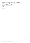
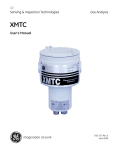
2 OPERATING PRINCIPLE
British Little Magic Thermodynamic Box works on the principle of thermodynamics. It’s the process of
heating water in a cylinder by using a refrigerant liquid which is circulated in an external panel
(evaporator) that absorbs energy from the ambient air. This energy excites the liquid which turns it into a
gas. This gas is compressed to create heat which is transferred to the water via the heat exchanger. Due
to the uniqueness of the direct gas evaporation principle the external thermodynamic collector can
absorb more heat during the day and night in all climates (rain, cloud, sun and wind).
Thermodynamic
Panel
British Made Little Magic
Thermodynamic Box
Water In
Domestic Hot Water Out
Gas out
Water
Cylinder
Liquid In
Temperature
Probe
Isolating Valve
Water Out
Mains Water Supply In
Water In
Water Out
Little Magic Thermodynamic Box Operating Principle Schematic
Installation instructions and user manual V1.1
5
3 TECHNICAL SPECIFICATIONS
TECHNICAL SPECIFICATIONS
Mean thermal capacity (only thermodynamic) (W)
840W to 2200W
Min to Max Mean power consumed (thermodynamic)
(W)
400W to 880W
Voltage / frequency
220-240V, 50Hz
Atmospheric temperature range (ºC)
-10°C to 35°C
Refrigerant fluid and charge
R134a, 0.70kg
Max. Hot water temperature (ºC)
55 ºC
Unit Dimensions (height x width x depth) (mm)
310mm x 420mm x 345mm
Packaging dimensions (height x width x depth)
410mm x 511mm x 442mm
Thermodynamic box weight (kg)
31 kg
Maximum water circuit working pressure (bar)
8bar
Cold water input connections (") /Hot water output
connections (")
¾” & ¾”
Thermodynamic panel weight (kg)
6.2kg
Thermodynamic Panel Dimensions
(height x width x depth) mm
Thermodynamic panel input/ output connections
(thread) SAE(”)
Thermodynamic unit input/ output connections (thread)
SAE(”)
Installation instructions and user manual V1.1
1700mm x 800mm x 25mm
¼” & 3/8”
3/8” & ¼”
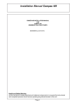
6
Fig. 1 INTERNAL LAYOUT OF LITTLE MAGIC THERMODYNAMIC BOX
Installation instructions and user manual V1.1
7
4 INSTALLATION
In the UK F-gas qualification is required to install and connect the panel to the Little Magic
Thermodynamic Box. The plumbing work has to be carried out by a plumber who is qualified to Level 3.
Outside the UK the installation needs to be carried out in accordance with the country’s local regulations.
Installation Steps:
1.
2.
3.
4.
5.
6.
7.
8.
9.
10.
11.
4.1
Install the Little Magic Thermodynamic Box
Install the Thermodynamic Panel
Refrigeration connections
Hydraulic connections
Temperature Sensor
Electrical connections
Pressure test during the installation with nitrogen, maximum of 10 bar.
Vacuum test during installation
Filling of the refrigerant circuit
Draining & bleeding of the hydraulic circuit
Turning the system on
Installing the Little Magic Thermodynamic Box
Siting location
Make sure there is enough clearance for the refrigeration pipes, hydraulic connections and
electrical wiring.
Make sure the fixing points and fixing methods will take the weight of the Little Magic
Thermodynamic Box. Please refer the Fig.2 for the fixing location of the unit.
The Little Magic Thermodynamic Box must be installed in horizontal position.
The equipment shall not be installed in a place where it exposed to corrosive gases, major
electrical fluctuations, high electromagnetic field, inflammable materials or other hazardous
areas.
We recommend a minimum pipe diameter of 22mm should be used in the hydraulic system
between Little Magic Thermodynamic Box and water cylinder.
Handling the unit
The unit must be transported and moved in the horizontal position and should never be turned over.
Should this happen then we recommend to leave the unit in the horizontal position for 24 hours before
commissioning.
Before handling the unit, check its weight (Section 3 “Technical Specification” of this manual).
During handling care should be taken to ensure it shall not be subjected to sudden movements or impact
in order to avoid damage.
Installation instructions and user manual V1.1
8
Installation of the unit
Step 1: Carefully remove the outer casing of the unit to gain access to the wall fixing points.
Step 2: Fix the unit to a suitable solid wall with four screws. We recommend the use of anti-vibration
mounts to minimize any possible vibration noise. (Please section 8)
Note: If the units is installed on the stud wall anti-vibration mounts must be used. Ideally we recommend
the use of anti-vibration mounts in every installation.
For maximum efficiency the Thermodynamic Box should be installed as close to the cylinder as possible
Fig.2 Positions of fixing holes. M6 or equivalent fixings are recommended
Sanitary hot water outlet is always recommended to be above the water feeding to the Magic Box
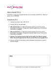
4.2
INSTALLING THE THERMODYNAMIC PANEL
We recommend to install the panel on the wall If the panel is installed on a roof it should be fixed
in accordance with MCS12. Compliance is the responsibility of the installer.
Fix the evaporator panel in a vertical (portrait) position (horizontal position it is also valid) with
the inlet pipes situated on the lower part as per the figure 4.
NOTE: Care must be taken to avoid bending the panel and the refrigerant pipes
The system is pre-charged with refrigerant gas for 8m of pipe length between the Thermodynamic
Box and the Panel. The pipe length can be extended up to 15 metres however for every extra
metre length of pipe 50g of refrigerant gas should be added.
To Fix the panel use the supplied brackets, fixing screws or bolts. Please see the picture below
for fixing the panel on the wall.
Installation instructions and user manual V1.1
9
It’s recommended to install the panel facing SOUTH, SOUTHWEST or SOUTHEAST for higher
performance. Installing the panel other than this location will have reduced performance. The
difference only contributes in daytime performance.
For increased performance, the panel can be installed parallel to the prevailing wind , allowing
the air to pass freely over the surface of the panel.
NOTE: If installed on the roof or similar then snow loads for the area should not exceed 1.0N/m2
and should not be exposed to wind velocities greater than 28m/s.
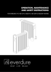
Connection of the panel: Gas outlet (fig. 3) is connected to the gas inlet of the unit (LMTB) and
liquid inlet (fig. 3) is connected to the liquid outlet of the unit (LMTB).
Fig. 3 Thermodynamic panel
Installation instructions and user manual V1.1
10
RIGHT
WRONG
Fig 4 Correct and incorrect placing of the panel
4.3
REFRIGERATION CONNECTIONS
BRAZING: The brazing shall be carried out by qualified F-gas engineers and in accordance with the
current local regulation. Any damage caused by an incorrect welding procedure will invalidate any
warranty.
The installation must be carried out by an F Gas (Or Country of installation equivalent) certified installer.
REFRIGERATION CONNECTIONS
NOTE: PIPEWORK SHOULD BE COMPLETED IN ACCORDANCE WITH EN378. COMPLIANCE IS THE
RESPONSIBILITY OF THE INSTALLER.
Refrigeration quality copper pipes must be used to connect the thermodynamic panel and the Little Magic
Thermodynamic Box.
This piping must be properly insulated with flexible anti-condensation insulation.
Direct contact between the refrigeration outlet and refrigeration inlet line shall be avoided to prevent
energy losses in the system.
Before brazing the piping, the system should be checked to ensure it is free of humidity and particles.
Installation instructions and user manual V1.1
11
The gas piping shall be designed with as few bends as possible to minimize the load loss and it shall be
supported properly with a view not to transmit stresses or vibrations.
Please check for leaks before insulating the pipes.
Fig 5. Refrigeration connections.
Note: Vertical panel position is
recommended for better even
distribution of the refrigerant.
Fig 6: Refrigeration connection between panels, Vertical and Horizontal
Both pipe ends connecting between the panel and the magic box need flaring. The suction pipe end need
flaring to ⅜”. The discharge pipe end need flaring to ¼”.
Installation instructions and user manual V1.1
12
Guidance value
Outside Temp. Vs Low side pressure
Water Temp. Vs High side pressure
Outside
Low Side
Temp (ºC)
Pressure (bar)
Water
Temp (ºC)
High Side
Pressure (bar)
-10
0.4
20
6.5
-5
0.7
25
7.1
0
1.0
30
8.1
5
1.4
35
9.2
10
2.0
40
10.5
15
2.6
45
12.0
20
3.2
50
14.1
25
3.9
55
15.6
30
4.5
35
5.1
4.4
HYDRAULIC CONNECTIONS
The Little Magic Thermodynamic Box has a water inlet and outlet located on the bottom front of the Box
(Please refer the fig 1). The minimum pipe size of 22mm should be used for the water connections.
Water inlet and outlet connections of the cylinder should be connected as per the fig 9 and 10.
Water inlet connection to the Little Magic Thermodynamic Box should always be connected to
the first tapping point of the cylinder. (refer fig. 9 or 10)
The installer should assemble the proper filter, pressure gauge, expansion vessel and safety
devices according to the scheme showed in fig 9 and 10.
Drain Cock must be installed on the lowest part of the system for the draining purpose.
A non-return valve must be installed. In a vented system ensure that the water pressure is sufficient to
open the valve otherwise air may be sucked into the system. In these circumstances a flap style valve
may be suitable.
The hydraulic system will vary dependant on the existing type of cylinder/buffer tank.
NOTE: Do not fit the pipes to an existing coil in the cylinder; this will stop the Magic Box reaching
maximum temperature.
Vented system: We highly recommended installing the surrey flange in the domestic hot water cylinder.
Unvented system: If you installing the Little Magic Thermodynamic Box in a unvented system please
make sure that the Temperature-Pressure release value is fitted to avoid over heating the cylinder.
Installation instructions and user manual V1.1
13
Fig. 9 Schematic of Unvented System
Installation instructions and user manual V1.1
14
Fig. 10 Schematic of Vented System
Installation instructions and user manual V1.1
15
4.5
TEMPERATURE SENSOR
Attach the supplied temperature sensor to the cylinder / accumulator tank. It is recommended to place it on the
middle of the cylinder. The wire can be extended on installation if required.
NOTE: Please ensure that good contact has been made between the temperature probe and surface of the
cylinder. Poor contact will result in incorrect temperature reading.
4.6
ELECTRICAL CONNECTIONS
The equipment shall be connected to the electrical system once all the refrigerant connections and hydraulic
connections are completed. Pay particular attention to ensure piping is bonded.
All electrical work is to be carried out in accordance with I.E.E standards, latest issue or local codes of practice
as applicable.
The equipment should be installed in line with EMC2004/108/EC
The power supply is single phase: 230V / 50Hz with earth connection. This supply needs to be separately
isolated, and protected by an appropriately sized fuse. (Maximum 13Amps)
The electrical schematic of the equipment is shown in the following figure:
Fig. 11 WIRING DIAGRAM
Installation instructions and user manual V1.1
16
4.7 PRESSURE TEST WITH NITROGEN
After the refrigeration connection has been made between the panel and the unit (LMTB) the piping needs to be
pressure tested to check for leaks. This should to be done by introducing Nitrogen into the pipe work and the
panel through the service port.
Note: Please make sure the pressure does not exceed 10 Bar in the panel and the pipe work
Check the welds with soapy water for leaks.
4.8 VACUUM TEST
Once the pressure test is completed and no leakage of gas has been confirmed the nitrogen can then be
removed. Connect the vacuum pump into the service port and start to vacuum the system. Hold the system in
vacuum for at least 40 minutes.
4.9 FILLING OF THE REFRIGERANT CIRCUIT
The Little Magic Thermodynamic Box comes with pre-charged refrigerant (R134a) of 700 grams which is enough
for the installation of up to 8m length between the panel and the main unit. Open the service ports to fill the
panel with refrigerant.
NOTE: For the installation involve more than 8m length of pipe run please contact Magic Thermodynamic Box
Ltd for the technical support.
NOTE: Once the refrigerant has been released please check the refrigeration connections with suitable gas leak
detector.
4.10 DRAINING & BLEEDING OF THE HYDRAULIC CIRCUIT
Once the installation is complete the water cylinder should be checked to ensure that it is full of water and free
from air.
Once the air has been bled from the main system please make sure to bleed the air from the Magic box. The
position of the bleed valve is shown below.
Also make sure to bleed the air from the pump which can be accessed on right hand side of the product.
Bleeding points
Installation instructions and user manual V1.1
17
4.11 TURNING THE SYSTEM ON
The Little Magic Thermodynamic Box may be started once the steps described previously have been completed.
To turn the Magic Thermodynamic Box ‘ON’, connect the product into the fused spur (please check section 8 for
recommended accessories) and turn the mains supply ‘ON’.
The Little Magic Thermodynamic Box digital control will light up showing the current temperature of the cylinder
and the pump will start to run. After 1 minute time delay the compressor will start to run. This time delay
function has been introduced to improve the efficiency and the life of the compressor.
Please leave the system running for 20-30 minutes and check the sight glass to make sure it is full of liquid.
Fully functioning system should show no bubbles.
Sight glass
Fig. 12 Control panel scheme
Installation instructions and user manual V1.1
18
5
DIGITAL CONTROLLER SETTING
TEMPERATURE ADJUSTMENT
The digital thermostat displays the temperature of the water at any time.
This thermostat is preset at 55ºC.
To view the set point temperature of the compressor, press the P button. To modify the adjustment
temperature leave the p button pressed for 7 seconds, SP be displayed. Using the buttons with the
arrow pointing upwards / downwards we can increase / reduce the set point temperature. Once set,
press the “P” button again. The temperature range is from 20 to 55ºC.To cancel the change leave the
display alone and the setting will return without any changes being made.
The unit will raise the temperature to 55°and then switch off. It will automatically start again to raise the water
temperature once it falls to 50°C.
WARNING: The programmed temperature for the unit should not ever exceed 55ºC
Fig.13 Digital thermostat scheme
OPERATING:
ACTION
DESCRIPTION
SET BUTTON
Keep pressed down for 7 seconds to change
the operating temperature of the compressor
COMMENTS
The temperature of the compressor
is pre-set at 55 ° C
Never exceed 55°C.
UP BUTTON
Increases the temperature
DOWN BUTTON
Decreases the temperature
Once the temperature is set; press the P key again
To modify the temperature follow the instructions in diagram 14.
Installation instructions and user manual V1.1
19
Fig. 14 Operating the digital thermostat
Installation instructions and user manual V1.1
20
6
REPAIR AND MAINTENANCE
WARNING: Follow the general warnings and safety rules listed at the section 1 of this manual. All maintenance
operations and interventions should be carried must by qualified F-gas engineers.
Maintenance
If the unit found to be very dirty it can be cleaned with water and non-abrasive detergent.
Note: When cleaning please ensure that the main electrical supply us turned off to the LMTB and don’t clean the panel if in direct sunlight.
The system should be drained off if the LMTB is out of use for a prolonged time period and the
electrical supply to the unit should be isolated.
Repair
Any repair work must be carried out by authorized installers or qualified engineers.
Periodic inspections of the descaler should be made to ensure the cleanliness of the system.
Installation instructions and user manual V1.1
21
7
TROUBLESHOOTING
Problems
Causes
The screen doesn’t show
Lack of power
any information
The system starts and
stops, the screen
switches off. A Dot
appears on the screen
(when off).
Solutions
Check the power supply
Check that the power switch is on
Incorrect gas load
Please check the gas through the sight glass
Air in the hydraulic circuit
Verify the cleanness of the hydraulic circuit
Check the pressure switches function properly
High Pressure switch is on
Lime deposits inside the hydraulic circuit: Change the filter
of the hydraulic circuit and clean the whole system
Check the functioning of the water pump and bleed the
pump.
Check the R134a load (check the sight for the refrigerant)
Non condensable gases in the
refrigeration circuit
E1 error appears on
screen
A dot appears on the
screen (nothing else)
Temperature probe
Check the continuity of the probe using a multimeter
Check the temperature probe connection
Low pressure or High Pressure
fault
Gas leak: Check for leaks in the refrigerating circuit
Check water pump for air and drain accordingly
Lower set temperature.
Check the temperature set point on screen
The temperature sensor is
disconnected to the cylinder
Check the right placement of the temperature sensor
inside the cylinder
The water is cold and the
The pipework between the panel
compressor is working
and the magic box is not properly
insulated.
Incorrect gas load
The panel is frosting
Empty the refrigeration circuit
Check the proper insulation of the hydraulic circuit and the
cylinder
Check the R134a load (check the sight for the refrigerant)
Frost could appear during the normal operation and it melts once the LMTB stops.
Air Lock
Please check the air in the system & bleed if required
Incorrect gas load
Check the R134a load (check the sight for the refrigerant)
The water does not reach
Incorrect Installation
temperature
Refrigerant Leak or Load
Installation instructions and user manual V1.1
Ensure panel is installed and unit installed correctly.
Check for leaks. If pipe run over 8 metres extra refrigerant
must be added (check the sight for the refrigerant)
22
8. MANUFACTURER RECOMMENDED ACCESSORIES
Anti-Vibration Mount
Inline Y-Filter
Non-Return Valve
Heat Transfer paste
Fused spur
9 GENERAL CONDITIONS OF WARRANTY
WARRANTY TERMS AND CONDITIONS
The product must be installed and commissioned in line with the manufacturers recommendations as set out in the
installation manual. The warranty must be activated within 30 days of commissioning. Magic Thermodynamic Box
Ltd will not be able to provide free assistance under these terms if you do not activate your guarantee within 30
days of installation. This does not affect your statutory rights. The Warranty Registration Form should be
completed by the installation engineer and returned to the address below or the Registration Form completed on
the website: www.magicthermodynamicbox.com
The installer/sales company should always be the end-users first point of contact, in the event of a breakdown or
other malfunction of the product. Only if/when confirmed that there is a fault with the Product and not with the
installation design or operation, then contact should be made with Magic Thermodynamic Box Ltd.
By this warranty, MAGIC THERMODYNAMIC BOX LTD, registered at 44/54 Orsett Road, Grays, Essex RM17 5ED,
Company No. 08309394, guarantees that this product is free from defects in materials and workmanship from the
date of purchase by the buyer from MAGIC THERMODYNAMIC BOX LTD, regardless of its final date of installation
and/or start-up, for the period of 60 months.
Installation instructions and user manual V1.1
23
The Warranty shall only be valid within European territory and subject to the following conditions:
Its installation shall be carried out in accordance with the manufacturer’s instructions and in compliance with all the
technical and safety standards applicable whether they are European, national or autonomous; it shall also be
undertaken by qualified staff.
The Warranty shall be null and void if any of the following takes place:
Incorrect equipment is used for installation
The equipment has been installed by staff other than an F Gas qualified engineer.
The equipment has been used for purposes other than those described in the use and deployment standards or in
some way other than that recommended in the mentioned standards.
The usage and maintenance instructions have not been complied with.
• Water supply for the unit that meets some of the following criteria: Chlorides content > 0.2ppm, pH value<6 (scale
Sorensen a 25ºC), CaCO3 content >200 ppm. In general water with values exceeding ceilings set by legislation.
• Absence of security group in the inlet system according to the legislation.
• System malfunction arising from improper installation of the hydraulic circuit components and/or buffer tank
• Installation of elements outside the specifications of the installation manual.
• Damage resulting from improper anchoring equipment.
• Unit malfunction due to lack of thermal insulation in the installation
Incorrect placement of thermodynamic solar panel or box
The equipment has received an overload of any nature: electrical, water pressure etc.
Malfunctions brought about by chance or force majored: atmospheric, geological phenomena etc.
The equipment has not been delivered in its original box.
Damage from atmospheric and external agents: Freezing, dirt, transport, or accidental impacts.
Damages derived from an unusual supply of electricity, water or air ( included over pressure and over voltage)
Damage caused by daily wear in metal or plastic.
Breakdowns caused by the replacement of parts or elements not original or authorized in writing by the
manufacturer
Damages occasioned by the unusual corrosion of the heat exchanger and/or the hydraulic circuit caused from
reaction with the circulating fluid.
Damages derived from the installation itself.
Damaged occasioned by vandalism acts, war, fire, etc.
The present warranty does not have effect if the general conditions of sale have not been met between the supplier
and the domestic end user for the specified equipment, or if the agreed payment terms have not been respected.
The end user or customer does not have any right to make any claim for compensation during the time the
equipment is damaged or under repair or for damages caused directly or indirectly.
IN ORDER THAT THE WARRANTY TAKES EFFECT, IT IS ESSENTIAL THAT THE WARRANTY APPLICATION FORM IS
COMPLETED AND RETURNED TO THE MAGIC THERMODYNAMIC BOX LTD WITHIN 30 DAYS OF INSTALLATION OR
THE INSTALLATION IS REGISTERED ONLINE AT: WWW.MAGICTHERMODYNAMICBOX.COM
TO REGISTER YOUR WARRANTY SIMPLY COMPLETE THE ATTACHED APPLICATION AND SEND
IT WITH A PHOTOCOPY OF THE INVOICE BY POST TO THE ADDRESS
MAGIC THERMODYNAMIC BOX LTD
115, New London Road, Chelmsford, CM2 0QT
Tel: 08449671500 email: [email protected] www.magicthermodynamicbox.com
Installation instructions and user manual V1.1
24