1
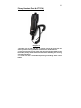
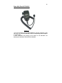
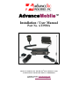
AdvanceMobile™
Installation / User Manual
Part No. AT3550A
AdvanceTec Industries, Inc 1150 NW 163rd Drive, Miami, FL 33169
T: 305-623-3939 F: 305-623-3996 Toll Free: 1-800-881-8211
Company web site: www.advancetec.com
GPS services: www.advancemobilegps.com
2
3
Index
Page
Description
3
Part numbers and installation guides
3-4
Installation Warnings
4 -5
Installation of Speaker
5-6
Installation of PTT
6
Installation of Microphone
6-8
Installation of Power Cable
8 - 10
Installation of Vehicular and GPS
Antenna
10
Installation of Emergency PTT
10 - 11
Inserting SIM into Junction Box
11 - 12
Connecting Cables to Junction Box
12 - 13
System Registration and Programming
14
Making and receiving PTT call
14
Receiving incoming Cellular call
14
Turning AdvanceMobile™ OFF
Optional Extra Accessories
15 - 17
AdvanceMobile Control Modules
18
Privacy Handset with Cradle
19
Palm Mic.
Specifications
20 - 22
Specifications
4
The AdvanceTec AdvanceMobile™ is designed to provide secure and
convenient vehicular communication with GPS tracking if needed.
The AdvanceMobile™ consists of:
1. Part # AT8246A
Junction Box
2. Part # AT8231A
Speaker
3. Part # AT8230A
Visor Microphone (Visor Mic.)
4. Part # AT8232A
Power cable
5. Part # AT9299B
Push-To-Talk (PTT)
6. Part # AT8407A
Antenna Magnet Mount (Mag. Mount)
Optional Extras
1. Part # AT8410A
2. Part #AT7107A
3. Part #AT9298A
4. Part # ATAT8408A
5. Part # AT3510A
Palm Microphone
Privacy Handset with cradle
RED Emergency PTT
Antenna GPS
AdvanceMobile Control Module
! Note
A properly installed AdvanceMobile™ will minimize service calls and equipment downtime. Because of the wide variations in vehicle design, these
instructions should be modified to suit each particular installation.
Before beginning the installation process, determine the locations for the
mounting of the PTT, Visor Microphone, Speaker and Junction Box, and
Magnetic Mount Antenna.
Consider the following guidelines when planning the installation:
•
DO use all mounting hardware provided.
•
DO ensure that cables are not placed under stress.
•
DO follow proper + and - connections.
•
DO crimp connectors securely.
•
DO NOT attach components to any part of the vehicle that is not rigid
or is subject to excessive vibration.
•
DO NOT install components in areas where rain or snow can easily get
into them, such as next to a vehicle window, which may be left open.
•
DO NOT dress cables over sharp edges that could cause wear or
tearing of cable insulation.
•
DO NOT install components in locations where they might interfere
with the vehicle operator or operating controls.
•
DO NOT install the PTT where it will be difficult for the operator to
reach.
VEHICLES EQUIPPED WITH AIR BAGS
An air bag inflates with great force. DO NOT place objects, including
communications equipment, in the area over the air bag or in the air bag
deployment area. If the communication equipment is improperly installed and
the air bag inflates, this could cause serious injury.
5
It is recommended that the installation of the vehicle communication equipment
be performed by a professional installer/technician trained in the requirements
for such installations. An air bag's size, shape and deployment area can vary by
vehicle make, model, and front compartment configuration (for example, bench
seat vs. bucket seats). Contact the vehicle manufacturer's corporate
headquarters, if necessary, for specific air bag information for the vehicle make,
model, and front compartment configuration involved in your communication
equipment installation.
! WARNING
VEHICLES WITH ANTI-SKID BRAKING SYSTEMS
For vehicles with electronic anti-skid braking systems, refer to the "Anti-Skid
Braking Precautions," Motorola publication 68P81109E34. This publication
can be ordered from Motorola® Worldwide Systems and Aftermarket Parts
Department.
Operating the AdvanceMobile™
The AdvanceMobile™ will allow:
1. PTT calls from the unit to a pre-set private ID or group ID.
2. PTT and Cellular calls to the unit.
3. When used with the Optional Control Module, PTT calls from the unit to a
Group ID and 9 different Private ID numbers.
Set up of AdvanceMobile™
NOTE! The AdvanceMobile™ requires an iDEN SIM card. To acquire
such a SIM card, contact your local iDEN Provider sales
representative or retail store.
Installation of AdvanceMobile™
A. Speaker Installation
1. Mount the Speaker beneath the dashboard, on the passenger's side of the
vehicle, out of the way of the passenger. Do not mount the Speaker on the
dashboard or the rear window shelf.
2. The Speaker should be located more than four feet from the junction box.
3. The Speaker includes a mounting bracket, permitting it to be mounted in a
variety of ways. Loosen the thumbscrews on the side of the speaker and
using the mounting bracket as a template, drill the necessary mounting holes
and secure the bracket with the self-tapping screws provided.
6
Mounting Bracket
Thumb Screws
Diagram 1
4. Position the Speaker on the mounting bracket and secure it by tightening
the thumbscrews. The mounting bracket is used to permanently mount the
Speaker in place while permitting it to be tilted to a desired angle.
5. Feed the cable out of sight to the location where you intend to mount the
junction box.
6. The speaker should be located at least 3 ft (1m) from the visor mic. Avoid
placing the speaker where it faces the visor microphone.
B. Mounting of the PTT
1. To attach the PTT to the gear lever, strap the PTT around the gear lever
using the Velcro strip attached, with the cord facing down.
Velcro Strip
Flat Plastic
Diagram 2
7
2. To attach the PTT to a flat surface, remove the 2 screws from the bottom of
the PTT, which holds the Velcro strip in place. Remove the strips and replace
the small plastic part that held the strips in place with the larger flat plastic
part supplied with the PTT. Screw the new plastic part in place.
3. Feed the cable out of sight to the location where you intend to mount the
junction box.
Caution: Make sure there is sufficient slack in the cable to allow the free
movement of the gear lever without stretching the PTT cable.
C. Mounting the Microphone
Selecting the correct position for the microphone is vital for the successful
performance of the AdvanceMobile™
1. The Microphone should be mounted either on the sun visor directly above,
and facing, the driver or on the headliner just above, and facing, the driver.
One of the following two microphones will be supplied with this kit.
Facing the driver
Diagram 3
2. The microphone supplied has a noise canceling feature so must be
mounted facing the driver as shown in the picture above.
3. To avoid visual or physical obstruction, route the microphone cable down
inside the door molding. Allow sufficient slack in the connector end of the
cable to reach the Junction Box.
4. Feed the cable to the location where you intend to mount the junction box.
Note: The microphone should not be mounted near a window or in a spot
where road and ambient background noise would be substantially high
(above 85dB SPL).
D. Installing the Power Cable
8
Caution: The AdvanceMobile™ should be used with a negative ground
electrical system only. Reverse polarity (positive ground) will trigger
protection circuits which cause the cable fuse to open. Check the ground
polarity before you begin the installation to prevent wasted time and effort.
12V DC or 24V DC automotive systems are directly supported
Determine the best cable route to the vehicle ignition for the Power Cable
from the location where you intend to mount the Junction Box.
Diagram 4
1. The DC power cable shipped with the AdvanceMobile™ is suitable for
installation in most vehicles.
2. Route the black lead of the main power cable to a convenient chassis
ground and the red lead to the positive supply voltage connection points. If it
is necessary to penetrate the firewall, try to use an existing opening.
3. If there is no existing opening, drill a new hole approximately 9/16” or
3.5cm in diameter. Make sure that there is enough clearance on the opposite
side. Insert a grommet into the hole to prevent damage to the power cable.
When making connections on the engine side of the firewall, additional in-line
fuse holder (included) should be used at the connection points.
Diagram 5
9
4. Cut the black lead to the desired length.
5. If the connection is being made under the dash or in the vehicle cabin,
connect the black lead directly to the chassis of the vehicle.
6. If the connection is being made in the engine compartment, connect the
in-line fuse holder between the black lead of the power cable and the desired
chassis connection point.
Note! Do not connect the black lead to the negative (-) battery terminal.
The AdvanceMobile™ could be damaged if there were a malfunction in the
vehicle’s electrical system.
7. Cut the red lead to the desired length. This lead will be connected such
that it has positive supply voltage at all times, even when the vehicle is
turned off.
8. If the connection is being made under the dash or in the vehicle cabin,
connect the red lead to a positive supply voltage point.
9. If the connection is being made in the engine compartment or directly to
the battery, connect the in-line fuse holder between the red
lead of the power cable and the desired positive voltage connection point.
10. Route and connect the green lead to a convenient ignition switch supply
point in the vehicle.
Note! An ignition switch accessory terminal can be verified by measuring
the terminal while operating the vehicle’s key switch. With the ignition key in
the “accessory ON” position, the terminal voltage should measure the
vehicle’s battery voltage. With the switch in the “OFF” position, it should
measure near zero
Stereo Mute
If the vehicle’s stereo system supports an external muting feature, route and
connects the orange wire to the car stereo system. Otherwise, the orange
wire may be left unconnected and cut off or tied out of the way.
Note! The Car Kit supports an “Entertainment Mute” function when
connected to a car stereo system that provides for external muting. This
function is compatible with systems that mute the audio output when the
control line is connected to ground
E. Mount the Vehicular Antenna & GPS Antenna
1. Screw the antenna to the external magnetic (Mag) mount antenna base.
2. Mount the Mag Mount antenna or other external vehicular antenna (to be
purchased separately if the supplied Mag Mount Antenna does not fit your
purposes).
For best performance use a low-loss coaxial cable with the highest gain
antenna.
10
3. Position the antenna, maintaining a separation distance of at least 8 inches
(20 cms) between the antenna and the body of any user and
nearby person, to assure compliance with the U. S. FCC regulations on RF
exposure.
GPS Antenna
External Antenna
Diagram 6
4 Connect the antenna cable to the external antenna connector on the
junction box.
GPS
Antenna
USB
Emergency
Data Output
PTT
External
Antennas
Diagram 7
5. If you intend to make use of the GPS feature, connect the GPS antenna
cable to the GPS antenna connector on the junction box. The GPS antenna is
an optional extra that is available to be purchased from AdvanceTec.
6. Feed the antenna cables out of sight to the location where you intend to
mount the junction box.
11
F. Emergency PTT
The RED Emergency PTT is available as an optional extra
1. To attach the Emergency PTT to the gear lever, strap the PTT around the
gear lever using the Velcro strip attached, with the cord facing down.
Velcro Strip
Flat Plastic
Diagram 8
2. To attach the Emergency PTT to a flat surface, remove the 2 screws from
the bottom of the PTT, which holds the Velcro strip in place. Remove the
strips and replace the small plastic part that held the strips in place with the
larger flat plastic part supplied with the PTT. Screw the new plastic part in
place.
3. Feed the cable out of sight to the location where you intend to mount the 4
pin connector on the junction box.
Caution: Make sure there is sufficient slack in the cable to allow the free
movement of the gear lever without stretching the PTT cable.
Inserting SIM into Junction Box
1. Open the SIM door cover on the bottom of the junction box by removing
the screw holding it shut
Screw
Diagram 9
2. Slide the metal SIM cover to the left and lift the cover.
12
Diagram 10
3. Insert the SIM card under the metal cover and close the metal cover and
slide to the right to lock.
Diagram 11
4. Replace the plastic SIM cover and screw it closed.
NOTE: The SIM card can not be inserted or removed while the Junction Box
is powered. To remove or replace the SIM card after installation has been
completed, the power cable must be disconnected from the Junction Box
Connecting cables to Junction Box.
1. Locate a position for the junction box beneath the dashboard on the passenger's side of the vehicle or on the center side post between the
front seats. It must be protected from dirt and moisture and must be afforded
adequate space for cooling. There must be sufficient space to allow for
connection of all cabling.
13
2. DO NOT mount the junction box at this stage. Connect the PTT,
Microphone, Speaker, Power cable and to their corresponding connections
on the Junction Box as indicated in Diagram below.
Mic.
Speaker PTT
Optional
Optional
Power
Control Module Palm Mic/.
Handset w/Cradle
Diagram 8
3. Connect the coaxial antenna cable to the corresponding connector on the
opposite side of the Junction Box.
4. After connecting the power cable's connector to the Junction Box,
cut in half the red wire attached to the fuse housing supplied. Cut the long
red power lead to the desired length and connect (crimp) it to the one end of
the wire to the fuse housing.
5. Connect the other end of the wire from the red fuse housing to the positive
(+) side of the ignition. The fuse housing can be secured in place by using a
plastic tie or screw through the hole in the fuse's plastic housing
System Registration and Programming
1. Once the AdvanceMobile™ is powered and the SIM is inserted, it will begin
the registration process onto the iDEN system. The initial registration onto
the iDEN system can take up to 3 minutes.
2. Once the AdvanceMobile™ has successfully registered onto the iDEN
system, 5 short pulses will be heard through the speaker.
3. After registration, the Private ID or Group ID with which the
AdvanceMobile™ will communicate must be loaded
into
the
AdvanceMobile™
4. To program the Private ID or Group ID, initiate a PTT call to the
AdvanceMobile™ from the phone with the Private ID or a phone that is part of
a Group ID with which you want the AdvanceMobile™ to communicate. Keep
the PTT button pressed
5. When the incoming PTT call is heard on the AdvanceMobile™ speaker,
with the PTT button still pressed, press in the programming button next to
the SIM flap by using a pen refill or similar devise.
14
Programming button must be
NOTE! Both the PTT and the
kept depressed until the programming has been successfully completed and
the 5 fast beeps are heard on the speaker.
Diagram 12
3. Once the Private ID or Group ID has been successfully loaded, proceed to
permanently mount the junction box with the screws provided ensuring that
all extra cabling is secured out of harms way.
Mounting holes
Mounting holes
Diagram 13
Making a PTT call to Private ID or Group ID programmed.
1. Press and hold down the PTT button.
2. Speak towards the visor microphone.
15
Incoming PTT
1. To respond to an incoming PTT call that is from the PTT Private ID or
Group programmed into the AdvanceMobile ™, press and hold down the PTT
button.
2. Speak towards the visor microphone
3. To respond to an incoming PTT call that is NOT from the Private ID or
Group programmed into the AdvanceMobile ™, press and hold down the PTT
button within 15 seconds of the receipt of the PTT call.
4. Speak towards the visor microphone.
Incoming Cellular call
1. To answer an incoming cellular call press and hold the PTT button for 3
seconds. Once the incoming call is answered, release the PTT to continue the
cellular conversation.
3. Speak towards the visor microphone.
4. To end the cellular call, press and hold down the PTT.
Turning AdvanceMobile™ OFF
1. When the car ignition is ON, the AdvanceMobile™ will stay on.
2. When the ignition is turned OFF and there is no active call or dispatch in
progress, the AdvanceMobile™ will turn OFF after 30 seconds.
3. The AdvanceMobile ™ will remain on if an active call or dispatch is in
progress even if the ignition is turned OFF>
16
Optional Extra Accessories
AdvanceMobile™ Control Module (Part # AT3510A)
The AdvanceMobile™ control module (Control Module) is an optional extra
which will enhance the features and functions of the AdvanceMobile™. With
the addition of the Control Module, PTT calls from the AdvanceMobile™ can
be increased from a single Private ID or Group ID to a Group ID and 9
different Private IDs.
Volume Control
Buttons
Channel Control
Buttons
Diagram 14
Program
1. Attach the connector at the end of the cable of the Control Module to the
corresponding connector on the AdvanceMobile™ junction box.
2. With the AdvanceMobile™ powered, press the UP or DOWN Channel
Control Button. Channel numbers from 1 to 9 will show in the Control Module
screen. (Channel number 0 will show “E” and is used for an Emergency
number)
3. A flashing number in the screen indicates that the channel is open (not
programmed) and available to be programmed.
4. With a channel number flashing, initiate a PTT call to the AdvanceMobile™
from the phone with a Private ID that you want the AdvanceMobile™ to
communicate. Keep the PTT button pressed
5. When the incoming PTT call is heard on the AdvanceMobile™ speaker,
with the PTT button still pressed, press in the programming button next to
the SIM flap by using a pen refill or similar devise.
17
Diagram 15
NOTE! Both the PTT and the Programming button must be kept depressed
until the programming has been successfully completed and the 5 fast beeps
are heard on the speaker.
5. Once the new private ID is successfully programmed, the channel number
in the screen will no longer flash.
6. This process can be repeated with the other open channels until each of
the 9 channels are programmed with different private IDs
Operation
1. Select a channel by pressing the Left Channel Keys Up and Down.
If the Display shows a steady number (1-9), the channel displayed is the
channel selected and programmed. When the PTT is pressed, it will transmit
on that channel.
2. If the Display shows a slow flashing number (1-9), the channel is not
programmed. If the PTT is pressed, a reject tone will be heard.
3. If the Display shows a fast flashing number (1-9), a call is coming in from
the remote user who is programmed into the AdvanceMobile™ on that
channel number. Press the PTT to answer the incoming caller.
4. If the Display shows a fast flashing “U” a call is coming in from an
unknown remote user who is not programmed into the AdvanceMobile. Press
the PTT to answer the incoming caller.
5. If the Display shows fast flashing “E” a call is coming in from a remote
user programmed as an Emergency number.
18
6. Adjust the volume by pressing the Right Volume Buttons Up or Down.
After a volume button is pressed a blinking dot will appear in the bottom right
corner of the screen to indicate that it is in the volume mode. The Minimum
volume is 0 and the Maximum is 5.
After the volume has been adjusted, the blinking dot will disappear to
indicate that the unit is back in the channel mode.
7. The Channel and Volume selected will be saved when the Control Module
is powered off and will resume when it is next powered up.
8. If the Control Module looses communication with the main unit, it will
show 3 horizontal lines.
LED indicators:
Flashing red
Unit not yet registered
Steady Green
Unit registered - OK
Blinking Green
Unit registered OK and Ignition is off.
The Unit is about to shut off.
Steady Green & Red (Amber)
PTT is in operation
Alternating Green & Red
Data is transmitting for GPS.
19
Privacy Handset ( Part # AT7107A)
Diagram 16
1. PTT calls can be made and PTT and cellular calls can be received in the
same way with the Privacy Handset as with the PTT described above.
2. Lift the privacy handset out of the cradle and using the PTT button on the
back of the privacy handset follow the instructions for making and receiving
calls as set out above.
3. A cellular call can be terminated by pressing and holding down the PTT
button.
20
Palm Mic (Part # AT8410A)
Diagram 17
1. To use a Palm Mic. with the AdvanceMobile™, plug the connector on the
end of the coil cord of the Palm Mic. into the corresponding RJ45 receptacle
on Junction Box.
2. Once connected, the pressing of the switch on the Palm Mic. will
deactivate the Visor Mic. and activate the Palm Mic.
21
Specifications
Input/Output
•
•
•
•
•
•
Input voltage 10.5Vdc to 32V dc
Ignition detection:
Ignition “ON” 2.5Vdc to 32Vdc
Ignition “OFF” 0V to 2.5V or OPEN
Outputs Entertainment Mute
Open Drain
Continuous current capacity: 50Ma
Audio Specifications
•
•
•
•
RJ45 Supports, Palm MIC # AT8410A and Privacy Handset Part #
AT7107A
2.5mm Stereo audio jack
Speaker impedance: 4 Ohms 10W
Microphone: Eco Canceling Noise Canceling
Communication Specifications
•
•
•
•
•
•
Full Duplex Communication
Automatic Start up
Antenna Impedance: 50 Ohms
SIM card: 3 Volts
SIM cars PIN: Programmed by user one time, automatically
introduced
Onward. PIN saved on Non-Volatile memory
Receiver Specifications
•
•
•
•
•
•
•
•
•
•
•
•
•
Frequency Range 851 min 870 MHz Max in the 800MHz band
Frequency Range 935 min 941 MHz max in the 900MHz band
Channel Spacing 25 N/A KHz
Sensitivity (10% BER) – 111dBm max
Strong Signal BER 0.1% max RF level = -80 dBm
Overload Immunity 10% max on channel =_20dBm
Intermodulation Immunity -45 dBm min Far-out interferers
(On cannel= -108dBm)
Adjacent Channel Immunity -51 dBm min
Spurious Response Immunity -51 dBm min
Stability, unlocked 5 ppm max
Stability, unlocked 1.9 ppm max
Spurious Emissions per FCC requirements (3m)
22
•
•
•
•
•
Conducted -57 dBm
Radiated 500 uV/m
Transient Response 0.01% BER during RX-TXRX
Frequency Acquisition 0.01% max ± 220 Hz RF input
Blocking Immunity 10% max
Transmitter Specifications
•
•
•
•
•
•
•
•
•
Frequency Range min 806 max 825 MHz band
Frequency Range min 896 max 900 MHz band
Channel spacing 25 KHz
Power 0.44W min 0.7W max. Pulse average power: basic
Terminal class
TX BER 0.7% max
ACCPR @ 25 KHz 60 dB min
Frequent Stability 5 ppm max Unblocked to base
Spurious Emissions – 13dBm max per FCC and IPU-R requirements
iDEN / GPS Specifications
GPS Module
•
•
•
Sensitivity : -152 dBm Tracking, -142 dBm Acquisition
Protocol: TAIP (ASCII)
Frequency: L1 type (1575.42 MHz) C/A code
•
•
Channels: 12 channel simultaneous operation
Update rate: 1Hz
Accuracy
•
•
•
•
Horizontal: <3 meters (50%). <8 meters (90%)
Altitude: <16 meters (50%), <16 meters (90%)
Velocity: 0.06 m/sec.
PPS” +/- 50 nanoseconds
Acquisition
•
•
•
•
Reacquisition: 2 sec.
Hot Start 9 sec.
Warm Start 35 sec.
Cold Start (TTFF): 39 sec. Out of the box: 41 sec
GPS Antenna Connection
•
SMA (Sub Miniature A) connection with a male center contact. Use
this contact for the GPS Antenna provided with the unit.
•
50 Ohms impedance
23
GPS Antenna Spec.
Patch
•
•
•
•
•
•
•
Center Frequency 1575.42 ± 1.023 MHz (when covered with a radome
and measured by LNA ground plane)
Bandwidth (10dB return loss) 10 MHz min
Gain at Zenith 1dB type
Gain ay 10° elevation -5 dBic type
Polarization R.H.C.P.
Axial Ratio 5.0 dB type
Filter / LNA
•
•
•
•
•
•
•
•
•
•
•
•
Center Frequency 1575.42 ± 1.023 MHz
Gain 30~37 dB (pc:3V/32dB)
Noise Figure 1.4 dB type (ps:3V / 1.35 dB)
Filer out band attenuation
Dielectric filter
7dB min
fo±20 MHz
20dB min
fo±50MHz
30dB Min
fo±100MHz
(fo=1575.42MHz)
Output V.S.W.R 2.0 max
Voltage DC = 2.5~5.5V
Current DC = 8~23mA (ps:3V / 10mA)
iDEN antenna connector
•
•
Mini USB connector with a female center contact (Use this connector
for the iDEN Antenna provided with the unit.
50 Ohms impedance
Environmental Specifications
•
Operational Temperature -20 to +60°C
•
Storage Temperature -40 to +85°C
•
Shock MIL-STD-810E METHOD 516.4 Proc. 1, 18 shocks 40 G halfsine 6 – 9 msec 18
•
Shocks 2500g’s, 0.00075-second pulse
•
Vibration 2X-EIA (not tested electronically during vibration) Sine 20 –
2000 Hz, 4G peak
•
1 hr per axis – 3 axis (X, y, z) Random 20 – 2000 Hz, 6G RMS; 1 hr per
axis – axis (x, y, z)
24
AdvanceMobile™
GPS services
www.advancemobilegps.com
AdvanceTec Industries, Inc 1150 NW 163rd Drive, Miami, FL 33169
Tel: 305-623-3939 Toll Free: 1-800-881-8211
www.advancetec.com