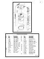
1
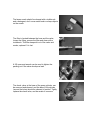
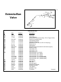
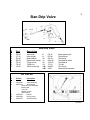
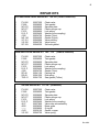
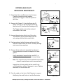
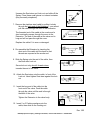
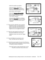
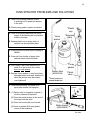
PROFESSIONAL SPRAYERS
USER’S MANUAL
Care and Maintenance
Safety Precautions
• Do not pressurize tank with external air or gas source; do not
pressurize above 50 psi.
• Do not adjust the tip or change spray patterns while depressing the valve trigger.
• Open tank cap slowly to release air before removing; keep
tank upright when releasing pressure.
• Do not store or transport the unit while tank is pressurized.
Before Starting
• Inspect the hose, tank gasket, discharge valves, and nozzle
for signs of wear or damage. These parts must be in full working condition to permit tank pressurization.
• It is recommended that compressed-air sprayers be used with
a pressure gauge (B&G #AG-3) or a pressure regulator (B&G
#460) fitted to the valve.
Operating Instructions
Filling and Mixing
• When mixing insecticides in the tank, first add about 1/2 the
water then the chemical, followed by the remainder of the
water required.
• Note gallon marks on the side of the tank and mix accordingly.
• Replace the pump and tank cap assembly, be sure the tank
gasket fits properly; tighten the cap until snug (do not over
tighten).
• Mix all insecticides according to label directions.
Pressurizing the Tank
• Disengage the handle from locked position by pressing down
and turning 1/4 turn to the left.
• Pump plunger up and down until desired pressure for application is achieved, then engage handle in the locked position.
Operation
B&G sprayers are designed for a variety of professional uses,
such as outdoor perimeter spraying, and indoor spraying, which
includes surface treatments and crack-and-crevice applications.
Application Rates*
50° coarse fan = 14.1 oz/min
80° fine fan = 6.4 oz/min
Pin stream = 8.9 oz/min (large)
4.5 oz/min (small)
*Calibrated at 20 psi
• Flush tank, valve, and extension with clean water regularly.
• Do not use bleach or ammonia-based cleaners, these will
damage the stainless steel and brass parts.
• After rinsing the tank with clean water, pressurize the tank
and flush the valve and hose.
• Inspect hoses and hose connections, gaskets, washers and
other fittings for wear; replace when necessary.
• Clean the filter at the hose/valve connection regularly.
• Do not use metal objects to clean the orifices in the nozzle,
this will disrupt the liquid spray pattern.
• Use the B&G Cleaning Kit (#22028000) for regular maintenance and cleaning of the sprayer.
Trouble Shooting
Problem: Tank not holding pressure
Solution: • Tighten tank cap
• Replace tank gasket (P-268)
Problem: Tank not getting air pressure
Solution: • Replace plunger cup (NPO-277)
• Replace or add oil to leather plunger cup
Problem: Pump cylinder filling with water when pumping
Solution: • Clean around the check valve at the bottom
of pump cylinder
• Replace the check valve (PV-266)
Problem: Holds pressure, but will not spray
Solution: • Nozzle clogged, clean with a soft brush
• Cracked siphon tube, replace
• Siphon tube clogged, clean end
• Clean strainer at the base of the valve, at the
hose / valve junction
Problem: Hose leaks at tank fitting
Solution: Replace hose washer (D-51-P)
Problem: Valve body leaking
Solution: • Extenda-Ban: Tighten packing nut, replace
packing washers (in D-124 Repair Kit)
• XR-Valve: Replace O-ring at base of handle;
replace copper gasket at base of valve stem
(in GT-100 Repair Kit)
• Ban-Drip: Tighten packing nut; replace rod
packing (RP-48)
Problem: Tip Leaking
Solution: • Extenda-Ban: Clean or replace soft seat gasket,
replace valve spring (in GD-124 Repair Kit)
• XR-Valve: Clean or replace check valve at end of
valve extension
• Ban-Drip: Clean or replace seat gasket; replace
rod spring (RS-49)
95138230 Rev 5/10
CARE AND MAINTENANCE OF YOUR B&G SPRAYER
The 1-gallon B&G sprayer is the workhorse of professional pest control. Most
service technicians use their sprayer every day for routine pest control service, or
for special jobs that require precise application. The tip shut-off (no drip) feature
ensures customer safety, and the rugged stainless steel and brass construction
ensures long service. However, like other pieces of equipment, the sprayer has
moving parts, valves, and washers that require regular maintenance to keep
them in top condition. Monthly care and maintenance of the sprayer will keep it
trouble-free.
A Six-Point Maintenance program can keep your B&G sprayer ready for any pest
control job. This program covers key components of the sprayer—from the spray
tip to the tank. It takes about 10 minutes, and requires only a 3/8 open-end
wrench, a long-handled plastic brush, and an old toothbrush. Start with an empty
tank and the hose drained of liquid. It helps to work at a sink with good lighting.
Start at the tip or nozzle and work back to the pump tube, and finish by cleaning
the tank.
Six-Point Maintenance
•
Nozzle – The brass nozzle determines the pattern (pin-stream or fan) of
the liquid spray. The nozzle is made of thick brass and will survive being
knocked around in the back of service trucks. However, with extended use
the openings for the fan sprays and the pin-stream will gradually enlarge.
This increase will change the angle (80 degrees for the fine fan, 50
degrees for the coarse fan) of the spray, and the distribution of the liquid in
the fan may become uneven.
The general appearance of the nozzle may not indicate that the openings have
enlarged or are damaged. Replacing the nozzle every 2 years is a reasonable
schedule, and will maintain an accurate spray pattern and flow rate.
•
Hose – The hose will give long and trouble-free service, and needs
replacement only when damaged. Check connection points: hose to valve,
and hose to tank. These are common sites to show wear and to develop
leaks. Leaks at fittings may require replacing the Teflon washer (D-51-P),
don’t over-tighten this fitting and damage this washer. If there are cracks
or swelling in the hose, replace it immediately.
•
Filter/Strainer –The small filter./strainer should be removed, cleaned, and
replaced regularly. Regardless of the water source or insecticides used,
small pieces of dirt and debris often get into the tank. The strainer keeps
dirt from clogging the valve, preventing tip shut-off, and blocking the spray.
A toothbrush can be used to clean the strainer.
•
Valve – The Extenda-Ban valve is designed for long service without
leaking. A leak in the gaskets may result in a small amount of liquid on the
handle, or at the end of the valve. Small leaks can be corrected by slight
tightening of the packing nut (use a 3/8 wrench).
•
Check Valve —The check valve at the base of the pump cylinder admits
air into the tank as the pump handle is depressed. It can become worn
and deposits around its edge (on the pump cylinder) can cause it to leak.
Replacing the check valve (PV-266) will keep the pump working and to
maintain proper tank pressure. Clean the bottom of the pump cylinder, a
small brush will remove deposits that build up around the edge of the
check valve.
Cleaning the Tank
Pesticide residues can form on the inside of the tank, especially when the tank is
not emptied every day. Cleaning inside the stainless steel tank is an important
part of a care and maintenance program, but should be performed carefully and
with the correct cleaning fluids and brushes.
Do not use bleach as a cleaning agent. It is not effective in removing pesticide
residue, and it can create small holes in the tank. Cleaning should be done with a
warm, ammonia-based detergent solution and with a plastic brush (toilet-bowl
brush works well) to remove residue from the tank bottom and sides. The siphon
tube extends along the side and close to the bottom of the tank; be careful not to
hit (and possibly bend) the siphon tube when using a brush to clean inside the
tank. The hose can be cleaned with detergent solution by pressurizing the tank
and spraying into the sink for several minutes. Rinse the tank with clear water
several times, and flush the hose with clear water. If the sprayer is not going to
be used for an extended period, remove the pump unit and store the tank upside
down.
The brass nozzle should be cleaned with a toothbrush
and a detergent; don’t use a metal brush or sharp objects
on the nozzle.
The filter is located between the hose and the valve;
loosen the fitting, remove the filter and clean with a
toothbrush. This filter keeps dirt out of the valve and
nozzle, replace if it is lost.
A 3/8 open-end wrench can be used to tighten the
packing nut if the valve develops a leak.
The check valve, at the base of the pump cylinder, can
be removed and cleaned, and the base of the cylinder
(around the holes) should be cleaned of residue. Tightly
replace the check valve, and be certain it is secure.
3
26
21
Extenda-Ban
Valve
24
28
36
30
35
20
31 32
34
37
38
39
42
40
43
44
45
41
Extenda-Ban Valve
#
Part
Order #
Description
20
21
VB-147
VT-140
22044450
22042800
24
26
28
PN-150-2
VP-151
AS-148
22042455
22045099
22044500
30
31
32
34
35
SL-162
NG-146
MS-145-50
SA-143
VC-152
VC-153
VC-163
VE-154
VE-155
VE-164
VE-154-SS
VE-155-SS
VE-164-SS
VS-156
SSL-157
SS-158
SP-159
5850-CC
9751-M
4190
5800-CC
4596
22046700
22044200
22043800
22043400
22045300
22045400
22045450
22045500
22045600
22045650
22045510
22045610
22045710
22045700
22045900
22046100
22046300
22049466
22034700
22034700
22049467
22034500
Valve body
Valve Trigger Kit
(includes SH-142 Screw housing, TS-141 Trigger screw)
Packing nut (stainless steel)
Valve packing washer
Adjustment Screw Kit
(includes LN-149 Lock nut, SR-161 Snap ring)
Safety lock nut
Nylon gasket
Mesh Strainer Kit (includes SS-144 Strainer support)
Strainer housing
Valve cable, 9 in
Valve cable, 18 in.
Valve cable, 24 in.
Valve extension, 8 in. (brass)
Valve extension, 18 in. (brass)
Valve extension, 24 in. (brass)
Valve extension, 8 in. (stainless steel)
Valve extension, 18 in. (stainless steel)
Valve extension, 24 in. (stainless steel)
Valve spring
Seat stem nut
Seat stem
Soft seat gasket
Multeejet tip assembly
Multeejet tip holder
Viton gasket
Multeejet CC tip
Tip retainer
Rev 9/06
36
37
38
39
40
41
42
43
44
45
4
Stainless Steel Sprayer
#
Part
Description
#
Part
Description
1
T-50
T-100
T-200
T-300
T-500
HS-297
OS-297
TS-297
THS-297-01
FS-297
HA-298
TT-1
TB-1
5700-H
D-50
D-51-P
Tank, ½ gallon
Tank, 1 gallon
Tank, 2 gallon
Tank, 3 gallon
Tank, 5 liter
Siphon tube, ½ gal.
Siphon tube, 1 gal.
Siphon tube, 2 gal.
Siphon tube, 3 gal.
Siphon tube, 5 liter
Adapter, hose
Tank top (1 gal.)
Tank bottom
Tip holder
Hose, 4 ft. red
Hose washer
8
9
10
11
P-275
P-276
P-274
PH-273
PO-273
PF-265
PT-265
P-272
NP-277
NP-270
P-269A
P-269-SS
P-268
PH-267
PO-267
PF-267
PT-267
PV-266
Pump handle
Pump lock spring
Pump cap
Plunger rod, ½ gal.
Plunger rod, 1 gal.
Plunger rod, 2 gal., 5 L
Plunger rod, 3 gal.
Back plate
Polypropylene cup
Cup spreader plate
Lock washer
Plunger nut
Pump gasket
Pump tube, ½ gal.
Pump tube, 1 gal.
Pump tube, 2 gal.
Pump tube, 3 gal.
Check valve
2
3
4A
4D
5
6
7
12
13
14
15
16
17
18
19
Rev 9/06
5
Ban-Drip Valve
1
10
14A
11 12
13
7
8
9
2
14B
6 5 3
4
Ban-Drip Valve
#
Part
Description
1
2
3
4
5
6
7
VB-40
VT-41
SA-42
SB-43
TS-44
TN-45
VR-46
Valve body
Valve trigger
Mesh strainer
Pipe thread strainer
Trigger screw
Trigger nut
Valve rod and pin
8
9
10
11
12
13
14A
14B
PN-47
RP-48
RS-49
SGH-50
TSG-51
TC-52
800067
5850
Brass packing nut
Rod packing
Rod spring
Seat gasket holder
Seat gasket
Tip cap
Fine fan tip
Multeejet tip assembly
XR VALVE
#
Order #
1
2
22037500
Valve assembly
22037510
XR Valve Kit
Valve stem sub-assembly
Brass guide
O-ring #1
Gasket, copper
Valve spring
22037503
Handle
22037508
O-ring (Viton)
22037501
XR Valve body
3
4
5
Description
Rev 9/06
6
REPAIR KITS
EXTENDA-BAN VALVE REPAIR KIT GD-124 (Order # 22050100)
1
1
1
1
1
1
1
1
3
1
1
PV-266
P-268
NP-270
NP-277
P-276
D-51-P
4190
NG-146
VP-151
VS-156
SP-159
22027200
22028000
22028600
22029000
22029900
22030400
22034700
22044200
22045099
22045700
22046300
Check valve
Tank gasket
Spreader plate
Plastic plunger cup
Lock spring
Washer (hose coupling)
Gasket (Viton)
Gasket (Nylon)
Valve packing
Valve spring
Soft seat gasket
BAN-DRIP VALVE REPAIR KIT GB – 114
1
1
1
1
1
1
1
1
1
1
PV-266
P-268
NP-270
NP-277
P-276
D-51-P
4190
RP-48
RS-49
TSG-51
22027200
22028000
22028600
22029000
22029900
22030400
22034700
22041100
22041300
22041700
(Order # 22049900)
Check valve
Tank gasket
Spreader plate
Plastic plunger cup
Lock spring
Washer (hose coupling)
Gasket (Viton)
Packing rod
Rod spring
Seat gasket (Teflon)
XR GUN REPAIR KIT GT-100 (#22049600)
1
1
1
1
1
1
1
1
1
1
1
PV-266
P-268
NP-270
NP-277
P-276
D-51-P
4817
4932
------4143
VS-156
22027200
22028000
22028600
22029000
22029900
22030400
22037800
22038200
22038900
22039100
22045700
Check valve
Tank gasket
Spreader plate
Plastic plunger cup
Lock spring
Washer (hose coupling)
Valve stem sub-assembly
Brass guide
O-ring #1
Gasket, copper
Valve spring
Rev 9/06
7
XR GUN FIRST AID KIT FA-600-T
1
1
1
1
1
1
1
1
1
1
1
1
1
PV-266
P-268
NP-270
NP-277
P-276
D-51-P
4190
4817
4932
4578
------4143
VS-156
22027200
22028000
22028600
22029000
22029900
22030400
22034700
22037800
22038200
22038700
22038900
22039100
22045700
(#22050200)
Check valve
Tank gasket
Spreader plate
Plastic plunger cup
Lock spring
Washer (hose coupling)
Gasket (Viton)
Valve stem sub-assembly
Brass guide
Brass cap
O-ring #1
Gasket, copper
Valve spring
EXTENDA-BAN VALVE FIRST AID KIT FA-600-D
6
4
1
2
1
1
3
1
1
1
2
1
1
1
2
1
2
PV-266
P-268
NP-270
NP-277
P-276
D-51-P
4190
TS-141
SH-142
MS-145-50
NG-146
AS-148
LN-149
VP-151
VS-156
SS-158
SP-159
22027200
22028000
22028600
22029000
22029900
22030400
22034700
22043200
22043800
22044200
22044500
22045099
22045700
22046100
22046300
(Order #22050400)
Check valve
Tank gasket
Spreader plate
Plastic plunger cup
Lock spring
Washer (hose coupling)
Gasket (Viton)
Trigger screw
Trigger screw housing
Mesh screen (filter)
Gasket (Nylon)
Adjustment screw
Locknut
Valve packing
Valve spring
Seat stem
Soft seat gasket
Rev 9/06
7
EXTENDA-BAN VALVE
REPAIR AND MAINTENANCE
1
1. Detach the Valve and Extension from the hose.
Carefully remove the mesh strainer.
Squeeze the Trigger to drain all liquid from
the Valve.
2. Remove the Trigger (1), then the Snap ring (5),
Safety lock nut (6), the Adjustment screw (4),
the Lock nut (3), and then the Packing nut (2).
5
2 3 4
6
Strainer
Packing
washers
Extension
The Trigger can be removed by moving it
to the back of the Valve.
Cable
3. Unscrew the extension at the front of the valve.
The extension can be pulled away from the
valve along with the interior steel cable.
wrench
9/16 wrench
4. Packing washers (white) that were at the end of the
cable will remain inside the valve. Carefully dislodge
and remove these washers.
5. Remove the tip and nozzle assembly from the end
of the extension, be careful to keep the Soft seat
gasket.
Tip
and
nozzle
Use 2 wrenches to loosen the tip: one (5/8 “) to
hold the extension, and a second to loosen the tip
Soft seat
gasket
.
Note: The extension may become twisted and unusable
unless 2 wrenches are used to remove the tip.
Inspect the soft seat gasket and the small O-ring
on Multeejet tips, replace if damaged or worn. Replace
the nozzle if it is more than old.
Nozzle
O-ring
6. Push the cable out the front of the Extension to expose
the Spring, the small Lock nut, and the Seat stem.
B&G Equipment Company 135 Region South Dr, Jackson GA 30233 Ph – 678-688-5601
Rev 1/05
8
Unscrew the Seat stem and Lock nut, and slide off the
Spring. Place these small pieces in a closed container
(they are easily misplaced).
Spring
Lock nut
Seat stem
7. Remove the stainless steel cable by pulling it slowly
through the back end of the Extension – you cannot
pull the cable through the front of the Extension.
The threaded end of the cable at the nozzle end is
short and easily passes through the curve in the
Extension. The end of the cable at the valve end is
long and will not pass through the curve.
Remove cable
out the back
Replace the cable if it is worn or damaged.
8. Re-assemble the Extension by inserting the
short end of the cable into the back so that
threads are exposed at the nozzle end.
9. Slide the Spring onto the end of the cable, then
the Seat stem lock nut.
Screw lock nut only about 4 threads down,
towards the end of the cable.
10. Attach the Seat stem onto the cable, in front of the
Lock nut. Hand tighten Seat stem against the lock
nut.
Long end
4 threads down
Seat stem lock nut
Seat stem
Seat stem
lock nut
11. Insert the long end of the cable into the
front end of the valve. Push the cable
through the valve until the end is through
the back of the valve.
Long end of
cable
Tighten the Extension to the valve body.
12. Insert 2 or 3 Packing washers onto the
cable, then slide on the Packing nut
Rev 1/05
B&G Equipment Company 135 Region South Dr, Jackson GA 30233 Ph – 678-688-5601
9
behind the washers and tighten.
Use 2
washers
with brass
Packing
nut
Use 3/8 or
7/16
wrench on
Packing nut
Valves built before 1999 have a
stainless steel Packing nut that takes
3/8 wrench, there is no internal O-ring,
these valves need 3 washers.
Packing washers
Valves built between 1999 and 2000
have a brass Packing nut + O-ring,
this nut takes a 7/16 wrench, these
valves need 2 washers.
Lock nut
Valves built after 2000 have a stainless
steel Packing nut + O-ring, this nut takes
a 3/8 wrench, and these valves require
2 washers.
Adjustment screw
13. Screw onto the cable the Lock nut and the
Adjustment screw. Turn the Adjustment
screw so the end of the cable is level to
the top of the slot in the top of the screw.
Tighten the Lock nut against the screw.
Trigger
14. Attach the valve trigger by inserting it into
the space between the Lock nut and
Adjustment screw, then insert the Trigger
screw.
15. Screw the Safety lock nut into the valve
body, and then attach the Snap ring.
Safety
lock nut
insert Trigger
Snap
ring
squeeze
Trigger to
retract cable
16. Attach the tip and nozzle to the end of the Extension,
make certain the Soft seat gasket is facing correctly.
The small end faces the Extension.
Soft seat
gasket
Press the Trigger to retract the Seat stem into the
Extension, then attach the tip and nozzle.
B&G Equipment Company 135 Region South Dr, Jackson GA 30233 Ph – 678-688-5601
Rev 1/05
11
TANK SPRAYER PROBLEMS AND SOLUTIONS
P. Tank is not holding pressure; pump
is working but no pressure remains
in the tank.
S. Check pump gasket, replace if cracked.
P. Tank is not getting pressure; the pump
seems to be working but no pressure
builds in the tank.
*Plastic
cup
*Hose
washer
*Spreader
plate
S. Grease plastic cup in pump tube, or
replace cup and spreader plate.
P. Pump cylinder fills with liquid, pumping is
difficult.
S. Clean dirt from bottom of pump tube,
replace check valve at bottom.
P. Won’t spray; tank holds pressure but
there is no spray from the nozzle,
this is a new sprayer.
S. Replace Hose washer, it may have been
damaged when hose was attached to
tank; the junction may have been
over-tightened!
*Pump
gasket
Siphon tube
(#22025700)
*Check
valve
*These parts are in
Gasket Kit GD-124
P. Tank holds pressure, but there is no
spray from nozzle (old sprayer).
Soft seat
gasket
S. (1) Siphon tube is clogged or cracked, it
must be cleaned or replaced.
Nozzle
(2) Clean the mesh strainer at the end of
the hose near the valve.
(3) Clean the nozzle with a soft brush.
(4) Clean or replace Soft seat gasket
at end of the extension.
Mesh strainer
(#22043800)
Rev 9/06
12
TANK SPRAYER PROBLEMS AND SOLUTIONS
(page 2)
P. Valve is leaking around the packing nut,
and the handle is wet.
Packing
nut
S. (1) Tighten the packing nut.
(2) Replace the valve packing washers.
2 washers with brass packing nut
3 washers with stainless steel packing nut
2 washers for
brass
Packing nut
3 washers for
stainless steel
Packing nut
P. Extension is leaking at the tip, a constant
drip from the tip.
S. (1) Clean or replace nozzle O-ring.
(2) Clean end of seat stem.
Soft seat
gasket
(3) Clean or replace soft seat gasket.
Correct
position
(4) Replace the valve spring.
O-ring
Valve spring
P. Hose is leaking at the connection with
the tank; leaks when tank is
pressurized.
S. Replace the hose washer at the end of
the hose; do not over-tighten the
connection when reconnecting the
hose to the tank.
Cable
Seat stem
Hose
washer
Siphon
tube
Rev 9/06