1
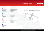
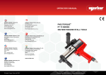
PROFESSIONAL SPRAYERS
USER’S MANUAL
Care and Maintenance
Safety Precautions
• Do not pressurize tank with external air or gas source; do not
pressurize above 50 psi.
• Do not adjust the tip or change spray patterns while depressing the valve trigger.
• Open tank cap slowly to release air before removing; keep
tank upright when releasing pressure.
• Do not store or transport the unit while tank is pressurized.
Before Starting
• Inspect the hose, tank gasket, discharge valves, and nozzle
for signs of wear or damage. These parts must be in full working condition to permit tank pressurization.
• It is recommended that compressed-air sprayers be used with
a pressure gauge (B&G #AG-3) or a pressure regulator (B&G
#460) fitted to the valve.
Operating Instructions
Filling and Mixing
• When mixing insecticides in the tank, first add about 1/2 the
water then the chemical, followed by the remainder of the
water required.
• Note gallon marks on the side of the tank and mix accordingly.
• Replace the pump and tank cap assembly, be sure the tank
gasket fits properly; tighten the cap until snug (do not over
tighten).
• Mix all insecticides according to label directions.
Pressurizing the Tank
• Disengage the handle from locked position by pressing down
and turning 1/4 turn to the left.
• Pump plunger up and down until desired pressure for application is achieved, then engage handle in the locked position.
Operation
B&G sprayers are designed for a variety of professional uses,
such as outdoor perimeter spraying, and indoor spraying, which
includes surface treatments and crack-and-crevice applications.
Application Rates*
50° coarse fan = 14.1 oz/min
80° fine fan = 6.4 oz/min
Pin stream = 8.9 oz/min (large)
4.5 oz/min (small)
*Calibrated at 20 psi
• Flush tank, valve, and extension with clean water regularly.
• Do not use bleach or ammonia-based cleaners, these will
damage the stainless steel and brass parts.
• After rinsing the tank with clean water, pressurize the tank
and flush the valve and hose.
• Inspect hoses and hose connections, gaskets, washers and
other fittings for wear; replace when necessary.
• Clean the filter at the hose/valve connection regularly.
• Do not use metal objects to clean the orifices in the nozzle,
this will disrupt the liquid spray pattern.
• Use the B&G Cleaning Kit (#22028000) for regular maintenance and cleaning of the sprayer.
Trouble Shooting
Problem: Tank not holding pressure
Solution: • Tighten tank cap
• Replace tank gasket (P-268)
Problem: Tank not getting air pressure
Solution: • Replace plunger cup (NPO-277)
• Replace or add oil to leather plunger cup
Problem: Pump cylinder filling with water when pumping
Solution: • Clean around the check valve at the bottom
of pump cylinder
• Replace the check valve (PV-266)
Problem: Holds pressure, but will not spray
Solution: • Nozzle clogged, clean with a soft brush
• Cracked siphon tube, replace
• Siphon tube clogged, clean end
• Clean strainer at the base of the valve, at the
hose / valve junction
Problem: Hose leaks at tank fitting
Solution: Replace hose washer (D-51-P)
Problem: Valve body leaking
Solution: • Extenda-Ban: Tighten packing nut, replace
packing washers (in D-124 Repair Kit)
• XR-Valve: Replace O-ring at base of handle;
replace copper gasket at base of valve stem
(in GT-100 Repair Kit)
• Ban-Drip: Tighten packing nut; replace rod
packing (RP-48)
Problem: Tip Leaking
Solution: • Extenda-Ban: Clean or replace soft seat gasket,
replace valve spring (in GD-124 Repair Kit)
• XR-Valve: Clean or replace check valve at end of
valve extension
• Ban-Drip: Clean or replace seat gasket; replace
rod spring (RS-49)
95138230 Rev 5/10
SPRAYER VALVES
Extenda-Ban Valve
Ban Drip Valve
Part #24 - Packing Nut:
PN-150
valve made before 1999
PN-150-1 valve made1999-2000
PN-150-2 valve made after 2000
BAN-DRIP VALVE
#
1
2
3
4
5
Part #
VB-40
VT-41
SA-42
SB-43
TS-44
Description
Valve body
Valve triggee
Mesh strainer
Pipe strainer
Trigger screw
#
9
10
11
12
13
Part #
RP-48
RS-49
SGH-50
TSG-51
TC-52
Description
Rod packing
Rod spring
Seat gasket holder
Seat gasket
Tip cap
6
7
8
TN-45
VR-46
PN-47
Trigger nut
Valve rod, pin
Brass packing nut
14A 800067 Fine fan tip
14B 5850
Multeejet assembly
XR VALVE
XR
Valve
#
1
2
3
4
5
Part #
22037500
22037510
22037503
22037508
22037501
Description
Valve assembly
XR Valve Kit
Handle
O-ring (Viton)
XR Valve body
EXTENDA-BAN VALVE
#
20
21
24
26
28
30
31
32
34
35
Part #
VB-147
VT-140
PN-150-2
VP-151
AS-148
SL-162
NG-146
MS-145-50
SA-143
VC-152
VC-153
VC-163
36 VE-154
VE-155
B&G Help Line
Description
Valve body
Valve Trigger Kit
Packing nut (s. steel)
Valve packing washer
Adjustment Screw Kit
Safety lock nut
Nylon gasket
Mesh Strainer Kit
Strainer housing
Valve cable, 9 in.
Valve cable, 18 in.
Valve cable, 24 in.
Valve extension, 8 in.*
Valve extension, 18 in.*
# Part #
36 VE-164
VE-154-SS
VE-155-SS
VE-164-SS
Description
Valve extension, 24 in.*
Valve extension, 8 in.**
Valve extension, 18 in.**
Valve extension, 24 in.**
37 VS-156
Valve spring
38 SSL-157
Seat stem nut
39 SS-158
Seat stem
40 SP-159
Soft seat gasket
41 5850-CC
Multeejet tip assembly
42 9751-M
Multeejet tip holder
43 4190
Viton gasket
44 5800-CC
Multeejet CC tip
45 4596
Tip retainer
* = brass ** = stainless steel
135 REGION SOUTH DRIVE • JACKSON, GA 30233
Toll Free 800-544-8811 • Phone 678-688-5601
www.bgequip.com • Fax 678-688-5633
800-544-8811
TANK AND HOSE
STAINLESS STEEL SPRAYER
#
1
2
3
4A
4D
5
6
7
8
Part #
T-50
T-100
T-200
T-300
T-500
HS-297
OS-297
TS-297
THS-297-01
FS-297
HA-298
TT-1
TB-1
5700-H
D-50
D-51-P
P-275
Description
Tank, 1/2 gal., 2 L
Tank, 1 gal., 4 L
Tank, 2 gal., 7.6 L
Tank, 3 gal., 11.3 L
Tank, 5 L
Siphon tube, 1/2 gal., 2 L
Siphon tube, 1 gal., 4 L
Siphon tube, 2 gal., 7.6 L
Siphon tube, 3 gal., 11.3 L
Siphon tube, 5 liter
Adapter, hose
Tank top (1 gal.)
Tank bottom
Tip holder
Hose, 4 ft. red
Hose washer
Pump handle
#
9
10
11
12
13
14
15
16
17
18
19
Part #
P-276
P-274
PH-273
PO-273
PF-265
PT-265
P-272
NP-277
NP-270
P-269A
P-269-SS
P-268
PH-267
PO-267
PF-267
PT-267
PV-266
Description
Pump lock spring
Pump cap
Plunger rod, 1/2 gal.
Plunger rod, 1 gal.
Plunger rod, 2 gal., 5 L
Plunger rod, 3 gal.
Back plate
Polypropylene cup
Cup spreader plate
Lock washer
Plunger nut
Pump gasket
Pump tube, 1/2 gal., 2 L
Pump tube, 1 gal., 4 L
Pump tube, 2 gal., 7.6 L
Pump tube, 3 gal., 11.3 L
Check valve
REPAIR AND MAINTENANCE MANUAL
Professional Pest Control Application Equipment
Prime Line Sprayers
EXTENDA-BAN VALVE REPAIR AND MAINTENANCE
Detach the Valve
and Extension
from the hose.
Carefully remove the mesh
strainer. Squeeze the
Trigger to drain all liquid
from the Valve.
1
Remove the Trigger (1), then the Snap ring (5),
Safety lock nut (6), the Adjustment screw (4), the
Lock nut (3), and then the Packing nut (2). The
Trigger can be removed by moving it to the back of the Valve.
2
Unscrew the
extension at
the front of the
valve. The extension can be
pulled away from the valve
along with the interior steel
cable.
3
Remove the
stainless steel
cable by pulling
it slowly through the back
end of the Extension –
you cannot pull the cable
through the front of the Extension. The threaded end of the
cable at the nozzle end is short and easily passes through
the curve in the Extension. The end of the cable at the
valve end is long and will not pass through the curve.
Replace the cable if it is worn or damaged.
7
Re-assemble
the Extension
by inserting
the short end of the
cable into the back so
that threads are exposed at the nozzle end.
8
9
Packing washers (white)
that were at the end of
the cable will remain
inside the valve. Carefully dislodge
and remove these washers.
Slide the Spring onto the end of the cable, then the
Seat stem lock nut. Screw lock nut to leave about
4 threads at the base of the end of the cable.
4
Remove the tip and
nozzle assembly from
the end of the extension, be careful to keep the Soft
seat gasket. Use 2 wrenches to
loosen the tip: one to hold the
extension, and a second to
loosen the tip. Note: the extension may become twisted and
unusable unless 2 wrenches are used
to remove the tip. Inspect the soft
seat gasket and the small O-ring on
Multeejet tips, replace if damaged or
worn. Replace the nozzle if it is more
than 2 years old.
Push the cable out the
front of the Extension
to expose the Spring,
the small Lock nut, and the Seat
stem. Unscrew the Seat stem
and Lock nut, and slide off the
Spring. Place these small pieces
in a closed container (they are
easily misplaced).
5
6
10
Attach the Seat stem onto the cable, in front of
the Lock nut. Hand tighten Seat stem against
the lock nut.
Insert the long end of the cable into the front
end of the valve. Push the cable through the
valve until the end is through the back of the
valve. Tighten Extension to the valve body.
11
STAINLESS STEEL SPRAYER
12
Insert 2 or
3 Packing
washers
onto the
cable, then
slide on the
Packing
nut behind
the washers and tighten.
• Valves built before 1999 have a stainless steel Packing
nut that takes 3/8 wrench, there is no internal O-ring,
these valves need 3 washers.
• Valves built between 1999 and 2000 have a brass
Packing nut + O-ring, this nut takes a 7/16 wrench,
these valves need 2 washers.
• Valves built after 2000 have a stainless steel Packing
nut + O-ring, this nut takes a 3/8 wrench, and these
valves require 3 washers.
Screw
onto the
cable the
Lock nut and the
Adjustment screw.
Turn the Adjustment
screw so the end of
the cable is level to
the top of the slot in the top of the screw. Tighten the Lock
nut against the screw.
13
14
Attach the valve trigger by inserting it into the
space between the Lock nut and Adjustment
screw, then insert the Trigger screw.
Screw the
Safety lock
nut into the
valve body, and then
attach the Snap ring.
15
Attach the tip and
nozzle to the end
of the Extension,
make certain the Soft seat
gasket is facing correctly.
The small end faces the
Extension. Press the Trigger
to retract the Seat stem into
the Extension, then attach the
tip and nozzle.
16
#
1
2
3
4A
4D
5
6
7
8
9
10
11
12
13
14
15
16
17
18
19
PART #
T-50
T-100
T-200
T-300
T-500
HS-297
OS-297
TS-297
THS-297-01
FS-297
HA-298
TT-1
TB-1
5700-H
D-50
D-51-P
P-275
P-276
P-274
PH-273
PO-273
PF-273
PT-273
P-272
NP-277
NP-270
P-269A
P-269-SS
P-268
PH-267
PO-267
PF-267
PT-267
PV-266
ORDER #
22024800
22025000
22025100
22025200
22025250
22025600
22025700
22025800
22025901
22025950
22025300
22049476
22049477
22049475
22030100
22030400
22029800
22029900
22029700
22029400
22029500
22029650
22029600
22029200
22029000
22028600
22028400
22028250
22028000
22027400
22027500
22027650
22027600
22027200
DESCRIPTION
Tank - 1/2 Gallon
Tank - 1 Gallon
Tank - 2 Gallon
Tank - 3 Gallon
Tank - 5 Liter
Siphon tube - 1/2 Gallon
Siphon tube - 1 Gallon
Siphon tube - 2 Gallon
Siphon tube - 3 Gallon
Siphon tube - 5 Liter
Adapter - hose
Tank top (1 Gallon)
Tank bottom
Tip holder
Hose - 4 ft. red
Hose washer
Pump handle
Pump lock spring
Pump cap
Plunger rod - 1/2 Gallon
Plunger rod - 1 Gallon
Plunger rod - 2 Gallon - 5 Liter
Plunger rod - 3 Gallon
Back plate
Polypropylene cup
Cup spreader plate
Lock washer
Plunger nut
Pump gasket
Pump tube - 1/2 Gallon
Pump tube - 1 Gallon
Pump tube - 2 Gallon
Pump tube - 3 Gallon
Check valve
TANK SPRAYER PROBLEMS AND SOLUTIONS
Problem: Tank holds pressure, but there
is no spray from nozzle (old sprayer).
Solution:
(1) Siphon tube is
clogged or cracked,
it must be cleaned
or replaced.
(2) Clean the mesh
Strainer at the end
of the hose near
the valve.
(3) Clean the nozzle with a small brush.*
(4) Clean or replace Soft seat gasket at the end of the
extension.
Problem: Valve is leaking around the Packing
nut, and the handle is
wet.
Solution:
(1) Tighten the Packing
nut.
(2) Replace the valve
Packing washers.
2 washers with brass
Packing nut
3 washers with stainless steel Packing nut
*These parts are in Gasket Kit GD-124
Problem: Tank is not holding pressure; pump is working
but no pressure remains in the tank.
Solution: Check Pump gasket, replace if cracked.
Problem: Extension is leaking at the tip, a constant drip
from the tip.
Solution:
(1) Clean or replace
nozzle O-ring.
(2) Clean end of Seat stem.
(3) Clean or replace Soft seat
gasket.
(4) Replace the Valve spring.
Problem: Tank is not getting pressure; the pump seems to
be working but no pressure builds in the tank.
Solution: Grease Plastic cup in pump tube, or replace cup
and Spreader Plate.
Problem: Pump cylinder fills with liquid, pumping is
difficult.
Solution: Clean dirt from bottom of pump tube, replace
Check valve at bottom.
Problem: Won’t spray; tank holds pressure but there is no
spray from the nozzle, a new sprayer.
Solution: Replace Hose washer, it may have been
damaged when hose was attached to tank; the junction
may have been over-tightened!
REV 6/09
Problem: Hose is leaking at the
connection with the tank; leaks
when tank is pressurized.
Solution: Replace the Hose
washer at the end of the hose;
do not over-tighten the connection when reconnecting the
hose to the tank.
*B&G Sprayer Cleaning Kit