1
Digital Temperature Controllers
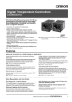
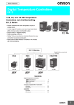
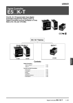
E5CZ
Next-generation Digital Temperature
Controller
• Depth of only 78 mm.
• Various temperature inputs: thermocouple, platinum resistance
thermometer, infrared temperature sensor, and analog inputs.
• Auto-tuning and self-tuning are available. Auto-tuning is possible even while self-tuning is being executed.
• Heating or heating/cooling control is available.
• Start/stop function.
• CE marking and UL/CSA approval.
• Models with optional functions and current output added to the
series.
48 × 48 × 78 mm (W × H × D)
®
Refer to the "Safety Precautions" on page 52.
Model Number Structure
■ Model Number Legend
E5CZ- @ 2 @ @
1 2 3
4
1. Output type
R:
Relay
Q:
Voltage (for driving SSR)
C:
Current
2. Number of alarms
2:
Two alarms
3. Option Unit
Blank: Not available
M:
Option Unit can be mounted
4. Power supply voltage
Blank: 100 to 240 VAC
D:
24 VAC/VDC
Ordering Information
■ List of Models
Size
Power supply
voltage
1/16 DIN
100 to 240 VAC
48 × 48 × 78 mm (W × H × D)
24 VAC/VDC
Number of
alarm points
2
2
Control output
Option Unit
Model
Relay
Not Available
E5CZ-R2
Voltage for driving SSR
Not Available
E5CZ-Q2
Relay
Available
E5CZ-R2M
Voltage for driving SSR
Available
E5CZ-Q2M
Current
Available
E5CZ-C2M
Relay
Available
E5CZ-R2MD
Voltage for driving SSR
Available
E5CZ-Q2MD
Current
Available
E5CZ-C2MD
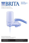
■ Option Units
The E5CZ-@2M provides communications or event input functionality when one of the following Option Units is mounted.
Functions
Communications
Heater burnout
Communications
E53-CN03N
Heater burnout
12
Model
E53-CNH03N
Event inputs
E53-CNHBN
Event inputs
E53-CNBN
Digital Temperature Controllers E5CZ
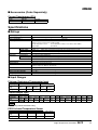
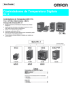
■ Accessories (Order Separately)
Current Transformers (CTs)
Model
E54-CT1
E54-CT3
Hole diameter
5.8 dia.
12.0 dia.
Specifications
■ Ratings
Power supply voltage
100 to 240 VAC, 50/60 Hz
Operating voltage range
85% to 110% of rated supply voltage
Power consumption
7 VA
Sensor input
Thermocouple:
K, J, T, E, L, U, N, R, S, B
Platinum resistance thermometer: Pt100, JPt100
Infrared temperature sensor:
10 to 70°C, 60 to 120°C, 115 to 165°C, 140 to 260°C
Voltage input:
0 to 50 mV
Control output
24 VAC/VDC, 50/60 Hz
5 VA, 3 W
Relay output
SPST-NO, 250 VAC, 3 A (resistive load), electrical life: 100,000 operations
Voltage output
12 VDC +15%/−20% (PNP), max. load current: 21 mA, with short-circuit protection circuit
Current output
Alarm output
4 to 20 mA DC, load: 600 Ω max., resolution: approx. 2,600
SPST-NO, 250 VAC, 1 A (resistive load), electrical life: 100,000 operations
Event input
ON: 1 kΩ max., OFF: 100 kΩ min.
Contact input
Non-contact input ON: Residual voltage: 1.5 V max., OFF: Leakage current: 0.1 mA max.
Outflow current: Approx. 7 mA per point
Control method
2-PID control or ON/OFF control
Setting method
Digital setting using front panel keys
Indication method
7-segment digital display and single-lighting indicators
Character height: PV: 10.0 mm; SV: 6.5 mm
Other functions
According to Controller model
Ambient operating temperature
−10 to 55°C (with no condensation or icing)
Ambient operating humidity
25% to 85%
Storage temperature
−25 to 65°C (with no condensation or icing)
■ Input Ranges
Platinum Resistance Thermometer Input
Input type
Temperature
range
Pt100
−200 to
850°C
Setting number 0
JPt100
−199.9 to
500.0°C
0.0 to
100.0°C
−199.9 to
500.0°C
0.0 to
100.0°C
1
2
3
4
Thermocouple Input
Input type
Temperature
range
K
J
−200 to −20 to
1300°C 500°C
Setting number 5
6
T
E
L
U
N
R
S
B
−100 to −20.0 to −200 to −199.9 to 0 to
850°C 400.0°C 400°C 400.0°C 600°C
−100 to −200 to −199.9 to −200 to 0 to
0 to
100 to
850°C 400°C 400.0°C 1300°C 1700°C 1700°C 1800°C
7
11
8
9
22
10
12
23
13
14
15
16
Shaded setting indicates the default setting.
ES1B Infrared Temperature Sensor
Input type
Temperature
range
10 to 70°C
0 to 90°C
Setting number 17
60 to 120°C
115 to 165°C
140 to 260°C
0 to 120°C
0 to 165°C
0 to 260°C
18
19
20
Digital Temperature Controllers
E5CZ
13
Analog Input
Input type
0 to 50 mV
Setting range
Usable in the following ranges by scaling:
−1999 to 9999 or −199.9 to 999.9
Setting number 21
Applicable standards by input type are as follows:
K: GB/T 2814-98
J,L: GB/T 4994-98
T,U: GB/T 2903-98
E: GB/T 4993-98
N: GB/T 17615-98
R: GB/T 1598-98
S: GB/T 3772-98
B: GB/T 2902-99
JPt100, Pt100: GB/T 5977-99
■ Characteristics
Indication accuracy
Thermocouple:
(±0.5% of indicated value or ±1°C, whichever is greater) ±1 digit max. (See note 1.)
Platinum resistance thermometer:
(±0.5% of indicated value or ±1°C, whichever is greater) ±1 digit max.
Analog input: ±0.5% FS±1 digit max.
CT input: ±5% FS±1 digit max.
Influence of temperature
(See note 2.)
R, S, and B thermocouple inputs:
(±1% of PV or ±10°C, whichever is greater) ±1 digit max.
Other thermocouple inputs:
(±1% of PV or ±4°C, whichever is greater) ±1 digit max.
*±10°C for −100°C or less for K sensors
Platinum resistance thermometer inputs:
(±1% of PV or ±2°C, whichever is greater) ±1 digit max.
Analog inputs:
(±1% of FS) ±1 digit max.
Influence of voltage
(See note 2.)
Hysteresis
0.1 to 999.9 EU (in units of 0.1 EU)
Proportional band (P)
0.1 to 999.9 EU (in units of 0.1 EU)
Integral time (I)
0 to 3999 s (in units of 1 s)
Derivative time (D)
0 to 3999 s (in units of 1 s)
Control period
1 to 99 s (in units of 1 s)
Manual reset value
0.0% to 100.0% (in units of 0.1%)
Alarm setting range
−1999 to 9999 (decimal point position depends on input type)
Sampling period
500 ms
Insulation resistance
20 MΩ min. (at 500 VDC)
Dielectric strength
2,000 VAC, 50 or 60 Hz for 1min (between current-carrying terminals of different polarity)
Vibration resistance
10 to 55 Hz, 20 m/s2 for 10 min in X, Y and Z directions
Shock resistance
100 m/s2, 3 times each in 3 axes, 6 directions
Weight
Approx. 150 g
Memory protection
EEPROM (non-volatile memory) (number of write operations: 100,000)
EMC
Enclosure Emission:
AC Mains Emission:
ESD Immunity:
Applicable standards
UL 61010C-1, CSA C22.2 No.1010.1
Conforms to EN 61326, EN 61010-1 (IEC 61010-1).
EN 55011 (GB/T 6113.1,2) Group 1 Class A
EN 55011 (GB/T 6113.1,2) Group 1 Class A
IEC 61000-4-2 (GB/T 17626.2) 4 kV contact discharge (level 2)
8 kV air discharge (level 3)
RF-interference Immunity:
IEC 61000-4-3 (GB/T 17626.3): 10 V/m, 80 MHz to 1 GHz (level 3)
Conducted Disturbance Immunity: IEC 61000-4-6 (GB/T 17626.6): 3 V (0.15 to 80 MHz) (level 3)
Burst Immunity:
IEC 61000-4-5 (GB/T 17626.5): 2 kV powerline (level 3)
2 kV I/O signalline (level 4)
Note 1. The indication accuracy of K thermocouples in the −200 to 1300°C range, T and N thermocouples at a temperature of −100°C max. and
U and L thermocouples at any temperature is ±2°C ±1 digit maximum. The indication accuracy of the B thermocouples at a temperature
of 400°C max. is not specified.
The indication accuracy of the R and S thermocouples at a temperature of 200°C max. is ±3°C ±1 digit maximum.
2. Conditions: Ambient temperature: −10°C to 23°C to 55°C, Voltage range: −15% to +10% of rated voltage.
3. When using the E53-CN03N or E53-CNBN Option Unit with the E5CZ-C2M or E5CZ-C2M to satisfy the Class A limit for the radiated interference field strength test, always connect a ZCAT2235-1030 Clamp Filter (manufactured by TDK) to the power line of the Temperature
Controller.
14
Digital Temperature Controllers E5CZ
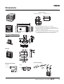
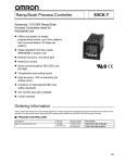
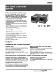
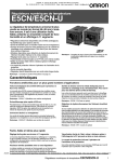
Dimensions
Note: All units are in millimeters unless otherwise indicated.
Panel Cutouts
Group Mounted
Mounted separately
(48 × No. of units −2.5) +1.0
0
ALM1
ALM2
PV
45 +0.6
0
OUT1 STO
P
OUT2
60 min
SV
45 +0.6
0
45 +0.6
0
E5CZ
102
93
48
ALM1
e
78
6
Recommended panel thickness is 1 to 8 mm.
Group mounting is not possible in the vertical direction.
(Maintain the specified mounting space between Controllers
when they are group mounted.)
PV
SV
58
OUT2
48.8
OUT1 STOP
48.8
ALM2
When two or more Controllers are mounted, make sure that
the surrounding temperature does not exceed the allowable
operating temperature specified in the specifications.
E5CZ
Current Transformers
21
15
2.8
5.8 dia.
E54-CT1
7.5
25
3
10.5
40
Two, 3.5 dia.
10
30
E54-CT3
2.36 dia.
30
12 dia.
9
40@
Two, M3 holes (depth: 4)
15
30
Connection Example
E54-CT3 Accessories
• Contact
Contact
Plug
• Plug
Lead wire
Approx. 3 dia.
Approx. 6 dia.
(22)
18
Digital Temperature Controllers
E5CZ
15
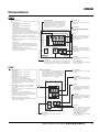
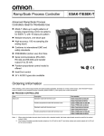
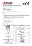
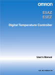
Wiring Terminals
• The voltage output (control output) is not electrically insulated from the internal circuits. When using a grounded thermocouple, do not connect
the control output terminals to the ground. If the control output terminals are connected to the ground, errors will occur in the measured temperature values as a result of leakage current.
Current output
Control output 1
Voltage output
Alarm output
Relay output
12 VDC
21 mA
4 to 20 mA DC
ALM2/Control
output 2
Analog input
ALM1/Heater
burnout
Input power supply
Two input power supplies are available: 100 to 240 VAC or 24 VDC.
Option Units
E53-CNHBN
Event Inputs/Heater Burnout Detection
Contact inputs
Non-contact inputs
Heater burnout detection input
E53-CNBN
Event Inputs
Contact inputs Non-contact inputs
Do not use.
Do not use.
E53-CNH03N
Communications/Heater Burnout Detection
B (+)
A (−)
Do not use.
Host computer
A (−)
RS-485
Host computer
RS-485
B (+)
E53-CN03N
Communications
Do not use.
Heater burnout detection input
Do not use.
Do not use.
Communications
Interface:
RS-485
Synchronization: Start-stop
(asynchronous)
Communications: Half duplex
Baud rate:
1.2/2.4/4.8/9.6/
19.2 kbps
16
Event Inputs
Contact Inputs
ON: 1 kΩ max., OFF: 100 kΩ min.
Non-Contact Inputs
ON: residual voltage of 1.5 V max.
OFF: leakage current of 0.1 mA max.
Digital Temperature Controllers E5CZ
Heater Burnout Alarm
Maximum heater current: 50 A AC
Input current indication accuracy:
±5% FS ±1 digit max.
Heater burnout alarm setting range:
0.1 to 49.9 A, in 0.1 A increments
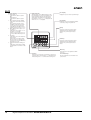
Nomenclature
E5AZ
Operation Indicators
1. ALM1 (alarm 1)
Lights when the alarm 1 output is ON.
ALM2 (alarm 2)
Lights when the alarm 2 output is ON.
ALM3 (alarm 3)
Lights when the alarm 3 output is ON.
Temperature Unit
The temperature unit is displayed when the display unit parameter is set to a temperature. Indication is determined by the currently selected
"temperature unit" parameter set value. When
this parameter is set to "°C," "c" is displayed,
and when set to "°F," "f" is displayed.
4. STOP (stop)
Lights when control of the E5AZ has been stopped.
During control, this indicator lights when an event or the
run/stop function has become stopped. Otherwise, this
indicator is not lit.
Displays the process value or parameter type.
No. 2 Display
Displays the set point, manipulated
variable, or set value (setup) of the
parameter.
2. HB (heater burnout alarm display)
Lights when a heater burnout is detected.
The heater burnout alarm can be held ON by setting the
heater burnout latch. To reset, turn the power supply
OFF and then ON or set the heater burnout alarm value
to 0.0 A.
3. OUT1, OUT2 (control output 1, control output 2)
Lights when control output 1 or control output 2 (cool) is
ON.
However, if control output 1 is a current output, OUT1
will always be not lit.
No. 1 Display
Up Key
ALM1
ALM2
PV
ALM3
HB
Each press of this key increases values displayed on the No.2 display.
Holding down this key continuously
increases values.
OUT1
OUT2
SV
STOP
CMW
Down Key
Each press of this key decreases values displayed on the No.2 display.
Holding down this key continuously decreases values.
5. CMW (communications writing control)
Lights when communications writing is enabled and is
not lit when it is disabled.
E5AZ
Level Key
Press this key to select the setup level. The setup level is
selected in order "operation level" ←→ "adjustment level,"
"initial setting level" ←→ "communications setting level."
Mode Key
Press this key to select parameters
within each level.
Level + Mode Keys
This key combination sets the E5AZ
to the "protect level."
E5EZ
Operation Indicators
1. ALM1 (alarm 1)
Lights when the alarm 1 output is ON.
ALM2 (alarm 2)
Lights when the alarm 2 output is ON.
ALM3 (alarm 3)
Lights when the alarm 3 output is ON.
Temperature Unit
No. 1 Display
The temperature unit is displayed when the display unit parameter is set to a temperature. Indication is determined by the currently selected
"temperature unit" parameter set value. When
this parameter is set to "°C," "c" is displayed,
and when set to "°F," "f" is displayed.
Displays the process value or parameter type.
3.
OUT1, OUT2 (control output 1, control output 2)
Lights when control output 1 or control output 2
(cool) is ON.
However, if control output 1 is a current output, OUT1
will always be not lit.
PV
ALM1 ALM2 ALM3
Up Key
Each press of this key increases values displayed on the No.2 display.
Holding down this key continuously
increases values.
HB
4. STOP (stop)
Lights when control of the E5EZ has been
stopped.During control, this indicator lights when an
event or the run/stop function has become stopped.
Otherwise, this indicator is not lit.
5. CMW (communications writing control)
Lights when communications writing is enabled and
is not lit when it is disabled.
No. 2 Display
Displays the set point, manipulated
variable, or set value (setup) of the parameter.
2. HB (heater burnout alarm display)
Lights when a heater burnout is detected.
The heater burnout alarm can be held ON by setting
the heater burnout latch. To reset, turn the power
supply OFF and then ON or set the heater burnout
alarm value to 0.0 A.
Down Key
OUT1 OUT2 STOP CMW
SV
E5EZ
Mode Key
Press this key to select parameters within
each level.
Digital Temperature Controllers
Each press of this key decreases values displayed on the No.2 display.
Holding down this key continuously
decreases values.
Level Key
Press this key to select the setup level. The setup level is selected in order
"operation level" ←→ "adjustment
level," "initial setting level" ←→
"communications setting level."
Level + Mode Keys
This key combination sets the E5EZ
to the "protect level."
E5AZ/E5EZ/E5CZ
17
E5CZ
Operation Indicators
Temperature Unit
No. 1 Display
1. ALM1 (alarm 1)
Lights when the alarm 1 output is
ON.
ALM2 (alarm 2)
Lights when the alarm 2 output is
ON.
2. HB (heater burnout alarm display)
Lights when a heater burnout is detected.
The heater burnout alarm can be
held ON by setting the heater burnout latch. To reset, turn the power
supply OFF and then ON or set the
heater burnout alarm value to 0.0 A.
3. OUT1, OUT2 (control output 1, control output 2)
Lights when control output 1 or control output 2 (cool) is ON.
However, if control output 1 is a current output, OUT1 will always be not
lit.
4. STP (stop)
Lights when control of the E5CZ has
been stopped.
During control, this indicator lights
when an event or the run/stop function has become stopped. Otherwise,
this indicator is not lit.
5. CMW (communications writing control)
Lights when communications writing
is enabled and is not lit when it is disabled.
The temperature unit is displayed when the display unit parameter is set to a temperature. Indication is determined by the currently selected
"temperature unit" parameter set value. When
this parameter is set to "°C," "c" is displayed, and
when set to "°F," "f" is displayed.
Displays the process value or parameter type.
No. 2 Display
Displays the set point, manipulated variable,
or set value (setup) of the parameter.
Up Key
Each press of this key increases values
displayed on the No.2 display. Holding
down this key continuously increases
values.
ALM1
PV
ALM2
HB
OUT1 STOP
SV
OUT2 CMW
Down Key
Each press of this key decreases values
displayed on the No.2 display. Holding
down this key continuously decreases
values.
E5CZ
Mode Key
Level Key
Press this key to select the setup level. The setup level is
selected in order "operation level" ←→ "adjustment level,"
"initial setting level" ←→ "communications setting level."
18
Digital Temperature Controllers E5AZ/E5EZ/E5CZ
Press this key to select parameters within
each level.
Level + Mode Keys
This key combination sets the E5CZ to the
"protect level."
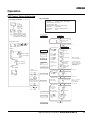
Operation
PID Control Using Autotuning
Typical Example
Changing Parameters
Input type:
4 T thermocouple −200 to 400°C
Control method: PID control
ST (self-tuning): OFF
Calculate PID constants by AT (auto-tuning).
indicates that there is a parameter. Keep on pressing
the mode key until the desired parameter is selected.
Alarm type:
2 upper limit
Alarm value 1:
30°C (For setting deviation)
Set point:
150°C
Setup procedure
Power ON
Power ON
Operation level
Process value/
set point
Changing Set Values
Use the
or
keys
to change the set value
displayed in the setup
menu.
Press key for at least three
seconds.
Control stops.
Display
Set input
specifications
E5AZ
No. 1 display
No. 2 display
E5EZ
In PID control
Press
keys to select
PID control.
Self-tuning
Press
keys to set
ST to OFF.
To cancel ST
When set to ON,
self-tuning operates.
Check the
control period.
Control period
(heat) (unit:
seconds)
Check alarm type
Check alarm
type.
Alarm 1 type 2
(upper-limit
alarm)
Recommended settings: 20 seconds for
the relay output and
2 seconds for the
SSR output.
Set the set point
Operation level
Press
keys
to set set point to
"150°C."
Check control
period
E5CZ
No. 1 display
PV/SP
Press
After AT execution.
No. 2 display
Input type 4
Set control
specifications
No. 1 display
No. 2 display
Initial setting level
Press
keys to select
input type.
key for at least one second.
PV/
SP 150
During AT execution.
Press key for less than one second.
Adjustment level
While AT is being
executed, SP will flash.
AT execution
Execute AT
(auto-tuning).
To execute AT
After AT execution.
Set to on for executing AT and to off
for stopping AT.
Press key for less than one second.
Operation level
During AT execution.
Make sure
that set point
is "150°C."
Set operation status
Set alarm values
Start operation
PV/
SP150
Make sure that
control is running.
During run
Press
keys to set
alarm value to
"30°C."
Alarm
value 1
30
Start operation
Digital Temperature Controllers
E5AZ/E5EZ/E5CZ
19
■ Specification Setting after Turning ON Power
Outline of Operation Procedures
Key Operation
In the following descriptions, all the parameters are introduced in the display sequence. Some parameters may not be displayed depending on the
protect settings and operation conditions.
Power ON
Operation level
Adjustment level
key
Less than
1 second
key
1 second
min.
key
3 seconds
min.
Initial setting level
+
key
Display flashes when key pressed.
+
key
1 second min.
key
Display flashes when key held
down for more than 1 second.
Control stops.
Communications setting
level
key
Less than
1 second
+
key
3 seconds min.
Protect level
Password input
set value "−169"
key
1 second min.
Advanced function
setting level
Control in progress
Control stopped
The time taken to move to the protect level
can be adjusted by changing the "Move to
protect level time" setting.
Note: Of these levels, the initial setting level, communications setting level, advanced function setting level and calibration
level can be used only when control has stopped. Note that
control is stopped when these four levels are selected.
When switched back to the operation level from one of
these levels, control will start.
Level change
Description of Each Level
Operation Level
Protect Level
This level is displayed when you turn the power ON. You can move to
the protect level, initial setting level and adjustment level from this
level.
To select this level, simultaneously press the
and M keys for at
least 3 seconds. This level is to prevent unwanted or accidental modification of parameters. Protected levels will not be displayed, and so
the parameters in that level cannot be modified.
Normally, select this level during operation. During operation, the
process value, set point and manipulated variable can be monitored,
and the alarm value and upper- and lower-limit alarms can be monitored and modified.
Adjustment Level
To select this level, press the
key once for less than one second.
This level is for entering set values and offset values for control. This
level contains parameters for setting the set values, AT (auto-tuning),
communications writing enable/disable, hysteresis, multi-SP, input
shift values, heater burnout alarm (HBA) and PID constants. You can
move to the top parameter of the operation level or initial setting level
from here.
Initial Setting Level
To select this level, press the
key for at least three seconds in the
operation level. This level is for specifying the input type, selecting
the control method, control period, setting direct/reverse action and
alarm type. You can move to the advanced function setting level or
communications setting level from this initial setting level. To return to
Communications Setting Level
To select this level, press the
key once for less than one second in
the initial setting level. When the communications function is used,
set the communications conditions in this level. Communicating with
a personal computer (host computer) allows set points to be read
and written, and manipulated variables to be monitored.
Advanced Function Setting Level
To select this level, you must enter the password (“-169”) in the initial
setting level.
You can move only to the calibration level from this level.
This level is for setting the automatic return of display mode, MV limiter, event input assignment, standby sequence, alarm hysteresis, ST
(self-tune) and to move to the user calibration level.
the operation level, press the
key for at least one second. To
move to the communications setting level, press the
key once for
less than one second.
20
Digital Temperature Controllers E5AZ/E5EZ/E5CZ
Specification Setting after Turning ON Power
Initial Setting Level
Initial setting level
This level is used for setting basic specifications of the Temperature
Controller. Using this level, set the input type for selecting the input to
be connected such as the thermocouple or platinum resistance thermometer and set the range of set point and the alarm mode.
Input type
Scaling upper limit
key
+
Display flashes
when key pressed.
Power ON
Operation level
Adjustment level
key
Less than 1 second
key
1 second min.
key
3 seconds
min.
Initial setting
level
key
1 second min.
Scaling lower limit
key
+
1 second min.
Decimal point
key
+
3 seconds
min.
Control stops.
Temperature
unit
Communications setting
key level
Less than 1 second
Password input
set value "−169"
Advanced function
setting level
For analog input
Protect level
SP upper limit
The time taken to move
to the protect level can
be adjusted by changing
the "Move to protect level time" setting.
SP lower limit
Control in progress
Control stopped
PID ON/OFF
Level change
The move from the operation level to the initial setting level, press
key for three seconds or more.
Standard or heating/
cooling
Alarm output type
The initial setting level is not displayed when “initial/communications
protection” is set to “2.” This initial setting level can be used when
“initial setting/communications protection” is set to “0” or “1.”
ST
(PID control)
The “scaling upper limit,” “scaling lower limit,” and “decimal point”
parameters are displayed when an analog voltage input is selected
as the input type.
Control period (heating)
Control period (cooling)
(PID control)
(Heating/cooling setting)
Set the pulse output
cycle.
Direct/reverse operation
Alarm 1 type
Alarm 2 type
Select the alarm mode.
(Models with alarm
function)
Alarm 3 type
Move to advanced
function setting level
(Displayed when initial setting/communications protection
is set to 0.)
To return to the operation level, press the
second.
*
key for longer than one
Not displayed as default setting.
Digital Temperature Controllers
E5AZ/E5EZ/E5CZ
21
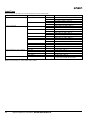
Input Type
When selecting the input type, follow the specifications listed in the following table.
Specifications
Platinum resistance thermometer input
Thermocouple input
Pt100
1
−199.9 to 500.0 (°C)/−199.9 to 900.0 (°F)
0.0 to 100.0 (°C)/0.0 to 210.0 (°F)
JPt100
3
−199.9 to 500.0 (°C)/−199.9 to 900.0 (°F)
4
0.0 to 100.0 (°C)/0.0 to 210.0 (°F)
K
5
−200 to 1300 (°C)/−300 to 2300 (°F)
6
−20.0 to 500.0 (°C)/0.0 to 900.0 (°F)
J
7
−100 to 850 (°C)/−100 to 1500 (°F)
8
−20.0 to 400.0 (°C)/0.0 to 750.0 (°F)
9
−200 to 400 (°C)/−300 to 700 (°F)
22
−199.9 to 400.0 (°C)/199.9 to 700.0 (°F)
10
0 to 600 (°C)/0 to 1100 (°F)
L
11
−100 to 850 (°C)/−100 to 1500 (°F)
U
12
−200 to 400 (°C)/−300 to 2300 (°F)
23
−199.9 to 400.0 (°C)/199.9 to 700.0 (°F)
E
Analog input
N
13
−200 to 1300 (°C)/−300 to 2300 (°F)
R
14
0 to 1700 (°C)/0 to 3000 (°F)
S
15
0 to 1700 (°C)/0 to 3000 (°F)
B
16
100 to 1800 (°C)/300 to 3200 (°F)
10 to 70°C
17
0 to 90 (°C)/0 to 190 (°F)
60 to 120°C
18
0 to 120 (°C)/0 to 240 (°F)
115 to 165°C
19
0 to 165 (°C)/0 to 320 (°F)
140 to 260°C
20
0 to 260 (°C)/0 to 500 (°F)
0 to 50 mV
21
One of the following ranges depending on the results
of scaling: 1999 to 9999, 199.9 to 999.9
Note: The initial setting is 5: −200 to 850°C/−300 to 2300°F.
22
Input Temperature Range
−200 to 850 (°C)/−300 to 1500 (°F)
2
T
Infrared Temperature Sensor (ES1B)
Set Value
0
Digital Temperature Controllers E5AZ/E5EZ/E5CZ
Alarm Types
Select the alarm type from the 12 types listed in the following table.
Set Value
Alarm Type
Alarm Output Operation
When X is positive
When X is negative
0
Alarm function OFF
Output OFF
1 (See note 1.)
Upper- and lower-limit (deviation)
2
Upper-limit (deviation)
3
Lower-limit (deviation)
4 (See note 1.)
Upper- and lower-limit range (deviation)
(See note 3.)
5 (See note 1.)
Upper- and lower-limit with standby sequence (deviation)
(See note 4.)
6
Upper-limit with standby sequence (deviation)
7
Lower-limit with standby sequence (deviation)
8
Absolute-value upper-limit
9
Absolute-value lower-limit
10
Absolute-value upper-limit with standby
sequence
11
Absolute-value lower-limit with standby
sequence
(See note 2.)
(See note 5.)
Note 1: With set values 1, 4 and 5, the upper and lower limit values
can be set independently for each alarm type, and are expressed as “L” and “H.”
Following operations are for cases when an alarm set point
is “X” or negative.
2: Set value: 1, Upper- and lower-limit alarm
Case 1
Case 2
Case 3 (Always ON)
=
=
3: Set value: 4, Upper- and lower-limit range
Case 1
Case 2
5: Set value: 5, Upper- and lower-limit with standby sequence
alarm. Always OFF when the upper-limit and lower-limit hysteresis overlaps.
Set the alarm types for alarm 1 and alarm 2 independently in
the initial setting level. The default setting is 2 (upper limit).
With the E5AZ/E5EZ, perform settings similarly for alarm 3.
Example: When the alarm is set ON at 110°C/°F or higher.
When an alarm type other
When the absolute-value
than the absolute-value
alarm is selected
alarm is selected
(For alarm types 8 to 11)
(For alarm types 1 to 7)
The alarm value is set as
The alarm value is set as a
an absolute value from the
deviation from the set point.
alarm value of 0°C/F.
Alarm value
Alarm value
Case 3 (Always OFF)
L H
=
Set point
100°C/°F
0°C/°F
=
4: Set value: 5, Upper- and lower-limit with standby sequence
Case 1
Case 2
Example
Same as for the upper- and lower-limit
alarm. However, when the upper-limit
and lower-limit hysteresis overlaps:
Always OFF
Digital Temperature Controllers
E5AZ/E5EZ/E5CZ
23
Parameters
key 1 s min.
Parameters related to setting items for each level are marked in
boxes in the flowcharts and brief descriptions are given as required.
At the end of each setting item, press the mode key to return to the
beginning of each level.
Power ON
Resets to the default value.
Parameter initialization
Number of multi-SP uses
Select 2 or 4.
+ key
Display flashes
when key pressed.
Operation level
Event input assignment 1
Adjustment level
key
Less than 1 s
key
1 s min.
Advanced Function Setting Level
key
3 s min.
+
key
1 s min.
+
key
Display flashes when key held
down for more than 1 s.
Control stops.
Initial setting level
Event input assignment 2
Multi-SP uses
+
3 s min.
key
SP ramp set value
Rate of change during ramp
Communications setting
key level
Standby sequence reset method
Restarting condition
after clearing standby
Protect level
Less than 1 s
key
The time taken to
move to the protect
level can be adjusted
by changing the "Move
to protect level time"
setting.
Password input
set value "−169"
1 s min.
Advanced function
setting level
Input setting:
Multi-SP/RUN/STOP
Alarm 1 open in alarm
Alarm 1 hysteresis
Control in progress
ON/OFF setting of
alarm output 1
Alarm 2 open in alarm
ON/OFF setting of
alarm output 2
Control stopped
Level change
Alarm 2 hysteresis
Display
Alarm 3 open in alarm
ON/OFF setting of
alarm output 3
E5AZ
Alarm 3 hysteresis
No. 1 display
Heater burnout detection
No. 2 display
Heater burnout latch
Latch after heater
burnout detection
Heater burnout hysteresis
E5EZ
ST stable range
For setting deviation.
No. 1 display
α
2-PID parameter
No. 2 display
MV upper limit
E5CZ
Limitations to MV
No. 1 display
MV lower limit
No. 2 display
Input digital filter
Additional PV display
Displayed first in the operation level
MV display
Move to protect level time
Automatic return of display mode
Input error output
Cold junction
compensating method
Alarm 1 ON delay
Alarm 2 ON delay
Alarm 3 ON delay
Alarm 1 OFF delay
Alarm 2 OFF delay
Alarm 3 OFF delay
24
Note: To select advanced
function setting
level, you must
enter the password
("−169") in the initial
setting level.
Digital Temperature Controllers E5AZ/E5EZ/E5CZ
Alarm
ON/OFF
delays
MB command logic
switching
Power ON
key 1 s min.
key Less than 1 s
Operation Level
Initial Setting Level
Adjustment Level
key Less than 1 s
key 3 s min.
Process value
Input type
Scaling upper limit
Add in the "additional
PV display" parameter.
Communications writing
Process value/set point
For analog input
Scaling lower limit
c: °C
f: °F
Heater current value monitor
SP upper limit
HBA function
Heater burnout
detection
SP ramp monitor
Number of displayed digits
Temperature unit
Heater current
value monitor
Multi-SP
set point setting
Decimal point
AT execute/cancel
SP 0
SP 1
Run/stop
SP used by multi-SP
Limit the set point.
SP lower limit
PID ON/OFF
Upper-limit
alarm value 1
Select the control system.
Standard or heating/cooling
Set either of
these
parameters.
Lower-limit
alarm value 1
ST
Alarm value 2
Control period (heating)
OUT1
Control period (cooling)
OUT2
SP 2
Alarm value 1
Set the pulse
output cycle.
Upper-limit
alarm value 3
Select the alarm
mode.
1-point shift
Upper-limit
temperature input
2-point shift (see note)
Lower-limit
temperature input
Integral time
Alarm value 3
Alarm 1 type
Temperature input shift
Proportional band P
Lower-limit
alarm value 2
Direct/reverse operation
Controls the MV in response
increases or decreases in the PV.
Alarm 2 type
Upper-limit
alarm value 2
Set either of
these
parameters.
SP 3
I
PID settings
Set either of
these
parameters.
Lower-limit
alarm value 3
Derivative time
D
Cooling coefficient
Dead band
Used in heating and
cooling control
MV monitor (heating)
Alarm 3 type
Move to advanced function
setting level
Note: This parameter is not displayed as a default setting. To move to the advanced function setting
level, change the initial setting/communications
protection setting from 1 to 0. (See page 26.)
Manual reset value
MV monitor (cooling)
Clear the offset
during stabilization
of P or PD control.
Hysteresis (heating)
The displays for parameters which can be
switched (i.e., parameters other than simply
numerical ones) show the contents of those
parameters.
Set hysteresis.
Hysteresis (cooling)
The 2-point shift setting is only possible when the
input type is an infrared temperature sensor.
Note: These diagrams show all the parameters that may be displayed. Depending on the specifications of the model used, there may be some
parameters that are not displayed.
Input Shift
All points in the sensor range are shifted by the value set as the temperature input shift value.
Example
Input shift setting
Temperature
measured by
sensor
0 (no shift)
100°C
10 (shifted +10°C)
100°C
−10 (shifted −10°C) 100°C
Temperature
display
100°C
110°C
90°C
Digital Temperature Controllers
E5AZ/E5EZ/E5CZ
25
Protect Level
Operation/adjustment protection
Restricts displaying and modifying menus in operation,
adjustment, and manual control levels.
Initial setting/communications protection
This protect level restricts movement to the initial setting,
communications setting, and advanced function setting levels.
Setting change protection
Protects changes to setups by operating the front panel
keys.
Operation/Adjustment Protection
The following table shows the relationship between set values and
the range of protection.
Level
Operation level
Set value
PV
0
1
2
3
❍
❍
❍
❍
❍
PV/SP
Other
Adjustment level
X
X
X
X
X
When this parameter is set to “0,” parameters are not protected.
Default setting: 0
: Can be displayed and changed
❍: Can be displayed
X : Cannot be displayed and move to other levels not possible
Initial Setting/Communications Protection
This protect level restricts movement to the initial setting level, communications setting level and advanced function setting level.
Set Initial setting level Communications
Advanced
value
setting level
function setting
level
0
❍
❍
1
❍
❍
❍
X
2
X
X
X
Default setting: 1
❍: Move to other levels possible
X: Move to other levels not possible
Setting Change Protection
This protect level protects setup from being changed by operating
the keys on the front panel.
Set value
Description
OFF
Setup can be changed by key operation.
ON
Setup cannot be changed by key operation.
(The protect level, can be changed.)
Default setting: OFF
26
Digital Temperature Controllers E5AZ/E5EZ/E5CZ
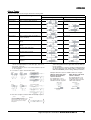
Communications Setting Level
Set the E5AZ/E5EZ/E5CZ communications specifications in the communications setting level. For setting communications parameters, use the
E5AZ/E5EZ/E5CZ panel. The communications parameters and their settings are listed in the following table.
Parameter
Displayed characters
Set (monitor) value
Set value
Communications unit No.
u-no
0 to 99
0.1 to 99
Baud rate
bps
1.2/2.4/4.8/9.6/19.2 (kbps)
1.2/2.4/4.8/9.6/19.2
Data bits
len
7/8 (bit)
7/8 (bit)
Stop bits
sbit
1/2
1/2 (bit)
Parity
prty
None, even, odd
none/euen/odd
Note: The highlighted values indicate default settings.
Before executing communications with the E5AZ/E5EZ/E5CZ, set
the communications unit No., baud rate, etc., through key operations
as described below. As for other operations, refer to relevant Operation Manual.
Set each communications parameter to match those of the communicating personal computer.
1. Press the
key for at least three seconds in the “operation
level.” The level moves to the “initial setting level.”
2. Press the
key for less than one second. The “initial setting
level” moves to the “communications setting level.”
When communicating with the host computer, the unit number must
be set in each Temperature Controller so that the host computer can
identify each Temperature Controller. The number can be set in a
range from 0 to 99 in increments of 1. The default setting is 1. When
using more than one Unit, be careful not to use the same number
twice. Duplicate settings will cause malfunction. This value becomes
valid when the power is turned OFF and ON again.
3. Pressing the
following figure.
4. Press the
key advances the parameters as shown in the
or
keys to change the parameter setups.
Baud rate
Data bits
Data Bits (len)
Use this parameter to change the communications data bit length to
7 bits or 8 bits.
Stop bits
Stop Bits (sbit)
Communications
parity
key is the
Baud Rate (bps)
Use this parameter to set the speed of communications with the host
computer. It can be set to one of the following values; 1.2 (1200 bps),
2.4 (2400 bps), 4.8 (4800 bps), 9.6 (9600 bps), and 19.2
(19200 bps).
This setting becomes valid when the power is turned OFF and ON
again.
Communications
unit No.
Note: On the E5AZ/E5EZ, the
Communications Unit No. (u-no)
Use this parameter to change the communications stop bit to 1 or 2.
key.
Communications parity (prty)
Use this parameter to set the communications parity to None, Even,
or Odd.
Troubleshooting
When an error occurs, an error code will be displayed on the No. 1 display. Check the contents of an error and take appropriate countermeasures.
No.1 display
Contents
Countermeasure
Output status
Control output
Alarm output
Input error (See note.)
Check that the input wiring is correct, that there is no discon- OFF
nection or short-circuit, and that the input type is correct.
(Thermocouple input short-circuits cannot be detected.)
Handled as abnormally high
temperature
A/D converter error
(See note.)
After noting the error, reset the power. If the display does not OFF
change, replacement is necessary. If the error is removed, it
is possible that the original error was caused by noise. Check
that there are no possible sources of noise.
OFF
e111 (E111)
Memory error
HB error (See note.)
Reset the power. If the display does not change, replacement OFF
is necessary. If the error is removed, it is possible that the
OFF
original error was caused by noise. Check that there are no
possible sources of noise.
OFF
h.err (H. Err)
s.err (S. Err)
OFF
Note 1. If the input is within the range for which control is possible but outside the displayable range (−1999 (−199.9) to 9999 (999.9)), (((( will be
displayed if the value is less than −1999 (−199.9), and )))) will be displayed if it is greater than 9999 (999.9). Control output and alarm
output will operate normally for either of these displays. Refer to the relevant User’s Manual for details on the ranges for which control is
possible.
2. These errors are displayed only when the Controller is set to display the present value or the present value and the set value. They are not
displayed in other statuses.
Digital Temperature Controllers
E5AZ/E5EZ/E5CZ
27
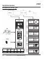
Peripheral Devices
■ Temperature Sensor / SSR
Connection Example with SSR
Temperature Controller
Load
Heater
Voltage output
terminal
(for driving SSR)
Load power
Direct connection possible
3 units
5 units
(E5AZ/
E5EZ)
E5AZ
G3PB (Single-phase): 240 VAC
(15 A, 25 A, 35 A, 45 A)
Rated input voltage:
12 to 24 VDC
ALM1
ALM2
PV
ALM3
Compact and slim models with a
built-in radiator
HB
OUT1
OUT2
SV
STOP
CMW
2 units
4 units
(E5AZ/
E5EZ)
G3PB (Three-phase): 240 VAC/400 VAC
(15 A, 25 A, 35 A, 45 A)
Rated input voltage:
12 to 24 VDC
E5AZ
E52
Simultaneous three-phase control with
a built-in radiator
E5EZ
3 units
5 units
(E5AZ/
E5EZ)
PV
ALM1 ALM2 ALM3
HB
G3PA: 240 VAC (10 A, 20 A, 40 A)
400 VAC (20 A, 30 A)
Rated input voltage:
5 to 24 VDC
Compact and slim models with a
built-in radiator
OUT1 OUT2 STOP CMW
SV
3 units
5 units
(E5AZ/
E5EZ)
E5EZ
ES1B
4 units
for
480-VAC
models
E5CZ
ALM1
PV
ALM2
OUT1 STOP
SV
OUT2
1 unit
2 units
(E5AZ/
E5EZ)
G3NA: 240 VAC (5 A, 10 A, 20 A, 40 A)
480 VAC (10 A, 20 A, 40 A)
Rated input voltage:
5 to 24 VDC
Standard models with screw terminals
G3NE: 240 VAC (5 A, 10 A, 20 A)
Rated input voltage:
12 VDC
E5CZ
Compact and low-cost models
with tab terminals
Number of Connectable SSRs
A: G3PB
(Singlephase)
G3PA
B: G3PB
(Threephase)
C: G3NA
(See note.)
D: G3NE
E: G3NH
E5AZ/EZ
5 units
4 units
5 units
2 units
4 units
E5CZ
3 units
2 units
3 units
1 unit
8 units
Note: 480 VAC models: 4 units
28
Digital Temperature Controllers E5AZ/E5EZ/E5CZ
4 units
8 units
(E5AZ/
E5EZ)
G3NH: 440 VAC (75 A, 150 A)
Rated input voltage:
5 to 24 VDC
For controlling high-power heater
Terms and Conditions of Sale
1. Offer; Acceptance. These terms and conditions (these "Terms") are deemed
part of all quotes, agreements, purchase orders, acknowledgments, price lists,
catalogs, manuals, brochures and other documents, whether electronic or in
writing, relating to the sale of products or services (collectively, the "Products")
by Omron Electronics LLC and its subsidiary companies (“Omron”). Omron
objects to any terms or conditions proposed in Buyer’s purchase order or other
documents which are inconsistent with, or in addition to, these Terms.
2. Prices; Payment Terms. All prices stated are current, subject to change without notice by Omron. Omron reserves the right to increase or decrease prices
on any unshipped portions of outstanding orders. Payments for Products are
due net 30 days unless otherwise stated in the invoice.
3. Discounts. Cash discounts, if any, will apply only on the net amount of invoices
sent to Buyer after deducting transportation charges, taxes and duties, and will
be allowed only if (i) the invoice is paid according to Omron’s payment terms
and (ii) Buyer has no past due amounts.
4. Interest. Omron, at its option, may charge Buyer 1-1/2% interest per month or
the maximum legal rate, whichever is less, on any balance not paid within the
stated terms.
5. Orders. Omron will accept no order less than $200 net billing.
6. Governmental Approvals. Buyer shall be responsible for, and shall bear all
costs involved in, obtaining any government approvals required for the importation or sale of the Products.
7. Taxes. All taxes, duties and other governmental charges (other than general
real property and income taxes), including any interest or penalties thereon,
imposed directly or indirectly on Omron or required to be collected directly or
indirectly by Omron for the manufacture, production, sale, delivery, importation, consumption or use of the Products sold hereunder (including customs
duties and sales, excise, use, turnover and license taxes) shall be charged to
and remitted by Buyer to Omron.
8. Financial. If the financial position of Buyer at any time becomes unsatisfactory
to Omron, Omron reserves the right to stop shipments or require satisfactory
security or payment in advance. If Buyer fails to make payment or otherwise
comply with these Terms or any related agreement, Omron may (without liability and in addition to other remedies) cancel any unshipped portion of Products sold hereunder and stop any Products in transit until Buyer pays all
amounts, including amounts payable hereunder, whether or not then due,
which are owing to it by Buyer. Buyer shall in any event remain liable for all
unpaid accounts.
9. Cancellation; Etc. Orders are not subject to rescheduling or cancellation
unless Buyer indemnifies Omron against all related costs or expenses.
10. Force Majeure. Omron shall not be liable for any delay or failure in delivery
resulting from causes beyond its control, including earthquakes, fires, floods,
strikes or other labor disputes, shortage of labor or materials, accidents to
machinery, acts of sabotage, riots, delay in or lack of transportation or the
requirements of any government authority.
11. Shipping; Delivery. Unless otherwise expressly agreed in writing by Omron:
a. Shipments shall be by a carrier selected by Omron; Omron will not drop ship
except in “break down” situations.
b. Such carrier shall act as the agent of Buyer and delivery to such carrier shall
constitute delivery to Buyer;
c. All sales and shipments of Products shall be FOB shipping point (unless otherwise stated in writing by Omron), at which point title and risk of loss shall
pass from Omron to Buyer; provided that Omron shall retain a security interest in the Products until the full purchase price is paid;
d. Delivery and shipping dates are estimates only; and
e. Omron will package Products as it deems proper for protection against normal handling and extra charges apply to special conditions.
12. Claims. Any claim by Buyer against Omron for shortage or damage to the
Products occurring before delivery to the carrier must be presented in writing
to Omron within 30 days of receipt of shipment and include the original transportation bill signed by the carrier noting that the carrier received the Products
from Omron in the condition claimed.
13. Warranties. (a) Exclusive Warranty. Omron’s exclusive warranty is that the
Products will be free from defects in materials and workmanship for a period of
twelve months from the date of sale by Omron (or such other period expressed
in writing by Omron). Omron disclaims all other warranties, express or implied.
(b) Limitations. OMRON MAKES NO WARRANTY OR REPRESENTATION,
EXPRESS OR IMPLIED, ABOUT NON-INFRINGEMENT, MERCHANTABIL-
14.
15.
16.
17.
18.
ITY OR FITNESS FOR A PARTICULAR PURPOSE OF THE PRODUCTS.
BUYER ACKNOWLEDGES THAT IT ALONE HAS DETERMINED THAT THE
PRODUCTS WILL SUITABLY MEET THE REQUIREMENTS OF THEIR
INTENDED USE. Omron further disclaims all warranties and responsibility of
any type for claims or expenses based on infringement by the Products or otherwise of any intellectual property right. (c) Buyer Remedy. Omron’s sole obligation hereunder shall be, at Omron’s election, to (i) replace (in the form
originally shipped with Buyer responsible for labor charges for removal or
replacement thereof) the non-complying Product, (ii) repair the non-complying
Product, or (iii) repay or credit Buyer an amount equal to the purchase price of
the non-complying Product; provided that in no event shall Omron be responsible for warranty, repair, indemnity or any other claims or expenses regarding
the Products unless Omron’s analysis confirms that the Products were properly handled, stored, installed and maintained and not subject to contamination, abuse, misuse or inappropriate modification. Return of any Products by
Buyer must be approved in writing by Omron before shipment. Omron Companies shall not be liable for the suitability or unsuitability or the results from the
use of Products in combination with any electrical or electronic components,
circuits, system assemblies or any other materials or substances or environments. Any advice, recommendations or information given orally or in writing,
are not to be construed as an amendment or addition to the above warranty.
See http://www.omron247.com or contact your Omron representative for published information.
Limitation on Liability; Etc. OMRON COMPANIES SHALL NOT BE LIABLE
FOR SPECIAL, INDIRECT, INCIDENTAL, OR CONSEQUENTIAL DAMAGES,
LOSS OF PROFITS OR PRODUCTION OR COMMERCIAL LOSS IN ANY
WAY CONNECTED WITH THE PRODUCTS, WHETHER SUCH CLAIM IS
BASED IN CONTRACT, WARRANTY, NEGLIGENCE OR STRICT LIABILITY.
Further, in no event shall liability of Omron Companies exceed the individual
price of the Product on which liability is asserted.
Indemnities. Buyer shall indemnify and hold harmless Omron Companies and
their employees from and against all liabilities, losses, claims, costs and
expenses (including attorney's fees and expenses) related to any claim, investigation, litigation or proceeding (whether or not Omron is a party) which arises
or is alleged to arise from Buyer's acts or omissions under these Terms or in
any way with respect to the Products. Without limiting the foregoing, Buyer (at
its own expense) shall indemnify and hold harmless Omron and defend or settle any action brought against such Companies to the extent based on a claim
that any Product made to Buyer specifications infringed intellectual property
rights of another party.
Property; Confidentiality. Any intellectual property in the Products is the exclusive property of Omron Companies and Buyer shall not attempt to duplicate it
in any way without the written permission of Omron. Notwithstanding any
charges to Buyer for engineering or tooling, all engineering and tooling shall
remain the exclusive property of Omron. All information and materials supplied
by Omron to Buyer relating to the Products are confidential and proprietary,
and Buyer shall limit distribution thereof to its trusted employees and strictly
prevent disclosure to any third party.
Export Controls. Buyer shall comply with all applicable laws, regulations and
licenses regarding (i) export of products or information; (iii) sale of products to
“forbidden” or other proscribed persons; and (ii) disclosure to non-citizens of
regulated technology or information.
Miscellaneous. (a) Waiver. No failure or delay by Omron in exercising any right
and no course of dealing between Buyer and Omron shall operate as a waiver
of rights by Omron. (b) Assignment. Buyer may not assign its rights hereunder
without Omron's written consent. (c) Law. These Terms are governed by the
law of the jurisdiction of the home office of the Omron company from which
Buyer is purchasing the Products (without regard to conflict of law principles). (d) Amendment. These Terms constitute the entire agreement between
Buyer and Omron relating to the Products, and no provision may be changed
or waived unless in writing signed by the parties. (e) Severability. If any provision hereof is rendered ineffective or invalid, such provision shall not invalidate
any other provision. (f) Setoff. Buyer shall have no right to set off any amounts
against the amount owing in respect of this invoice. (g) Definitions. As used
herein, “including” means “including without limitation”; and “Omron Companies” (or similar words) mean Omron Corporation and any direct or indirect
subsidiary or affiliate thereof.
Certain Precautions on Specifications and Use
1. Suitability of Use. Omron Companies shall not be responsible for conformity
with any standards, codes or regulations which apply to the combination of the
Product in the Buyer’s application or use of the Product. At Buyer’s request,
Omron will provide applicable third party certification documents identifying
ratings and limitations of use which apply to the Product. This information by
itself is not sufficient for a complete determination of the suitability of the Product in combination with the end product, machine, system, or other application
or use. Buyer shall be solely responsible for determining appropriateness of
the particular Product with respect to Buyer’s application, product or system.
Buyer shall take application responsibility in all cases but the following is a
non-exhaustive list of applications for which particular attention must be given:
(i) Outdoor use, uses involving potential chemical contamination or electrical
interference, or conditions or uses not described in this document.
(ii) Use in consumer products or any use in significant quantities.
(iii) Energy control systems, combustion systems, railroad systems, aviation
systems, medical equipment, amusement machines, vehicles, safety equipment, and installations subject to separate industry or government regulations.
(iv) Systems, machines and equipment that could present a risk to life or property. Please know and observe all prohibitions of use applicable to this Product.
NEVER USE THE PRODUCT FOR AN APPLICATION INVOLVING SERIOUS
RISK TO LIFE OR PROPERTY OR IN LARGE QUANTITIES WITHOUT
ENSURING THAT THE SYSTEM AS A WHOLE HAS BEEN DESIGNED TO
2.
3.
4.
5.
ADDRESS THE RISKS, AND THAT THE OMRON’S PRODUCT IS PROPERLY RATED AND INSTALLED FOR THE INTENDED USE WITHIN THE
OVERALL EQUIPMENT OR SYSTEM.
Programmable Products. Omron Companies shall not be responsible for the
user’s programming of a programmable Product, or any consequence thereof.
Performance Data. Data presented in Omron Company websites, catalogs
and other materials is provided as a guide for the user in determining suitability and does not constitute a warranty. It may represent the result of Omron’s
test conditions, and the user must correlate it to actual application requirements. Actual performance is subject to the Omron’s Warranty and Limitations
of Liability.
Change in Specifications. Product specifications and accessories may be
changed at any time based on improvements and other reasons. It is our practice to change part numbers when published ratings or features are changed,
or when significant construction changes are made. However, some specifications of the Product may be changed without any notice. When in doubt, special part numbers may be assigned to fix or establish key specifications for
your application. Please consult with your Omron’s representative at any time
to confirm actual specifications of purchased Product.
Errors and Omissions. Information presented by Omron Companies has been
checked and is believed to be accurate; however, no responsibility is assumed
for clerical, typographical or proofreading errors or omissions.
OMRON INDUSTRIAL AUTOMATION • THE AMERICAS HEADQUARTERS
Schaumburg, IL USA • 847.843.7900 • 800.556.6766 • www.omron247.com
OMRON CANADA, INC. • HEAD OFFICE
Toronto, ON, Canada • 416.286.6465 • 866.986.6766 • www.omron247.com
OMRON ARGENTINA • SALES OFFICE
Cono Sur • 54.11.4783.5300
OMRON ELECTRONICS DE MEXICO • HEAD OFFICE
México DF • 52.55.59.01.43.00 • 001.800.556.6766 • [email protected]
OMRON CHILE • SALES OFFICE
Santiago • 56.9.9917.3920
OMRON ELECTRONICS DE MEXICO • SALES OFFICE
Apodaca, N.L. • 52.81.11.56.99.20 • 001.800.556.6766 • [email protected]
OTHER OMRON LATIN AMERICA SALES
54.11.4783.5300
OMRON ELETRÔNICA DO BRASIL LTDA • HEAD OFFICE
São Paulo, SP, Brasil • 55.11.2101.6300 • www.omron.com.br
OMRON EUROpE B.V. • Wegalaan 67-69, NL-2132 JD, Hoofddorp, The Netherlands. • Tel: +31 (0) 23 568 13 00
Fax: +31 (0) 23 568 13 88 • www.industrial.omron.eu
Cat. No. DS-E5CZ
05/08
Note: Specifications are subject to change.
© 2013 Omron Electronics LLC
Printed in U.S.A.