1
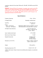
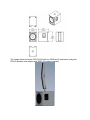
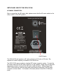
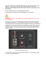
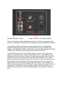
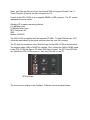
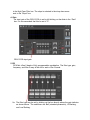
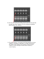
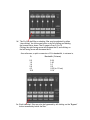
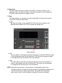
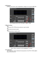
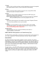
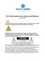
On Point Audio OPA-151SA User Manual
January 2015
The exclamation point within an equilateral triangle is intended to alert the user to
the presence of important operation and maintenance instructions.
The lightening flash with arrowhead symbol within an equilateral triangle is
intended to alert the user to the presence of uninsulated “dangerous voltage”
within the products enclosure that may be of sufficient magnitude to constitute a
risk of electric shock to persons.
The On Point Audio OPA-151SA was designed to provide very high performance sound
reinforcement, very high-output, and low-frequency response, all in a small format
design. The OPA-151SA was designed for use in portable and fixed installation indoor
environments such as night clubs, churches, meeting halls and general live
performance applications. The OPA-151SA features a 15 inch (381 mm) diameter
woofer, Class-D amplifier, digital processing (DSP) and an enclosure design that
provides very high acoustic output with extended low frequency response. The system
also features OPA-Net programming software. The system was designed to work in
conjunction with the On Point Audio OPALine-82, OPA-8NP, OPA-28NP and the OPA-5
systems.
WARNING: Only the OPALine-82 is designed to be speaker pole mounted on the OPA151SA! Use the PSA-82 pole adaptor and bracket when speaker pole mounting the
OPALine-82 on the OPA-151SA. Information about the PSA-82 can be found on the On
Point Audio web site. The OPA-8NP, OPA-28NP and OPA-5 are NOT designed to be
speaker pole mounted on the OPA-151SA!
Specifications
Frequency Response:
Coverage Pattern:
Input/Thru:
Power:
Peak - Total System:
Continuous- Total System:
AC Mains Power (Universal):
40 Hz – 150 Hz
Essentially omnidirectional
3-Pin XLR-type
(Pin 2 +)
2,000 Watts (1000 W to Sub and 1000W to top box)
1,000 Watts (500 W to Sub and 500W to top box)
115 V AC to 230 V AC
Min 85V AC – Max 265 V AC
(50 Hz – 60 Hz)
Input to achieve rated output:
0.774 V RMS
Max Acoustic Output (Peak):
131 dB*
Supplied Accessories:
Dimensions (H X W X D):
Weight:
Operating temperature (C/F)
AC Mains Cable
RS 485 Cable
OPA-Net software
530mm x 420mm x 598.1mm
20.87” x 16.54” x 23.55”
30.8 kg (68 lb.)
0C-43C / 32F- 110F
* NOTE: Max Acoustic Output is based on smoothed system response, not peak driver
response.
The image below shows the OPA-151SA with two OPALine-82 enclosures (using the
PSA-82 speaker pole adaptor and TBEC-82 coupling bracket).
Read all of the instructions included in this manual
Copies of this manual should be retained by both the system installer and the end user.
This manual must be read and understood and all warnings must be followed.
Follow all instructions to ensure optimal product performance.
The OPA-151SA is a convection-cooled device and it requires at least 7 inches (178
mm) of clearance behind the enclosure, to allow the heat sink to adequately cool the
internal electronics.
DO NOT INSTALL NEAR ANY HEAT SOURCES!
Use only the supplied AC Mains connector.
Protect the AC Mains power cord from being walked on or otherwise damaged and
inspect for damaged connections and damaged insulation
There are NO user serviceable parts inside the enclosure. DO NOT REMOVE THE
AMPLIFIER MODULE! (See Service section for details or contact One Systems)
FCC STATEMENT
The OPA-151SA has been tested and is compliant with the limits for Class B digital
devices, per Part 15 of the FCC rules. Test data is available from On Point Audio.
INTRODUCTION
Thank you for purchasing the On Point Audio OPA-151SA and for your faith in us and
our products. The OPA-151SA will provide you many years of useful service with proper
use and care. Please read this manual completely and become familiar with the design
and operation of this advanced active subwoofer system.
CONTENTS
The OPA-151SA system is shipped in one carton. The contents of the carton are as
follows:
OPA-151SA System
1. One OPA-151SA that includes a Class-D digital power amplifier system with onboard
Digital Signal Processing (DSP).
2. RS 485 cable for remote programming of selected features of the OPA-151SA DSP
based pre amplifier.
3. OPA-151SA AC mains cables (120VAC or 230VAC)
4. OPA-Net installation CD ROM
WHEN USING THE PSA -82 POLE ADAPTOR WITH THE OPA 151SA, THE OPA151SA ENCLOSURE MUST BE PLACED ON A LEVEL SURFACE. DO NOT USE
THE POLE IF THE GROUND’S SURFACE IS NOT LEVEL!
FEATURES AND APPLICATIONS
The OPA-151SA is a professional product and is designed to be used with a highquality mixing console. The OPA-151SA includes factory preset crossover and
equalization functions. Additional equalization and delay settings are user
programmable via a PC and the supplied RS 485 cable. Any additional equalization
functions attempted in via a mixing console or outboard EQ device should be very
carefully applied in order to prevent input overload and signal clipping in the OPA151SA pre amp!
The OPA-151SA features an onboard digital signal processor (DSP) that performs
analog to digital conversion, equalization, high-order crossover, delay and system
dynamics processing. The system’s dynamics processing consists of a
compressor/limiter function designed to provide both ultra-fast threshold system
protection and maximized system dynamics.
SETUP AND USE OF THE OPA-151SA
AC MAINS CONNECTION
Prior to connecting the AC mains cable, please ensure that the AC mains switch on the
OPA-151SA is in the OFF position.
On/Off Switch
The OPA-151SA will operate on AC mains voltages of 115 volts to 230 volts. The
required AC mains frequency is between 50 Hz and 60 Hz.
The OPA-151SA uses an industry standard IEC mains connector system. To mate the
AC mains cable with the AC mains connector on the amplifier, simply align the plug with
the panel’s connector and press the AC mains cable into place. Always support the
OPA-151SA enclosure with one hand while performing this operation. The AC mains
connector is shown below. It is located on the lower portion of the OPA-151SA input
panel.
AC Mains panel connector
To disconnect the cable end of the AC mains connector from the OPA-151SA, simply
pull the cable end away from the enclosure. Make certain to support the OPA-151SA
enclosure with one hand while performing this operation. Pull from the molded end of
the AC mains cable’s plug, not the cable itself.
NOTE: ALWAYS turn off the AC mains power BEFORE disconnecting the AC mains
cable from the OPA-151SA amplifier module!
DO NOT CONNECT THE AC MAINS END OF THE AC MAINS CABLE IN AN AREA
THAT IS WET OR SUBJECT TO CONDENSATION OR DAMP CONDITIONS!
Once the AC mains cable is securely connected to both the amplifier and AC mains
supply, the OPA-151SA enclosure may be turned on. It is good practice is to make
certain that the audio levels on the mixer’s output (or other source output) are reduced
or muted prior to applying power to the OPA-151SA.
NOTE: When power is applied to the OPA-151SA and the unit is turned on there is
approximately a 5 to 15 second delay before the pilot light illuminates.
Pilot Light
NOTE: If the pilot light does not illuminate within 30 seconds the unit may be in a
FAULT CONDITION. If this occurs, the unit should be returned to On Point Audio for
evaluation.
THERE ARE NO USER-SERVICABLE PARTS INSIDE. DO NOT REMOVE THE
AMPLIFIER MODULE!
AUDIO CONNECTIONS
The OPA-151SA includes both a male and female XLR-type connectors. Any standard
XLR-type cable end connectors may be used.
The image below illustrates the top portion of the OPA-151SA input plate. Both the
audio input and audio high-pass output connectors are shown.
Parallel Output
Input
The Line Input connector should be used for the MAIN full-range audio input signal.
The Parallel output is used to parallel the input signal to other powered loudspeaker
enclosures. All full range input material is high pass filtered in the system DSP. The low
frequency material is routed to the internal high power 15 inch woofer. The high
frequency material is routed to the Speaker Level High Pass Output found near the AC
mains switch. This output directs all signal content above the program selected high
pass filter frequency to the selected top enclosure (OPALine-28, OPA-5, OPA-8NP or
OPA-28NP).
.
Any professional-grade XLR to XLR cable may be used for the line level input wiring. In
all cases, pin 2 on the XLR connector is the positive terminal.
The Speaker Level High Pass Output requires a standard Neutrik Speakon connector.
The other end of the Speaker Level High Pass Output cable must be stripped and
terminated to allow for wiring to the approved On Point Audio “top box” loudspeaker.
Presets 1 thru 4 are factory programmed for the OPALine-28, OPA-5, OPA-8NP or
OPA-28NP).
The Speaker Level High Pass Output is shown below. The speaker cable is NOT
supplied by On Point Audio. On Point Audio recommends wire gauge between AWG 16
and AWG 12, depending on the length of the wire between the OPA-151SA enclosure
and the top box enclosure. A 4 pin Speakon is required for the “amplifier” output side of
the speaker cable. The “speaker” side will be stripped bare wire or stripped bare wire
with terminals suitable for the loudspeaker input barrier strip.
Speaker Level High Pass Output
An audio input level of 0.774 V RMS will drive the OPA-151SA amplifier to full power.
Because each preset offers different equalization this 0.774 Vrms (0 dBu) level is simply
a mid-band reference.
WARNING
DO NOT PLACE ANY OTHER LOUDSPEAKERS, EXCEPT FOR THE APPROVED ON
POINT AUDIO MODELS, ON THE OPA-151SA POLE. ONLY THE OPALINE-82,
MOUNTED WITH THE PSA-82 BRACKET IS APPROVED!
USE ONLY THE POLE(s) SUPPLIED AND REFER TO THE PSA-82 INSTALLATION
MANUAL. THIS MANUAL MUST BE READ AND UNDERSTOOD PRIOR TO
MOUNTING THE OPALINE-82 AND PSA-82 ONTO THE OPA-151SA SUB WOOFER
ENCLOSURE.
DO NOT SUBSTITUTE ANY OTHER MOUNTING POLES.
ALL ASSOCIATED RIGGING IS THE RESPONSIBILITY OF OTHERS.
WARNING: DO NOT POLE MOUNT ANY OTHER LOUDSPEAKERS ON TOP OF
THE OPALINE-82!
The OPA-151SA features user settable input level gain. Caution should be exercised
when setting this gain level. It is recommended that the gain be set to the 0dB point
and that all system gain be controlled via the mixing desk. If excessive output levels are
presented to the input of the OPA-151SA, it is possible to overload (clip) the input and
produce distortion. If distortion is heard, the OPA-151SA input gain may be reduced, or
the mixer level gain at the output of the mixing desk may be reduced to eliminate the
system overload.
OPA-151SA system Input Gain
The OPA-151SA offers processor dynamics limit indications, as well as signal present
and signal input clipping indication.
Processor Dynamics Limiting
Signal Present and Input Signal Clipping
Processor Dynamics Limiting will indicate the status of the factory programmed peak
limiter and compressors. When this LED is illuminated the input gain should be reduced.
The Signal/Clip indication will illuminate when signal is present. If the Signal/Clip
indicator is blinking the input signal to the OPA-151SA is too high, indicating input
clipping. If the Signal/Clip indicator is blinking then the audio signal supplied to the OPA151SA must be reduced (ie mixer output or other source output level)
The OPA-151SA also offers 7 Pre-Set EQ programs. Presets 1 thru 4 are factory
defined for selected On Point Audio products. Presets 5 thru 7 are available for user
defined presets via OPA-Net pc software. Pre Set 8 is low level pink noise. Preset 8 is
included in case the knob is removed from the PRE-SET EQ selector. The selector
shaft can be easily rotated until the low level noise is heard. Once the low level noise is
heard the knob can be re-attached with the know selector “arrow” set to position 8.
Presets 1 thru 4 are set at the factory and cannot be modified. As an example, if the
OPA-151SA is being used with the OPALine-82, Preset 4 should be opened. Then any
modifications to equalization or delay settings required for the venue acoustics or
desired voicing may be made and the resultant program can be saved into Presets 5
thru 7.
The preset list is found immediately below the OPA-151SA input section as shown
below.
The OPA-151SA Preset list
USING THE OPA-151SA PRE AMP AND OPA-NET
COMPUTER CONTROLLED SOFTWARE
The OPA-151SA features a high performance digital signal processor (DSP). The
operating software allows a user to program selected features of the DSP. These
features include gain, equalization and delay. The delay functions are available on both
the sub channel and the high pass output channel. This allows delay to be set based on
the physical location of the OPA-151SA subwoofer enclosure relative to the top
enclosure (OPALine-82, OPA-5, OPA-28NP, and OPA-8NP).
Programs (Presets) 1 thru 4 are factory defined and cannot be overwritten. The
recommended process to define new settings is to recall one of the 4 factory presets,
based on the specific top box being used, and make the required modifications to EQ,
Delay, and Gain and then store into the onboard DSP in Program (Preset) 5 thru 7.
These Programs (Presets) can also be saved to a PC.
Control of the OPA-151SA is via a supplied RS485 to USB connector. The PC system
requirements are as follows:
Windows XP or newer operating software
512 MB Ram (min)
20 MB hard drive (min)
NET Framework 4.0
USB
Monitor 1024x768
The OPA-151SA is supplied with the required CD ROM. To load OPA-Net onto a PC,
follow the steps shown in the popup windows when the .exe file is running.
The PC must be connected to the OPA-Net input on the OPA-151SA as shown below.
The required cable (USB to RS485) is supplied. First, connect the USB to RS485 cable
to the OPA-151SA and then to PC where OPA-Net is loaded. Do NOT start OPA-Net
yet. Switch the OPA-151SA power on, then start OPA-Net on the PC.
OPA-Net input
The first screen to display is the Configure ID Device screen as shown below.
The simplest selection is to highlight “with one device” as shown above.
Now click the “Search COM button on the window (shown above). The Search function
will determine which COM port the USB connector is plugged in to and set the com port
for that address automatically.
For typical applications where only one OPA-151SA is being used the ID Select will be
the value “1”.
After the OPA-Net communications have been established the next screen that will
appear is shown below. The ID List will populate with the devices that the OPA-Net
software detects. To access a device simply double click on the desired device
The main OPA-Net screen will now appear as shown below. All of the allowable
parameters are now available for modification, recall, saving or monitoring.
The set up process should be as follows:
1. Source selection
Select either the analog input or noise generator. Note: Ensure that the noise
generator level is fully attenuated prior to selecting this source. The normal
selection is the analog input. The noise generator may be used for system eq.
Source selection
2. DLF selection
DLF is a dynamic loudness filter. The dynamic loudness compensation contour
is set with peak frequencies at 50Hz and 12kHz. When the DLF is activated
there is a maximum low frequency boost of 9.3dB and a maximum high
frequency boost of 5dB. At -16dBu the gain of the low frequency boost and
high frequency boost begins reducing. As the input levels increase above
-16dBu the gain progressively reduces. The DLF function is 1.6dB low
frequency boost at 0dBu input level and the high frequency boost at 0dBu
is 0.6dB. The DLF is basically out of circuit at +2dBu input level. Care should be
taken when using the DLF as the combination of DLF boost as well as additional
DSP based EQ and outboard EQ (ie mixer or graphic EQ)
can produce system clipping at high input levels!
DLF Selection
3. High Pass Filter
A selectable High Pass Filter may be inserted into the signal path if desired.
NOTE: Presets 1 thru 4 already have high order (24dB/Oct Butterworth) filters
in the signal path. The addition of this High Pass Filter will likely not be
necessary but is available if additional rapid attenuation is required.
The high pass filter frequency is set by left clicking on the “Frequency” section
in the High Pass Filter box. The slope is selected in the drop down menu
next to the “Slope” box.
4. Gain
The input gain of the OPA-151SA is set by left clicking on the slider in the “Gain”
box. It is recommended that this be set to “0”.
OPA-151SA input gain
5. EQ
OPA-Net offers 5 bands of fully programmable equalization. The filter type, gain,
frequency, and filter Q may all be set for each of the 5 bands.
5a. The filter type may be set by clicking on the box directly above the gain indicator
as shown above. The selections are: Bell (standard parametric), Hi Shelving,
and Low Shelving.
5b. The filter gain may be set by holding the left mouse click down and then
the slider up or down. The gain, in dB, will be displayed immediately
above the slider in the “Gain box”.
5c. The center frequency, in the case of a bell filter (parametric) or corner
frequency, in the case of a High Shelf or Low Shelf, may be set by
left clicking on the Frequency, back spacing to erase the current
frequency, and then entering the desired center frequency or
corner frequency.
5d. The Q of the bell filter or shelving filter may be adjusted by either
“step clicking” the left mouse button or by left clicking and holding
the mouse button down. The Q range is from 0.5 to 10
Clicking the right facing arrow will increase the Q, and clicking on
the left facing arrow will decrease the Q.
As a reference, a quick conversion of Q to bandwidth, in octaves is;
Q
0.5
1.0
1.4
2.9
4.3
10.0
Bandwidth (Octaves)
2.54
1.40
1.0
0.5
0.33 (ie 1/3 oct)
0.14
5e. Each individual filter may also be bypassed by left clicking on the “Bypass”
button immediately below the filter.
6. Delay Units
The Delay Units can be set in either time (mSec) or distance (meters). The
maximum delay is 9 mSec (3 meters). The delay increments can be adjusted in
0.01mSec steps using the Fine adjust function.
7. Delay
The Delay function can be used to provide signal delay for three basic sections
of the OPA-151SA as noted below:
a. Input
This allows the delay of the overall OPA-151SA and top box system to be
adjusted when multiple OPA-151SA systems are being used.
Delay functions
b. Low
The Low delay is used when the physical placement of the OPA-151SA is closer
to the listening area then the top enclosures. This allows the subwoofer signal
to be aligned with the arrival time of the top enclosure.
c. High
The High delay is used when the physical placement of the top enclosure is
closer to the listening area then the subwoofer. This allows the top enclosure
to be aligned with the arrival time of the subwoofer.
NOTE: When the sub enclosure or top enclosure is substantially closer to the
listening area then it is likely that sound pressure level differences between the
sub and top enclosure will be experienced. Broad band EQ (essentially
gain) may be used, as well as delay to optimize the acoustic response.
8. EQ Bypass
Activating this function sets all equalization settings to a unity gain (0dB) level.
The EQ bypass will set ALL EQ bands to a gain of 0dB.
9. Mute functions
Input
The entire OPA-151SA and top enclosure may be muted
Low
The subwoofer may be muted
High
The top enclosure may be muted
When a Mute is selected it will be highlighted in red colo
10. Temperature
The Temperature section indicates the temperature of the OPA-151SA amplifier
output section heat sink.
11. Load
Clicking on the Load button will open a window that allows a program to be imported
from a saved location in the PC to the on board OPA-151SA memory.
12. Save
Clicking on the Save button will allow a program in the on board OPA-151SA
memory to be saved to a location on the PC
13. Store
This function allows modified programs to be stored in the DSP memory by
selecting the program name and position.
NOTE: Program (Preset) positions 1 thru 4 are locked and cannot be “overwritten”
The only allowable positions to store new programs are 5 thru 7.
14. Recall
This function allows programs to be recalled to active status. Programs (Presets)
1 thru 4 are factory defined and can only be recalled.
15. Setup
The Setup mode should NOT be used for the OPA-151SA or ANY OTHER
On Point Audio products. The selected mode should be “2 way mode” ONLY!
Do not activate Bridge Mode configuration!
16. Name Device
This feature allows the user to name the OPA-Net preset used in a
specific installation or environment.
USING THE OPA-151SA (Application and Trouble Shooting Tips)
The OPA-151SA is a high-quality professional sound reinforcement system designed for
use in indoor applications. Some basic precautions will insure long-term reliability.
EQUALIZATION
The OPA-151SA has all the required equalization functions included in the internal
Digital Signal Processor (DSP). All equalization and gain functions have been optimized
for flat frequency response and maximized system dynamics. Care should be taken to
insure that external gain and EQ, user settable gain and EQ, and fixed internal EQ and
gain to do not sum to produce signal clipping. If clipping, or distorted sound, is heard
then gain/eq must be reduced.
The gain function on the OPA-151SA should be set to ensure the desired acoustic
response and output of the system. Care should be taken when setting the gain of the
OPA-151SA and the gain of the mixing console to insure that the gain of the external
mixing console is not turned too high and induce clipping and overload in the OPA151SA.
The mixing console should be capable of providing sufficient output signal levels to
supply the necessary voltage levels to drive the OPA-151SA to full power and still
insure adequate headroom in the mixing console.
The OPA-151SA will produce full power with a 0.774 V RMS (0dBu) input signal.
If additional equalization is required, care should be taken to avoid excessive EQ in any
frequency band, but particularly at low frequencies. Excessive equalization can
produce “band selective” clipping and distortion. All EQ boost levels should be
monitored if system distortion is present.
DISTORTED SOUND
When input levels to the OPA-151SA exceed 0.774 Vrms (0dBu), the internal dynamics
processing functions automatically engage to provide system protection. However, it is
still possible to “overdrive” the input section of the subwoofer system. If distorted sound
is present, the following steps should be taken:
1. Verify that the mixer’s output is not clipping or overloaded. If the output metering
of the mixing console is continuously in the “red”, then the output level should be
reduced (occasional “red” indications are usually fine but are dependent on the
mixing console’s output capability).
2. Verify that excessive equalization is not present anywhere in the signal chain.
3. Verify that AC mains levels are within the required range.
Voltage measurements on the AC Mains should be performed by a licensed electrician
or individual trained in making high-voltage measurements.
NO SOUND
1. Verify that signal is present on the input of the OPA-151SA.
2. Verify that there is AC Mains voltage on the AC Mains input to the OPA-151SA
3. If AC Mains voltage is present, verify that the OPA-151SA’s fuse is not blown.
NOTE: IF THE FUSE IS BLOWN, REPLACE ONLY WITH THE SAME TYPE OF FUSE.
THIS FUSE TYPE IS NOTED ON THE INPUT PANEL NEAR THE FUSE HOLDER.
THE LOCATION OF THE FUSE HOLDER IS SHOWN BELOW. NOTE: This fuse type
is 6.3AH250VP.
FUSE HOLDER (located inside the IEC AC mains connector)
PRODUCT SERVICE
There are NO user-serviceable parts inside the OPA-151SA enclosure or amplifier.
The OPA-151SA amplifier module MUST be serviced by a company authorized by On
Point Audio or One Systems, Inc.
Replacement of Components
REPLACEMENT OF COMPONENTS MUST BE PERFORMED BY A QUALIFIED
TECHNICIAN OR ONE KNOWLEDGABLE IN THE REPLACEMENT OF
TRANSDUCER COMPONENTS!
DO NOT ATTEMPT ANY REPAIRS UNLESS THE OPA-151SA AMPLIFIER HAS
BEEN DISCONNECTED FROM THE AC MAINS SOURCE!
In the event of woofer failure the woofer may be accessed by removing the front grille
and then removing the woofer. This should be done by a qualified technician or
contractor. There is no need to remove the amplifier’s panel in the event of a woofer
failure.
Please note the wiring polarity and observe the same polarity when replacing the
woofer.
The OPA-151SA has been tested to the following standards:
EN55013: 2013
EN55020: 2007 + A11:2011
EN61000-3-2:2006 + A2:2009
EN61000-3-3:2013
EN60065:2002 + A1:2006 + A11:2008 + A2:2010 + A12:2011
© 2015 On Point Audio
One Systems, Inc.
Nashville, TN 37215 U.S.A.
www.onpointaudio.com
www.onesystems.com