1
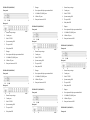
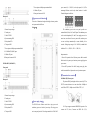
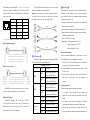
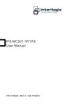
【Summarize】 【Feature】 IES1024 series is a Plug-and-play unmanaged industrial Ethernet High performance network exchange technology switch. The IES1024 industrial Ethernet switches consists of 24 Support IEEE802.3, IEEE802.3u, IEEE 802.3x Ethernet ports. The IES1024-2F industrial Ethernet switches Support 8K MAC address consists of 22 Ethernet ports and 2 Fiber ports. The IES1024-4F Support 12.8Gbps backboard bandwidth industrial Ethernet switches consists of 20 Ethernet ports and 4 10/100BaseT(X)(RJ45) Fiber ports. The IES1024-8F industrial Ethernet switches consists Store and Forward switching process type of 16 Ethernet ports and 8 Fiber ports. The IES1024-12F Plug-and-play, auto MDI/MDI-X connection industrial Ethernet switches consists of 12 Ethernet ports and 12 Support auto negotiation speed, F/H duplex mode, and auto Fiber ports. The IES1024-16F industrial Ethernet switches send data control consists of 8 Ethernet ports and 16 Fiber ports that provide an Reliable Industrial grade design economical solution for your industrial Ethernet connection. The Industrial grade 4 design, -40-75℃work temperature IES1024 series IES1024-20F industrial Ethernet switches consists of 4 Ethernet No fan deign ports and 20 Fiber ports. The IES1024-24F consists of 24 Fiber IP30 protection grade Industrial Ethernet switch ports that provide an economical solution for your industrial 19 inch rack mounting User manual Ethernet connection. The IES1024 series switches have an operating temperature range of -40 to 75°C, and are designed with low consumption and 【Panel layout】 IES1024-P (100/240VAC) Front panel without fan. The rugged hardware design makes the IES1024 perfect for ensuring that your Ethernet equipment can withstand the rigors of industrial applications. Rear panel 【Packing list】 Please check the packaging and accessories by your first using. Shenzhen 3onedata Technology Co., Ltd Tel: +86-755-26702668 Fax: +86-755-26703485 www.3onedata.com 1. Restore factory settings Industrial Ethernet switch ⅹ 1 2. Console port User manual ⅹ 1 3. Link/ACT LED Certificate of quality ⅹ 1 4. Systems running LED Warranty card ⅹ 1 5. The power LED Power adapter ⅹ 1 6. Relay alarm LED Please inform us or our distributor if your equipments have 7. Hangers been damaged or lost any accessories, we will try our best to 8. Power input and Relay output terminal block satisfy you. 9. 10/100BaseT(X) (RJ45) ports 10. Rear panel connector LED IES1024-2F-P (100/240VAC) 7. Hangers 1. Restore factory settings Front panel 8. Power input and Relay output terminal block 2. Console port 9. 10/100BaseT(X) (RJ45) ports 3. Link/ACT LED 10. 100Base-FX ports 4. Systems running LED 11. Rear panel connector LED 5. The power LED 6. Relay alarm LED IES1024-8F-P (100/240VAC) 7. Hangers Front panel 8. Power input and Relay output terminal block Rear panel 1. Restore factory settings 9. 10/100BaseT(X) (RJ45) ports 2. Console port 10. 100Base-FX ports 3. Link/ACT LED 11. Rear panel connector LED 4. Systems running LED 5. The power LED IES1024-16F-P (100/240VAC) 6. Relay alarm LED Front panel 7. Hangers 1. Restore factory settings 8. Power input and Relay output terminal block 2. Console port 9. 10/100BaseT(X) (RJ45) ports 3. Link/ACT LED 10. 100Base-FX ports 4. Systems running LED 11. Rear panel connector LED 5. The power LED 6. Relay alarm LED IES1024-4F-P (100/240VAC) 7. Hangers 1. Restore factory settings Front panel 8. Power input and Relay output terminal block 2. Console port 9. 10/100BaseT(X) (RJ45) ports 3. Link/ACT LED 10. 100Base-FX ports 4. Systems running LED 11. Rear panel connector LED 5. The power LED 6. Relay alarm LED IES1024-12F-P (100/240VAC) 7. Hangers Front panel 8. Power input and Relay output terminal block Rear panel Rear panel Rear panel 1. Restore factory settings 9. 10/100BaseT(X) (RJ45) ports 2. Console port 10. 100Base-FX ports 3. Link/ACT LED 11. Rear panel connector LED 4. Systems running LED 5. The power LED IES1024-20F-P (100/240VAC) 6. Relay alarm LED Front panel Rear panel Rear panel 7. Power input and Relay output terminal block power entered (L/+, GND, N/-) and relay output (R+, R-).The 8. 100Base-FX ports unmanaged Ethernet switch relay alarm function is invalid. 9. Rear panel connector LED Terminal diagram is as follows: 【Appearance and dimension】 This series of dimensions length width height, between product series port number is different. 1. Restore factory settings Unit(mm) The redundancy power series rear panel provides two 2. Console port terminal blocks (5 bits) for P1 and P2 input. The redundant power 3. Link/ACT LED can be used independently. P1 and P2 can supply power at the 4. Systems running LED same time, once either of these two powers fails, another power 5. Relay alarm LED can acts as backup automatically to ensure reliability of the 6. The power LED network. Voltage input range is 100~240VAC (terminal block 7. Power input and Relay output terminal block defined as P1: L/+, GND, N/-; P2: L/+, GND, N/- ). 8. 10/100BaseT(X) (RJ45) ports 9. 100Base-FX ports Important notice: 10. Rear panel connector LED 1. Power ON operation: first of all, insert power cable’s terminal block into device’s power port, then insert power supply plug into IES1024-24F-P (100/240VAC) power source Front panel 2. Power OFF operation: First off all, unpin power plug, then strike the terminal block, please take care of operation sequence. 【Communication connector】 10/100BaseT(X) Ethernet port Rear panel The pinout of RJ45 port display as below, connect by UTP or STP. The connect distance is no more than 100m. 100Mbps is used 120Ω of UTP 5; 10Mbps is used 120Ω of UTP 3, 4, 5. 1. Restore factory settings 2. Console port 3. Link/ACT LED 【Power supply input】 4. Systems running LED The IES1024 series Ethernet switch have singe power and 5. Relay alarm LED redundancy power two kinds of power input. The singe power 6. The power LED series rear panel provides 5 bit wiring terminal for AC100~240V RJ 45 port support automatic MDI/MDI-X operation. Can connect the PC, Server, Converter and HUB .Pin 1,2,3,6 Corresponding connections in MDI. 1→3, 2→6, 3→1, 6→2 are The optical fiber connection supports the line to instruct 【Installation】 used as cross wiring in the MDI-X port of Converter and HUB. enhance the reliability of network effectively. Before installation, confirm that the work environment meet the 10Base-T/100Base-TX are used in MDI/MDI-X, the define of Pin Suppose: If you make your own cable, we suggest labeling the installation require, including the power needs and abundant in the table as below. two sides of the same line with the same letter (A-to-A and space. Whether it is close to the connection equipment and other B-to-B, shown as below, or A1-to-A2 and B1-to-B2). equipments are prepared or not. 1 8 NO. MDI signal MDI-X signal 1 TX+ RX+ 2 TX- RX- 3 RX+ TX+ 2. Examine the cables and plugs that installation requirements. 6 RX- TX- 3. Examine whether the cables be seemly or not (less than 100m) 4, 5, 7, 8 — — 1. Avoid in the sunshine, keep away from the heat fountainhead or the area where in intense EMI. according to reasonable scheme. 4. Power: 100-240VAC power input Note:“TX±”Transmit Data±,“RX±”Receive Data±,“—”Not Use. 5. Environment:working temperature: -40~75℃ MDI (straight-through cable) Storage Temperature: -40~85℃ Relative humidity 5%~95% Rack mount installation 【LED Indicator】 In most of industrial application, it is convenience to use rack LED indictor light on the front panel of product, the function of each LED is described in the table as below. System Indication LED MDI-X (Cross over cable) LED State ON PWR1 OFF MDI/MDI-X auto connection makes switch easy to use for customers without considering the type of network cable. 100Base-FX Fiber port 100Base-FX full-duplex SM or MM port, SC/ST/FC ON PWR2 OFF RUN type .The fiber port must be used in pair, TX (transmit) port connect remote switch’s RX (receive) port; RX (receive) port Link/ACT connect remote switch’s TX (transmit) port. (1~24) Description Power is being supplied to power input PWR1 input mount installation, the step of installation is as follows: 1. Check if have rack mount installation tools and components (The package provided parts of components) 2. Check installation place strong or not, have the place to install the device or not. 3. Put the device into rack, aim at the screw hole of device and Power is not being supplied rack, fixed it in strong screw. Easy and convenience to to power input PWR1 input operation. Power is being supplied to power input PWR2 input Power is not being supplied to power input PWR2 input ON/OFF System is not running well Blinking System is running well ON Port connection is active Blinking Data transmitted OFF Port connection is not active Wiring Requirements Cable laying need to meet the following requirements, 1. It is needed to check whether the type, quantity and specification of cable match the requirement before cable laying; 2. It is needed to check the cable is damaged or not, factory records and quality assurance booklet before cable laying; 3. The required cable specification, quantity, direction and laying position need to match construction requirements, and cable length depends on actual position; 4. All the cable cannot have break-down and terminal in the single mode(20/40/60/80Km optional), multi mode Full load consumption: 17.2W (2Km), wavelength: 1310nm, 1550nm IES1024-16F-P (100/240VDC): Console port: Retain Unload consumption: 17.3W 5. Cables should be straight in the hallways and turning; Alarm port: Retain Full load consumption: 19.8W 6. Cable should be straight in the groove, and cannot beyond the Transfer distance IES1024-20F-P (100/240VDC): Twisted cable: 100M( standard CAT5/CAT5e cable) Unload consumption: 18.8W Multi-mode: 1310nm, 2/5Km Full load consumption: 20.7W middle; groove in case of holding back the inlet and outlet holes. Cables should be banded and fixed when they are out of the groove; 7. User cable should be separated from the power lines. Cables, power lines and grounding lines cannot be overlapped and mixed when they are in the same groove road. When cable is too long, it cannot hold down other cable, but structure in the middle of alignment rack; 8. Pigtail cannot be tied and swerved as less as possible. Single-mode: 1310nm, 20/40/60Km 1550nm, 80/100/120Km IES1024-24F-P (100/240VAC): Unload consumption: 21.7W LED indicator Full load consumption: 22.9W Run indicator: Run Working environment Interface indicator: Link (1~24) Power supply indicator: PWR1 (PWR2) Working temperature: -40~75℃ Storage temperature:-40~85℃ Swerving radius cannot be too small (small swerving causes Power supply Relative Humidity: 5%~95% (no condensation) terrible loss of link). Its banding should be moderate, not too Input voltage: 100~240VAC Mechanical Structure tight, and should be separated from other cables; Type of input: 3 bit terminal block 9. It should have corresponding simple signal at both sides of the cable for maintaining. 【Specification】 Technology Standard: Support IEEE802.3, IEEE802.3u, IEEE 802.3x Flow control: IEEE802.3x flow control, back press flow control Exchange attribute 100M forward speed: 148810pps Transmit mode: store and forward System exchange bandwidth: 12.8G MAC address table: 8K Memory: 4M Interface Electric port: 10Base-T/100Base-TX auto speed control, Half/full duplex and MDI/MDI-X auto detect 100M optic fiber port: 100Base-FX, SC/ST/FC connector, support Overload Current Protection: 1.2A Shell: IP30 protect grade, metal shell Installation: 19” 1U rack Consumption Size(W×H×D): 441.6mm×45mm×208.9mm IES1024-P(100/240VDC): Industry Standard Unload consumption: 6.9W Full load consumption: 9.4W EMI: FCC Part 15, CISPR (EN55022) class A EMS: EN61000-4-2 (ESD), Leve 4 IES1024-2F-P (100/240VDC): EN61000-4-3 (RS), Level 3 Unload consumption: 8.2W EN61000-4-4 (EFT), Level 4 Full load consumption: 10.7W EN61000-4-5 (Surge), Level 4 IES1024-4F-P (100/240VAC): EN61000-4-6 (CS), Level 3 Unload consumption: 9.5W EN61000-4-8, Level 5 Full load consumption: 12.0W IES1024-8F-P (100/240VDC): Unload consumption: 12.1W Shock: IEC 60068-2-27 Free fall: IEC 60068-2-32 Vibration: IEC 60068-2-6 Full load consumption: 14.6W Certification IES1024-12F-P (100/240VAC): CE, FCC, RoHS, UL508 (Pending) Unload consumption: 14.7W Warranty: 5 years