1
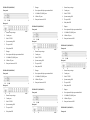
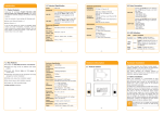
Rear panel
7. Power input and Relay output terminal block
power entered (L/+, GND, N/-) and relay output (R+, R-).The
8. 100Base-FX ports
unmanaged Ethernet switch relay alarm function is invalid.
9. Rear panel connector LED
Terminal diagram is as follows:
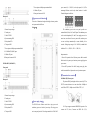
【Appearance and dimension】
This series of dimensions length width height, between product
series port number is different.
1. Restore factory settings
Unit(mm)
The redundancy power series rear panel provides two
2. Console port
terminal blocks (5 bits) for P1 and P2 input. The redundant power
3. Link/ACT LED
can be used independently. P1 and P2 can supply power at the
4. Systems running LED
same time, once either of these two powers fails, another power
5. Relay alarm LED
can acts as backup automatically to ensure reliability of the
6. The power LED
network. Voltage input range is 100~240VAC (terminal block
7. Power input and Relay output terminal block
defined as P1: L/+, GND, N/-; P2: L/+, GND, N/- ).
8. 10/100BaseT(X) (RJ45) ports
9. 100Base-FX ports
Important notice:
10. Rear panel connector LED
1. Power ON operation: first of all, insert power cable’s terminal
block into device’s power port, then insert power supply plug into
IES1024-24F-P (100/240VAC)
power source
Front panel
2. Power OFF operation: First off all, unpin power plug, then
strike the terminal block, please take care of operation sequence.
【Communication connector】
10/100BaseT(X) Ethernet port
Rear panel
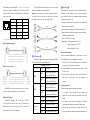
The pinout of RJ45 port display as below, connect by UTP or
STP. The connect distance is no more than 100m. 100Mbps is
used 120Ω of UTP 5; 10Mbps is used 120Ω of UTP 3, 4, 5.
1. Restore factory settings
2. Console port
3. Link/ACT LED
【Power supply input】
4. Systems running LED
The IES1024 series Ethernet switch have singe power and
5. Relay alarm LED
redundancy power two kinds of power input. The singe power
6. The power LED
series rear panel provides 5 bit wiring terminal for AC100~240V
RJ 45 port support automatic MDI/MDI-X operation. Can
connect the PC, Server, Converter and HUB .Pin 1,2,3,6