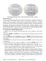
1
Pub. 988-0151-222
www.lowrance.com
LMF-400
Multi-function Gauge
Installation and Operation
Instructions
Busse-Yachtshop.de
[email protected]
Copyright © 2006 Lowrance Electronics, Inc.
All rights reserved.
No part of this manual may be copied, reproduced, republished,
transmitted or distributed for any purpose, without prior written
consent of Lowrance Electronics. Any unauthorized commercial
distribution of this manual is strictly prohibited.
Lowrance Electronics may find it necessary to change or end our
policies, regulations and special offers at any time. We reserve the right
to do so without notice. All features and specifications subject to change
without notice. On the cover: LMF-400.
For free owner's manuals and other information,
visit our web site:
www.lowrance.com
Lowrance Electronics Inc.
12000 E. Skelly Dr.
Tulsa, OK USA 74128-2486
Printed in USA.
Busse-Yachtshop.de
[email protected]
Table of Contents
Section 1: Introduction............................................................. 1
Section 2: Installation............................................................... 3
Preparation .................................................................................... 3
Recommended Tools and supplies............................................ 3
Installation Sequence................................................................ 3
Mounting the Gauge ..................................................................... 3
Connecting to a NMEA 2000 Network .................................... 5
Compatibility ............................................................................. 5
Network Backbone and Network Nodes .................................. 5
Adding a Network Node............................................................ 6
Additional NMEA information ................................................. 7
Understanding this manual ......................................................... 8
Up and Down ............................................................................. 8
Menu .......................................................................................... 8
Pages/Enter................................................................................ 8
Exit ............................................................................................. 8
Menu Commands....................................................................... 8
Instructions = Menu Sequences ............................................... 8
Section 3: Operation.................................................................. 9
Boat Setup ..................................................................................... 9
Basic Menu .................................................................................. 10
Pages ............................................................................................ 10
Viewing Pages (Page Screen Rotation) ...................................... 10
Page Options................................................................................ 11
Engine Trim............................................................................. 11
Diagnostics............................................................................... 11
Fuel Manager .......................................................................... 11
GPS Position ............................................................................ 11
Rudder...................................................................................... 11
Single Analog........................................................................... 12
Dual Analog ............................................................................. 12
Quad Analog ............................................................................ 12
Single Digital ........................................................................... 12
Dual Digital ............................................................................. 12
Quad Digital ............................................................................ 12
Synchronizer ............................................................................ 12
Trim Tabs................................................................................. 13
Pages Menu ................................................................................. 13
Add Page .................................................................................. 13
Remove Page............................................................................ 14
Page Scrolling .......................................................................... 14
i
Busse-Yachtshop.de
[email protected]
Pop-Ups Setup ............................................................................. 14
Screen........................................................................................... 16
Backlight.................................................................................. 16
Backlight Sync (BLight Sync)................................................. 17
Contrast ............................................................................... 17
Reverse Video .......................................................................... 18
Audio Setup ................................................................................. 18
Key Sounds .............................................................................. 18
Alarm Sound ............................................................................ 19
System Setup Menu .................................................................... 19
Engine Data ......................................................................... 19
Engine Warnings................................................................. 19
Bus Devices.......................................................................... 20
Sonar Alarms ........................................................................... 20
Engine/Tank Configuration ................................................ 21
Reset Values: ....................................................................... 22
NMEA Info............................................................................... 23
System Information................................................................. 23
Speed Range ........................................................................ 23
Pressure Ranges .................................................................. 23
Change Units ........................................................................... 24
Fuel Setup.................................................................................... 26
Refill Tank ............................................................................... 26
Partial Fill................................................................................ 27
Economy Speed Source ........................................................... 27
Fuel Remaining Source........................................................... 28
Reset Trip Fuel ........................................................................ 28
Reset Seasonal......................................................................... 29
Customizing Pages ...................................................................... 29
Single Analog........................................................................... 30
Dual Analog ............................................................................. 31
Quad Analog ............................................................................ 31
Single Digital ........................................................................... 32
Dual Digital ............................................................................. 32
Quad Digital ............................................................................ 34
Trim Tabs................................................................................. 35
Fuel Manager .......................................................................... 35
Section 4: EP Configuration & Calibration....................... 37
EP-35 Temperature Configuration ............................................ 37
EP-10 Fuel Flow Configuration ................................................. 39
EP-15 Fluid Level Configuration ............................................... 42
Fluid Level menu .................................................................... 43
Reset Values ............................................................................ 47
ii
Busse-Yachtshop.de
[email protected]
Suzuki Engine Interface Configuration..................................... 48
Calibrating EP Sensors............................................................... 51
Calibrating EP-10 Fuel Flow...................................................... 52
Fuel Flow Accuracy ................................................................. 52
Refill Tank ........................................................................... 52
Reset Calibration................................................................. 54
Partial Fill............................................................................ 54
Calibrating EP-15 Fluid Level ............................................... 54
2-Point Calibration.................................................................. 55
3-Point Calibration.................................................................. 55
5-Point Calibration.................................................................. 56
Reset Calibration................................................................. 57
Calibrating Fuel Flow in a Suzuki Engine Interface................ 58
Engine Interface Accuracy...................................................... 58
Refill Tank ........................................................................... 59
Reset Fuel Calibration ........................................................ 60
Partial Fill............................................................................ 60
Calibrating EP-30 Trim Tabs ..................................................... 61
iii
Busse-Yachtshop.de
[email protected]
Notes
iv
Busse-Yachtshop.de
[email protected]
Section 1: Introduction
Thank you for buying the Lowrance® LMF-400! Your unit is a highquality, multi-function, digital gauge designed to work with a
LowranceNET™ network. This is the NMEA 2000® networking system
developed by Lowrance Electronics.
Caution:
Installing LowranceNET NMEA 2000 devices is significantly
different from installing earlier Lowrance components without
NMEA 2000 features. You should read all of the installation
instructions before proceeding.
This gauge will only work with a NMEA 2000 network. It MUST be
connected to a NMEA 2000 network or it WILL NOT function. When
properly installed, the LMF-400 will display information from a variety
of Lowrance Electronic Probe (EP) sensors and other NMEA 2000
devices connected to the network.
A NMEA 2000 network using LowranceNET components.
All Lowrance NMEA 2000 capable devices are either NMEA 2000
certified or certification is pending. See our web site, www.lowrance.com,
for the latest product information.
To get started with your Lowrance gauge, read Section 2: Installation.
After you have read those instructions, install the gauge and any EP
sensors you may have purchased, then read the rest of this manual.
Each sensor comes with its own installation instruction sheet, but this
manual describes how the gauge operates with each sensor and how to
configure and calibrate the sensors.
Your gauge packaging also includes the NMEA 2000 Networks General
Information. It contains instructions for creating or expanding a NMEA
2000 network.
1
Busse-Yachtshop.de
[email protected]
LowranceNET teams up the powerful NMEA 2000 network standard
with a fast-growing, cutting-edge family of Lowrance Electronic Probe
Sensors. The product line includes the EP-10 Fuel Flow, EP-15 Fluid
Level, Suzuki Engine interface, EP-25 Speed, EP-35 Temp, EP-45
Pressure sensors and EP-50 Storage device.
And what's more exciting, there are others on the way. Be sure to log
on to our website, www.lowrance.com, from time to time for the latest
developments, including updated operation manuals, instruction sheets
and software you can download free of charge. When you are ready to
expand your network, see the accessory ordering information on the
back cover of this manual.
NOTICE!
The storage and operation temperature range for your unit is from
-4 degrees to +167 degrees Fahrenheit (-20 degrees to +75 degrees
Celsius). Extended storage or operation in temperatures higher or
lower than specified will damage the liquid crystal display in your unit.
This type of damage is not covered by the warranty. For more
information, contact the factory's Customer Service Department; phone
numbers are inside the manual's back cover.
2
Busse-Yachtshop.de
[email protected]
Section 2: Installation
Preparation
The design of the LMF-400 allows convenient mounting in the dash of
your boat, or it can be mounted on any flat panel at least four inches in
diameter.
To mount the LMF-400 in the dash, first make sure there is sufficient
clearance behind the panel in the desired location. At least 3-1/2 inches are
needed behind the surface of the dash to clear all connectors and wiring.
Recommended Tools and supplies
Recommended tools for this job include: hole saw, 3/38" (86 mm) hole
saw bit, drill, 1/8" (3 mm) drill bit (for starter hole). Required supplies
for this job include: "U" bracket, lock washers and wing nuts (included).
Installation Sequence
You can install this gauge in some other order if you prefer, but we
recommend the installation sequence listed below.
1. Determine the location for the gauge so you can plan how and where
to route the cables. This will help you make sure you have enough cable
length for the desired configuration.
2. Determine the location of the nearest device on the boat's NMEA
2000 network, along with the route of the gauge's network cable.
3. Determine the location for the alarm buzzer and its wire route.
4. If you want the gauge's backlight to turn on when the dashboard
lights are turned on, locate your boat's dash light switch and determine
how to route the gauge's dash light wires to it.
5. Install the gauge in a standard 3-3/8 inch (86 mm) hole in the dash.
If no 3-3/8 hole available in the dash, you will have to drill a 1/8" pilot
hole, then use a hole saw to cut a mounting hole. See instructions for
Mounting the Unit below.
6. Connect the buzzer wires and install the buzzer. If desired, connect
the dash light wires to the boat's dash light switch.
7. Connect the network cable to the NMEA 2000 network.
Mounting the Gauge
If no standard mounting hole is available in the dash, drill a 1/8" pilot
hole, then cut a 3-3/8 inch (86 mm) diameter mounting hole with a hole
saw. A "U" bracket is supplied to hold the unit to the dash. Place it over
the threaded studs on the back of the unit and secure it with the lock
washers and nylon wing nuts provided with the unit.
3
Busse-Yachtshop.de
[email protected]
Secure unit to the dash using "U" bracket as shown.
The bracket is designed to secure the unit to a dash with a thickness of
2 mm. If your dash is thicker than 2 mm, the "U" bracket will be too
long. Simply place washers or spacers between the unit and the bracket
until you can tighten the wing nuts and secure the unit in place. You
are now ready to wire the unit to the buzzer (piezo) and dash lights.
Yellow wire:
Piezo ground
LMF-400
Housing
Blue wire:
Piezo positive
White wire:
Dash light
positive
Black wire:
Dash light
ground
LMF-400
NMEA
2000
Network
Cable
LMF-400 with power cable wiring and NMEA 2000 Cable Connection.
Connecting the LMF-400 to the buzzer (piezo), will enable the buzzer to
sound when buttons are pressed and when alarms and level warnings
are triggered. Wiring the unit to the boat's dash lights, will turn on the
LMF-400 backlight when the dash lights are turned on.
4
Busse-Yachtshop.de
[email protected]
If you do not want to use the buzzer or dash light wires, clip the bare
ends off the wires, then cap them with wire nuts or electrical tape.
To wire unit to the buzzer (piezo):
1. Connect the LMF-400 yellow wire to the buzzer (piezo) ground wire.
2. Attach the LMF-400 blue wire to the buzzer (piezo) positive wire.
3. Select a buzzer location that is protected from the elements, but will
still allow you to hear it. Use the adhesive back on the buzzer to mount
the buzzer to a flat, clean surface.
To wire unit to dash lights:
1. Connect the LMF-400 black wire to the dash light ground wire.
2. Now attach the LMF-400 white wire to the dash light positive wire.
Connecting to a NMEA 2000 Network
A network bus is an installed and operational network cable (backbone)
running the length of your boat, already connected to a power supply
and properly terminated. It provides network connection nodes at
various locations around your boat.
Compatibility
You will easily be able to connect your unit to both red (DeviceNet) and
blue connector networks, regardless of whether your unit has a blue or
red connector network cable. Check the adapter cable segment in the
Setup and Installation of NMEA 2000 Networks, General Information"
that came packed with your unit. If you do not have that document, it
can be downloaded free from the Lowrance web site.
LowranceNET Node Kit for a NMEA 2000 network. Includes a 2 foot
extension cable, T connector, 120-ohm male terminator and 120-ohm
female terminator.
Network Backbone and Network Nodes
A network bus backbone consists of network cabling, terminators and T
connectors. Network nodes are made by fitting T-shaped connectors into
the backbone (using the sockets on the sides) and attaching any network
device to the bottom of the T.
5
Busse-Yachtshop.de
[email protected]
Adding a Network Node
You can add a node to any existing connection, anywhere along the
network backbone. This connection could be between a T connector and a
terminator, between two T connectors, between a T connector and a
backbone extension cable or between two extension cables. Wherever you
want to add the new node, separate the sockets of the existing connection
and install the T connector between them.
Lowrance or LEI device connects to new T connector.
Add T-shaped connector to add device
to bus.
Attach
terminator at
end of bus.
Existing network
node
Add a new device to a NMEA 2000 bus (above) by attaching a T
connector between two T connectors, between a T connector and the
end terminator, or between two backbone extension cables. The red
connector network (below) is built in the same way. Notice the Double
T connectors on the red connector network.
Add T-shaped or double T connector to add
device to bus (maintaining linear architecture)
Attach
terminator at
end of bus
Backbone cable
to rest of bus
Existing network
node
Devices connect to
Double T connector
If you want to add a node at the end of the backbone (network bus)
remove the terminator from the last connector, like the figure above.
Install the new T connector, then attach the terminator to the side of the
connector.
6
Busse-Yachtshop.de
[email protected]
NOTE:
If you add an EP-10 Fuel Flow, EP-15 Fluid Level, EP-45 Water
Pressure or EP-50 Storage Device sensor to the network, you must
go through Boat Setup so the engine-tank configuration will be
consistent among the sensors in the LowranceNet. Follow the Boat
Setup procedure included in Section 3: Operation.
Additional NMEA information
For more detailed information about setting up a NMEA 2000 network,
refer to the "Setup and Installation of NMEA 2000 Networks, General
Information" that came with your unit. If you do not have that
document, it can be downloaded free from the Lowrance web site.
7
Busse-Yachtshop.de
[email protected]
Understanding this manual
Most instructions in the manual are listed as numbered steps. Keypad
commands appear as boldface type, making it easy to skim through
instructions and pick out what command to use.
Up and Down
The Up and Down keys help you navigate through menus, select
(highlight) menu items, and are used to make adjustments to numbers
in dialog boxes. They are shown as UP and DOWN in this manual.
Menu
When instructed to press the menu key, menu will be shown as MENU.
The menu key is used to access the main menu.
Pages/Enter
The Pages/Enter key is used to execute commands and to scroll forward
through pages set for display on the main screen. The Pages/Enter key
will be shown as ENTER in this manual.
Exit
The Exit key is used to close menus and remove dialogs, windows and
messages from the screen. Shown as EXIT in this manual, it is also used
to scroll backward through pages set for display on the main screen.
Menu Commands
A menu command or a menu option will appear in small capital letters,
like — SYSTEM SETUP. When you see a word in command text, you are
supposed to take action, by selecting (highlighting) this command or
option from a menu.
Instructions = Menu Sequences
Most functions performed with this unit are described as a sequence of
keystrokes.
Instructions for accessing a menu will look like this:
1. To access the Bus Devices list, press MENU, use the UP and
DOWN keys to select SYSTEM SETUP and press ENTER.
2. Highlight BUS DEVICES and press ENTER. The Bus Devices list
will appear, showing all devices on your NMEA 2000 network.
8
Busse-Yachtshop.de
[email protected]
Section 3: Operation
The displays and settings in this digital gauge are controlled by a fivebutton keypad. The buttons are UP, DOWN, MENU, ENTER and EXIT. The
MENU key gives you access to the basic menu. The UP and DOWN keys
are used to scroll through and highlight menu items. The PAGES/ENTER
key (also referred to as the ENTER key) allows you to scroll forward
through pages, execute commands and select items from menus. The
EXIT key is used to close menus and scroll backward through pages.
LMF-400 keypad.
Boat Setup
When the LMF-400 is turned on the first time, the Boat Setup menu
will appear. You will not be able to proceed without completing Boat
Setup. If, however, you have one or more of the following devices —
Suzuki Engine Interface, EP-10 Fuel Flow, EP-15 Fluid Level, EP-45
Pressure Sensor or an EP-50 Storage Device — already configured in
the network with the same engine-tank configuration, you WILL NOT
have to go through boat setup when adding a new gauge to the
network. After adding the gauge to the network, the Boat Setup menu
will be cleared from the screen and the unit will begin normal
operation in 1-2 seconds.
NOTE:
If you add an EP-10 Fuel Flow, EP-15 Fluid Level, EP-45 Water
Pressure or EP-50 Storage Device sensor to the network, you must
go through Boat Setup so the engine-tank configuration will be
consistent among sensors on the network.
To execute Boat Setup:
1. With Boat Setup highlighted on the screen, press ENTER. A menu
will appear, allowing you to choose the number of engines and fuel
tanks on your vessel. The Boat Setup menu options are: 1 Eng/1 Tank,
1 Eng/2 Tank, 2 Eng/1 Tank, 2 Eng/2 Tanks, 3 Eng/1 Tank or 3 Eng/3
Tanks.
9
Busse-Yachtshop.de
[email protected]
2. Use the UP and DOWN keys to select the engine-tank configuration
that applies to your vessel and press ENTER. After setting the
engine/tank configuration, the Tank Size menu will appear with up to
three options (Port Tank, Center Tank and Starboard Tank), depending
on the engine tank configuration you chose. (If you selected one tank
during Boat Setup, you will be taken directly to the Setting Tank Size
Window in Step 4.)
3. Select the desired tank and press ENTER, which will open the Setting
Tank Size window.
4. Use the UP and DOWN keys to input the number of gallons the tank
will hold and press ENTER.
Press EXIT and repeat steps 3 and 4 for each of the remaining tanks.
5. After all tanks on your vessel have been set up, press EXIT repeatedly
to get back to the main display.
NOTE:
If you chose the wrong engine-tank configuration during Boat
Setup, you will have to reset your engine-tank configuration to get
back to Boat Setup. To reset engine-tank configuration, see enginetank configuration instructions on page 21.
Basic Menu
The LMF-400 has 13 page screens that can be customized with the data
of your choosing. Each page has its own basic menu. Basic menus vary
from page to page, but all contain these standard menu options: Pages,
Screen, Audio Setup and System Setup. Pages that can be customized
also include Customize on the basic menu.
Pages
Your unit can display up to 16 page screens. You could, for example,
add 12 different pages then add some pages more than once,
customizing them differently each time.
Viewing Pages (Page Screen Rotation)
The Page Screen Rotation consists of multiple pages that have been set
up for display. Once pages have been added to the page screen rotation,
they can be set to scroll across the screen automatically or manually.
Use the ENTER and EXIT keys to manually scroll pages across the
screen. Pressing the ENTER key moves the scroll in one direction.
Pushing the EXIT key moves the scroll in the other direction. You will
use the Page Scrolling feature to set up pages for automatic scrolling.
See page 14 for more information about Page Scrolling.
10
Busse-Yachtshop.de
[email protected]
Page Options
The LMF-400 has 12 different pages that may be added to the page
screen rotation. They are: Engine Trim, Diagnostics, Fuel Manager,
GPS Position, Single Analog, Dual Analog, Quad Analog, Single
Digital, Dual Digital, Quad Digital, Synchronizer, Trim Tabs and
Rudder.
Engine Trim (from left to right), Diagnostics, Fuel Manager and GPS
Module page.
Engine Trim
The Engine Trim page displays engine position data as an analog slider
bar and as a percentage. It cannot be customized.
Diagnostics
The Engine Diagnostic page displays engine performance data. It
cannot be customized.
Fuel Manager
The Fuel Manager page has a digital readout capable of displaying
nine data types, including fuel flow, fuel used and fuel remaining.
GPS Position
The GPS position page displays the boat’s position in LatitudeLongitude, using Degrees-Minutes or Degrees-Minutes-Seconds as the
units of measure.
Single Analog (from left to right), Dual Analog, Quad Analog and
Single Digital page.
Rudder
The Rudder Page displays the rudder position as an analog gauge and
in degrees. It cannot be customized.
11
Busse-Yachtshop.de
[email protected]
Single Analog
The Single Analog page consists of a single analog gauge that can be
customized to display a wide assortment of data, ranging from
Alternator Voltage and Water Speed to Battery Voltage and
Tachometer.
Dual Analog
The Dual Analog page features two analog gauges stacked one on top of
the other. Both gauges can be customized to display a wide assortment
of data including, Atmospheric Pressure, Engine Boost Pressure, Fuel
Pressure and Fluid Level.
Quad Analog
The Quad Analog page is divided equally into four parts, each
containing a small analog gauge. All four gauges can be customized to
display a wide range of data, from Pitot Speed and Engine
Temperature to Oil Pressure and Transmission Oil Pressure.
Single Digital
The Single Digital page consists of a digital data box that can be
customized to display a wide assortment of data that includes Battery
Voltage, Water Speed and Tachometer.
Dual Digital (from left to right), Quad Digital, Synchronizer and Trim
Tabs page.
Dual Digital
The Dual Digital page features two digital data boxes that can be
customized to display a wide assortment of data including, Engine Oil
Pressure, Engine Load and Total Engine Hours.
Quad Digital
The Quad Digital page has four customizable digital data boxes stacked
one on top of the other capable of displaying a wide range of data, from
Seasonal Fuel and Fuel Used to Depth and Temperature.
Synchronizer
The Synchronizer page displays RPM for up to three engines. It allows
users to synchronize engines for smoother performance. The
Synchronizer page cannot be customized and will NOT be available for
single-engine configurations.
12
Busse-Yachtshop.de
[email protected]
Trim Tabs
The Trim Tab page monitors the position of the Trim Tabs using
degrees or percentages as units of measure.
Scrolling list of page options (left) with basic menu options (right).
Pages Menu
The Pages menu can be accessed from any of the page displays. It has
four options: Add Page, Remove Page, Page Scrolling and Pop-Ups
Setup.
Add Page
The Add Page command allows you to add pages to the page screen
rotation. Pages that are not added to the page screen rotation will not
be displayed.
NOTE:
Only pages added to the page screen rotation will be displayed.
To add a page to the display:
1. Press MENU, use the UP and DOWN keys to select PAGES and press
ENTER. A menu will pop up with four options: Add Page, Remove Page,
Page Scrolling and Pop-Ups Setup.
2. Select ADD PAGE and press ENTER.
3. Highlight the page you want to display and press ENTER. The
following message will appear: Press Enter to add the selected page.
4. Press ENTER, which will take you back to the main display, where
the page you chose will be shown on the screen.
NOTE:
The LMF-400 can have up to 16 pages in the page screen rotation
at one time. If you try to add a 17th page, the following message
will appear: Number of Pages has Reached Max. In that case, you
will have to remove a page before another page can be added to the
page screen rotation.
13
Busse-Yachtshop.de
[email protected]
Remove Page
The Removing Pages command allows you to remove pages from the
page screen rotation. Before selecting Remove Pages, make sure the
page you want to remove is displayed on the screen.
To remove a page from the display:
1. First, scroll the page you want to remove on to the screen. Press
MENU, use the UP and DOWN keys to select PAGES and press ENTER.
2. Highlight REMOVE PAGE and press ENTER. The following message will
appear: Press Enter to Remove current Page.
3. Press ENTER, which will take you back to the main display.
Page Scrolling
Once all the pages you want to monitor have been added to the page
screen rotation, you will be able to view them in two ways. You can
scroll through pages manually by using the ENTER and EXIT keys or
utilize the Page Scrolling function to have pages automatically scroll
across the screen at an interval of your choosing.
To activate Page Scrolling:
1. Press MENU, use the UP and DOWN keys to select PAGES and press
ENTER.
2. Select PAGE SCROLLING and press ENTER. The Page Scrolling menu will
appear with two settings: Off and Set Time.
3. Highlight SET TIME and press ENTER. (You would select OFF to turn off
Page Scrolling.)
4. Use the UP and DOWN keys to select an interval between one and 60
seconds and press ENTER. You will be taken back to the main display.
Pop-Ups Setup
This feature helps you keep tabs on the RPM, Engine Trim, Trim Tab
and Rudder pages by launching a pop up window if selected thresholds
for any of the data types are exceeded. If, for example, you set the RPM
threshold to 500 RPM and choose a 10-second Stay on Time, the RPM
page will pop up if there is a change in RPM that exceeds 500 RPM —
like decreasing RPM from 2000 RPM to 1300 RPM. The pop up will
expire 10 seconds after the data that exceeded the threshold stops
changing. The gauge will revert to the page it was showing before the
threshold was exceeded.
To set RPM Pop up:
1. Press MENU, use the UP and DOWN keys to select PAGES and press
ENTER.
2. Highlight POP-UPS SETUP and press ENTER.
14
Busse-Yachtshop.de
[email protected]
3. The Pop-Ups Setup menu will appear with five options: RPM, Engine
Trim, Trim Tabs, Rudder and Stay-on Time. Select RPM and press
ENTER. The RPM menu will appear with two options: Off and Set
Threshold.
4. Highlight SET THRESHOLD and press ENTER. (You would select OFF to
turn off the pop-up.)
NOTE:
In a multiple engine configuration, the next step would be to select
the engine.
5. Use the UP and DOWN keys to select a threshold between 50 and
3,000 RPM and press ENTER. You will be taken back to the main
display.
To set Engine Trim Pop-up:
1. Press MENU, use the UP and DOWN keys to select PAGES and press
ENTER.
2. Highlight POP-UPS SETUP and press ENTER.
3. Select ENGINE TRIM and press ENTER. The Engine Trim menu will
appear with two options: Off and Set Threshold.
4. Highlight SET THRESHOLD and press ENTER. (You would select OFF to
turn off the pop-up.)
5. Use the UP and DOWN keys to select a threshold between 3% and
50% and press ENTER. You will be taken back to the main display.
To set Trim Tabs Pop up:
1. Press MENU, use the UP and DOWN keys to select PAGES and press
ENTER.
2. Highlight POP-UPS SETUP and press ENTER.
3. Select TRIM TABS and press ENTER. The Trim Tabs menu will appear
with two options: Off and Set Threshold. (You would select OFF to turn
off the pop-up.)
4. Highlight SET THRESHOLD and press ENTER.
5. Use the UP and DOWN keys to select a threshold between 3% and
50% and press ENTER. You will be taken back to the main display.
To set Rudder pop-up:
1. Press MENU, use the UP and DOWN keys to select PAGES and press
ENTER.
2. Highlight POP-UPS SETUP and press ENTER.
3. Select RUDDER and press ENTER. The Rudder menu will appear with
two options: Off and Set Threshold.
4. Highlight SET THRESHOLD and press ENTER. (You would select OFF to
turn off the pop-up.)
15
Busse-Yachtshop.de
[email protected]
5. Use the UP and DOWN keys to select a threshold between 3 and 40
degrees. Press ENTER. You will be taken back to the main display.
Stay-On Time:
The Stay-On Time command allows you to choose how long a pop-up
will remain on the screen after the data stops moving. The Stay-On
Time setting will affect all four Pop-up Pages.
1. Press MENU, use the UP and DOWN keys to select PAGES and press
ENTER.
2. Highlight POP-UPS SETUP and press ENTER.
3. Select STAY-ON TIME and press ENTER.
4. Use the UP and DOWN keys to input the amount of time a pop up will
remain on the screen. The stay-on time for a pop up may be set
between 2 and 15. Press ENTER. You will be taken to the main display.
Basic menu with Screen highlighted (left). Screen option menu
(center) with Set Backlight window (right).
Screen
Accessing the Screen menu allows you to make adjustments to the
appearance of the screen. There are three options: Backlight, Contrast
and Reverse Video.
Backlight
The Backlight feature allows you to brighten or dim the light in the
LMF-400.
To adjust Backlight:
1. Press MENU, use the UP and DOWN keys to select SCREEN and press
ENTER.
2. Highlight BACKLIGHT and press ENTER. The Backlight menu will
appear with two options: BLight Sync (Backlight Sync) and Adjust.
3. Select ADJUST and press ENTER.
4. A vertical scrollbar will appear. Use the UP and DOWN keys to set the
backlight to a desired level. Press EXIT to return to the Backlight menu.
16
Busse-Yachtshop.de
[email protected]
Backlight Sync (BLight Sync)
By turning on the Backlight Sync function, all the backlight levels for
components on the LowranceNet may be controlled by any of the
gauges or head units in the network. If you adjust the backlight on one
of the gauges or display units, the backlight levels from the other
gauges and display units will be changed, too. Backlight Sync will be on
by default.
To set Backlight Sync:
1. Press MENU, use the UP and DOWN keys to select SCREEN and press
ENTER.
2. Highlight BACKLIGHT and press ENTER. The Backlight menu will
appear with two options: BLight Sync (Backlight Sync) and Adjust.
3. Highlight BLIGHT SYNC and press ENTER, which will open the BLight
Sync menu with two options: On and Off. Turning on Backlight Sync
will cause the backlight level for all gauges on the LowranceNet to be
synchronized with the backlight level on your LMF-400.
4. Select the desired option (ON or OFF) and press ENTER to be directed
to the main display.
Contrast
The Contrast feature allows you to darken or lighten the display
screen. If you have more than one gauge, each gauge's contrast is
adjusted individually. Contrast is not synchronized over the network.
To adjust Contrast:
1. Press MENU, use the UP and DOWN keys to select SCREEN and press
ENTER. Select CONTRAST from the Screen menu and press ENTER, which
will launch the Contrast Adjustment vertical scrollbar.
2. Use the UP and DOWN keys to move the bar to a desired level.
3. Press EXIT to return to the Screen menu or press ENTER to return to
the main display.
Contrast is highlighted on the Screen menu (left). The Contrast Adjust
window (center). Reverse Video highlighted on Screen menu (right).
17
Busse-Yachtshop.de
[email protected]
Reverse Video
The Reverse Video function swaps the position of dark and light colors
on the screen. The dark text, which is on top of a light background, will
be switched to light text on top of a dark background. This feature,
typically, is used to darken the display for nighttime use.
NOTE:
The Reverse Video command is transmitted over the network, so all
gauges will be synchronized to the same Reverse Video setting.
To turn on Reverse Video:
1. Press MENU, use the UP and DOWN keys to select SCREEN, and press
ENTER.
2. Highlight REVERSE VIDEO and press ENTER. You will notice the dark
and light colors have been swapped for one another.
3. To switch Reverse Video to its previous setting, return to the Screen
menu, select REVERSE VIDEO and press ENTER.
4. Press EXIT|EXIT to return to the main display.
Audio Setup highlighted on the basic menu (left). Audio
Setup menu (center) with Key Sounds menu (right).
Audio Setup
Audio Setup gives you access to the unit's audio functions. There are
two options on the Audio Setup menu: Key Sounds and Alarm Sounds.
Key Sounds
When Key Sounds are turned on, a tone will sound every time you push
the UP, DOWN, MENU, ENTER and EXIT keys. When you turn off Key
Sounds, no tone will sound when you depress the keys.
To turn Key Sounds on/off:
1. Press MENU, use the UP and DOWN keys to select AUDIO SETUP, and
press ENTER. A menu will appear with two options: Key Sounds and
Alarm Sound.
2. Select KEY SOUNDS and press ENTER. The Key Sounds menu will
appear with two options: On and Off.
18
Busse-Yachtshop.de
[email protected]
3. Highlight ON to turn Key Sounds on or OFF to turn Key Sounds off.
Press ENTER. You will be taken back to the main display.
Alarm Sound
When an alarm is set and Alarm Sound is turned on, you will hear a
tone and see a pop-up window when an alarm is triggered. With an
alarm set and Alarm Sound turned off, you will see a pop-up window,
but no tone will sound.
To turn Alarm Sound on/off:
1. Press MENU, use the UP and DOWN keys to select AUDIO SETUP and
press ENTER. A menu will appear with two options: Key Sounds and
Alarm Sound.
2. Highlight ALARM SOUNDS and press ENTER. The Alarm Sound will
appear with two options: On and Off.
3. Select ON to turn on Alarm Sound or select OFF to turn off Alarm
Sound. Press ENTER. You will be taken back to the main display.
System Setup Menu
The System Setup menu contains the following features: Engine Data,
Engine Warnings, Change Units, Fuel Setup, Bus Devices, Sonar
Alarms, Eng/Tank Configuration, Reset Values, NMEA Information
and System Information. Speed Range and Pressure Range are
included on the System Setup menu on the Synchronizer, Engine Trim,
Single Analog and Trim Tab pages.
Engine Data
The Engine Data feature allows you to select an engine (Port, Center or
Starboard) to be the primary engine shown on pages that display
engine data.
To modify Engine Data:
1. Press MENU, select SYSTEM SETUP and press ENTER.
2. Highlight ENGINE DATA and press ENTER to open the Select Engine
menu with three options (Port, Center and Starboard), depending on
the engine-tank configuration you chose.
3. Select the engine (Port, Center or Starboard) you want to have
displayed and press ENTER. A confirmation message will appear. If, for
example, you selected the Port engine the following message will
appear: Press Enter to change to Port Engine.
4. Press ENTER. Pages that display engine data will now show data
from the selected engine. You will be taken back to the main display.
Engine Warnings
The Engine Warnings feature allows you to set an alarm for one or
more engines. There are up to five options in the Engine Alarms menu,
19
Busse-Yachtshop.de
[email protected]
depending on the number of engines chose during Boat Setup. The
options are All Engines, Port, Center, Starboard and Off. The default
setting is All Engines. (If you have a single-engine configuration, the
only options on the Engine Warning menu will be on and off.)
1. Press MENU, use the UP and DOWN keys to highlight SYSTEM SETUP,
and press ENTER.
2. Highlight ENGINE WARNINGS and press ENTER to access the Engine
Warnings menu.
3. Choose the desired option and press ENTER. You will be taken back
to the main display. If you choose All Engines, the alarm will be shown
for each alarm that has been set. If Port, Center or Starboard engines
are selected, the gauge will only show warnings coming from the
chosen engine. (To turn off all engine warnings, highlight OFF and press
ENTER. If you turn off engine alarms, no alarms will be shown for any
of the engines.)
Bus Devices
The Bus Devices feature allows you to manage devices on the NMEA
2000 network. Accessing devices from the Bus Devices list gives you
access to an EP sensor's internal menu. We will cover that in more
detail in Section 4: EP Configuration and Calibration.
1. Press MENU, use the UP and DOWN keys to select SYSTEM SETUP and
press ENTER.
2. Highlight BUS DEVICES and press ENTER. The Bus Devices, a list of
network devices, will appear.
3. Press EXIT repeatedly to get back to the main display.
Sonar Alarms
Sonar alarms allow you to set alarms that will alert you as water depth
changes around your vessel. If the depth rises above (Deep Alarm) or
falls below (Shallow Alarm) thresholds of your choosing, an alarm will
sound.
To set the Shallow Alarm:
The shallow alarm will sound when your vessel enters water more
shallow than the selected shallow alarm threshold.
1. Press MENU, use the UP and DOWN keys to select SYSTEM SETUP and
press ENTER.
2. Highlight Sonar Alarms and press ENTER to open the Sonar Alarms
menu with two options: Shallow and Deep.
3. Select SHALLOW and press ENTER. The Shallow menu will appear with
two options: Off and Set Depth.
20
Busse-Yachtshop.de
[email protected]
4. Select SET DEPTH and press ENTER to open the Set Depth menu.
(Choose OFF to turn off the Shallow Alarm).
5. Use the UP and DOWN keys to set the alarm to the desired depth and
press ENTER. Press EXIT to return to the Sonar Alarms menu.
To set the Deep Alarm:
The deep alarm will sound when your vessel enters water deeper than
the selected deep alarm threshold.
1. Press MENU, use the UP and DOWN keys to select SYSTEM SETUP and
press ENTER.
2. Highlight Sonar Alarms and press ENTER to open the Sonar Alarms
menu with two options: Shallow and Deep.
3. Select DEEP and press ENTER. The Shallow menu will appear with
two options: Off and Set Depth.
4. Select SET DEPTH and press ENTER. (Choose OFF to turn off the Deep
Alarm).
5. Use the UP and DOWN keys to set the alarm to the desired depth,
then press EXIT repeatedly to get back to the main display.
Sonar Alarms highlighted on System Setup menu (left). Sonar Alarms
menu (center); Reset Values selected on System Setup menu (right).
Engine/Tank Configuration
The Engine/Tank configuration menu displays the number of engines
and fuel tanks on the vessel as well as fuel tank capacity. You selected
your engine-tank configuration during Boat Setup. If the selected
configuration is incorrect, you can return to Boat Setup by resetting the
configuration from the Engine/Tank Configuration menu.
To reset Eng/Tank configuration:
1. Press MENU, use the UP and DOWN keys to highlight SYSTEM SETUP and
press ENTER.
2. Select ENG/TANK CFG and press ENTER. The Engine Tank information
screen appears with the following message at the bottom of the page:
Press Enter to reset Cfg (configuration).
21
Busse-Yachtshop.de
[email protected]
3. Press ENTER and the following message will appear: Press Enter to
reset Eng/Tank Cfg.
4. Press ENTER, which will open the Boat Setup menu. Press ENTER,
then use the UP and DOWN keys to select an engine-tank configuration
that matches the number of engines and tanks on your vessel.
The Boat Setup menu options are: 1 Eng/1 Tank, 1 Eng/2 Tank, 2 Eng/1
Tank, 2 Eng/2 Tanks, 3 Eng/1 Tank or 3 Eng/3 Tanks.
5. Select the desired option and press ENTER, which will open the Tank
Size menu. The Tank Size men will have up to three options (Port
Tank, Cen Tank, Stbd Tank), depending on the engine tank
configuration you selected during Boat Setup. (If you selected one tank
during Boat Setup, you will not see any of these options. You will be
taken directly to the Setting Tank Size Window.)
6. Select a tank and press ENTER to open the Setting Tank Size
window.
7. Use the UP and DOWN keys to enter how many gallons the tank will
hold and press ENTER. Repeat steps 6 and 7 for each remaining tank.
NOTE:
If you have one tank, press ENTER after you have input the capacity
of the tank. Press EXIT repeatedly to get back to the main display.
8. After all tanks have been setup, press EXIT repeatedly to return to
the main display.
Reset Values:
The Reset command allows you to reset all values back to factory
default settings.
To reset values:
1. Press MENU, use the UP and DOWN keys to select SYSTEM SETUP and
press ENTER.
2. Select RESET VALUES and press ENTER. The following message will
appear: Press Enter to Reset All Values.
3. Press ENTER to reset values. You will be taken back to the main
display.
WARNING:
Resetting values is a hard reset. All LMF-400 settings
will be set back to factory defaults. Resetting values,
however, does not affect engine/tank configuration or
the calibration and configuration settings of devices on
the bus.
22
Busse-Yachtshop.de
[email protected]
NMEA Info
The NMEA information screen displays information about your NMEA
network, including address, instance, serial number and database
version.
To access the NMEA Information screen:
1. Press MENU, use the UP and DOWN keys to select SYSTEM SETUP and
press ENTER.
2. Highlight NMEA INFO and press ENTER. Press EXIT repeatedly to get
back to the main display.
System Information
Access the system information screen to see what version of software
you have in your LMF-400.
To access the System Information screen:
1. Press MENU, use the UP and DOWN keys to select SYSTEM SETUP and
press ENTER.
2. Highlight SYSTEM INFO and press ENTER. Press EXIT repeatedly to get
back to the main display.
Speed Range
The Speed Range function is included in the System Setup menus of
the following pages: Synchronizer, Single Analog, Dual Analog and
Quad Analog. The Speed Range feature can make on-screen gauges
easier to read by allowing you to choose a range that will better fit your
vessel’s speed capabilities. If, for example, your vessel's speed range is
0-40, the unnecessary figures (41-120) will only crowd the gauge
display, making it harder to read. Using the Speed Range feature
allows you to eliminate unnecessary figures from the display, giving it
better resolution. The default speed range is 0-40 mph.
To set Speed Range:
1. With the single analog, dual analog, quad analog or synchronizer
page on the screen, press MENU, use the UP and DOWN keys to select
SYSTEM SETUP, and press ENTER.
2. Highlight SPEED RANGE and press ENTER, which will open the Speed
range menu.
3. The Speed Range menu will appear with three options: 0-40, 0-80
and 0-120.
4. Select the desired range and press ENTER, which will take you back
to the main display.
Pressure Ranges
The Pressure Range screen is included in the System Setup menus of
the following pages: Synchronizer, Single Analog, Dual Analog and
23
Busse-Yachtshop.de
[email protected]
Quad Analog. Pressure Range can make on-screen gauges easier to
read by allowing you to select a range that will better fit your vessel’s
pressure range. If, for example, your vessel's water pressure range is 030 PSI, the unnecessary figures (31-100 PSI) will only crowd the gauge
display, making it harder to read. Using the Pressure Range feature
allows you to eliminate unnecessary figures from the display, giving it
better resolution.
To set Pressure Range:
1. With the single analog, dual analog, quad analog, synchronization
page on the screen, press MENU, use the UP and DOWN keys to select
SYSTEM SETUP and press ENTER.
2. Highlight PRESS RANGES (Pressure Ranges) and press ENTER, which
will open the Pressure range menu with the following options: Eng Wtr
Press (Engine Water Pressure), Eng Oil Press (Engine Oil Pressure),
Fuel Pressure, Eng Bst Press (Engine Boost Pressure) and Trns Oil
Press (Transmission Oil Pressure).
3. Select the desired pressure category and press ENTER. A menu will
appear with these options: 0-15 PSI, 0-30 PSI, 0-60 PSI, 0-80 PSI, 0100 PSI.
4. Highlight the desired pressure range and press ENTER. You will be
taken back to the main display.
Change Units
The CHANGE UNITS feature allows you to change the units of measure for
the following options: Speed/Distance, Temperature, Pressure, Depth,
GPS Coordinates and Volume.
System Setup menu (left) with Change Units highlighted. The Change
Units menu (right) with Speed/Distance selected.
To change Speed and Distance units:
Choosing Speed and Distance from the Change Units menu will allow
you to set the unit of measure for speed and distance to Statute,
Nautical or SI (Metric).
24
Busse-Yachtshop.de
[email protected]
1. Press MENU, use the UP and DOWN keys to select SYSTEM SETUP and
press ENTER.
2. Highlight CHANGE UNITS and press ENTER. Select SPEED/DIST and press
ENTER to open the Speed and Distance menu.
3. Select the desired option — STATUTE, NAUTICAL or SI (METRIC) — and
press ENTER. The unit of measure has been changed to the option you
selected. You will be directed to the main display.
To change Temperature units:
Accessing Temperature from the Change Units menu will allow you to
set the unit of measure for temperature to Fahrenheit or Celsius.
1. Press MENU, use the UP and DOWN keys to select SYSTEM SETUP and
press ENTER. Highlight CHANGE UNITS and press ENTER.
2. Select TEMPERATURE and press ENTER to open the Temperature menu.
3. Highlight the desired option — FAHRENHEIT or CELSIUS — and press
ENTER. The unit of measure has been changed to the option you
selected. You will be directed to the main display.
To change Pressure units:
Selecting Pressure from the Change Units menu will allow you to set
the unit of measure for pressure to Imperial/US or SI/Metric.
1. Press MENU, use the UP and DOWN keys to select SYSTEM SETUP and
press ENTER.
2. Highlight CHANGE UNITS and press ENTER. Select PRESSURE and press
ENTER to open the Pressure menu.
3. Choose the desired option — IMPERIAL/US or SI/METRIC — and press
ENTER. The unit of measure has been changed to the option you
selected. You will be directed to the main display.
To change Depth units:
Choosing Depth from the Change Units menu will allow you to set the
unit of measure for depth to Feet, Fathoms or Meters.
1. Press MENU, use the UP and DOWN keys to select SYSTEM SETUP and
press ENTER.
2. Highlight CHANGE UNITS and press ENTER. Select DEPTH and press
ENTER to open the Depth menu.
3. Choose the desired option — FEET, FATHOMS or METERS — and press
ENTER. The unit of measure has been changed to the option you
selected. You will be directed to the main display.
To change GPS units:
Selecting GPS Coord from the Change Units menu will allow you to set
the unit of measure for GPS coordinates to Deg/Min or Deg/Min/Sec.
1. Press MENU, use the UP and DOWN keys to select SYSTEM SETUP and
press ENTER.
25
Busse-Yachtshop.de
[email protected]
2. Highlight Change Units and press ENTER. Select GPS COORD and
press ENTER to open the GPS Coordinates menu.
3. Select the desired option — DEG/MIN or DEG/MIN/SEC — and press
ENTER. The unit of measure has been changed to the option you
selected. You will be directed to the main display.
To change Volume units:
Choosing Volume from the Change Units menu will allow you to set the
unit of measure for volume to US Gallons or Liters.
1. Press MENU, use the UP and DOWN keys to select SYSTEM SETUP and
press ENTER.
2. Highlight CHANGE UNITS and press ENTER. Select VOLUME and press
ENTER to open the Volume menu.
3. Select the desired option — US GALLONS or LITERS — and press ENTER.
The unit of measure has been changed to the option you selected. You
will be directed to the main display.
Fuel Setup
The following options may be accessed through the Fuel Setup menu:
Refill Tank, Partial Fill, Economy Speed Source, Fuel Remaining
Source, Reset Trip Fuel and Reset Seasonal Fuel.
Refill Tank
The Refill Tank command ensures the LMF-400 fuel reading is
consistent with the actual amount of fuel in your tank(s). The Refill
Tank command must be used with the EP-10 Fuel Flow, EP-50 Storage
Device and the Suzuki NMEA 2000 Engine Interface. The Refill Tank
command is NOT used when the EP-15 Fluid Level is used to read the
fuel level.
To refill tank:
1. Press MENU, use the UP and DOWN keys to select SYSTEM SETUP and
press ENTER.
2. Highlight FUEL SETUP and press ENTER.
3. Select REFILL TANK and press ENTER. The select Tank menu will
appear with up to three options (Port, Center and Starboard),
depending on the engine-tank configuration you chose during Boat
Setup. Select the tank you refilled and press ENTER. (If you have one
tank, you will be taken directly to the recalibration window mentioned
in step 4.)
NOTE:
If an EP-10 Fuel Flow or a Suzuki NMEA 2000 Engine Interface is
being used a menu will appear giving you the option to calibrate
fuel calculations. We will discuss calibration in Section 4:
Configuration and Calibration.
26
Busse-Yachtshop.de
[email protected]
4. A recalibration window will appear with two options: Yes and No.
Select NO and press ENTER. The following message will appear: Press
Enter after refilling the fuel tank.
NOTE:
You will only recalibrate when greater accuracy is necessary or
when default settings appear to be wrong. We will discuss
calibration in detail in Section 4: EP Configuration and Calibration.
5. Press ENTER. You will be directed back to the main display.
Partial Fill
The Partial Fill command is used when fuel is added to the tank, but
the tank is not filled completely. Partial Fill must be used with the EP10 Fuel Flow, EP-50 Storage Device and the Suzuki NMEA 2000
Engine Interface.
NOTE:
When using the Partial Fill command, you will only be able to input
an fuel amount less or equal to the fuel used figure. The unit will
not allow you to input a fuel amount greater than the fuel used
figure.
To use Partial Fill:
1. Press MENU, use the UP and DOWN keys to select SYSTEM SETUP and
press ENTER. Highlight FUEL SETUP and press ENTER.
2. Select PARTIAL FILL and press ENTER. The Select Tank menu will
appear with up to three options (Port, Center and Starboard),
depending on the engine-tank configuration you selected during Boat
Setup. (If you have one tank, you will be taken directly to the Adding
Fuel window.)
3. Select the desired tank and press ENTER. The Adding Fuel window
will appear.
NOTE:
When using the Partial Fill command, you will only be able to input
into the gauge, an amount of fuel less or equal to the fuel used
figure. The unit will not allow you to enter a fuel amount greater
than the fuel used figure.
4. Use the UP and DOWN keys to input the amount of fuel added to the
tank and press ENTER. You will be taken back to the main display.
Economy Speed Source
The Economy Speed menu allows you to choose what speed source the
LMF-400 will use to calculate Fuel Economy. A NMEA 2000 GPS
module, like the LGC-2000, measures ground speed The EP-25
Paddlewheel and NMEA 2000 Pitot tube measure water speed.
27
Busse-Yachtshop.de
[email protected]
NOTE:
Ground Speed is the default speed source for Fuel Economy.
To change Economy Speed source:
1. Press MENU, use the UP and DOWN keys to select SYSTEM SETUP and
press ENTER. Select FUEL SETUP and press ENTER.
2. Highlight ECO SPEED SRC and press ENTER to open the Economy Speed
menu. The menu has three options: Water Speed (Paddlewheel), Pitot
Speed and Ground Speed (GPS).
3. Select the desired speed source and press ENTER. You will be taken
back to the main display.
Fuel Remaining Source
The Fuel Remaining source function allows you to select the device
used to measure the amount the fuel remaining in the tank.
NOTE:
If you plan to use a fluid level sensor for a fuel tank, you must
switch the fuel remaining source to Fuel Level. If you want to use
the EP-10 Fuel Flow, EP-50 Storage Device or the NMEA 2000
Suzuki Engine Interface to measure fuel remaining, select
Engine/FFlow from the Fuel Remaining Source menu.
To change Fuel Remaining Source:
1. Press MENU, use the UP and DOWN keys to select SYSTEM SETUP and
press ENTER.
2. Highlight FUEL SETUP and press ENTER.
3. Select FUEL REM SRC (Fuel Remaining Source) and press ENTER.
4. Highlight the device you want to use to measure remaining fuel —
ENG/FFLOW (Engine Fuel Flow) or FLUID LEV SNSR (Fluid Level Sensor) —
and press ENTER. You will be taken back to the main display.
Reset Trip Fuel
A few sensors, like the Suzuki Engine Interface, EP-10 Fuel Flow and
EP-50 Storage Device keep a running total of fuel used for a trip. By
using the Reset Trip command, you can reset to zero the running total
of fuel used on a trip.
To reset trip fuel:
1. Press MENU, use the UP and DOWN keys to select SYSTEM SETUP and
press ENTER. Select FUEL SETUP and press ENTER.
2. Highlight RST TRIP FUEL and press ENTER. The Select Engine menu
will appear with up to four options (Port, Center, Starboard and All
Engines), depending on the engine-tank configuration you selected
during Boat Setup. (If you have one tank, the Press Enter to reset Trip
Fuel message will appear.)
28
Busse-Yachtshop.de
[email protected]
3. Select the desired option and press ENTER. The following message
will appear: Press Enter to reset Trip Fuel.
4. Press ENTER, which will reset the trip fuel and take you back to the
main display.
Reset Seasonal
A few sensors, like the Suzuki Engine Interface, EP-10 Fuel Flow and
EP-50 Storage Device keep a running total of fuel used for a season. By
using the Reset Seasonal command, you can reset to zero the running
total of fuel used for a season.
To reset seasonal fuel:
1. Press MENU, use the UP and DOWN keys to select SYSTEM SETUP and
press ENTER.
2. Highlight FUEL SETUP and p ress ENTER.
3. Select RST SEASONAL (Reset Seasonal) and press ENTER. The Select
Engine menu will appear with up to four options (Port, Center,
Starboard and All Engines), depending on the engine-tank
configuration you chose during Boat Setup. (If you have one engine, the
reset seasonal fuel message will appear.)
4. Select the desired option and press ENTER. The following message
will appear: Press Enter to reset Seasonal Fuel.
5. Press ENTER to reset seasonal fuel. You will be taken back to the
main display.
Customizing Pages
The customizing pages feature allows you to choose what data will be
displayed on selected pages. Pages that can be customized include:
Single Analog, Dual Analog, Quad Analog, Single Digital, Dual Digital,
Quad Digital, Fuel Manager and Trim Tab pages. The Engine Trim,
Engine Diagnostic, GPS Position and Synchronizer pages cannot be
customized.
NOTE:
Before a page can be customized it must be added to the page
screen rotation. (See the Adding Pages segment on page 13.) Once
it is in the rotation, scroll it onto the main display to access its
customize menu.
29
Busse-Yachtshop.de
[email protected]
Basic menu with Customize highlighted.
Single Analog
The Single Analog page may be customized to display these data types:
Alt Voltage, Battery Voltage, Engine Temp, Engine Water Pressure,
Engine Oil Pressure, Fuel Pressure, Engine Boost Pressure,
Transmission Oil Pressure, Atmospheric Pressure, Temperature, Fluid
Level, Water Speed (Paddlewheel), Ground Speed (GPS), and
Tachometer.
To customize Single Analog page:
1. Make sure the Single Analog page has been added to the page screen
rotation.
2. Use the ENTER and EXIT keys to scroll the Single Analog page onto
the main display.
3. Press MENU, use the UP and DOWN keys to select CUSTOMIZE and press
ENTER. The data menu will appear.
4. Select the data type you want to display and press ENTER. You will
be taken back to the main display where the Single Analog page will be
shown with the data you selected.
Single Analog page (left) with Dual Analog page (right).
30
Busse-Yachtshop.de
[email protected]
Dual Analog
The Dual Analog page consists of two analog gauges and may be
customized to show these data types: Alt Voltage, Battery Voltage,
Engine Temp, Engine Water Pressure, Engine Oil Pressure, Fuel
Pressure, Engine Boost Pressure, Transmission Oil Pressure,
Atmospheric Pressure, Temperature, Fluid Level, Water Speed
(Paddlewheel), Ground Speed (GPS), and Tachometer.
To customize Dual Analog page:
1. Make sure the Dual Analog page has been added to the page screen
rotation.
2. Use the ENTER and EXIT keys to scroll the Dual Analog page onto the
main display.
3. Press MENU, use the UP and DOWN keys to select CUSTOMIZE and press
ENTER. A menu will appear with two options: Top Gauge and Bottom
Gauge.
4. Select the desired gauge and press ENTER. The data menu will
appear.
5. Highlight the data category you want to display and press ENTER.
Repeat steps 1-5 for the other half of the page (Top Gauge or Bottom
Gauge).
6. Press EXIT|EXIT to return to the main display where the Dual Analog
page will be shown with the data types you selected.
Quad Analog
The Quad Analog page is divided into four analog gauges, each capable
of displaying these data types: Alternator Voltage, Battery Voltage,
Engine Temperature, Engine Water Pressure, Engine Oil Pressure,
Fuel Pressure, Engine Boost Pressure, Transmission Oil Pressure,
Atmospheric Pressure, Temperature, Fluid Level, Water Speed
(Paddlewheel), Ground Speed (GPS) and Tachometer.
To customize Quad Analog page:
1. Make sure the Quad Analog page has been added to the page screen
rotation.
2. Use the ENTER and EXIT keys to scroll the Quad Analog page onto the
main display.
3. Press MENU, select CUSTOMIZE and press ENTER. A menu will appear
with four options: Top Left, Top Right, Bottom Left and Bottom Right.
4. Select the desired option and press ENTER. The data menu will
appear.
5. Highlight the data you want to display and press ENTER. Repeat
steps 1-5 for each gauge (Top Left, Top Right, Bottom Left and Bottom
Right).
31
Busse-Yachtshop.de
[email protected]
6. Press EXIT|EXIT to get back to the Quad Analog page, where the data
you selected will be displayed.
NOTE:
If a page is customized to show information from a device that is
working improperly or is not connected to the NMEA 2000 network,
the data boxes on the gauge will flash. This indicates the device is
not sending data to the network. This could occur for a variety of
reasons, depending on the device type.
Quad Analog page (left) with Single Digital page (right).
Single Digital
The single digital page can display these data types: Alternator
Voltage, Battery Voltage, Engine Temperature, Engine Water
Pressure, Engine Oil Pressure, Fuel Pressure, Engine Boost Pressure,
Transmission Oil Pressure, Atmospheric Pressure, Temperature,
Depth, Engine Load, Total Engine Hours, Fuel Flow, Fuel Economy,
Fuel Remaining, Fuel Used, Fuel Range, Trip Fuel Use, Seasonal Fuel,
Water Speed (Paddle Wheel Speed), Ground Speed (GPS) and
Tachometer.
To customize Single Digital page:
1. Make sure the Single Digital page has been added to the page screen
rotation.
2. Use the ENTER and EXIT keys to scroll the Single Digital page onto
the main display.
3. Press MENU, select CUSTOMIZE and press ENTER. The data menu will
appear.
4. Highlight the data you want to display and press ENTER. You will be
taken back to the main display where the single digital page will be
displayed with the data you selected.
Dual Digital
The Dual Digital page has two digital data boxes stacked one on top of
the other. The digital data boxes can display: Alternator Voltage,
32
Busse-Yachtshop.de
[email protected]
Battery Voltage, Engine Temperature, Engine Water Pressure, Engine
Oil Pressure, Fuel Pressure, Engine Boost Pressure, Transmission Oil
Pressure, Atmospheric Pressure, Temperature, Depth, Engine Load,
Total Engine Hours, Fuel Flow, Fuel Economy, Fuel Remaining, Fuel
Used, Fuel Range, Trip Fuel Use, Seasonal Fuel, Water Speed (Paddle
Wheel Speed), Ground Speed (GPS) and Tachometer.
To customize the Dual Digital page:
1. Make sure the Dual Digital page has been added to the page screen
rotation.
2. Use the ENTER and EXIT keys to scroll the Dual Digital page onto the
main display.
3. Press MENU, select CUSTOMIZE and press ENTER. A menu will appear
with two options: Top Data and Bottom Data.
4. Highlight the desired option and press ENTER. The data menu will
appear.
5. Select the data you want to display and press ENTER. One of two
things will happen, depending on the data category you selected.
1. If you chose Atmospheric Pressure, Temperature, Depth, Water
Speed or Ground Speed, you will be taken back to the Top DataBottom Data menu. Repeat Steps 4-5 for the other data box.
2. If you selected Alternator Voltage, Battery Voltage, Engine
Temp, Engine Water Pressure, Engine Oil Pressure, Fuel Pressure,
Engine Boost Pressure, Transmission Oil Pressure, Engine Load,
Total Engine Hours, Fuel Flow, Fuel Economy, Fuel Remaining,
Fuel Used, Fuel Range, Trip Fuel Used, Seasonal Fuel or
Tachometer, you will be taken to the Select Engine menu where
there will be up to three options: Port, Center and Starboard. The
data category you selected will retrieve data from the engine you
choose. Select the desired engine and press ENTER. You will be
taken back to the Top Data-Bottom Data menu. Highlight the other
data box and repeat steps 4-5.
6. When both digital data boxes are customized, press EXIT|EXIT to
return to the main display, where the dual digital page will be shown
with the data you chose.
33
Busse-Yachtshop.de
[email protected]
Dual Digital page (left) with Quad Digital page (right).
Quad Digital
The Quad Digital page has four digital data boxes, stacked one on top
of the other. The digital data boxes can display: Alternator Voltage,
Battery Voltage, Engine Temperature, Engine Water Pressure, Engine
Oil Pressure, Fuel Pressure, Engine Boost Pressure, Transmission Oil
Pressure, Atmospheric Pressure, Temperature, Depth, Engine Load,
Total Engine Hours, Fuel Flow, Fuel Economy, Fuel Remaining, Fuel
Used, Fuel Range, Trip Fuel Use, Seasonal Fuel, Water Speed (Paddle
Wheel Speed), Ground Speed (GPS) and Tachometer.
To customize Quad Digital page:
1. Make sure the Quad Digital page has been added to the page
display.
2. Use the ENTER and EXIT keys to scroll the Quad Digital page onto the
main display.
3. Press MENU, select CUSTOMIZE and press ENTER. The Data Box menu
will appear with four options: Data Box 1, Data Box 2, Data Box 3 and
Data Box 4.
4. Highlight the desired data box and press ENTER. A list of data types
will appear.
5. Select the data you want to display and press ENTER. One of two
things will happen, depending on the data category you selected.
1. If you chose Atmospheric Pressure, Temperature, Depth, Water
Speed or Ground Speed, you will be taken back to the Data Box
menu. Repeat Steps 4-5 for the other digital data boxes.
2. If you selected Alternator Voltage, Battery Voltage, Engine Temp,
Engine Water Pressure, Engine Oil Pressure, Fuel Pressure, Engine
Boost Pressure, Transmission Oil Pressure, Engine Load, Total
Engine Hours, Fuel Flow, Fuel Economy, Fuel Remaining, Fuel
Used, Fuel Range, Trip Fuel Used, Seasonal Fuel or Tachometer,
you will be taken to the Select Engine menu which will have up to
34
Busse-Yachtshop.de
[email protected]
three options: Port, Center and Starboard. The data you selected
will originate from the engine you choose. Select the desired engine
and press ENTER. You will be taken back to the Data Box menu.
Highlight the other digital data boxes and repeat steps 4-5.
6. When all Data boxes have been customized, press EXIT|EXIT to
return to the main display, where the Quad Digital page will be shown
with the data you selected.
Trim Tabs
The Trim Tab page can display Trim Tabs position in percentages and
degrees.
Customize Trim Tabs:
1. Make sure the Trim Tabs page has been added to the page screen
rotation.
2. Use the ENTER and EXIT keys to scroll the Trim Tabs page onto the
main display.
3. Press MENU, select CUSTOMIZE and press ENTER. The Trim Tabs
Customize menu will appear with two options: Percentage or Degrees.
4. Select the desired option and press ENTER. You will be taken back to
the main display, where trim tab information will be displayed in the
unit of measure you chose.
Trim Tabs page (left), GPS Module page (center) and Fuel Manager
Page (right).
Fuel Manager
The Fuel Manager page has three digital data boxes stacked one on top
of the other. Each digital data box can display these data types: Fuel
Flow, Fuel Economy, Fuel Remaining, Fuel Used, Fuel Range, Trip
Fuel Used, Seasonal Fuel, Water Speed (Paddle Wheel Speed) and
Ground Speed (GPS).
To customize the Fuel Manager Page:
1. Make sure the Fuel Manager page has been added to the page screen
rotation.
2. Use the ENTER and EXIT keys to scroll the Fuel Manager page onto
the main display.
35
Busse-Yachtshop.de
[email protected]
3. Press MENU, select CUSTOMIZE and press ENTER. The data location
menu will appear with three options: Top Data, Center Data and
Bottom Data.
4. Highlight the desired data location and press ENTER. A list of data
types will appear.
5. Select the desired data category and press ENTER. One of two things
will happen, depending on the data category you selected.
1. If you chose Water Speed or Ground Speed, you will be taken back
to the Data Location menu. Repeat Steps 4-5 for the other data
locations you want to customize.
2. If you chose Fuel Flow, Fuel Economy, Fuel Remaining, Fuel
Used, Fuel Range, Trip Fuel Used or Seasonal Fuel, you will be
taken to the Select Engine menu which will have up to three
options: Port, Center and Starboard. Select the engine you would
like to use as the source for the data category you selected and press
ENTER. You will be taken back to the Data Location menu.
6. Repeat Steps 4 and 5 for each of the other data locations you want to
customize. When all have been customized, press EXIT|EXIT to get back
to the Fuel Manager page.
36
Busse-Yachtshop.de
[email protected]
Section 4: EP Configuration &
Calibration
To configure items connected to the LowranceNET, press MENU, select
SYSTEM SETUP and press ENTER. Highlight BUS DEVICES and press ENTER to
open the Bus Devices list. Bus Devices works as the device manager for
the bus, allowing you to configure and unconfigure devices and set and
reset critical values such as alarms and calibration.
NOTE:
The Suzuki Engine Interface, EP-35 Temperature sensor, EP-15
Fluid Level, EP-50 Storage Device and EP-10 Fuel Flow are the
only sensors that can be configured through the Bus Devices list.
Bus Devices highlighted in the System Setup menu (left). Searching
Bus Devices window (center) with Bus Devices list (right).
EP-35 Temperature Configuration
The EP-35 Temperature sensor has three configuration options: Inside,
Outisde and Water. An unconfigured temperature sensor will appear
on the bus devices list as UnCfg Temp.
To configure EP-35 Temp Sensor:
1. Press MENU, use the UP and DOWN keys to select SYSTEM SETUP and
press ENTER.
2. Highlight BUS DEVICES and press ENTER. The Bus Devices list will
appear.
3. Select an unconfigured temp sensor (UNCFG TEMP) and press ENTER.
The following message will appear: Press Enter to Configure Temp
Sensor.
4. Press ENTER, which will open the Sel Temp menu with three options:
Water Temp, Outside Temp and Inside Temp.
5. Highlight the desired option and press ENTER. The temp is now
configured. You will be directed to the Bus Devices list. Press EXIT
repeatedly to get back to the main display.
37
Busse-Yachtshop.de
[email protected]
To unconfigure an EP-35 temp sensor:
1. Press MENU, use the UP and DOWN keys to select SYSTEM SETUP and
press ENTER.
2. Highlight BUS DEVICES and press ENTER. The Bus Devices list will
appear, showing all devices detected on the network.
3. Choose the temp sensor you want to unconfigure and press ENTER.
Select UNCONFIGURE from the temp configuration menu and press ENTER.
The following message will appear: Press Menu to UnConfig Device
Name.
4. Press ENTER to unconfigure the sensor and be directed back to the
Bus Devices list where the temp now will be listed as UnCfg Temp.
To reconfigure an EP-35 temp sensor:
To reconfigure a sensor, there must be a configuration name available
(Water, Outside or Inside). If all three temp sensors have been
configured, you first will have to unconfigure a temp sensor to make its
name available for reconfiguration. If you try to reconfigure a sensor
when the desired configuration name (Water, Outside and Inside) is in
use, a Name Already Selected message will appear.
If all three temps are configured, which means there is no name
configuration available, follow the first set of instructions. If the desired
configuration name is available, follow the second set of instructions.
The steps below will show you how to switch the configuration of a
water temp to an outside temp.
If all temps configured (Configuration name unavailable):
1. Press MENU, use the UP and DOWN keys to select SYSTEM SETUP and
press ENTER.
2. Highlight BUS DEVICES and press ENTER. Select OUT: T (Outside Temp)
and press ENTER to open the temp configuration menu.
3. Select UNCONFIGURE and press ENTER. The following message will pop
up: Press Enter to UnConfig Device Name.
4. Press ENTER to unconfigure the sensor and be taken back to the Bus
Devices list. The Outside temp is now unconfigured and will be
displayed as UnCfg Temp. Its configuration name (Outside) is now
available, so you will be able to use it to reconfigure the Water temp
sensor.
5. Highlight WTR: T and press ENTER, which will open the temp
configuration menu. Select RECONFIGURE and press ENTER. That will
direct you to the Temp Selection menu, which will have three options:
Water, Outside and Inside.
38
Busse-Yachtshop.de
[email protected]
6. Select OUTSIDE and press ENTER. You will be taken back to the Bus
Devices list. The temp you just reconfigured (formerly water temp) will
now be displayed as Out: T.
7. To configure the unconfigured Temp (formerly Outside temp),
highlight UNCFG TEMP from the Bus Devices list and press ENTER to open
the Temp Selection menu, which will have three options: Water,
Outside and Inside. Highlight WATER and press ENTER. You will be
taken back to the Bus Devices list, where the temp you just configured
will be displayed as WTR: T.
If desired configuration name available:
1. Press MENU, use the UP and DOWN keys to select SYSTEM SETUP and
press ENTER.
2. Highlight BUS DEVICES and press ENTER. Select WTR: T and press
ENTER to open the configuration options menu.
3. Select RECONFIGURE and press ENTER to open the Temp Selection
menu, which will have three options: Water, Outside and Inside.
4. Highlight OUTSIDE and press ENTER. You will be taken back to the
Bus Devices list where the temp will now be shown as Out T.
EP-10 Fuel Flow Configuration
You can have up to three fuel flow sensors installed on your vessel, one
for each engine supported by the LMF-400. The number of fuel flows
listed on the Bus Devices list depends on the engine-tank configuration
you chose during Boat Setup. A three-engine configuration will display
fuel flows as Port Fuel Flow (Port FFlow), Center Fuel Flow (Cen
FFlow) and Starboard Fuel Flow (Stbd FFlow). When accessing a fuel
flow, its menu will appear with the following options: Change Engine
(for two or more engines only), Fuel Warning, Unset Engine, Reset
Values and Reset Calibration.
After a fuel flow has been added to the network, you are ready to
proceed with its configuration.
NOTE:
If, after configuring, unconfiguring or reconfiguring a fuel flow, it is
not shown on the Bus Devices list, you will have to refresh the list.
Press MENU, select SYSTEM SETUP and press MENU. Highlight BUS
DEVICES and press MENU. The Fuel Flow will be listed with its new
configuration setting.
To configure an EP-10 Fuel Flow:
When you configure a fuel flow, you are linking the fuel flow's
location/engine on the boat to its matching configuration/device name
(Port, Center or Starboard) in the LMF-400.
39
Busse-Yachtshop.de
[email protected]
1. Press MENU, use the UP and DOWN keys to select SYSTEM SETUP and
press ENTER.
2. Highlight BUS DEVICES and press ENTER. The Bus Devices list will
appear.
3. Select UNCFG F FLOW and press ENTER. The following message will
appear: Press Enter to Configure Fuel Flow Snsr.
4. Press ENTER to open the Select Engine menu with up to three engine
options: Port, Center and Starboard.
NOTE:
If your unit is set to a one-engine configuration, the Configuration
Options menu will not appear when you are configuring a fuel flow.
On the Bus Devices list, the fuel flow will automatically be given
the configuration name Eng FFlow.
5. Select the desired engine and press ENTER. You will be taken back to
the Bus Devices list where the fuel flow will now be listed as Port
FFlow, Cen FFlow or Stbd FFlow, depending on the engine you chose
from the Select Engine menu. Press EXIT repeatedly to get back to the
main display.
To unconfigure an EP-10 Fuel Flow:
The unconfigure command allows you to set an EP-10 fuel flow back to
its original unconfigured status.
Unset Engine
1. Press MENU, use the UP and DOWN keys to select SYSTEM SETUP and
press ENTER.
2. Highlight BUS DEVICES and press ENTER to open the Bus Devices list.
3. Select the desired fuel flow and press ENTER. The Fuel Flow menu
will appear. Select UNSET ENGINE and press ENTER. The following
message will appear: Press Enter to UnConfig Device Name.
4. Press ENTER and you will be directed back to the Bus Devices list,
where the fuel flow you unconfigured will be shown as UnCfg F Flow.
To reconfigure an EP-10 Fuel Flow:
You will use the Change Engine command to reconfigure a Fuel Flow.
Change Engine, however, will only appear on your LMF-400 menu if
you have more than one engine. If all the fuel flows on your vessel are
configured, you will have to unconfigure a fuel flow to free up its
configuration name (Port, Center, Starboard).
If all three fuel flows are configured, which means there is no name
configuration available, follow the first set of instructions. If the desired
configuration name is available, follow the second set of instructions.
40
Busse-Yachtshop.de
[email protected]
Change Engine (active only with multiple-engine setting)
The steps below show how to switch the configuration name of a fuel
flow from the port engine to the starboard engine.
If all fuel flows configured (Configuration name unavailable):
1. Press MENU, use the UP and DOWN keys to select SYSTEM SETUP and
press ENTER.
2. Highlight BUS DEVICES and press ENTER. The Bus Devices list will
appear.
3. Select the Port fuel flow and press ENTER. Highlight UNSET ENGINE and
press ENTER. The following message will appear: Press Enter to
UnConfig Device Name.
4. Press ENTER. You will be taken back to the Bus Devices list, where
the port fuel flow will now be displayed as UnCfg FFlow.
5. Select the Starboard Fuel Flow and press ENTER.
6. Highlight CHANGE ENGINE and press ENTER. The Select Engine menu
will appear with up to three options (Port, Center and Starboard),
depending on your engine-tank configuration.
7. Select PORT and press ENTER. You will be taken back to the Bus
Devices list.
8. Highlight UnCfg FFlow and press ENTER. The following message will
appear: Press Enter to Configure Fuel Flow Sns.
9. Press ENTER, which will open the Select Engine menu. Choose
Starboard and press ENTER. You will be taken back to the Bus Devices
list where the fuel flows will be shown with their new configuration
names.
If desired configuration name available:
1. Press MENU, use the UP and DOWN keys to select SYSTEM SETUP and
press ENTER.
2. Highlight BUS DEVICES and press ENTER. The Bus Devices list will
appear.
3. Select the fuel flow you want to reconfigure and press ENTER.
Highlight CHANGE ENGINE and press ENTER. The Select Engine menu will
appear with up to three options (Port, Center or Starboard), depending
on your engine-tank configuration.
4. Choose the desired configuration name and press ENTER. You will be
taken back to the Bus Devices list, where the fuel flow you reconfigured
will be displayed with its new configuration name.
Fuel Wrng (Fuel Warning)
Fuel Warning allows you to set a Low level or High level alarm for each
fuel flow on the network. A pop-up window will appear if your fuel rises
above or falls below a threshold of your choosing.
41
Busse-Yachtshop.de
[email protected]
1. Press MENU, use the UP and DOWN keys to select SYSTEM SETUP and
press ENTER.
2. Highlight BUS DEVICES and press ENTER to open the Bus Devices list.
3. Select the desired fuel flow and press ENTER, which will open the
Fuel Flow menu.
4. Highlight FUEL WRNG and press ENTER. The Select Level menu will
appear with two options: Low Level and High Level. Typically, a Fuel
Level warning is used to alert you when your vessel is running low on
fuel, so highlight LOW LEVEL and press ENTER. The Set Level Percentage
window will appear, allowing you to set the level warning to the
desired percentage of tank capacity. It will be set to OFF by default. (To
turn off a level warning select Off.)
5. Use the UP and DOWN keys to set the desired fuel warning
percentage and press ENTER. You will be taken back to the Bus Devices
list.
Reset Values:
By accessing the Reset Values command from the Fuel Flow menu, you
will be able to reset configuration and calibration settings for a
particular fuel flow.
1. Press MENU, use the UP and DOWN keys to select SYSTEM SETUP and
press ENTER.
2. Highlight BUS DEVICES and press ENTER. Select the fuel flow you want
to reset and press ENTER.
3. Choose RESET VALUES from the fuel flow menu and press ENTER. The
following message will appear: Press Enter to Reset Device Values.
4. Press ENTER and you will be taken back to the Bus Devices list,
where the fuel flow will now be displayed as UnCfg F Flow.
NOTE:
By resetting values from the configuration menu, ONLY the device
selected from the Bus Devices list will be set back to its defaults.
When you Reset Values, the calibration and configuration settings
of the device are set back to factory defaults.
EP-15 Fluid Level Configuration
The LMF-400 will support up to three tanks for each Fluid Level type
which includes: Fuel, Fresh Water, Oil, Black Water, Waste Water
(Gray Water) and Live Well.
On the Bus Devices list, the fuel tanks will be displayed as Fuel Tank
(P) — Port Fuel Tank (C) — Center, and Fuel Tank (S) —Starboard. If
you chose a one-tank configuration in Boat Setup, the tank will be
listed as Fuel Tank.
42
Busse-Yachtshop.de
[email protected]
Like a fuel tank, the Oil Tank will also be listed by its engine location
— Oil Tank (P), Oil Tank (C) or Oil Tank (S).
When setting fluid level configuration for the other fluid types you will
be given the opportunity to assign the tank a number in case you have
more than one tank of that fluid type. The tanks will be listed with a
tank number of your choosing. By default, the tank number is set to 1.
The other fluid types will be displayed as BlkWtr Tnk (1, 2 or 3),
FrshWtr Tnk (1, 2 or 3), LWell Tnk (1, 2 or 3) and WsteWtr Tnk (1, 2 or
3). If the EP-15 fluid level has not been configured, it will be listed as
Unfcg F Lev on the bus devices list.
NOTE:
The Fuel Remaining Source must be set to fluid level for the unit to
correctly display fuel level information. It is set to Engine/Fuel
Flow by default.
Fluid Level menu
The Fluid Level menu contains the following features: Configure,
Unconfigure, Reconfigure, Level Warning, Calibrate, Reset Calibration
and Reset Values. Calibration and Reset Calibration will be addressed
in the calibration portion of this section.
Caution
If you configure your fluid level for fuel, you will NOT be able to
get a fuel range reading. Fuel Range will NOT be calculated
with a fluid level sensor. It will only be calculated with an
engine interface, EP-10 Fuel Flow or EP-50 Storage Device.
To configure EP-15 Fluid Level for Fuel:
1. Make sure the Fuel Remaining Source has been set to Fluid Level.
Press MENU, use the UP and DOWN keys to select SYSTEM SETUP and press
ENTER.
2. Highlight BUS DEVICES and press ENTER to bring up the Bus Devices
list.
3. Select UNFCG F LEV and press ENTER. The following message will
appear: Press Enter to configure Fluid Lev Snsr.
4. Press ENTER and the Fluid Level configuration menu will appear.
5. Choose FUEL and press ENTER, which will open the Select Tank menu
with up to three options: Port Tank, Center Tank and Starboard Tank.
The number of tank options depends on the engine-tank configuration
you chose during Boat Setup.
6. Select the tank connected to the fluid level you are configuring and
press ENTER. You will be taken back to the Bus Devices list, where the
tank will be displayed as Fuel Tank (P), Fuel Tank (C) or Fuel Tank
(S). Press EXIT repeatedly to return to the main display.
43
Busse-Yachtshop.de
[email protected]
To configure EP-15 for Fresh Water:
1. Press MENU, use the UP and DOWN keys to select SYSTEM SETUP and
press ENTER.
2. Highlight BUS DEVICES and press ENTER. The Bus Devices list will
appear.
3. Select UNFCG F LEV and press ENTER. The following message will
appear: Press Enter to configure Fluid Lev Snsr. Press ENTER and the
Fluid Level configuration menu will appear.
4. Choose FRESH WATER and press ENTER. The Tank Number window will
appear.
5. Use the UP and DOWN keys to input the number you want to assign
the tank and press ENTER. The Setting Tank Size window will appear
on the screen.
6. Use the UP and DOWN keys to input the size of the tank and press
ENTER. You will be taken back to the Bus Devices list, where the tank
will be displayed as FrshWtr Tnk (1, 2 or 3).
To configure EP-15 for Waste Water (Gray Water):
1. Press MENU, use the UP and DOWN keys to select SYSTEM SETUP and
press ENTER.
2. Highlight BUS DEVICES and press ENTER. The Bus Devices list will
appear.
3. Select UNFCG F LEV and press ENTER. The following message will
appear: Press Enter to configure Fluid Lev Snsr. Press ENTER and the
Fluid Level configuration menu will appear.
4. Choose WASTE WATER and press ENTER. The Tank Number window
will appear.
5. Use the UP and DOWN keys to input the number you want to assign
the tank and press ENTER. The Setting Tank Size window will appear
on the screen.
6. Use the UP and DOWN keys to input the size of the tank and press
ENTER. You will be taken back to the Bus Devices list, where the tank
will be displayed as WstWtr Tnk (1, 2 or 3). Press EXIT repeatedly to get
back to the main display.
To configure EP-15 for Live Well:
1. Press MENU, use the UP and DOWN keys to select SYSTEM SETUP and
press ENTER.
2. Highlight BUS DEVICES and press ENTER. The Bus Devices list will
appear.
44
Busse-Yachtshop.de
[email protected]
3. Select UNFCG F LEV and press ENTER. The following message will
appear: Press Enter to configure Fluid Lev Snsr. Press ENTER and the
Fluid Level configuration menu will appear.
4. Choose LIVE WELL and press ENTER. The Tank Number window will
appear.
5. Use the UP and DOWN keys to input the number you want to assign
the tank and press ENTER. The Setting Tank Size window will appear
on the screen.
6. Use the UP and DOWN keys to input the size of the tank and press
ENTER. You will be taken back to the Bus Devices list, where the tank
will be displayed as LWell Tnk (1, 2 or 3).
To configure EP-15 for Oil:
1. Press MENU, use the UP and DOWN keys to select SYSTEM SETUP and
press ENTER.
2. Highlight BUS DEVICES and press ENTER. The Bus Devices list will
appear.
3. Select UNFCG F LEV and press ENTER. The following message will
appear: Press Enter to configure Fluid Lev Snsr.
4. Press ENTER and the Fluid Level configuration menu will appear.
5. Choose OIL and press ENTER, which will open the Select Tank menu
with up to three options: Port Tank, Cen Tank and Stbd Tank. The
number of tank options depends on the number of tanks you chose
during Boat Setup.
6. Select the desired tank and press ENTER.
7. The Tank Size window will appear. Use the UP and DOWN keys to
input the size of the tank and press ENTER. You will be taken back to
the Bus Devices list, where the tank will be displayed as Oil Tank (P),
Oil Tank (C) or Oil Tank (S).
To configure EP-15 for Black Water:
1. Press MENU, use the UP and DOWN keys to select SYSTEM SETUP and
press ENTER.
2. Highlight BUS DEVICES and press ENTER. The Bus Devices list will
appear.
3. Select UNFCG F LEV and press ENTER. The following message will
appear: Press Enter to configure Fluid Lev Snsr. Press ENTER and the
Fluid Level configuration menu will appear.
4. Choose BLACK WATER and press ENTER. The Tank Number window will
appear.
45
Busse-Yachtshop.de
[email protected]
5. Use the UP and DOWN keys to input the number you want to assign
to the tank and press ENTER. The Setting Tank Size window will
appear on the screen.
6. Use the UP and DOWN keys to input the size of the tank and press
ENTER. You will be taken back to the Bus Devices list, where the tank
will be displayed as BlkWtr Tnk (1, 2 or 3).
To unconfigure Fluid Level:
1. Press MENU, use the UP and DOWN keys to select SYSTEM SETUP and
press ENTER.
2. Highlight BUS DEVICES and press ENTER, which will open the Bus
Devices list.
3. Choose a configured Fluid Level from the Bus Devices list and press
ENTER. The Fluid Level will appear with the following options: Level
Warning, Unconfigure, Reconfigure, Calibrate, Reset Cal and Reset
Values.
3. Highlight UNCONFIGURE and press ENTER, which will launch the
following message: Press Enter to Unconfig Device name.
4. Press ENTER and you will be taken back to the Bus Devices list
where the fluid level you unconfigured will be displayed as UnCfg F
Level.
To reconfigure Fluid Level:
1. Press MENU, use the UP and DOWN keys to select SYSTEM SETUP and
press ENTER.
2. Highlight BUS DEVICES and press ENTER. The Bus Devices list will
appear.
3. Select the Fluid Level you want to configure and press ENTER.
4. The Fluid Level menu will appear with the following options: Level
Warning, Unconfigure, Reconfigure, Calibrate, Reset Cal and Reset
Values.
5. Choose RECONFIGURE and press ENTER. Use the UP and DOWN keys to
input the tank number you want to assign the fluid level and press
ENTER. The Setting Tank Size window will appear on the screen.
6. Use the UP and DOWN keys to input the size of the tank and press
ENTER. You will be taken back to the Bus Devices list, where the fluid
level will be displayed with its new configuration.
Level Warning
A Level Warning alerts you when the fluid level rises above or falls
below a preset percentage of tank capacity. The Level Warning menu
has two options: Low Level and High Level. A low level warning is used
for fluid types like fuel, oil and freshwater, whereas a high level
warning is best suited for black water and Waste Water (Gray Water).
46
Busse-Yachtshop.de
[email protected]
To set a Level Warning:
1. Press MENU, use the UP and DOWN keys to SYSTEM SETUP and press
MENU.
2. Highlight BUS DEVICES and press ENTER. The Bus Devices list will
appear.
3. Select the desired fluid level and press ENTER.
4. Choose LEVEL WRNG and press ENTER. The Level Warning menu will
appear with two options: Low Level and High Level.
5. Select the desired warning option and press ENTER. The Set Level
Percentage window will appear. By default, it will be set to Off. (You
can turn off a level warning by setting the Set Level percentage
window to Off.)
6. Use the UP and DOWN keys to set the alarm to the desired
percentage of tank capacity. Press ENTER. You will be taken back to the
Bus Devices list. Press EXIT repeatedly to get back to the main display.
NOTE:
If you configure a tank for fuel, you should choose a LOW LEVEL
warning, which will warn you when the fuel level drops below a
preset percentage of the tank's capacity. A Low Level alarm will
also work best for Fresh Water and Oil configurations. When a
tank is configured for Black Water or Waste Water, the Level
Warning should be set to the High Level. If, for example, you set
the High Level warning to 75 percent, you would be alerted before
the tank's capacity had been exceeded, allowing you to empty the
tank before it fills up.
Reset Values
Accessing the Reset Values command from the Fluid Level menu,
allows you to reset the values of an individual fluid level without
affecting the settings of any other sensor.
To Reset Values:
1. Press MENU, use the UP and DOWN keys to select SYSTEM SETUP and
press ENTER.
2. Highlight BUS DEVICES and press ENTER. The Bus Devices list will
appear.
3. Select the fluid level you want to reset and press ENTER. The Fluid
Level menu will appear with the following options: Level Warning,
Unconfigure, Reconfigure, Calibrate, Reset Cal and Reset Values.
4. Choose RESET VALUES and press ENTER. The following message will
appear: Press Enter to Reset Device Values.
5. Press ENTER to reset the fluid level's settings back to factory
defaults.
47
Busse-Yachtshop.de
[email protected]
NOTE:
If you reset values from a fluid level menu, you will only restore
default settings for that particular fluid level sensor. Executing the
Reset Values command will also clear configuration and calibration
settings.
Suzuki Engine Interface Configuration
You can have up to three Suzuki Engine Interface's installed on your
vessel, one for each engine the LMF-400 supports. In a three enginetank configuration, the interfaces will be listed as Port Engine, Center
Engine and Stbd Engine. If the engine interface is unconfigured, it will
be listed as Uncfg Eng Int. When accessing an Engine Interface, its
menu will appear with the following options: Change Engine (for two or
more engines only), Fuel Warning, Unset Engine, Reset Values, Reset
Fuel Calibration and Reset Trim Calibration.
NOTE:
If, after configuring, unconfiguring or reconfiguring an engine
interface, it is not shown on the Bus Devices list, you will have to
refresh the list. Press MENU, select SYSTEM SETUP and press ENTER.
Highlight BUS DEVICES and press ENTER. The Fuel Flow will be listed
with its new configuration setting.
To configure a Suzuki Engine Interface:
1. Press MENU, use the UP and DOWN keys to select SYSTEM SETUP and
press ENTER.
2. Highlight BUS DEVICES and press ENTER. The Bus Devices list will
appear.
3. Select UNCFG ENG INT and press ENTER. The following message will
appear: Press Enter to Configure Eng Intrfc.
4. Press ENTER. The following list of Suzuki engine models will appear:
DF40, DF50, DF60, DF70, DF90/115, DF140, DF150, DF175,
DF200/225, DF250 and DF300.
5. Select your engine model from the list and press ENTER. The Select
Engine menu will appear with up to three options (Port, Center and
Starboard), depending on your engine-tank configuration. If you chose
a single engine configuration during Boat Setup, you will be taken back
to the main display.
6. Highlight the engine connected to your engine interface and press
ENTER. If, for example, you select the Port, the following message will
appear: Press ENTER to change to Port Engine.
7. Press ENTER. You will be taken back to the main display.
48
Busse-Yachtshop.de
[email protected]
To unconfigure a Suzuki Engine Interface:
The unconfigure command (Unset Engine) allows you to set a Suzuki
Engine Interface back to its original unconfigured status.
Unconfiguring an interface also will allow you to change the engine
model selected during configuration.
Unset Engine
1. Press MENU, use the UP and DOWN keys to select SYSTEM SETUP and
press ENTER.
2. Highlight BUS DEVICES and press ENTER to open the Bus Devices list.
3. Select the desired engine interface and press ENTER. The Engine
Interface menu will appear. Select UNSET ENGINE and press ENTER. The
following message will appear: Press Enter to UnConfig Device Name.
4. Press ENTER and you will be directed back to the Bus Devices list.,
where the engine interface you unconfigured will be shown as UnCfg
Intrfc.
NOTE:
If, after configuring, unconfiguring or reconfiguring an engine
interface, it is not shown on the Bus Devices list, you will have to
refresh the list. Press MENU, select SYSTEM SETUP and press ENTER.
Highlight BUS DEVICES and press ENTER. The Fuel Flow will be listed
with its new configuration setting.
To reconfigure Suzuki Engine Interface (multiple engines
only):
The Change Engine command is used to switch the current
configuration of a Suzuki Engine Interface with the configuration from
a different engine. Change Engine, however, will only appear on your
LMF-400 menu if you are using an engine-tank configuration that
includes multiple engines. If all engine interfaces on your vessel are
configured, you will have to unconfigure an interface to free up its
configuration name (Port, Center, Starboard).
If all three engine interfaces are configured, leaving no name
configuration available, follow the first set of instructions below. If the
desired configuration name is available, follow the second set of
instructions below.
Change Engine (active only with multiple-engine setting)
The steps below show how to switch the configuration name of an
engine interface from the port engine to the starboard engine.
When all engine interfaces are configured (Configuration name
unavailable):
1. Press MENU, use the UP and DOWN keys to select SYSTEM SETUP and
press ENTER.
49
Busse-Yachtshop.de
[email protected]
2. Highlight BUS DEVICES and press ENTER. The Bus Devices list will
appear.
3. Select PORT ENGINE and press ENTER. Highlight UNSET ENGINE and press
ENTER. The following message will appear: Press Enter to UnConfig
Device Name.
4. Press ENTER. You will be taken back to the Bus Devices list, where
the interface will now be displayed as UnCfg Intrfc.
5. Select Starboard Engine and press ENTER.
6. Highlight CHANGE ENGINE and press ENTER. The Select Engine menu
will appear with up to three options (Port, Center and Starboard),
depending on your engine-tank configuration.
7. Select PORT and press ENTER. You will be taken back to the Bus
Devices list.
8. Highlight UnCfg Intrfc and press ENTER. The following message will
appear: Press Enter to Configure Eng Intrfc.
9. Press ENTER, which will open the Suzuki Engine Model menu. Select
the model of Suzuki engine on your vessel and press ENTER. The Select
Engine menu will appear with up to three options (Port Center and
Starboard).
10. Choose Starboard and press ENTER. You will be taken back to the
Bus Devices list where the engine interfaces will be shown with their
new configuration names.
If desired configuration name available:
1. Press MENU, use the UP and DOWN keys to select SYSTEM SETUP and
press ENTER.
2. Highlight BUS DEVICES and press ENTER. The Bus Devices list will
appear.
3. Select the engine interface you want to reconfigure and press ENTER.
Highlight CHANGE ENGINE and press ENTER. The Select Engine menu will
appear with up to three options (Port, Center or Starboard), depending
on your engine-tank configuration.
4. Choose the desired configuration name and press ENTER. You will be
taken back to the Bus Devices list, where the engine interface you
reconfigured will be displayed with its new configuration name.
Fuel Warning (Fuel Wrng)
Fuel Warning allows you to set a Low level or High level alarm for each
Suzuki Engine Interface on the network. A pop-up window will appear
if the fuel rises above or falls below a threshold of your choosing.
1. Press MENU, use the UP and DOWN keys to select SYSTEM SETUP and
press ENTER.
50
Busse-Yachtshop.de
[email protected]
2. Highlight BUS DEVICES and press ENTER to open the Bus Devices list.
3. Select the desired engine interface and press ENTER. That will open
the Engine Interface menu.
4. Highlight FUEL WRNG and press ENTER. The Select Level menu will
appear with two options: Low Level and High Level. Typically, a Fuel
Level warning is used to alert you when your vessel is running low on
fuel, so highlight LOW LEVEL and press ENTER. The Set Level Percentage
window will appear, allowing you to set the level warning to the
desired percentage of tank capacity (0-100%). It will be set to OFF by
default. (To turn off a level warning select Off.)
5. Use the UP and DOWN keys to set the desired fuel warning
percentage and press ENTER. You will be taken back to the Bus Devices
list.
NOTE:
Make sure the fuel flow has been set as the Fuel Remaining Source,
otherwise, you will not be able to calibrate the fuel flow. See Fuel
Remaining Source instructions on page 28.
Reset Values:
By accessing the Reset Values command from the Engine Interface
menu, you will be able to reset configuration and calibration settings
for a particular engine interface.
1. Press MENU, use the UP and DOWN keys to select SYSTEM SETUP and
press ENTER.
2. Highlight BUS DEVICES and press ENTER. Select the engine interface
you want to reset and press ENTER.
3. Choose RESET VALUES from the Engine Interface menu and press
ENTER. The following message will appear: Press Enter to Reset Device
Values.
4. Press ENTER and you will be taken back to the Bus Devices list,
where the engine interface now will be displayed as UnCfg Eng Intrfc.
NOTE:
By resetting values from the configuration menu, ONLY the device
selected from the Bus Devices list will be set back to its defaults.
When you Reset Values, the calibration and configuration settings
of the device are set back to factory defaults.
Calibrating EP Sensors
The factory calibration settings for the EP-10 Fuel Flow, EP-15 Fluid
Level and Suzuki Engine Interface should be adequate for the majority
of applications, so calibration will not be necessary in most cases.
The default calibration for the EP-15 Fluid Level is just as accurate as
51
Busse-Yachtshop.de
[email protected]
standard fluid level gauges. If, however, the tank has an irregular
shape or greater accuracy is needed, calibration is recommended.
The default calibration for the EP-10 Fuel Flow and Suzuki Engine
Interface are adequate in most cases, but if Fuel Used readings are off
by more than 3 percent, calibration is recommended.
Calibrating EP-10 Fuel Flow
The default calibration for an EP-10 Fuel Flow is adequate in most
cases, but if fuel used readings are off by more than 3 percent,
calibration is recommended.
Fuel Flow Accuracy
To check fuel flow accuracy, add the Fuel Manager page or any of the
digital gauge pages to the page screen rotation, then customize the
selected page with Fuel Used data. To see instructions on how to Add
Pages and Customize Pages, refer to the Operation Section.
NOTE:
Make sure the fuel flow has been set as the Fuel Remaining Source,
otherwise, you will not be able to calibrate the fuel flow. See Fuel
Remaining Source instructions on page 28.
After filling up your tank, take your vessel out on the water and burn
at least five gallons of fuel. Be sure you run only ONE engine —
the engine attached to your fuel flow.
Fill up your tank again, noting how much fuel you added to the tank.
Compare that number to the Fuel Used figure displayed on the page
you customized. If the amount of fuel you added to the tank and the
fuel used figure are off by more than 3 percent, we recommend the fuel
flow be calibrated.
NOTE:
You must use the gauge's Refill Tank command when filling your
fuel tank to keep the fuel flow updated with correct information on
the amount of fuel in the tank.
Refill Tank
You must use the Refill Tank command every time you fill up and
every time you calibrate a fuel flow to make sure the fuel flow reads the
tank as full. For more information on the Refill Tank function see page
26.
To calibrate an EP-10 Fuel Flow:
Add the Fuel Manager page or any of the digital gauge pages to the
page screen rotation then customize the selected page with Fuel Used
data. To see instructions on how to Add Pages and Customize Pages,
refer to the Operation Section.
52
Busse-Yachtshop.de
[email protected]
NOTE:
When following the steps below, run only ONE engine — the
engine connected to the fuel flow. That is the only way to accurately
calculate how much fuel passed through the fuel flow. Also, make
sure the fuel remaining source has been set to Eng/FFlow.
1. Fill up the tank you want to calibrate.
2. Press MENU, use the UP and DOWN keys to select SYSTEM SETUP and
press ENTER.
3. Highlight FUEL SETUP and press ENTER.
3. Select REFILL TANK and press ENTER. The Select Tank menu will open
with up to three options: Port, Center and Starboard.
4. Select the tank you refilled and press ENTER. The following message
will appear: Press Enter after refilling the fuel tank.
5. Press ENTER and a calibration window will appear with two options:
Yes and No. Select NO and press ENTER.
6. Take your boat out, but run only ONE engine — the engine
connected to the fuel flow. Burn at least 5 gallons of fuel, then fill up
the tank again, noting how much fuel was added to the tank. Check the
Fuel Manager page for the fuel used figure calculated by the LMF-400.
7. Compare the amount of fuel added when you filled up the tank with
the LMF-400 Fuel Used figure. If the difference between these two
numbers is greater than 3 percent, you need to recalibrate the unit.
NOTE:
If the difference between the LMF-400 fuel used figure and the
amount of fuel you actually added to the tank is less than 3
percent, do not recalibrate the EP-10 Fuel Flow.
8. Fill up the fuel tank connected to the fuel flow you want to calibrate.
9. Press MENU, use the UP and DOWN keys to select SYSTEM SETUP and
press ENTER.
10. Highlight FUEL MANAGER and press ENTER.
11. Select REFILL TANK and press ENTER. The Select Tank menu will open
with three options: Port, Center and Starboard. Select the tank you
refilled and press ENTER.
12. The Recalibration menu will appear with two options: Yes and No.
Select YES and press ENTER.
13. The Filled Quantity window will appear. Use the UP and DOWN
keys to input the amount of fuel you added to the tank and press
ENTER.
14. Repeat these steps for each fuel flow you want to calibrate.
53
Busse-Yachtshop.de
[email protected]
NOTE:
It is a good idea to periodically check the calibration of a fuel flow.
Reset Calibration
The Reset Calibration command allows you to set fuel flow calibration
back to default settings.
To Reset Calibration for EP-10 Fuel Flow:
1. Press MENU, use the UP and DOWN keys to select SYSTEM SETUP and
press ENTER.
2. Highlight BUS DEVICES (Bus Devices) and press ENTER. Highlight the
fuel flow you want to reset and press ENTER.
3. Select RESET CAL from the fuel flow menu and press ENTER. The
following message will appear: Press Enter to reset the Calibration.
4. Press ENTER to set calibration back to default settings. To recalibrate
the fuel flow, follow the steps in the previous segment regarding fuel
flow calibration.
Partial Fill
You will use the Partial Fill option each time you add fuel without
filling up the tank.
To use Partial Fill:
1. Scroll through the pages until the Fuel Manager page is on the
screen, then press MENU.
2. Use the UP and DOWN keys to highlight SYSTEM SETUP and press
ENTER.
3. Select FUEL SETUP and press ENTER.
4. Choose PARTIAL FILL and press ENTER. If you have more than one tank,
the Select Tank menu will appear with up to three options (Port,
Center and Starboard), depending on your engine-tank configuration.
(If you have one tank, you will be taken directly to the Adding Fuel
window.)
5. Highlight the tank you partially filled and press ENTER. That will
open the Adding Fuel window.
6. Use the UP and DOWN keys to enter the amount of fuel you added to
the tank and press ENTER. You will be taken back to the main display.
Calibrating EP-15 Fluid Level
The default calibration for the EP-15 Fluid Level is just as accurate as
standard fluid level gauges. If, however, the tank has an irregular
shape or greater accuracy is needed, calibration is recommended.
The EP-15 Fluid Level has three calibration options: 2 point, 3 point
and 5 point.
54
Busse-Yachtshop.de
[email protected]
2-Point Calibration
A 2-point calibration is best suited for rectangular or square-shaped
tanks, where the capacity of the top half of the tank matches the
capacity in the lower half of the tank. In a two-point calibration, you
will set two points, one each for empty and full levels. You can begin
calibration at either of the two points, but we recommend starting with
an empty tank. You will fill the tank to complete calibration.
NOTE:
You DO NOT have to calibrate both points to complete the
calibration and you can calibrate the points (Empty Level and Full
Level) in any order you wish. Remember: Points that are not
calibrated will not be as accurate as points that have been
calibrated. For the greatest accuracy, we recommend both points be
calibrated.
To execute 2-Point calibration:
1. Before following the steps below, make sure your fuel tank is empty.
2. Press MENU, use the UP and DOWN keys to select SYSTEM SETUP and
press ENTER.
3. Highlight BUS DEVICES and press ENTER. Chose the fluid level you
want to calibrate and press ENTER.
4. Select CALIBRATE and press ENTER. The Number of Points menu will
appear with three options: 2, 3 and 5. Select 2, for two-point calibration,
and press ENTER.
5. The Levels menu will appear with two choices: Empty Level and Full
Level. Choose EMPTY LEVEL and press ENTER.
6. The following message will appear: Set Tank to Empty Level Press
Enter. Press ENTER. You will be taken back to the Levels menu.
7. Fill up your tank.
8. Select FULL LEVEL and press ENTER. The following message will
appear: Set Tank to Full Level Press Enter.
9. Press ENTER. Press EXIT repeatedly to return to the main display.
3-Point Calibration
3-point calibration is designed for tanks that vary in shape from the top
to the bottom. You can begin calibration at any point in the 3-point
process, but we recommend starting calibration with an empty tank. In
a 3-point calibration, you will set three points, one each for empty, half
and full levels.
NOTE:
You DO NOT have to calibrate all three points to complete the
calibration and you can calibrate the points (Empty Level, Half
55
Busse-Yachtshop.de
[email protected]
Level and Full Level) in any order you wish. Remember: Points that
are not calibrated will not be as accurate as points that have been
calibrated. For the greatest accuracy, we recommend all three
points be calibrated.
To execute 3-Point calibration:
1. Before following the steps below, make sure your fuel tank is empty.
2. Press MENU, use the UP and DOWN keys to select SYSTEM SETUP and
press ENTER.
3. Highlight BUS DEVICES and press ENTER. Choose the fluid level you
want to calibrate and press ENTER.
4. Select CALIBRATE and press ENTER. The Number of Points menu will
appear with three options: 2, 3 and 5. Select 3, for three-point
calibration, and press ENTER.
5. Highlight EMPTY LEVEL and press ENTER. The following message will
appear: Set Tank to Empty Level Press Enter.
6. Press ENTER. You will be taken back to the Levels menu.
7. Add half a tank of fuel. (If you had a 100 gallon tank, you would add
50 gallons.)
8. Select HALF LEVEL and press ENTER. The following message will
appear: Set Tank to Half Level Press Enter.
9. Press ENTER. You will be taken back to the Levels menu.
10. Fill up your tank.
11. Highlight FULL LEVEL and press ENTER. The following message will
appear: Set Tank to Full Level Press Enter.
12. Press ENTER. You will be taken back to the Levels menu. Press EXIT
repeatedly to get back to the main display.
5-Point Calibration
5-point calibration is best suited tanks that vary greatly in shape from
top to bottom. You can begin calibration at any point in the 5-point
calibration process. We recommend starting calibration with an empty
tank. In a five-point calibration there are five calibration points: Empty
Level, 1 Qtr Level, Half Level, 3 Qtr Level and Full Level.
NOTE:
You DO NOT have to calibrate all five points to complete the
calibration and you can calibrate the points (Empty Level, 1
Quarter Level, Half Level, 3 Quarter Level and Full Level) in any
order you wish. Remember: Points that are not calibrated will not be
as accurate as points that have been calibrated. For the greatest
accuracy, we recommend all five points be calibrated.
56
Busse-Yachtshop.de
[email protected]
To execute 5-Point calibration:
1. Before following the steps below, make sure your fuel tank is empty.
Press MENU, use the up and down keys to select SYSTEM SETUP and press
ENTER.
2. Highlight BUS DEVICES and press ENTER. Choose the fluid level you
want to calibrate and press ENTER. Select CALIBRATE and press ENTER.
The Number of Points menu will appear with three options: 2, 3 and 5.
Select 5, for three-point calibration, and press ENTER.
3. The Levels menu will appear with five options: Empty Level, 1 Qtr
Level, Half Level, 3 Qtr Level and Full level. Select EMPTY LEVEL and
press ENTER. The following message will appear: Set Tank to Empty
Level Press Enter.
4. Press ENTER. You will be taken back to the Levels menu. Add 1quarter tank of fuel. (If you have a 100 gallon tank, add 25 gallons of
fuel.)
5. Highlight 1 QTR LEVEL and press ENTER. The following message will
appear: Set Tank to 1 Qtr Level Press Enter.
6. Press ENTER. You will be taken back to the Levels menu. Fill your
tank up halfway. (If you have a 100 gallon tank, add another 25 gallons
of fuel.)
7. Highlight HALF LEVEL and press ENTER. The following message will
appear: Set Tank to Half Level Press Enter. Press ENTER. You will be
taken back to the Levels menu.
8. Fill your tank to the 3 quarter level. (If you have a 100 gallon tank,
add another 25 gallons of fuel.) Highlight 3 QTR LEVEL and press ENTER.
The following message will appear: Set Tank to 3 Qtr Level Press Enter.
9. Press ENTER. You will be taken back to the Levels menu. Fill up your
tank, then select FULL LEVEL and press ENTER. The following message
will appear: Set Tank to Full Level Press Enter.
10. Press ENTER. You will be taken back to the Levels menu. Press EXIT
repeatedly to get back to the main display.
Reset Calibration
The Reset Calibration command allows you to reset a fuel flow back to
factory default settings. You will only need to reset calibration when
you believe your fuel flow has been calibrated incorrectly.
To Reset Calibration:
1. Press MENU, select SYSTEM SETUP and press ENTER.
2. Highlight BUS DEVICES and press ENTER. Select the fluid level you
want to reset and press ENTER.
57
Busse-Yachtshop.de
[email protected]
3. Highlight RESET CAL from the fluid level menu and press ENTER. The
following message will appear: Press Enter to reset Calibration.
4. Press ENTER to set calibration back to factory default settings. You,
then, will be returned to the bus devices list.
NOTE:
If you have calibrated your fluid level sensor and are having
problems with the sensor's performance, be sure to check the
sending unit. You can do this by using an ohm meter to test the
resistance of the unit. Connect the sending unit hot wire (usually
pink) and the ship or sending unit ground wire (usually black) to
the ohm meter. With the tank full, the resistance should be around
33-1/2 ohms. When the tank is the empty, the resistance should be
around 240 ohms. If, when the tank is full or empty, the ohm
readings are significantly different from the standard full (33-1/2)
and empty (240) ohms levels, there is a problem with the sending
unit. If the ohm readings are the same in both cases, the sending
unit is stuck.
Calibrating Fuel Flow in a Suzuki Engine Interface
The default calibration for a Suzuki Engine Interface is adequate in
most cases, but if fuel used readings are off by more than 3 percent,
calibration is recommended.
Engine Interface Accuracy
To check the accuracy of an engine interface, add the Fuel Manager
page or any of the digital gauge pages to the page screen rotation, then
customize the selected page to show Fuel Used data. To see
instructions on how to Add Pages and Customize Pages, refer to the
Operation Section.
NOTE:
Make sure the fuel flow has been set as the Fuel Remaining Source,
otherwise, you will not be able to calibrate the fuel flow. See Fuel
Remaining Source instructions on page 28.
After filling up your tank, take your vessel out on the water and burn
at least five gallons of fuel. Be sure you run only ONE engine —
the engine connected to the engine interface.
Fill up your tank again, noting how much fuel you added to the tank.
Compare that number to the Fuel Used figure displayed on the page
you customized. If the amount of fuel you added to the tank and the
fuel used figure are off by more than 3 percent, we recommend the
engine interface be calibrated.
58
Busse-Yachtshop.de
[email protected]
NOTE:
You must use the gauge's Refill Tank command when filling your
fuel tank to keep the engine interface updated with correct
information on the amount of fuel in the tank.
Refill Tank
You must use the Refill Tank command every time you fill up and
every time you calibrate an engine interface to make sure the engine
interface reads the tank as full. For more information on the Refill
Tank function see page 26.
To calibrate a Suzuki Engine Interface:
Add the Fuel Manager page or any of the digital gauge pages to the
page screen rotation. Customize the page you added to show Fuel Used
data. To see instructions on how to Add Pages and Customize Pages,
refer to the Operation Section.
NOTE:
When following the steps below, run only ONE engine — the
engine connected to the engine interface.
1. Fill up the tank connected to the engine you want to calibrate.
2. Press MENU, use the UP and DOWN keys to select SYSTEM SETUP and
press ENTER.
3. Highlight FUEL SETUP and press ENTER.
3. Select REFILL TANK and press ENTER. The Select Tank menu will open
with up to three options: Port, Center and Starboard.
4. Select the tank you refilled and press ENTER. The ReCalibration
menu will appear with two options: Yes and No. Select NO and press
ENTER. The following message will appear: Press Enter after refilling
the fuel tank.
5. Press ENTER. Take your boat out, but run only ONE engine — the
engine connected to the engine interface Burn at least 5 gallons of fuel,
then fill up the tank again, noting how much fuel was added to the
tank. Check the Fuel Manager page for the fuel used figure calculated
by Suzuki Engine Interface.
6. Compare the amount of fuel added when you filled up the tank with
the Fuel Used figure shown on the LMF-400. If the difference between
these two numbers is greater than 3 percent, you need to calibrate the
interface.
NOTE:
If the difference between the LMF-400 fuel used figure and the
amount of fuel you actually added to the tank is less than 3
percent, do not calibrate the engine interface.
59
Busse-Yachtshop.de
[email protected]
7. Press MENU, use the UP and DOWN keys to select SYSTEM SETUP and
press ENTER.
8. Highlight FUEL SETUP and press ENTER.
9. Select REFILL TANK and press ENTER. The Select Tank menu will open
with up to three options (Port, Center and Starboard), depending on
your engine-tank configuration. Select the tank you refilled and press
ENTER.
10. The Recalibration menu will appear with two options: Yes and No.
Select YES and press ENTER.
11. The Filled Quantity window will appear. Use the UP and DOWN
keys to input the amount of fuel you added and press ENTER. You will
be taken back to the main display.
12. Repeat these steps for each engine interface you want to calibrate.
NOTE:
The LMF-400 will not let you input an amount of fuel greater than
the fuel used figure.
Reset Fuel Calibration
The Reset Calibration command allows you to reset engine interface
calibration back to default settings.
To reset Calibration for Suzuki Engine Interface:
1. Press MENU, use the UP and DOWN keys to select SYSTEM SETUP and
press ENTER.
2. Highlight BUS DEVICES and press ENTER. Highlight the engine
interface you want to reset and press ENTER.
3. Select RST FUEL CAL from the engine interface menu and press ENTER.
The following message will appear: Press Enter to reset the Fuel Cal.
4. Press ENTER to set calibration back to default settings. To recalibrate
the engine interface, follow the steps in the previous segment regarding
engine interface calibration.
Partial Fill
You will use the Partial Fill option each time you add fuel but do not
fill up the tank.
To use Partial Fill:
1. Use the UP and DOWN keys to highlight SYSTEM SETUP and press
ENTER.
2. Select FUEL SETUP and press ENTER.
3. Choose PARTIAL FILL and press ENTER. If you have more than one tank,
the Select Tank menu will appear. (If you have one tank, you will be
taken directly to the Adding Fuel window.)
60
Busse-Yachtshop.de
[email protected]
4. Highlight the tank you partially filled and press ENTER. That will
open the Adding Fuel window.
5. Use the UP and DOWN keys to enter the amount of fuel you added to
the tank and press ENTER. You will be taken back to the main display.
Calibrating EP-30 Trim Tabs
Trim Tabs are calibrated though the Trim Tab pages menu. If the Trim
Tab page is not displayed in the page screen rotation, refer to Section 2:
Operation section for information on how to add the Trim Tab page to
the page screen rotation.
To calibrate Trim Tabs:
1. Make sure the Trim Tabs page is on the main display
2. Press MENU, select CALIBRATE TAB and press ENTER. The following
message will appear: Bring Tabs Full Up Press Enter.
3. Adjust the position of the Trim Tabs to the Full Up Position and
press ENTER. A second message will appear: Run Tabs Full DN (Down).
4. Move the Trim Tabs into the full down position. The Trim Tabs are
now calibrated. Press EXIT. You will be taken back to the main display.
Trim Tabs menu (left). When calibrating Trim Tabs, the Full Up
message (center) appears first. It is followed by the Run Tabs Full
Down message (right).
61
Busse-Yachtshop.de
[email protected]
Notes
62
Busse-Yachtshop.de
[email protected]
LOWRANCE ELECTRONICS
FULL ONE-YEAR WARRANTY
"We," "our," or "us" refers to LOWRANCE ELECTRONICS, INC., the manufacturer of
this product. "You" or "your" refers to the first person who purchases this product as a
consumer item for personal, family or household use.
We warrant this product against defects or malfunctions in materials and workmanship,
and against failure to conform to this product's written specifications, all for one (1) year
from the date of original purchase by you. WE MAKE NO OTHER EXPRESS
WARRANTY OR REPRESENTATION OF ANY KIND WHATSOEVER CONCERNING
THIS PRODUCT. Your remedies under this warranty will be available so long as you can
show in a reasonable manner that any defect or malfunction in materials or
workmanship, or any non-conformity with the product's written specifications, occurred
within one year from the date of your original purchase, which must be substantiated by
a dated sales receipt or sales slip. Any such defect, malfunction, or non-conformity which
occurs within one year from your original purchase date will either be repaired without
charge or be replaced with a new product identical or reasonably equivalent to this
product, at our option, within a reasonable time after our receipt of the product. If such
defect, malfunction, or non-conformity remains after a reasonable number of attempts to
repair by us, you may elect to obtain without charge a replacement of the product or a
refund for the product. THIS REPAIR, OR REPLACEMENT OR REFUND (AS JUST
DESCRIBED) IS THE EXCLUSIVE REMEDY AVAILABLE TO YOU AGAINST US FOR
ANY DEFECT, MALFUNCTION, OR NON-CONFORMITY CONCERNING THE
PRODUCT OR FOR ANY LOSS OR DAMAGE RESULTING FROM ANY OTHER
CAUSE WHATSOEVER. WE WILL NOT UNDER ANY CIRCUMSTANCES BE LIABLE
TO ANYONE FOR ANY SPECIAL, CONSEQUENTIAL, INCIDENTAL, OR OTHER
INDIRECT DAMAGE OF ANY KIND.
Some states do not allow the exclusion or limitation of incidental or consequential
damages, so the above limitations or exclusions may not apply to you.
This warranty does NOT apply in the following circumstances: (1) when the product has
been serviced or repaired by anyone other than us; (2) when the product has been
connected, installed, combined, altered, adjusted, or handled in a manner other than
according to the instructions furnished with the product; (3) when any serial number has
been effaced, altered, or removed; or (4) when any defect, problem, loss, or damage has
resulted from any accident, misuse, negligence, or carelessness, or from any failure to
provide reasonable and necessary maintenance in accordance with the instructions of the
owner's manual for the product.
We reserve the right to make changes or improvements in our products from time to time
without incurring the obligation to install such improvements or changes on equipment or
items previously manufactured.
This warranty gives you specific legal rights and you may also have other rights which
may vary from state to state.
REMINDER: You must retain the sales slip or sales receipt proving the date of your
original purchase in case warranty service is ever required.
LOWRANCE ELECTRONICS
12000 E. SKELLY DRIVE, TULSA, OK 74128
(800) 324-1356
63
Busse-Yachtshop.de
[email protected]
How to Obtain Service…
…in the USA:
We back your investment in quality products with quick, expert service
and genuine Lowrance parts. If you're in the United States and you
have technical, return or repair questions, please contact the Factory
Customer Service Department. Before any product can be returned,
you must call customer service to determine if a return is necessary.
Many times, customer service can resolve your problem over the phone
without sending your product to the factory. call us, use the following
toll-free number:
800-324-1356
8 a.m. to 5 p.m. Central Standard Time, M-F
Lowrance Electronics may find it necessary to change or end our
shipping policies, regulations, and special offers at any time. We reserve
the right to do so without notice.
…in Canada:
If you're in Canada and you have technical, return or repair questions,
please contact the Factory Customer Service Department. Before any
product can be returned, you must call customer service to determine if
a return is necessary. Many times, customer service can resolve your
problem over the phone without sending your product to the factory.
call us, use the following toll-free number:
800-661-3983
905-629-1614 (not toll-free)
8 a.m. to 5 p.m. Eastern Standard Time, M-F
…outside Canada and the USA:
If you have technical, return or repair questions, contact the dealer in
the country where you purchased your unit. To locate a dealer near
you, visit our web site, www.lowrance.com and look for the Dealer
Locator.
.
64
Busse-Yachtshop.de
[email protected]
Accessory Ordering Information
for all countries
To order Lowrance accessories such as power cables or transducers,
please contact:
1) Your local marine dealer or consumer electronics store. Most quality
dealers that handle marine electronic equipment or other consumer
electronics should be able to assist you with these items.
To locate a Lowrance dealer near you, visit our web site,
www.lowrance.com and look for the Dealer Locator. Or, you can consult
your telephone directory for listings.
2) U.S. customers: LEI Extras Inc., PO Box 129, Catoosa, OK 74015-0129
Call 1-800-324-0045 or visit our web site www.lei-extras.com.
3) Canadian customers can write:
Lowrance/Eagle Canada, 919 Matheson Blvd. E. Mississauga, Ontario
L4W2R7 or fax 905-629-3118.
Shipping Information
If it becomes necessary to send a product for repair or replacement, you
must first receive a return authorization number from Customer
Service. Products shipped without a return authorization will not be
accepted. When shipping, we recommend you do the following:
1. Please do not ship the knobs or mounting bracket with your unit.
2. If you are sending a check for repair, please place your check in an
envelope and tape it to the unit.
3. For proper testing, include a brief note with the product describing
the problem. Be sure to include your name, return shipping address
and a daytime telephone number. An e-mail address is optional but
useful.
4. Pack the unit in a suitable size box with packing material to prevent
any damage during shipping.
5. Write the Return Authorization (RA) number on the outside of the
box underneath your return address.
6. For your security, you may want to insure the package through your
shipping courier. Lowrance does not assume responsibility for goods
lost or damaged in transit.
Busse-Yachtshop.de
[email protected]
Visit our web site:
Lowrance Pub. 988-0151-222
Printed in USA 121306
Busse-Yachtshop.de
© Copyright 2006
All Rights Reserved
Lowrance Electronics, Inc.
[email protected]