1
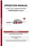
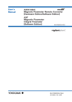
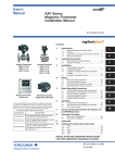
4. WIRING
AXFA14
PULSE OUT
AXFA14
This output cannot switch an AC load. To switch
an AC load, an intermediate relay must be
inserted as shown in Figure 4.4.11.
*The alarm output operates from open (normal)
to closed (alarm occurrence) in the default value
(as setup upon plant shipment). Changes can
be made via the parameter settings.
Protective diode
DO+
Mechanical Counter
DO-
DO+
PULSE OUT
DO-
Load
Electronic Counter
Output voltage: 24 V DC 20%
• Current: 150 mA or less
Pulse rate: 0.0001 to 2 pps
Pulse width: 20, 33, 50, 100 ms
AXFA14
Load
F0417.EPS
Figure 4.4.9
Protective diode
DO+ (or DIO+)
DO- (or DIO-)
Active Pulse Output Connection (Optional
code EM)
This connection is not possible.
Status Input
AXFA14
DO+ (or DIO+)
Relay
Electromagnetic
valve
DO- (or DIO-)
IMPORTANT
External power supply
30V DC, 0.2A. max
Status inputs are designed for use with novoltage (dry) contacts. Be careful not to connect
the status to any signal source carrying voltage.
Applying voltage may damage the input circuit.
AC power supply
F0419.EPS
Figure 4.4.11 Status Output/Alarm Output Connection
NOTE
For status and alarm outputs from the DO or
DIO terminals, parameters must be set. Refer to
“Chapter 6: Parameter Description” in this
manual.
Closed: Less than 200 Ω
Open: More than 100 kΩ
DIO+
AXFA14
DIO-
4.4.8
No-voltage status input
Installing the Cover
Install the cover to the flowmeter by turning it in the
direction of the arrow as shown below. Tighten cover
locking screw 2 counterclockwise using a hexagonal
wrench (nominal size 3 mm) to lock the cover.
F0418.EPS
Figure 4.4.10 Status Input Connection
NOTE
For status input to the DIO terminals, parameters
must be set. Refer to “Chapter 6: Parameter
Description” in this manual.
Status Output / Alarm Output
Cover locking
screws
IMPORTANT
Since this is an isolated transistor output, be
careful of voltage and polarity when wiring. Do
not apply a voltage larger than 30V DC or a
current larger than 0.2A in order to prevent
damage to the instrument.
F0420.EPS
Figure 4.4.12 Installing the Terminal Box Cover
4-8
IM 01E20C02-01E