1
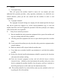
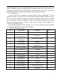
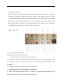
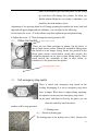
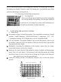
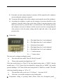
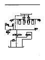
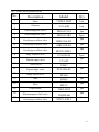
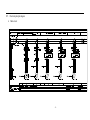
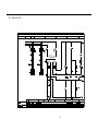
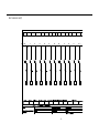
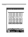
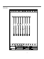
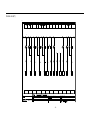
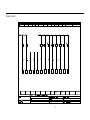
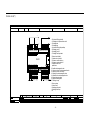
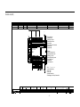
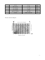
OPERATION MANUAL
SHORT CYCLE LAMINATION PRESS
WINTER SOLID TA series
WARNING!
The operator must thoroughly read this manual before operation.
Keep this manual for future reference.
Henrik Winter Holztechnik GmbH
Druckereistr. 8
04159 Leipzig
Tel: +49 (0)341/ 4619021 Fax: +49 (0)341/4618358 Funk: +49 (0)171/2820443
Em@il: [email protected] Internet: www.winter-holztechnik.de
I.
Manual
i.
User manual using
Who will operate this machine should be master the user manual, and must
understand the operation procedure, safety operation, maintenance etc which this user
manual introduce, please put the user manual near the machine in order to read
expediently.
ii. Copyright of manual
The copyright of manual belongs our company all, this manual provides the buyer
only and its operate the employee use, all the content prohibition copy, or issue and
another form delive and read. If against the personnel of anti these principle, our company
will to find out who was responsible
II.
Safety device and safety measures
i.
Must be installed the safety protection equipment before operate the machine and
may sure working under the safety condition.
ii. All safety protection equipment can’t move or open when the power have not shut
down.
iii. Can be operate the machine just only when this safety protection equipment under
normal condition.
iv. Make sure nobody will be injured when the machine start.
v. Every light error or mistake should be pay attention to it, and check the machine
carefully.
vi. Refer to the electrical install and maintenance should be operate by the electrician
who master the machine working.
vii. Check the electrical equipment on time, and teal with the loosen or broken
electrical in time,forbided to check and maintain the machine with power. when
check or maintain the machine should be close the power, and leave somebody to
check the general power switch, make sure the maintain-man safety.
viii. This machine should be lay on the falt floor make sure the worktable on the level
to prolong the life of the machine.
-1-
III.
Mark and warn the language of the safety
The warning language of this mark means to request the user
while operating this machine bed must provision obeying
up ,the words that neglect will cause human body hurt .
This mark means the temperature to is very high after heating,
can’t touch directly, otherwise will be burned .
This mark means at press the plank press toMat match, can’t
the handle knob put into, otherwise will be pressed the wound.
This mark means when the machine switch on the electricity
don’t open that part, otherwise get an electric shock.
This mark means while opening the machine pay attention to safety, otherwise will
cause the accident trouble.
IV.
Main using and feature
i. Model of machine
This machine is suitable for middle furniture or small man-made board, secondary
process to use hot adhere the furniture board, building separation board, wooden door (that
-2-
man-made plywood and every kinds man-made adhere) Such as plywood, MDF, the
surface decoration material of shaving board: decoration cloth, fine board, metal screen,
man-made and natural plywood, natural sheet, conjoin flower. It also can be drying and
flating the single board, flating and finalizing color decoration wood chip.
ii. Main feature
On the outside of the machine to compose blank, feeding, discharging. The max
limitation to reduce the flaw because of man-made decoration to make rift and overlap .It
also can safety the different description workpiece to lamination with two faces, especially
for the workpeice. It also has advantage of high hot pressing temperature, hot pressing
time short, feeding quick etc. In order to make sure the quality of the workpiece and
improve the working efficiency.
The adjustable parameter of the machines is very wide. Control procedure reasonable
to satisfy the requirement of every kinds lamination.
V.
Main technology parameter
No.
Description
Parameter
Note
1
4
Max pressure
Opening between
pressing boards
Pressing board
dimension
Closed speed
5
Q.ty of cylinder
6
DIA of oil cylinder
60mm/s
Main cylinder 15pcs, fleetness
cylinder 2pcs
15-Φ90mm 2-Φ85mm
7
Oil cylinder travel
350mm
8
Max pressure index
20mPa
9
Hydraulic power
5.5kw
10
Driving power
1-4kw 1-2.2kw 2-0.75kw
11
Heating power
72kw
12
Driving speed
20m/min
13
Max temperature
120°
14
Overall Dimension
13600x2500x2450mm
15
Weight of machine
20660kg
2
3
200t
300mm
4000x1800X65mm
-3-
VI.
Outline diagram of machine
C
D
A-Main body
B-Electreic box
A
C-Belt out-feed fram
B
D---Belt r feeding fram
-4-
C
VII.
Structure of machinery
i.
Body structure
The machinery is compose of body board–pressing, hydraulic pressing, heating and
electric parts, pusher section etc. The body is made of soldered standard material with
nice appearance compact structure and good tension.
ii. Board pressing structure
All board are solid, and the oil holes inside the board are formed by drilling deeply with
good leakage proof and pressure durability both sides of board are well polished by flat
grinder to ensure the stamped work piece flat smooth .Both two direction under the
worktable are furnished with synchronized geared bar to keep the pressing board stable
when it moves up and down.
iii. Feeding-in section
The feeding section is compose of Feeding frame, feeding belt, driving roller and
reduce motor. Feeding frame is welded by the strong enough steel .It is install the 10mm
MDF on the surface of feeding frame .It is avoid the feeding belt attrition with the metal
surface and effect the lift of the feeding belt. The feeding belt is made with the imported
high quality PVC material which is 4mm thickness .Its surface is green, inside is net which
to avoid the roller smooth .It has the endrue to mill and prelong advances. The driving
roller is made with the thickness enough to made. It is very strong and same the center.
The reduce motor is made by TaiWan .The power is 0.75Kw. rate is 1:20 .
iv. Pressing board feeding section
The pressing board feeding section is to send workpiece which receive from feeding frame
into the presses machine and send out the workpiece which finish procedure .It is compose
of High model, driving roller, reduce motor. To made the high temperature model cycle
driving, It is endure the high temperature and milling.
v. Feeding-out section
It is compose of feeding frame, driving belt and reduce motor .The front 15 pc roller
mainly driving the reduce motor. and the feeding section is reduce the labor in order to
improve the working effective.
-5-
vi. Hydraulic section
The hydraulic press system consists of oil-tank, pump oil –cylinder and hydraulic
Press control valve .the turbo pump is used to control the oil current and the piston pump is
used to control the oil current and the piston pump is used to transmit oil and start press,
the hydraulic press pump is driven by an engine to transmit oil and start press and the
hydraulic press control valve is with compact structure stable functions in the hydraulic
press system the current valve control the max pressure which acts as a safety protection
unit to protect the oil pump against over-loaded pressure of the machinery .The single
current reserving valve makes the board produce anti-pressure for the purpose of reserving
to keep the machinery moving stability. The pressure meter is for displaying the pressure
valve.
1
2
7
3
8
4
9
5
6
10
1——oil pump :provide to the hydraulic system
2——Motor:Drive the low flow gear wheel and high flow impeller pump
3——electromagnetic vavle :For control the rise up and down
4,6—Liquid vavle:To provide the oil for the system quickly
5——Check valve :To unload the high pressure
7——Eletromaganetic valve
8——Flow vavle
9——Electtromagnetic ball valve
10——Hydraulic single vavle
-6-
vii. Electric structure
The electricity part consists of main circuit and control circuit, the main circuit contains
a current breaking unit which protects the whole circuit against overload or short
–circuit the alternating current unit and heat-relay unit protect the whole circuit against
low-load and overload. The control circuit consists of alarm thermomater control panel
pressure board hold –pressure timer and control button .The whole circuit is designed
reasonably with characteristics of safety and easy of peration.
A. Control panel
1—Power indication: This lamp
bright means has connected with power.
2--alarm: when you hear alarm ,platen will rise up.
3—Manual/Automatic button: Choose this hand move button, every step operation should
be operate by operator, Choose the auto button, every moving of the machine auto
operating.
4—oil pump start button: press this button, oil pump start.
5—oil pump stop button: press this button, oil pump stop.
6—Timer: The timer means will show the workpiece tighen to the setting pressure .the
hold pressure meter will start timing and show the digists.
-7-
7-lower button: Press this button, the pressing board lowering.
8—Raise button: Press this button the pressing board rising.
9—Material out button: Press this button, the feeding belt will be send out the workpiece
which after procedured.
10—Feeding button: Press this button, the lamp bright, workpiece send into presses.
11—Emergency stop button: Press this button all the moving will be stop
12—Automatic start button: Choose this auto switch and press this button the machine
start auto.
13—Heating start button: Press this button, lamp bright, heating board start heating,
14—Hot oil pump start button: Press this button, hot oil pump start.
15—Heating stop button: Press this button, heating stop.
16—Heat oil pump stop button: Press this button, oil pump stop.
17—Temperature controller: This temperature show the temperature which after heating,
in order to keep the temperature.
B. Case
-8-
1------Switching
power
supply:
Provide
direct
current
of
the
electromagnetic valve.
2——Intermediate relay, to control the communication contactor heating .
3——Time relay, feeding time adjustment
4------ Time relay: adjust the time of release of pressure
5----- Phase sequence protector:For the phase error, phase lack protection
of power supply
6--------insurance
tube
:
To
protect
the
24v
voltage
short-circuit over
current ,control circuit and electromagnetic valve.
7------ Circuit breaker: control feeding frame and the short circuit protection
8—— Control transformer: For Isolation control and step-down
9—— Inverter: used to control the mainframe out-feeding
10—— Inverter: used to control the front belt conveyor feeding frame
11——Inverter: after used to control the out-feed frame
12-----Programmer: used to control the system programming
13-----Breaker: control of hot oil pump and the short circuit protection
14——Breaker: control of oil pump and the short circuit protection
15,16,17---Breaker: control the heating system of three group.(each of heating group
heating power is 24kw)
18------Communication
contactor:used
to
control
the
mainframe out-feeding
19------ Communication contactor: used to control the belt converoy feeding
frame.
20------ Communication contactor: used to control the out-feed frame
21——Communication contactor: used to control the hot oil pump.
-9-
21a——Thermal relay: used to protect the hot oil pump motor overcurrent
and over load
22—— Communication contactor: used to control the oil pump
22a——Thermal relay: used to protect the hot oil pump motor overcurrent
and over load
23------- Communication contactor: to control the heating group 1
24------- Communication contactor: to control the heating group 2
25------- Communication contactor: to control the heating group 3
VIII. Loading and transportation g of machine
i.
Transportation
When transport must be fixed the machine firmly, make the pressing section under the
tighten condition (the tighten pressure is about 2-5 Mpa) do the prevent shine and rain
measure. When loading should be operate by the professional
ii. Transport and stock environment requirement: Transport and stock should be
during -25℃ ~55℃ .If Under more than 55℃ but less than 70 ℃ environment, the
machine can not working over 24 hours
iii. Loading
1). When loading the machine should be evacuate people and set the safety protection
2). Use the crane or electrical forklift which weight enough to loading the machine.
During the whole loading procedure should be make sure the machine is steady,
when the machine lifting, forbidden around anyone (The right picture is the forklift
loading)
iv. After loading put away all the safety device loading tool and temporary device
IX.
Some parts description of machine
i. Timer
There are three kinds of set for opion (hour “H” minute “M” second
“S” )on the digital pressure –holding timer ,the operator may select
according to practical requirements .when you select “H” you may
adjust the button to “H” then use your hand to press the small touch
button (the button marked “-”means drcrease the value , “+”means
increase the value )on the pre-set digital switch and setthe needed
- 10 -
time you can set “minute” or “second” in the same way (Notes:The time of this timer
range from 0.01second to 99hours and 99minutes.
ii. Temperature controller
iii. Temperature controller
There is a “temperature screen ”A on the up right side of
A
The temperature controller, the low side is the button of
SET(Confirm button )up and down button
A— set key
B— choice key
C— “+”key
D— “-”key
Setting temperature of pressing board
Press the SET key“1” over 5s the parameter enter into the
1
2 3
4
procedure and will be reback after finish. Press SET key, the
unit value will be twist, at that time you can modify with the
Key “3”or “4”,press the SET key to confirm and back to the normal .If pass 20 seconds
still no moving, it will reback to the normal (Note: Press the SET key over 5s it will
enter the parameter directly to the operation procedure then reback auto.)
iv. Pressure meter connector
1—pressure setting indicator
2—system pressure indicator
3—setting button for pressure
The meter is used to the pressure and indicate the system
pressure, before start to operate this machine, must firstly press
down the setting system working pressure for actual needing.
v. Balance device of pressing board
A——Gear strip tighten screw
B——Balance gear strip
C——Bearing seat
For the baalane device of platens is compose of lengthwide and
transverse .It is use for keep the platens balance when liftign
up .When the gear strip and gear wheel milling or loose ,gear
- 11 -
wheel will match the gear strip and palten can not lifting
up even more will damage the cylinder .So when you
find the platens lifting not very steady or unbalance ,you
should be check the balance device
Adjustment of low pressing board level: During operating the machine the front, back and
right and left appear height and low unbalance, you can adjust as the following:
a.First loosen the screw “A”on the balance strip then tighten the pressing board rising .
b.Tighten the screw “A” Then downing the pressing board is OK .
(1)、 Platen limit switch
up limit stroke switch
There are two limit switches of platen. On the above is
the up limit stroke switch: When the worktable lifting meet
this switch,it is no longer rising; In the low position is the
down limit stroke switch,before touch this switch ,the
worktable depends on its own weight falling fastly ,Once
touch switch, the worktable is start to slow down, so
conducive to the protection the platen.
lower limit stroke switch
(2)、 Pull emergency stop switch
There is install cord emergency stop switch on the
feeding, discharging, It is use to emergency stop when
there is danger. When there is danger during operating,
the operator can not press the emergency stop switch
on the panel with hand or far away the panel, you can
draw this switch by hand, the whole
machine will be stop operation.
⑶ Heating case
A——Electricity heating pipe
The heating pipe of the heating case is 6Kw ,Because the
- 12 -
layers is different the quantity of the heating pipe is different .The heating pipe is install on
the heating case directly .If need to replace the heating pipe ,you should be shut off the
general switch and give out the guide oil .
⑷ Connecting of channel and pressing board
A——Pressing board
There is one oil inlet and oil intake on every layer, among that
the soft pipe and the corresponding oil in iron pipe connected
Cone
into
T
Mpa
Pressure Conversion Diagram
220
200
0
1
cm
4.
3
2
3
/
kg
160
m
/c
g
m
/c
6k
3. .1kg
cm
3
kg/
2.6
cm
kg/
2.1
cm
kg/
1.6
g/cm
k
4
1.
g/cm
1.1k
/cm
0.8kg
cm
k
5
.
0 g/
0.3kg/cm
4
Workpiece Area M
5
6
140
120
100
80
60
Relative working Pressure
180
kg/
cm
6.
7k
g/
cm
5.
3k
g/
cm
E.
m
D.
9.5
C.
i. Install debug
Environment required of install the machine: The requirement environment of install
machine: 1.Install dimension: 13600x2500x2450mm 2. temperature: -10°C~55°C
3.Atmosphere humidity :85% 4.Height above sea level: hereinafter1000M.
Lay out of machine: The machine should be lay out on the flat concrete. After lay out
the machine, adjust the level of the machine to make sure the front ,back ,right and left
four point on the same height
Distribution: According the distribution of the required, connect into the voltage,
current and frequency on the power terminal.
Make sure the correct direction of the hydraulic system oil cylinder and heating pump
motor: Press the raise button, if the pressing board rising that means the rotating
direction of motor is correct, if not you have to change any tow phase wises during the
three phases wises to get the correct direction.
Setting the working pressure: According the workpiece area, to check the relative
pressure
kg/c
B.
Install, debug and operation of machine
14.3
A.
to make the oil cycle during the pressing board and heating case
to keep the pressing board constant temperature.
Pressure Gauge Setting
X.
Come
back
40
20
7
- 13 -
ii. First make sure how many intensity of pressure will be required on the workpiece
area according the workpiece required.
iii. To measure the length, wide of the workpiece and count the area of the workpiece
iv. According the workpiece to make sure the intensity of pressure should be on the
workpiece, from the relative line on the chart (If there is not any intensity on the
chart you can draw by yourself) there is an intersection of the intensity pressure
and workpiece area anis of ordinate. and the crosswise axis line corresponding left
value pressure is the red pointer setting, and the right side value is the general
pressure value.
F. Setting time
A——The digital from 0 to 9 can be adjusted
B——The digital from 0 to 9 can be adjusted
G
F
A BC
D
E
C——Selection of time model
D——The digital from 0 to 9 can be adjusted
E——The digital from 0 to 9 can be adjusted
F——“+”means increase
G——“-”means reduce
The time can be setting according the actual
a.
First select the time model “Hour H, Min M, Second S”
b.
Then set the required four digital from “0-9”
If the time model choose as “Hour H “the four digital setting value is “99H99”, that the
actually time is “99.99” hour, if the four digital key setting value as “00H03” the actually
pressure holding is “0.03”hour (If the time setting model is “Min M or second S”The back
value hour should be change as “ M” or “S”
c.
The time Max value can be set to “99.99 hour ”,the min is 0.01S
d.
After time, you send the workpiece to the feeding table
G. Temperature setting of pressing board (Please check the description point2
- 14 -
temperature controller)
H. Workpiece layout
Before add the pressure on the workpiece ,you should be choose the correct layout place
according the actually dimension ,Forbidden add the pressure on the workpiece when the
right left and front ,black unbalance
1. Workpiece layout wrong sketch map
Note:Anyway how many layer of the machine Every layer forbidden to working
the workpiece with unbalance or will be damage the machine seriously .
- 15 -
2.Workpiece layout correct sketch map
Note:Every layer has to lay out the workpiece with the correct position.
- 16 -
ii. Operation
A. Safety checking before operate the machine
Before operate the machine must be check once of the machine carefully to make sure
operation safety
a.
Check every safety protection device correct, firmly or not
b.
Check every rotating, connection section firmly or not
c.
Check the hydraulic system pressure normal or not
d.
Check the oil pump, hot oil pump rotating normal or not
e.
Check the pressing board raising steady, firmly or not
f.
At last operate the machine without anything and check the whole procedure
correct or not.
B. Manual operation
1.Connet power ,power lamp “1”
bright
2. According the size of the
workpiece and the requirement of
craftwork to set the suitable
pressure,and setting the time on
the pressure meter “A”
3. Timer “6” to adjust the timer
4. Press again the heating start button“13” ,that will show the actual temperature “6”
on the platen
5. When attain the setted temperature ,please lay the workpiece with correct
direction .
6. Press the rise up button “8” platen will rise up
7. When the platen attain the setting pressure ,Timer “6” will start to timing
8. After time ,platen will open auatomaticly (Also can press the button “2” to open the
platens)
- 17 -
C. Automatic operation
When choose automatic switch, the workpiece must be to the photoelectric
position to block the light, click on the "8" automatic start, the feeding frame
began to feed. When all workpieces be transmission to the press by
conveyor belt .low table start rise up and and pressure to the set pressure,
the timer is starting timing, when to set the time after the platen automatic
falling, falling meet stroke switch an automatic operation procedure is
completed
XI. Failure and solution
When checking the machine you find the failure as the following ,you can deal with it as
the following solution at first .If follow the solution also can not solute the problem,please
assist from manufacturer
Failure
Reason
Solution
General power or control
Open the power
power closed
Power short of phase
Check and repair
Open the electricity case and close the
Breaker can not close
breaker
The connector does not Check the circuit whether break or
Press the button but work or hot relay break
overload and repair
machine can not operate
Hydraulic system control
electromagnetic
valve Replace the electromagnetic valve
break
Pressure meter connected
point can not touch very Check and repair
well
The Mid relay break
Replace the mid relay
Check the motor isolation qualify or
Short circuit or breaker
not .and whether connect the earth
Suddenly short of power trip
wires or not close the breaker
when the machine
working normal
Overload to make the hot Check the circuit and adjust the hot
relay short circuit
relay recover
The motor start but can
not raise the pressure
Oil pump break
Replace the oil pump
and the noise from oil
pump is very lound
Oil pipe leakage
Tigthen or replace the connector
Liquid is very low
Add oil to the normal liquid
Oil liquid make the air
The mode of hydraulic oil
Replace the suitable hydraulic oil
is wrong
Oil pump heating or no Oil pump damage
repair or replace the oil pump
- 18 -
enough pressure
There is dirty inside the
Clean ,repair or replace overflow valve
overflow valve
Pump motor does not
Power short of phase
rotating
Check the three phase of voltage
Check the electrical circuit,if it no
The oil leakage form the Loading circuit can not
problem ,please repair or replace the
high side to the low
move
exchange vavle
XII.
Maintenance of machine
i. Daily maintenance
A. Keep the machine clean, keep every driving section and connect section lubricant.
B. Forbidden to put anything on the machine.
C. Check the oil condition into the oil case every week and add in time.
D. Check the oil circuit leakage or not and repair in time every day.
E. Check the valve and pole and the screw on the pressing board loosen or not every
day, if loosen fixed in time.
F. Check the lifting balance gear wheel and strip on the pressing board using condition
every day.
ii. Maintenance during operating
A. Operate the machine correctly, forbidden working over the original designed
working range.
B. Put the workpiece correctly, forbidden dislocate.
iii. Check the machine every week
A. Before operate, please check every driving section and safely device correct or not,
and operate the machine without anything, in order to check every moving correct or
not.
B. Check every month, and especial check every fitting and other limit switch using
condition lubrication etc, and check the safely protection fitting irmly or not and
adjust and replace.
C. Check the oil cylinder, oil and hydraulic system using condition, especially for the
oil whether need to replace, the oil circuit whether leakage oil condition, the pressure
normal or not of the system.
iv. Maintenance when stock the machine
A. When you do not want to use the machine, please clean it and add lubricant on every
driving section and package the machine.
B. Put the machine on the dry place and avoid to shine directly.
- 19 -
v. Selection of hydraulic :ISO-VG68# resist milling hydraulic oil
Or model: HF-2 46# resist milling hydraulic oil
DTE 26 resist milling hydraulic oil
Caltex: rando Hd 68 resist milling hydraulic oil
Esso: nuto H68 resist milling hydraulic oil
Shell: Tellus oil 68 resist milling hydraulic oil
vi. Guided heating oil opl:N32 or Caltex :Texatherm 32 guided heating oil
vii. Lubricant of balance gear wheel: the common bearing oil fat or Caltex :Meropa 68
lubricant fat .
- 20 -
XIII. Hydraulic principle diagram
4
- 21 -
XIV. Detail list of hydraulic device
No.
Description
Model
Q.ty
Motor
2
7.5HP-5.5KW
1set
Oil pump
3
V23-A3R
1set
Electromagnetic valve
4
DSG-03-3C4
1pc
Electromagnetic valve
5
DSG-03-2B2
Overlying overflow valve
6
MRV-03A-K3
2pcs
1pc
Overlying overflow valve
7
MRV-03P-K3
Overlying overflow valve
8
MTCV-03W-1
Single sequence valve
9
CV-03G-50
Tubular single valve
10
CV-04T
check valve
11
V2067
Liquid single valve
12
PCV-03G-05
Surge check valve
13
PF100
Oiler
14
QUQ2
Filter
15
MF-12
Liquid meter
16
YWZ-100T
Electromagnetic ball valve
23QDF-6B
Overlying overflow valve
MTCV-03B-1
1
17
1pc
1pc
2pcs
1pc
1pc
1pc
1pc
1pc
1pc
1pc
1pc
1pc
- 22 -
XV.
i.
Electrical principle diagram
Main circuit
~
S
.
2
2
5.4
3
2
3
3
4
4
4
5
5
5
2
出料电机变频器
送料电机变频器
2
~
2
2
~
3
3
3
~
后出料电机变频器
3
3
~
3
~
:
:
:
:
:
:
:2012.05.03
:
1:
- 23 -
ii. Control circuit(1)
文件名: 快速贴热压机
3.0V
.
2
2
5.4
2
7
BK300VA 380V
+
-
:
:
:
:
:
:
:2012.05.03
:
2:
- 24 -
iii. Control circuit(2)
TONGAN
24+
P
5.0
PLC L+
13.0
SB1
I0.0
SB2
SB4
SB3
I0.1
I0.2
I0.3
SA
SB5
I0.4
SB7
SB6
I0.5
I0.6
SB9
SB8
I0.7
I1.0
SB10
I1.1
I1.2
:
:
:
:
:
:2012.05.03
:
:
- 25 -
7
SB11
I1.3
iv. Control circuit(3)
TONGAN
P
24+
5.0
6.0
PLC L+
KT1
I1.4
SB12
WJ1
I1.5
I2.0
WJ2
I2.1
SF1
I2.2
SA
SB6
I2.3
KT2
I2.4
KT3
I2.5
I2.6
I2.7
:
:
:
:
:
:2012.05.03
:
- 26 -
:
7
Control circuit(4)
TONGAN
P
5.0
PLC L+
SQ1
I3.0
SQ2
SP
I3.1
I3.2
SP
I3.3
SQ3
I3.4
I3.5
I3.6
I3.9
:
:
:
:
:
:2012.05.03
:
:
- 27 -
7
Control circuit(5)
TONGAN
0 V
11.0
8.0
HL1
Q0.0
HL2
KM1
Q0.1
YU1
HL3
Q0.2
KM3
Q0.3
HL4
KM4
Q0.4
KM5
Q0.5
KT1
HL5
Q0.6
Q0.7
HL6
Q1.0
Q1.1
HL7
Q2.0
Q2.1
:
:
:
:
:
:2012.05.03
:
:
- 28 -
7
SQ1
KM2
Q2.2
Control circuit(6)
TONGAN
0 V
5
24V DC 0V
9.0
8.0
KA
Q2.3
WJ1
Q2.4
YU2
Q2.5
Q2.6
Q2.7
Q3.0
YU3
Q3.1
KT2
Q3.2
YU4
YU5
Q3.3
Q3.4
YU6
Q3.5
YU7
KT3
Q3.5
Q3.5
:
:
:
:
:
:2012.05.03
:
:
- 29 -
7
Control circuit(7)
文件名: 快速贴热压机
同安
red
2
11.1
9.1
24VAC
24VDC
0
11.0
KM2
80
81
82
KA
83
84
85
86
87
EM223
9.0
90
91
92
93
94
95
96
97
40-hydraulic lifting photocell
41-feeding motor photocell auto valid
42-heating start
43-heating stop
44-hydraulic lifting table pedal up
45-heating group 1
46-heating group 2
47-feeding frame spot start
50-down travel limited
51-platen rise up limited
52-pressure meter switch on
53-pressure meter switch off
54-sped reduce valve
pedal down
90-public electromagnetic valve
91-pressure unload 1 electromagnetic valve
92-pressure unload time relay
93-platen lift up electromagnetic valve
94-plate lift down electromagnetic valve
95-speed reduceing valve
96-pressure adding valve
97-feeding in relay
80-rise up lamp
81-down lamp
82-heating pump start
83-heating start lamp
84-
:
:short-cycle lamination hot press twice circuit I/o
:
wrining
: draw
:
:
:2012.05.03
:
:
- 30 -
Control circuit(8)
同安
文件名: 快速贴热压机
同安
文件名: 快速贴热压机
11.1
2
12.0 12.1
N
4
11.0 0
红色
KM1
60
61
KM3
KM4
62 63
64
20-rise up button
21-down button
22-feeding in button
23-feeding out button
24-automatic
25-manual/auto shift buttonh
26-pump start
27-pump stop
KM5
65
67
66
68
70
CPU224
RLY
SB1
SB2
20
SB3
21
60-alarm
61-main oil pump motor
62-push pneumatic valve
63-feeding in motor
64-main bldy feeding motor
65-out feed motor
66-digital time
67-auto indication
SB4
22
B9
23
24
25
26
B10 SB11
KT
27
M
P
30-hot oil pump start
31-hot oil pump stop
32-hot start
33-hot stop
34-digital time delay
35-emergency button pull wire switch
:
:short-cycle lamination hot press twice circuit I/o
:
:
wrining
: draw
:
:2012.05.03
:
9:
- 31 -
XVI. Detail list of electrical device
NO
1
2
3
4
5
6
7
8
9
10
11
12
13
14
15
16
17
18
19
20
21
22
23
24
25
26
27
28
29
30
31
MODEL
Q.ty
AC connector
2510 24VAC
1pc
AC connector
0910 24VAC
4pcs
Hot relay
JRS09-25 18A
1pc
Hot relay
JRS09-25 10A
1pc
AC connector
SP-40 40A24VAC
2pcs
AC connector
SP-60 60A 24VAC
1pc
Travel switch
4pcs
8108
Red button
LA39-01
3pcs
Green button with lamp
LA39101 24VAC
8pcs
Emergency stop
LA39101
1pc
Shift switch
LA39
1pc
AP-22 24VAC
1pc
Power start indication
S-145-24
Power switch
1pc
DHC 32A
1pc
Air switch
DHC 40A
3pcs
Air switch
DHC 60A
1pc
Air switch
RT18-32 4A
3pcs
Fuse seat
2 meter
1pc
thermocouple
Temperature adjuster
1pc
WZA50-300℃
Temperature
AZ208 24VAC
1pc
Digital time relay
PH48SH 24VAC
1pc
BK380 415/220 24
Control transformer
1pc
C220V=180VA 24V=120VA
24VAC
1pc
Mid relay
40A
1pc
Combinate switch
E3JK
2pcs
Photoelectricity switch
Pull switch
1pc
220V
1pc
fan
1pc
filter
150pcs
Wring board
UT2 2.5 ㎡
100A 3P
1pc
Wring board
60A 3P
2pcs
Wring board
Description
- 32 -
32
33
34
35
36
37
2.5 ㎡
2.5 ㎡
13 15A
5 10A
ZP 10A
CBZ-30 24VAC
Fixed
End plate
Air plugs
Air plugs
Guide socket
Alarm
8pcs
4pcs
5pcs
2pcs
1pc
1pc
Pressure conversion diagram
T
Mpa
Pressure Conversion Diagram
220
200
cm
g/
3k
cm
g/
cm
2
5.
7k
6.
kg/
m
1
9.5
14.3
kg/c
Pressure Gauge Setting
0
4.
3
3k
160
cm
g/
cm
6k
g/
1k
.
cm
3
kg/
2.6
cm
kg/
2.1
cm
kg/
1.6
g/cm
k
4
1.
g/cm
.
1 1k
/cm
0.8kg
cm
k
5
0. g/
0.3kg/cm
140
3.
4
5
6
120
100
80
60
Relative working Pressure
180
m
c
g/
40
20
7
Workpiece Area M
- 33 -


![Télécharger Pdf [3 890 Ko] - Groupement pour l`Amélioration de l](http://vs1.manualzilla.com/store/data/006453454_1-f2b09e64f4cbbe4159e9eda196b950b9-150x150.png)