1
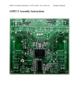
RTCU Emulator - User's manual
Version 1.02
© 2015 Logic IO, www.logicio.com
®
2
Table of Contents
1.
RTCU Emulator
3
1.1
Limitations ........................................................................................................................... 5
1.2
Command line arguments .................................................................................................. 6
1.3
Control Panel ....................................................................................................................... 7
1.3.1
Menu Items ................................................................................................................. 10
1.3.2
Devices ........................................................................................................................ 10
1.4
Modules ............................................................................................................................. 12
1.4.1
Core ............................................................................................................................. 12
1.4.1.1
1.4.1.2
1.4.1.3
1.4.1.4
1.4.2
Debug Messages ............................................................................................................................................ 13
IO ...................................................................................................................................................................... 13
Memory ........................................................................................................................................................... 15
Power Management ...................................................................................................................................... 16
Data ............................................................................................................................. 17
1.4.2.1
1.4.2.2
1.4.2.3
1.4.3
Datalogger ...................................................................................................................................................... 18
File System ...................................................................................................................................................... 19
Persistent Data .............................................................................................................................................. 21
Communication ........................................................................................................... 22
1.4.3.1
1.4.3.2
1.4.3.3
1.4.3.4
1.4.3.5
1.4.3.6
1.4.3.7
1.4.3.7.1
1.4.3.7.2
1.4.3.7.3
1.4.4
1.4.4.1
1.4.4.2
1.4.4.3
1.4.4.4
1.4.4.5
2.
1-Wire ............................................................................................................................................................. 23
CAN ................................................................................................................................................................... 24
Display ............................................................................................................................................................ 26
GSM .................................................................................................................................................................. 26
Network ........................................................................................................................................................... 31
RF ...................................................................................................................................................................... 33
Serial Ports ..................................................................................................................................................... 35
Physical Serial Ports .............................................................................................................................. 35
Virtual Serial Ports ................................................................................................................................. 36
Virtual MDT .............................................................................................................................................. 37
Sensors ........................................................................................................................ 38
Accelerometer/Vibration ............................................................................................................................. 38
GPS ................................................................................................................................................................... 40
Intrusion ......................................................................................................................................................... 42
Real Time Clock ............................................................................................................................................. 42
Temperature ................................................................................................................................................... 43
Using the RTCU Emulator from the RTCU IDE
RTCU Emulator - User's manual
44
© 2015 Logic IO, www.logicio.com
RTCU Emulator
4
RTCU Emulator
1
RTCU Emulator
Welcome to the RTCU Emulator!
The RTCU Emulator allow a program to be tested in detail on a PC with a high confidence that it will
behave exactly the same way in a physical RTCU device.
As each RTCU variant is emulated and almost all hardware features are available there is very few cases
where a physical device is required in the complete development phase of an application.
The RTCU Emulator is based on the same source code as the actual firmware, so even possible bugs in
the firmware will also be present in the RTCU Emulator.
The RTCU Emulator can be used stand-alone or it can be started directly from within the RTCU IDE.
The Emulator starts up with the main window, the Control Panel.
From the Control Panel, the rest of the windows can be opened, e.g. the GSM and IO windows, as
shown above.
RTCU Emulator - User's manual
© 2015 Logic IO, www.logicio.com
5
RTCU Emulator
1.1
Limitations
The RTCU Emulator offers a very precise and comprehensive emulation of the physical RTCU devices,
but still there are some limitations implied:
·
·
·
·
·
·
·
·
·
·
·
·
·
·
·
The timing of the individual operation may vary compared to the physical device.
The buzzer does not support different frequencies.
Generic 1-wire is not supported.
RFBC packets must be manually created, using the sender and receiver fields as raw data.
The batConsumption functions are not supported.
gsmModemMode is not supported and will return 2.
gsmNetworkTime is not supported.
gsmHeadset is not supported and will return FALSE when called.
gsmHandsfree is not supported and will return 5, on devices normally supporting this.
Bluetooth is not supported.
Adding options are not supported, the devices are already fully upgraded.
xVoice is not supported.
The GPRS monitor can be configured but does not perform recovery on the connection.
Direct cable connection to the RTCU IDE can only be established using the alternative service port.
Device fault-mode is not supported. A fault will show a message with the corresponding fault and the
emulator will stop.
Some of the above limitations are scheduled to be eliminated in future releases.
RTCU Emulator - User's manual
© 2015 Logic IO, www.logicio.com
6
RTCU Emulator
1.2
Command line arguments
The emulator cam be started from the command line like this:
RTCUEmulator.exe [options] <Project file>
<Project file> is the path to the project or the application files(.prj, .rpc or .vsx) to open from the start.
The available options are as follows:
-p <port
The TCP/IP port to start listening on for commands. Used by the IDE to load the
number>
current project.
-d <serial
The serial number of the device to load.
number>
-m
Start minimized
RTCU Emulator - User's manual
© 2015 Logic IO, www.logicio.com
7
RTCU Emulator
1.3
Control Panel
The control panel is the main window of the emulator. It controls which project to run, which device to run
it on and controls which other windows to show.
On the initial start and when no device is loaded, it looks like this:
To load a device, click on the Devices... menu item.
When a device is loaded, the control panel looks like this:
RTCU Emulator - User's manual
© 2015 Logic IO, www.logicio.com
RTCU Emulator
8
Menu items
Used to configure the emulator.
RTCU Emulator - User's manual
© 2015 Logic IO, www.logicio.com
9
RTCU Emulator
Device information
The device information panel shows the type, serial number and type of the emulated device, as well as
the possible name of a loaded application.
Supported modules
This lists the available modules, sorted by area.
Clicking the button will show the window for the module.
When a button is disabled, no window is needed for this module.
When the gear symbol is available, it can be clicked to bring up the configuration dialog for the module.
Some modules have multiple implementations such as the serial ports. By right clicking on the button, a
menu pops up to select what implementation to use.
Configuration and selection of implementations can only be done while the emulator is stopped.
LEDs and DIP switches
All the LEDs and DIP switches of the physical devices are available.
Execution buttons
The reset button resets the device, as on a physical device.
The halt button halts the execution in the device.
Emulation buttons
The Load & Run button loads the selected project(shown in tooltip) into the device and starts the
emulation.
The Start button is used to start the emulation, without loading the project.
The Stop button is used to stop the emulation.
Only available on Windows 7 and newer:
Hovering over the icon on the task bar shows information about the device in the Emulator.
RTCU Emulator - User's manual
© 2015 Logic IO, www.logicio.com
10
RTCU Emulator
1.3.1
Menu Items
The menu items are used to configure the emulator.
Project
o
o
o
o
Open
Load & Run
Stop execution
Exit
Opens an application.
Loads the application into the device and starts it.
Stops the emulation of the device. The same as pressing the Stop button.
Exits the emulator.
Devices...
Shows the Devices dialog
Window
·
o Reset Layout
1.3.2
Places all the windows next to the control panel.
Devices
This dialog is used to manage the devices.
The list shows the available devices with type, serial number and name.
The active device is marked with italic.
RTCU Emulator - User's manual
© 2015 Logic IO, www.logicio.com
11
RTCU Emulator
The dialog has the following buttons:
New
Create a new device:
The first 3 digits of the serial-number specifies the device type in question and are similar to the
corresponding physical device. The middle 3 digits "999" indicates that this is an emulator, it will never
occur on a physical device.
Finally, the last 3 digits of the serial number can be changed to allow for multiple devices of the same
type.
The name field allows for assigning a descriptive name to the device, to make it easier to recognize.
Load
Closes the active device and loads the selected device. Can also be done by double-clicking on a
device.
Edit
The edit dialog allows for changing the serial number and name of the selected device.
Clone
Creates a new device, using the configuration of the selected device.
Provide the name and serial number of the new device.
Delete
Delete the selected device.
Close
Closes the dialog.
RTCU Emulator - User's manual
© 2015 Logic IO, www.logicio.com
12
RTCU Emulator
1.4
Modules
The different modules have their own windows for managing the emulated hardware.
The modules are sorted by area for a better overview.
· Core
o Debug Messages
o IO
o Memory
o Power Management
· Data
o Data Logger
o File System
o Persistent Data
· Communication
o 1-Wire
o CAN
o Display
o GSM
o Network
o RF
o Serial Ports
· Sensors
o Accelerometer/Vibration
o GPS
o Intrusion
o Real Time Clock
o Temperature
1.4.1
Core
The Core area contains the functionality that is common for all RTCU devices, which does not belong in
other areas.
Modules:
· Debug Messages
· IO
· Memory
· Power Management
RTCU Emulator - User's manual
© 2015 Logic IO, www.logicio.com
13
RTCU Emulator
1.4.1.1
Debug Messages
The Debug Messages window is used to show the debug output from the application.
Clear List
Clears the output.
Save to file...
Saves all the lines to a file.
Copy to clipboard
Copies all the lines to the clipboard.
Use Ctrl+C to copy the selected lines to the clipboard.
1.4.1.2
IO
The IO window allows for controlling the inputs and viewing the outputs of the device and any configured
IO extensions.
RTCU Emulator - User's manual
© 2015 Logic IO, www.logicio.com
14
RTCU Emulator
The list on the left is used to select between the onboard IO and any configured IO extensions.
If a project(.prj file) has been loaded, the configured names from it will be used as names for the IOs,
otherwise the default names will be used.
The red arrows shows the status of the digital inputs. Click on an input to change the state of it.
The green arrows shows the status of the digital outputs.
The value of the analog inputs can be changed on the slider or by entering a number directly.
The analog outputs are shown as a bar, as well as numerically.
For the onboard IOs, additional information is available:
RTCU Emulator - User's manual
© 2015 Logic IO, www.logicio.com
15
RTCU Emulator
The switches show the state of the user switches. Click them to toggle the switch. The switches can
also be controlled from the control panel along with any extra system switches.
The User LEDs show the status of the individual user LEDs. The LEDs are also available on the control
panel along with the system LEDs.
The status of the S0 interface and of the DC-Out external power supplies are shown on supporting
devices.
1.4.1.3
Memory
The "Memory" window is a way of changing or viewing the contents of each memory location.
RTCU Emulator - User's manual
© 2015 Logic IO, www.logicio.com
16
RTCU Emulator
Each page shows 16 memory locations. To change the shown location, change the First index to the
wanted starting location.
To add additional pages, click the "+" symbol, or right-click on a tab and click Add tab. To remove a
page, click on the tab with the middle mouse button, or right-click it and select Close tab.
To change the value at a location, change the value and leave the field or press enter. While the number
is being edited, it will be red. When it has been changed in the device, the text turns black again. If a
memory location is used as a VAR_OUTPUT item, it is not possible to change the value as the program
is overwriting the contents of the memory location with every scan.
1.4.1.4
Power Management
The Power Management window provides access to the power management functions of the device.
RTCU Emulator - User's manual
© 2015 Logic IO, www.logicio.com
17
RTCU Emulator
The label at the top shows the current power state.
Supply
Allows for connecting and removing the external power supplies and adjusting the voltage on the DC
supply.
AC is only available on devices with AC.
Battery
If Battery backup is selected(restart required), the device will use the battery to continue running if no
external power supply is available.
Charger enabled shows if the charger is enabled in the device and Charging shows if the battery is
currently being charged.
The battery level can be seen and adjusted on the slider.
Wake sources
A list of all the available wake sources on the device. When in a power save mode, the active wake
sources are highlighted.
Time
The timeout wake source, with the option to manually wake the device before the interval has elapsed,
especially useful if using a long timeout.
For pmWaitEvent it shows the time until it wakes, for pmPowerDown and zpPowerDown it shows the
time it will wake at.
1.4.2
Data
The Data area contains the functionality that is used to access data in the RTCU device.
Modules:
· Datalogger
· File System
· Persistent Data
RTCU Emulator - User's manual
© 2015 Logic IO, www.logicio.com
18
RTCU Emulator
1.4.2.1
Datalogger
The Datalogger window is used for manipulating the contents of the Datalogger storage in the device.
The "Fetch range" section allows filtering the records fetched.
· "From/To" limits the records to a range determined by a "Start" and "Stop" time.
· "Tag" limits the records to a particular Tag.
The "Clear Log" button empties the Datalogger.
The "Destroy Log" button will completely clear the Datalogger memory, as if the logDestroy function was
called.
The "Save as file" button saves the data in a .CSV file for easy viewing in various spreadsheet programs
etc.
RTCU Emulator - User's manual
© 2015 Logic IO, www.logicio.com
19
RTCU Emulator
1.4.2.2
File System
The file system windows is used to manage the file system.
Media selection
The drop down list allows for selecting the media to show.
Folder tree
The folder tree shows the folders available on the selected media.
Selecting a folder will show its contents in the file list.
Right-clicking on a folder allows for creating and deleting folders, and for formatting the media.
File list
The file list shows the files in the current folder, that matches the active filter.
Right-clicking a file shows a menu allowing for importing, exporting, renaming and removing the selected
file.
Double-clicking on a file opens a dialog to show the contents of the file.
File filter
The file filter allows for filtering files by name. Only files containing the given text are shown. Use *.* or *
to show all files.
Refresh
Click the refresh button to refresh the current folder. If Recursive is checked, any sub folders will also be
refreshed.
SD Card
The SD Card area is used to manage the SD Card images, used for drive A.
To change the active SD card, simply click the radio button next to the wanted image, or select None to
no have any SD Card mounted.
Clicking the "..." button to the right of the name of an SD Card image, shows a dialog to control this slot.
The currently selected image can not be modified while the device is running.
RTCU Emulator - User's manual
© 2015 Logic IO, www.logicio.com
20
RTCU Emulator
Modify SD Card Image
Pressing the "..." button will show a dialog to select the name of the SD Card image. Both new files and
existing files can be used.
If a new file is used, the size and the write protection must be chosen, and OK pressed to begin the
creation of the image.
This make take some time, depending on the size of the image.
For existing images, only the write protection can be chosen.
SD Card images
Th SD card images are fixed VHD (Virtual Hard Disk) files. The VHD files can be mounted as disk drives
in Windows using the Disk Management tool in Windows.
The exact steps may change depending on the Windows version.
For Windows 7 the following steps work:
1. Open the Start menu.
2. Right-click on Computer and click Manage.
3. Expand Storage and Select Disk Management.
RTCU Emulator - User's manual
© 2015 Logic IO, www.logicio.com
21
RTCU Emulator
4. Click on the Action menu and select Attach VHD.
5. Find the wanted SD Card image and click OK.
6. The image is now mounted and will appear as a new disk drive.
To detach the image, right-click on the disk entry for the image in Disk Management and select Detach
VHD.
1.4.2.3
Persistent Data
Using the Persistent Data window, it is possible to manipulate the persistent FLASH, FRAM and
external FLASH memory storage of the device.
Right clicking on the list shows the following menu:
Modify
Modifies the selected entry
Delete
Deletes the selected entry
Create Text Entry
Shows the Create New Persistent String dialog:
RTCU Emulator - User's manual
© 2015 Logic IO, www.logicio.com
22
RTCU Emulator
Create Binary Entry
Shows the New Binary entry dialog:
1.4.3
Communication
The Communication area contains functionality that is used to communicate with peripheral things.
Modules:
· 1-Wire (only available on supported devices)
· CAN (only available on supported devices)
· Display (only available on supported devices)
· GSM
· Network
· RF (only available on supported devices)
RTCU Emulator - User's manual
© 2015 Logic IO, www.logicio.com
23
RTCU Emulator
· Serial Ports
1.4.3.1
1-Wire
The 1-wire window manages the basic 1-wire sensors; iButton and temperature sensors.
iButton
The "Contact with Reader" check box controls if the the iButton is connected to the device.
The ID box controls the 1-Wire ID for the iButton.
The 1-Wire LED is shown next to the reader, when available.
Note: Reading and writing data to the iButton is not supported.
Temperature
8 temperature sensors are available with different IDs, which can be seen as tool tips.
Check the check box next to the sensor to connect it to the device.
Note that the temperature is rounded to fit internal data types, and may not show the exact same value
in the GUI and in the application.
RTCU Emulator - User's manual
© 2015 Logic IO, www.logicio.com
24
RTCU Emulator
1.4.3.2
CAN
The CAN window is used to simulate a CAN network.
Simulating the CAN network can be broken down into two tasks - that is receiving CAN messages from
the emulated device and transmitting CAN messages to the device.
Incoming messages
The "Incoming messages" list shows the CAN messages received from the device.
The messages are listed in the order they are received - with the oldest at the top and the newest at the
bottom.
When the simulated CAN network is in "Monitor" mode, the received messages are listed with a light
grey background, no acknowledge is sent for the messages, and the canSendMessage function will fail
with a timeout.
Columns
· ID
This column contains the identifier of the received message.
The identifier is displayed as a hexadecimal number.
· Data
This column contains the data bytes of the received message.
The bytes are displayed as hexadecimal numbers.
Monitor
This check box is used to select Monitor mode for the CAN network.
Monitor mode is a way for the simulated CAN network to listen and receive messages without interacting
with the device.
This is the same as Monitor mode in the VPL application.
Clear
This button will remove all the received messages from the list.
Outgoing messages
The "Outgoing messages" group is used to manage the CAN messages that are available for being
transmitted to the device.
An existing CAN message can be edited by double-clicking on it.
RTCU Emulator - User's manual
© 2015 Logic IO, www.logicio.com
25
RTCU Emulator
Columns:
· Name
This column contains the name of the message.
Naming the messages is not required but can make it easier to recognize what it represents.
· Occurrence
This column contains the frequency with which the message will be sent to the device once it has
been enabled.
· ID
This column contains the identifier of the message.
The identifier is displayed as a hexadecimal number.
· Data
This column contains the data bytes of the message.
The bytes are displayed as hexadecimal numbers.
New
This button will create a new message.
The CAN message dialog (see below) is used to configure the new message.
Delete
This button will remove the selected message.
Send / Enable / Disable
This button will show a different title dependent on the occurrence of the selected message.
When the selected message has an occurrence of one, the button will show "Send", and the message
will be sent to the device when pressed.
When the selected message is disabled (black text), the button will show "Enable", and the message
will be enabled when pressed. An enabled message will be sent to the device repeatedly with the
configured interval.
When the selected message is enabled (green text), the button will show "Disable", and the message
will be disabled when pressed. A disabled message will no longer be sent to the device.
Import
This button will import a previously exported collection of messages and add it to the list.
Export
This button will export the messages from the group as a collection of messages.
The CAN message collection is stored in a human readable XML file.
Modify CAN message
The modify CAN message dialog is used to create and modify CAN messages.
RTCU Emulator - User's manual
© 2015 Logic IO, www.logicio.com
26
RTCU Emulator
ID
This is the message identifier. If XTD is selected, it is an extended identifier.
Name
The name of the message. It is not required, but can be helpful to keep track of the messages.
Occurrence
The occurrence determines if the message must be manually sent or if it automatically is sent at the
specified interval, e.g. setting the occurrence to 120 seconds will send the message every two minutes.
1.4.3.3
Display
The display provides the LCD and buttons as found on the DX4 devices.
LCD display power
This option sets the behaviour of the LCD displays when the device starts (either by reset or if external
power is applied).
The device must be restarted for this setting to be applied.
1.4.3.4
GSM
The GSM window provides access to the SMS features, the SIM card and some of the GSM
parameters. On supported devices, the Voice features are also available.
RTCU Emulator - User's manual
© 2015 Logic IO, www.logicio.com
27
RTCU Emulator
The left panel provides access to sending and receiving SMS messages.
Outgoing messages
To send a simple SMS message, simply enter it into the text field in the middle and click the Send
button to the right of the field.
To save messages for later or to create binary messages, use the New button to create a new message,
and then send it by selecting it and clicking the Send button to the right of the list.
To modify an existing message, double-click on the message.
When a message is sent, it goes onto a pending queue, waiting for the device to receive it.
When more than 50 messages are pending, the automatic sending of messages are disabled until the
number of pending messages drops again.
New
To create a new message, click the "New" button.
Delete
The delete button deletes the selected message.
Send
The send button sends the selected message to the device.
Enable/Disable
Enables or disables the automatic sending of the selected message.
Export
RTCU Emulator - User's manual
© 2015 Logic IO, www.logicio.com
28
RTCU Emulator
The export button can be used to save the messages for use later on a different device.
The messages are stored in a human readable XML file.
Import
The import button can be used to add previously saved messages to the list.
Clear pending
The Clear pending button is used to clear the pending messages, e.g. if they are no longer relevant.
Modify messages dialog
The following dialog is used to create and modify messages.
Here the message can be entered, either as text or as binary and a name for the message can be set.
If the message is binary, it will be sent a a PDU, otherwise it is sent as an SMS.
The occurrence determines if the message must be manually sent or if it automatically is sent at the
specified interval, e.g. setting the occurrence to 120 seconds will send the message every two minutes.
Incoming messages
Incoming messages are shown in the list at the bottom.
Binary messages can be double-clicked to open them in a hex viewer.
RTCU Emulator - User's manual
© 2015 Logic IO, www.logicio.com
29
RTCU Emulator
Tab panel
The button between the left panel and the tab panel on the right can be used to hide the right tab panel.
Phone tab
The phone tab is only available on device with voice support.
It is used to create and answer voice calls and for sending DTMF tones.
The status field at the top shows the current status of the connection.
The name of the buttons change depending on the status of the connection.
Hang Up
Ends an ongoing call.
Make Call
Initiates a call to the device
Reject
Rejects an incoming call from the device.
Answer
Accepts an incoming call from the device.
Caller ID
Sets the phone number used as sender on outgoing messages and as caller ID when initiating a call.
Key pad
Keys to press to send the corresponding DTMF tones.
Network tab
The network tab is used to set the network parameters.
RTCU Emulator - User's manual
© 2015 Logic IO, www.logicio.com
30
RTCU Emulator
Status
This is the status of the connection of the device to the GSM network.
· Disconnected
o The device is not connected to the GSM network.
· Connected
o The device is connected to the GSM network.
· Searching
o The device is searching for a provider.
· Access denied
o The device cannot connect to the GSM network.
Signal level
This number will be presented to the RTCU when calling gsmSignalLevel.
For devices that can switch between internal and external antenna, the selected antenna is shown.
LAC
This number will be presented to the RTCU when calling gsmGetLAC.
Cell ID
This number will be presented to the RTCU when calling gsmGetCellID.
Current provider
This sets the GSM PLMN (Public Land Mobile Network Number) of the provider the device is currently
connected to.
RTCU Emulator - User's manual
© 2015 Logic IO, www.logicio.com
31
RTCU Emulator
SIM Card tab
The SIM Card tab is used to control the SIM card. For devices with dual SIM card readers, both SIM
cards are available.
SIM card present
This determines whether the SIM card is present in the RTCU device.
ICCID
This sets the ICCID, the "serial number" of the SIM card.
On devices with multiple SIM Cards, the active SIM card reader is shown.
1.4.3.5
Network
This dialog allows one to set all relevant parameters for making a connection to RTCU Gateway using
TCP/IP.
Please consult the technical documentation for the RTCU Gateway.
On supported devices, it is also used to control the ethernet connection.
RTCU Emulator - User's manual
© 2015 Logic IO, www.logicio.com
32
RTCU Emulator
By using the "Fetch" button, it is possible to read the current configuration of the device, and the "Apply"
button will store the current configuration in the device.
Cable connected
On devices with built in ethernet, this is used to control if a network cable is plugged in and connected to
the network.
Enable Gateway
Determines if the gateway should be enabled.
IP
The IP address or symbolic name of the RTCU Gateway.
Port
The port number that is to be used for communicating with the RTCU Gateway (this is set in the RTCU
Gateway).
Key
The key value that is to be used when communicating with the RTCU Gateway (this is set in the RTCU
Gateway).
Advanced parameters
Maximum connect attempts
This is the maximum number of connection attempts to the RTCU Gateway before the reconnecting the
RTCU Emulator - User's manual
© 2015 Logic IO, www.logicio.com
33
RTCU Emulator
mobile network to the GSM network.
Maximum send attempts
This is the maximum number of send request attempts before the send fails.
Response timeout
This is the time spent waiting for a response, and it is specified in seconds.
Keep alive frequency
Frequency for sending self-transactions through the RTCU Gateway (number of seconds between selftransactions).
The purpose of the self-transaction is to ensure a healthy two-way communication channel through the
RTCU Gateway.
For applications that are only sending data from the device to the server, this frequency can safely be
increased.
Setting the value to zero will disable the self-transactions completely.
Encryption key
The 128 bit long key used for encryption of data sent to and received from the RTCU Gateway.
1.4.3.6
RF
The RF window is used to send and receive RF packages.
Outgoing packages
The outgoing messages panel contains a list of packages that can be sent, and buttons to manage
them.
To modify an existing packet, double-click on the package.
New
To create a new package, click the "New" button.
Delete
The delete button deletes the selected package.
Send
The send button sends the selected package to the device.
RTCU Emulator - User's manual
© 2015 Logic IO, www.logicio.com
34
RTCU Emulator
Enable/Disable
Enables or disables the automatic sending of the selected package.
Export
The export button can be used to save the packages for use later on a different device.
The packages are stored in a human readable XML file.
Import
The import button can be used to add previously saved packages to the list.
Modify packages dialog
The following dialog is used to create and modify packages.
This dialog can both be used to send rf packages and for sending raw packets, e.g. to be able to send
RFBC packets.
For raw messages, the receiver is used as the first byte and the sender is used as the second byte.
Here the data can be entered, either as text or as binary and a name for the package can be set.
The occurrence determines if the package must be manually sent or if it automatically is sent at the
specified interval, e.g. setting the occurrence to 5 seconds will send the package every 5 seconds.
Incoming packages
The incoming packages list shows all the packages received from the device.
Double-clicking a package will show the package in a separate dialog:
RTCU Emulator - User's manual
© 2015 Logic IO, www.logicio.com
35
RTCU Emulator
Show package dialog
The dialog shows the contents of the package, along with the sender and receiver.
1.4.3.7
Serial Ports
Multiple serial port implementations are available.
· Virtual Serial Port
· Physical Serial Port
· Virtual MDT
A window to communicate with the serial port.
Use a real serial port on the computer.
A virtual MDT device to emulate connecting an MDT to the device.
1.4.3.7.1 Physical Serial Ports
The physical serial ports use a real serial port on the PC to communicate through, allowing the
connection of many different kinds of peripherals( special cable may be needed).
As it uses the PC serial ports, no GUI is needed, instead a configuration dialog is used to select the port
to use.
Click Refresh to refresh the list of serial ports.
Connection to the IDE
It is possible to connect the emulated device to the IDE by calling boardSetServicePortAlt(port:=1)
on the device, and then connecting the serial port used by the IDE with the serial port used by the
Physical Serial Port on the emulator.
The connected serial ports can either be real serial ports that are connected using a null modem cable,
or virtual serial port pairs, such as created by e.g. com0com (make sure that "use Ports class" and
"enable buffer overrun" are enabled).
RTCU Emulator - User's manual
© 2015 Logic IO, www.logicio.com
36
RTCU Emulator
1.4.3.7.2 Virtual Serial Ports
The virtual serial ports window makes it possible to send and receive data from the serial port.
The left panel contains a list of packets that can be sent, and buttons to manage them.
To modify an existing packet, double-click on the packet.
New
To create a new packet, click the "New" button.
Delete
The delete button deletes the selected packet.
Send
The send button sends the selected packet to the serial port.
Enable/Disable
Enables or disables the automatic sending of the selected packet.
Export
The export button can be used to save the packets for use later on a different device.
The packets are stored in a human readable XML file.
Import
The import button can be used to add previously saved packets to the list.
Modify packets dialog
The following dialog is used to create and modify packets.
RTCU Emulator - User's manual
© 2015 Logic IO, www.logicio.com
37
RTCU Emulator
Here the data can be entered, either as text or as binary and a name for the packet can be set.
The occurrence determines if the packet must be manually sent or if it automatically is sent at the
specified interval, e.g. setting the occurrence to 5 seconds will send the packet every 5 seconds.
1.4.3.7.3 Virtual MDT
The virtual MDT has all the features of the real MDT, allowing for easy testing of programs using the
MDT.
Use the mouse to click on the buttons.
RTCU Emulator - User's manual
© 2015 Logic IO, www.logicio.com
38
RTCU Emulator
1.4.4
Sensors
The Sensors area contains modules used to monitor the environment.
Modules:
· Accelerometer/Vibration (only available on supported devices)
· GPS (only available on supported devices)
· Intrusion (only available on supported devices)
· Real Time Clock
· Temperature
1.4.4.1
Accelerometer/Vibration
The accelerometer/vibration window provides access to the accelerometer and the vibration sensor on
supported devices.
RTCU Emulator - User's manual
© 2015 Logic IO, www.logicio.com
39
RTCU Emulator
The vibration sensor is disabled while the accelerometer is open.
Acceleration
To change the current acceleration, select the wanted acceleration on the sliders and click the Set
acceleration button. This acceleration will then be used until it is changed again.
Acceleration event
To create an acceleration event, set the sliders to the size of the acceleration and click the Send event
button. If the acceleration does not match the conditions for the event, no event will be created.
Shock event
To create a shock event, select the axes that the shock must happen on and click the Send event
button.
Vibration
If vibration is available, a vibration can be created by clicking the Make vibration button.
RTCU Emulator - User's manual
© 2015 Logic IO, www.logicio.com
40
RTCU Emulator
1.4.4.2
GPS
The "GPS" window allows sending virtual GPS positions to the device.
Power
The Power LED shows it the GPS receiver is powered on.
Restore default
Restores all the fields to their default values.
PDOP, VDOP and HDOP
Sets the DOP values for the fix.
The DOP values describe the dilution of precision in the different directions.
In view and Used
Shows the total number of satellites in view and in use, depending on the current fix mode and the
satellite configuration.
Latitude, Longitude and Altitude
Sets the position in space.
Speed and Course
Sets the speed and course of the position. Note that the position does not automatically update to move
with the speed.
RTCU Emulator - User's manual
© 2015 Logic IO, www.logicio.com
41
RTCU Emulator
Mode
Sets the fix mode:
· No fix
· 2D fix
· 3D fix
· 3D fix + SBAS
Antenna
Allows for setting the status of the antenna.
Satellite configuration
For each kind of supported satellites, it is possible to control the status of the satellites
For each satellite, a number of parameters can be changed.
SVID
The number of the satellite. The range of the numbers depends on the satellite system.
This field have no effect on the position.
Elevation
The elevation angle for the satellite.
This field have no effect on the position.
RTCU Emulator - User's manual
© 2015 Logic IO, www.logicio.com
42
RTCU Emulator
Azimuth
The azimuth angle for the satellite.
This field have no effect on the position.
SNR
Signal-to-Noise Ratio for the satellite.
This field have no effect on the position.
In view
The satellites is visible to the receiver, but not necessarily being tracked.
Tracked
The satellite is has been found by the receiver and is being tracked.
Used
The satellite is used to calculate the position.
1.4.4.3
Intrusion
Check the check box to report an intrusion.
1.4.4.4
Real Time Clock
Used to control the Real Time Clock (RTC) in the device.
Apply PC time
This button sets the RTC to the current time in the PC.
Adjust Date And Time
This panel can be used to the the RTC to a specific time.
Clock speedup factor
Increasing the speedup factor allows for quickly reaching a future time.
Note that the real time clock is only used for date functions and does not effect the execution speed or
the different delays.
RTCU Emulator - User's manual
© 2015 Logic IO, www.logicio.com
RTCU Emulator
1.4.4.5
43
Temperature
Used to control the internal temperature of the device.
RTCU Emulator - User's manual
© 2015 Logic IO, www.logicio.com
44
Using the RTCU Emulator from the RTCU IDE
2
Using the RTCU Emulator from the RTCU IDE
To use the RTCU Emulator from the RTCU IDE, the Virtual RTCU Engine must be set to 'RTCU NX32
Emulator', in the Settings dialog:
Settings dialog in RTCU IDE version 8.10
When the emulator has been started from the RTCU IDE, the current working project will be bound to
the 'Load & Run' button allowing for fast loading and easy debugging of projects during application
development.
RTCU Emulator - User's manual
© 2015 Logic IO, www.logicio.com