1
CET360 MICROPROCESSOR ENGINEERING
µTerm LCDC Implementation Guide
by J. Sumey
ver. 2.6 / 20-Mar-2009
Abstract
This guide presents the requirements and implementation strategy for adding a multiline LCD
display to the CET360 term project. Although the contents of this guide should be familiar to all
project team members, the primary audience is the hardware and software specialists. The
result of successful application of this guide will be a text-only LCD “driver” module in the form
of LCD.h interface and LCD.c implementation files.
Table of Contents
1.
Introduction ............................................................................
2
2.
Technical References ............................................................
3
3.
Hardware / Interfacing ............................................................
3
4.
Software / Programming ........................................................
3
4.1
MCU Interface Select and Operation .....................................
5
4.2
LCDC Instruction Set .............................................................
6
4.3
Memory Mapping and Cursor Addressing ..............................
7
4.4
LCDC Initialization .................................................................
7
4.5
Other LCD Driver Routines ....................................................
8
4.6
Scrolling .................................................................................
9
4.7
Convenience Macros ............................................................. 11
5.
Q&A ....................................................................................... 11
6.
References ............................................................................ 11
1
CET360 Microprocessor Engineering
LCDC Guide v.2.6
1. Introduction
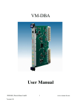
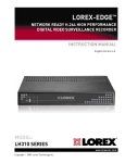
As described previously, our microterm project will use an LCD Controller (LCDC) as shown in
figure 1. The particular LCDC IC we are using is the RAiO RA8835 as implemented by Topway
on their TCB1335 controller board. The RA8835 is the modern version of the 1330/1335 series
of LCDC ICs made by Epson/Seiko, S-MOS, etc. that were popular in the 1990s.
Fig. 1: Topway TCB1335 LCD Controller Board
The RA8835 is a programmable controller IC with the following features:
• can accommodate monochrome LCD panels with resolutions up to 640x256 pixels
• supports text, graphics, and combined modes
• built-in character generator ROM and support for user-defined character generation (both
RAM- and ROM-based)
• programmable cursor control
• industry-standard 8-bit microprocessor interfaces (Intel 8080 and Motorola 6800 modes)
• 60-pin quad flat package (QFP)
• 2.7V to 5.5V operating supply
Features of the Topway TCB1335 controller board include:
• on-board LCDC IC oscillator (X1)
• on-board 32 KB SRAM display memory (U1)
• 5.0±0.5V operation, 13mA typ.
• on-board DC-DC converter to generate VEE (-20V) required for LCD panel
• 20-pin MCU interface (K2)
• 16-pin LCD panel interface (K3)
We will also be using the LM2028 LCD panel as the display with the following features:
• 320hx240v pixels
• 3~5.5V operation, 3.5mA typ.
• direct interface to K3 on TCB1335
• LED backlight built-in (3.5V @ 300mA)
2
CET360 Microprocessor Engineering
LCDC Guide v.2.6
2. Technical References
There are two primary references you will need when working with the LCDC – one for the
TCB1335 controller board1 (for hardware interfacing) and one for the RA8835 controller IC2 (for
software programming). Check the resources page on the course website for links to these two
documents. You may also need to refer to the datasheet for the particular LCD panel you will be
using.
3. Hardware / Interfacing
The TCB1335 is interfaced to a control processor (our ‘S12) via 20-pin connector K2 using an 8bit data bus and a single address line (A0). Control lines include an active-low chip select ( CS )
and either active-low read ( RD ) and write ( WR ) lines in 8080 mode or R/ W and Enable (E)
lines in 6800 mode. The reset ( RES ) line needs to connect to the system reset line. The choice
of interface mode is made via the interface select pin (SEL1) also on K2. Because the bus
interface mode would not need to be changed once selected, this pin should be permanently
tied to either VDD or VSS for a fixed logic high or low respectively. Refer to section 4.1 below
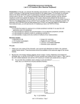
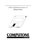
about how to best handle the SEL1 pin. In addition to supplying the board with usual power
connections (VDD and VSS), you will also need an external contrast control potentiometer on your
breadboard as shown in figure 2. This potentiometer allows you to adjust the contrast of the
LCD panel by varying the bias voltage (VO) between VDD and VEE. Finally, the TCB1335 also
supports backlight power connections for backlit panels by passing through the BLA (anode)
and BLK (kathode) pins from K2 to K3 (LCD panel connection). For the LM2028 panel operating
on 5VDC, a 18~33Ω resistor should be used between 5V and BLA. BLK must connect to
ground.
VDD
VO
10~20kΩ
VEE
Fig. 2: LCD Contrast Control
Recall that the particular S12C32 MCU we are using on the Dragonfly does not implement an
external data/address bus architecture; thus you may think that it is not possible to interface a
peripheral type device such as this LCDC IC to an MCU that is missing conventional bus pins.
Indeed, our S12C32 MCU can be described as being peripheral bus challenged. But wait: this is
Microprocessor Engineering – all things are possible! You will need to work with your team to
devise a scheme wherein you can “emulate” traditional bus operation using the I/O pins
available on our C32. Hint: use port T as a bidirectional “data bus” and some port M pins for
“control bus” signals as mentioned above plus the A0 address line.
CAUTION! Use extreme care when wiring the 20-pin DIP ribbon connector to the TCB1335 –
this connector does not use standard pin layout numbering!
4. Software / Programming
From a software implementation point-of-view, the LCDC/LCD combination should be viewed as
an output peripheral (albeit a sophisticated one). In a fashion similar to the SCI module
3
CET360 Microprocessor Engineering
LCDC Guide v.2.6
previously encountered, you should think in terms of a software “module” consisting of the
prescribed “.c” driver file (the implementation) and a “.h” header file (the client interface). From a
client’s (i.e. the main program) perspective, the following actions would be desirable:
•
•
•
•
•
•
•
initialize the LCDC
clear the LCD screen and move the cursor to the upper left corner
position the cursor to a particular line and column
output a single character at the current cursor position
output a character string at the current cursor position
scroll the screen contents up one line (“pan down”)
scroll the screen contents down one line (“pan up”)
Also, the client may want to know the screen geometry in terms of the number of lines and
characters per line displayable on the actual LCD. The screen geometry can vary from one LCD
model to another and may also depend on the character matrix geometry. For example, the
LM2028 QVGA LCD panels display a fixed 320h x 240v pixels. Given a 6x10 pixel character
matrix layout, this panel would then display 24 character lines of 53 characters per line. The
lines would be numbered 0..23 and the character columns would be numbered 0..52. The 5x7
character bitmaps provided by the character generator ROM built into the LCDC would fit nicely
into a 6x10 character matrix with 1 blank pixel column between characters horizontally and 3
blank pixel lines between character lines.
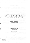
Did you notice the top-down approach being taken here? It all starts with “what would the client
of your LCD module need to know and do?”. Based upon the above description, we have our
basic header file designed as shown in figure 3! Obviously, this header file would be #included
by any client wishing to interact with the LCD (i.e. main.c).
/*
* LCD.h: interface for LCD driver
*/
#define LCD_LINES 24
#define LCD_COLS 53
void
void
void
void
void
void
void
// number of character lines
// number of columns per line
LCD_init(void);
// initialize LCD controller
LCD_clear(void);
// blank out entire LCD
LCD_goto(int line, int col); // move cursor to given line/col
LCD_putc(char);
// output a single char to LCD
LCD_puts(char *);
// send char string to LCD
LCD_scrollUp(void);
// scroll screen contents up
LCD_scrollDn(void);
// scroll screen contents down
Fig. 3: Basic LCD Driver Header File
Moving on to the actual driver itself (LCD.c), this is where we find all the detailed programmatic
coding to implement the above functions as well as any additional “support” routines internal to
the LCD driver. The support routines would typically be the very low-level functions that interact
with the LCDC itself. Of course, these would be considered private to the LCD implementation
and not be made available to the client via the header file. In order to design and implement the
software driver for the LCD, you will need to frequently refer to the LCD controller IC data sheet.
This reference should be thoroughly reviewed prior to continuing with these notes, which are
based on this assumption. Required technical knowledge of the LCDC is highlighted in the
following sections.
4
CET360 Microprocessor Engineering
LCDC Guide v.2.6
4.1 MCU Interface Select and Operation
From section 5 of the RA8835 data sheet, “Pin Descriptions”, you will note that the SEL1 pin
selects between Intel/8080 and Motorola/6800 modes. Although either mode works equally well,
the 8080 mode with separate RD and WR lines features slightly simpler strobe timing and is
therefore recommended. For MCU writes, the A0 address line selects between a “data” register
(when low) and a “command” register (when high). Figure 7-2A in the RA8835 data sheet shows
a typical 8080-mode interface and timing details are given in figure 10-3-1 of the data sheet.
This information is extremely important to both the hardware and software specialists and
should be thoroughly reviewed. As mentioned previously, we will be “emulating” bus-style
command and data transfers with the LCDC with our “busless” S12 MCU module. Looking at
the data sheet timing diagram of figure 10-3-1, we see the “recipe” for a MCU write operation:
1.
2.
3.
4.
5.
set the A0 line high (for command register) or low (for data register)
drive CS active-low
output a byte to the data “bus” and make sure the I/O port is an output
pulse the WRite line active-low then back to high
return the CS back to high
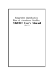
Given appropriate definitions for LCDBUS, LCDDDR, A0, CS, WR, HIGH, and LOW, we can
implement a “wrLCD” routine as given in figure 4 that will output a specified data byte to the
appropriate register in the LCDC. Observation: Did you notice how we jumped from a top-down
to a bottom-up approach here? Sometimes in embedded systems development, it may make
sense to apply step-wise development bouncing between top-down and bottom-up processes to
effectively meet in the middle.
/*
* wrLCD: lowest-level routine to write given data byte to LCDC
*
in: reg = address to write (1=command, 0=data),
*
data = data byte to write
*
out: none
*/
void wrLCD(int reg, Byte data)
{
A0 = reg;
// drive A0 line as given
CS = LOW;
// assert Chip Select
LCDBUS = data;
// send datum to LCDC
LCDDDR = 0xFF;
// make sure I/O port is all outputs
WR = LOW;
// stobe command byte to LCDC
WR = HIGH;
CS = HIGH;
// deassert Chip Select
}
Fig. 4: Low-level “wrLCD” Routine
It is also possible to perform read operations from the LCDC. This would occur if you wanted to
obtain either the LCDC’s current cursor position or display memory contents. In such cases, a
low-level “rdLCD” routine as given in figure 5 would be required.
5
CET360 Microprocessor Engineering
LCDC Guide v.2.6
/*
* rdLCD: lowest-level routine to read & return a data byte from LCDC
*
in: address to read (1=command, 0=data)
*
out: byte value read
*/
Byte rdLCD(int reg)
{
Byte result;
LCDDDR = 0;
// set I/O port to all inputs
A0 = reg;
// drive A0 line as given
CS = LOW;
// assert Chip Select
RD = LOW;
// assert RD strobe (8080 mode)
asm nop;
// read setup delay
result = LCDBUS;
// read datum from LCDC
RD = HIGH;
// deassert RD strobe
CS = HIGH;
// deassert Chip Select
return result;
// return datum read as result
}
Fig. 5: Low-level “rdLCD” Routine
4.2 LCDC Instruction Set
Because the LCDC is a fairly complex logic device, it implements a number of instructions that
may be followed by a variable number of data bytes according to the function of the instruction.
Section 6 of the RA8835 data sheet, “Instruction Set”, includes the instruction set summary
table followed by detailed descriptions of each instruction. Data sheet section 8-1-2 gives an
initialization example which serves as the recipe for setting up the LCDC, for which
LCD_init() has been identified to accomplish. You will need to study these sections
thoroughly to understand how these instructions are used. We will explore LCD_init() in
more detail in a later section.
For ease of programming within your LCD module (and to eliminate magic numbers!), a block of
#defines should be placed near the top of your LCD.c to define appropriate symbolic names for
the various LCDC commands. Note that these defines belong in LCD.c instead of LCD.h
because they are used exclusively in the driver implementation and never directly by the client!
These names also serve to provide a degree of documentation and increase overall code
quality. Figure 6 should give you the idea.
/*
* LCD Instruction Set (from RA8835 data sheet)
*/
#define CMD_SYSTEMSET 0x40
// Initialize device and display
#define CMD_SLEEPIN
0x53
// Enter standby mode
#define CMD_DISPLAYOFF 0x58
// Turn display off
#define CMD_DISPLAYON 0x59
// Turn display on
M // etc. (13 more lines)
Fig. 6: LCDC Instruction Set Symbolic Definitions
As a quick introduction, the commands in the system control and display control classes are
typically used only once during initialization while those in the drawing control and memory
control classes are used for general display content updates.
6
CET360 Microprocessor Engineering
LCDC Guide v.2.6
4.3 Memory Mapping and Cursor Addressing
As documented in the data sheet, the LCDC also provides a 16-bit address / 8-bit data interface
to its own display memory and the TCB1335 board includes 32KB of high-speed static RAM at
0x0000-0x7FFF for this display memory. The idea here is that your driver has to store ASCII
codes in the display memory which results in the respective character appearing on the LCD
screen. There are essentially two tricks to making this work correctly:
1) The display RAM is on the “other side” of the LCDC; thus the “MWRITE” LCDC
instruction must be used to get the ASCII codes transferred through the LCDC and into
the display RAM, and
2) The actual screen contents are mapped to a range of addresses in the display RAM;
thus ASCII codes must be written to specific display RAM locations to have them appear
at particular locations on the screen. See section 7-10 of the RA8835 data sheet for
further details.
The second requirement is exactly the reason for the “CSRW” (Cursor Write) instruction – so
that you can move the LCDC’s cursor around the display RAM thus causing subsequently
written characters to appear at controlled locations on the screen. The LCDC is also capable of
generating pixel-based graphics; however, this feature is not covered in this document. For
simplification, we will initialize the LCDC for no graphics page and a single character display
page starting at display memory location zero. A 24 line x 53 column text display would
therefore require a total of 1,272 bytes of display RAM for a full screen display. Note that this
small amount of display RAM (approx. 1.25KB) is typical of textual displays. However, a single
640x240 monochrome graphics page would require 20KB of the display RAM.
Challenge question: how much RAM would be required for a 1024x1024 color graphics display
using 24-bits per pixel?
4.4 LCDC Initialization
In order to initialize the LCDC and therefore the LCD screen display, you will need to determine
the appropriate data byte values for all the commands from “SYSTEM SET” through “OVLAY”
and arrange for LCD_init() to produce a series of write operations to accomplish the
initialization. Although you could use the wrLCD() low-level routine in figure 4 to send out each
command and data byte individually (30+ writes), this would be extremely tedious, error-prone,
and difficult to maintain. A much better method to accomplish this would be to combine a set of
initialization parameter arrays with a new “wrCommand” routine built on top of wrLCD() to offload the grunt work from LCD_init(). For example, the following line of code would
encapsulate the 8 data bytes required for the “SYSTEM SET” command into a data array. Note
that these values are specifically chosen for the LM2028 LCD geometry, a different LCD
geometry would require different values.
const Byte ParmsSysSet[] = {0x10, 0x05, 0x09, 52, 55, 239, 53, 0};
This definition, along with five others for those initialization commands requiring data
parameters, would be placed at the top of LCD.c after all #defines but before any routines. Once
the initialization data arrays are built, we next add wrCommand() as shown in figure 7. This nifty
utility routine accepts three arguments: a command, a pointer to a parameter data array (which
may be null), and the array length (which may be 0) and takes care of writing out a complete
command plus parameters to the LCDC using the lowest-level wrLCD() routine previously
described.
7
CET360 Microprocessor Engineering
LCDC Guide v.2.6
/*
* wrCommand: low-level routine to write command & data to LCDC
*
in: command = LCD command,
*
*parms = array of byte parameters,
*
length = length of parameter array (0 if none)
*
out: none
*/
void wrCommand(Byte command, const Byte *parms, Byte length)
{
int i;
wrLCD(1, command);
// output the LCDC command
for (i=0; i<length; i++)
// output all parameter bytes
wrLCD(0, parms[i]);
}
Fig. 7: “wrCommand” Routine
Now that we have a series of parameter data arrays and the wrCommand() routine, the
LCD_init() routine becomes drastically simpler as shown in figure 8.
/*
* LCD_init: initialize LCDC
*/
void LCD_init(void)
{
// initialize LCD output control lines
M
// initialize data direction registers
M
// LCDC initialization sequence according to data sheet fig. 8-1
wrCommand(CMD_SYSTEMSET, ParmsSysSet, sizeof(ParmsSysSet));
wrCommand(CMD_SCROLL,
ParmsScroll, sizeof(ParmsScroll));
M
// 5 more calls to wrCommand() here
LCD_clear(); // erase all the garbage from power-up
}
Fig. 8: “LCD_init” Routine
4.5 Other LCD Driver Routines
The initialization process is probably the most difficult part of the LCD driver. A test run at this
point should produce a blank display with a blinking underline cursor in the top-left corner. Don’t
forget to adjust the contrast control if need be! Once you have that working, the remaining
routines should be a breeze. The following sections provide some hints on what the other LCD
driver routines should do.
4.5.1 LCD_clear()
- position the cursor to 0,0 [call LCD_goto(0,0)]
- use a for loop to output “LCD_LINES * LCD_COLS” ASCII blank spaces via
LCD_putc()
- reposition the cursor to 0,0
4.5.2 LCD_goto(int line, int col)
- compute a new display memory cursor address based on the given line & col
- use wrCommand() with CMD_CSRW to update the LCDC’s cursor address
8
CET360 Microprocessor Engineering
LCDC Guide v.2.6
Hint: be careful of the byte ordering here – since the S12 is “big endian”, you’ll need to
swap bytes before sending to the LCDC.
4.5.3 LCD_putc(char chr)
- If the given char is not a control character, use wrCommand() with CMD_MWRITE to
output the ASCII character and exit LCD_putc(). In order to send ‘chr’ to
wrCommand(), you’ll need to pass chr’s address using the ‘&’ C operator (you may also
need a typecast here).
- for the control characters listed in figure 9, handle appropriately
Ctrl Char
BS
HT
LF†
VT†
FF
CR
Function
move cursor left one column unless already in col 0
move cursor right to next “tab stop” (even multiple of 8 columns)
move cursor down 1 line, calling LCD_scrollUp() if needed
move cursor up 1 line, calling LCD_scrollDn() if needed
clear screen and home cursor; i.e. call LCD_clear()
move cursor to column 0 of current line
Fig. 9: Basic Control Character Functions
†: VT and LF should be able to scroll past the top and bottom lines respectively.
4.5.4 LCD_puts(char *str)
- Call LCD_putc() in a loop for each character in the given string, just like you did in
SCI_puts().
4.5.5 LCD_scrollUp()
- forward scroll display screen contents by 1 line
Hint: advance the LCDC’s startaddress (SAD1) of your text page by LCD_COLS bytes.
Don’t forget to also clear the newly exposed line at the bottom of the screen. See the
RA8835 data sheet, section 7-13 for additional details.
4.5.6 LCD_scrollDn()
- backward scroll display screen contents by 1 line
Hint: see the hint for LCD_scrollUp()!
4.6 Scrolling
What should happen when the LCD screen is filled, the cursor is at the bottom-right corner, and
one more character is sent to the LCD module? A first possibility would be to start over in the
top-left corner, effectively overwriting the current display. This is not considered “standard”
behavior. The second and generally accepted possibility is to shift the bottom n-1 lines to the
top n-1 lines and continue displaying additional characters on the new bottom line. However, as
you might guess, it would be an ugly and time-consuming process to move all these characters
and lines programmatically.
As described in section 7-13 of the RA8835 data sheet, “Scrolling”, and shown there in figure 724, we can employ the LCDC’s inter-page scrolling feature to support very high-speed,
9
CET360 Microprocessor Engineering
LCDC Guide v.2.6
hardware-assisted display scrolling. Although the displayed screen contents will initially be
generated from the first “page” of display memory, the 32KB of display RAM on the TCB1335
board can support a large number of display pages. The trick to getting display scrolling to work
is to manipulate the LCDC’s startaddress1 (SAD1) register via the SCROLL command. For the
LCD_scrollUp() function, you would add LCD_COLS to SAD1. This effectively moves line 2
to line 1, line 3 to 2, etc. and would open a new line at the bottom of the display; which you
should clear to all blanks. This addition process could continue as needed and the 16-bit
address counter registers within the LCDC would simply wrap-around at the end of the display
memory.
For reverse-scrolling, LCD_scrollDn() would subtract LCD_COLS from SAD1. No clearing of
the newly recalled line 1 would be needed resulting in the feature to scroll back in display
history.
When scrolling the display contents, there are two other small problems that must be properly
handled. The first problem is when doing cursor addressing in LCD_goto(), the changing
display start address must be added to the new cursor address to insure the new cursor
location appears in the proper location on the screen. The easiest way to solve this problem is
have a word variable local to LCD.c that keeps track of the current value of SAD1. Thus,
LCD_scrollUp() and LCD_scrollDn() should respectively add and subtract LCD_COLS to
this variable and rewrite this variable to SAD1 via the SCROLL command. Then in
LCD_goto(), you would also add this variable to the new cursor address betore sending this
value to the CSRW command.
The second problem is the position of cursor when performing scrolls. If the cursor position is
not adjusted during the scroll operation, it will move away from its current position (and possibly
even off-screen!) which is quite distracting to the user. Indeed, the cursor should also move
down or up by one line for each LCD_scrollUp() or LCD_scrollDn() call respectively. The
solution for this would be for both of these routines to first acquire the current cursor position
relative to the beginning of the display, then to update SAD1 as described in the previous
paragraph, and then finally to reposition the cursor to the previous relative position. To acquire
the current relative cursor position, these two routines could call a new low-level support
routine, getCrsAddr() shown in figure 10, to retrieve the LCDC’s cursor address register via
the CSRR command and then subtract the current display start address. This value would then
be used by LCD_scrollUp() and LCD_scrollDn() before exiting by calling LCD_goto().
/*
* getCrsAddr: get & return current cursor address
*
in: none
*
out: current cursor address as a 16-bit int
*/
Word getCrsAddr()
{
Byte parms[2];
wrCommand(CMD_CSRR, NULL, 0); // issue cursor read command
parms[0] = rdLCD(1);
parms[1] = rdLCD(1);
return (parms[1]*256 + parms[0]); // byte swapped
}
Fig. 10: Low-level “getCrsAddr” Routine
10
CET360 Microprocessor Engineering
LCDC Guide v.2.6
4.7 Convenience Macros
One of the neatest tricks of programming in C is the use of the preprocessor’s macro feature. In
the development of embedded system projects, the macros shown in figure 11 demonstrate
some commonly needed constants and functions. The MSB, LSB, and SWAP macros
manipulate a word argument while the PULSE macros may be used to create logic pulses on
output pins.
// some handy macros
#define LOW 0
#define HIGH 1
// extract most significant byte of a word
#define MSB(w) (w >> 8)
// extract least significant byte of a word
#define LSB(w) (w & 0xff)
// swap high/low bytes of a word
#define SWAP(w) (MSB(w) + (LSB(w)<<8))
#define PULSE_LO(pin) pin=0; pin=1
#define PULSE_HI(pin) pin=1; pin=0
// create active low pulse
// create active hi pulse
Fig. 11: Some Handy Macros
5. Q&A
[possible question / answer section here – what would you like to see here?]
6. References
1. TCB1335 LCD Module Controller Board User Manual, rev. 0.1, Topway Technology Co., Jun. 2004.
2. RA8835 Dot Matrix LCD Controller Specification, ver. 1.7, RAiO Technology Inc., Aug. 2006.
11