1
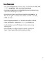
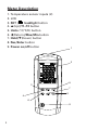
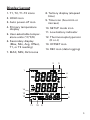
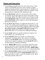
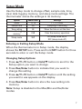
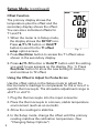
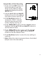
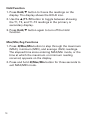
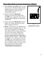
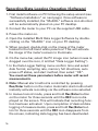
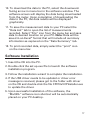
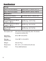
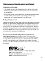
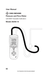
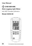
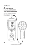
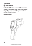
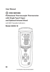
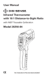
User Manual Thermocouple Thermometer with Dual Type K/J Inputs and Data Logging with NIST-Traceable Calibration Model 20250-02 THE STANDARD IN PRECISION MEASUREMENT Introduction The Digi-Sense Thermocouple Thermometer with Dual Inputs and Data Logging (Model 20250-02) offers fast response and high accuracy. This thermometer accepts two thermocouple sensors (type K or J). Advanced features include data logging, USB interface, relative time clock, offset compensation, temperature differential, data Hold, Max/Min/Avg readings, and auto power-off. The instrument is fully tested and calibrated to NIST-traceable standards. Careful use of this meter will provide years of reliable service. Unpacking Check individual parts against the list of items below. If anything is missing or damaged, please contact your instrument supplier immediately. will provide years of reliable service. 1. Meter 2. Two type K flexible probes 3. USB cable 4. Software 5. Three AAA batteries 6. User manual 7. NIST-traceable calibration report with data 2 Key Features • Large backlit display shows any combination of T1, T2, T1–T2; plus Max, Min, and Avg readings • Relative time clock on Max/Min/Avg provides a time reference for major events • Electronic Offset function allows compensation of thermocouple errors to maximize overall accuracy • USB interface • Data logging capacity of 18,000 sampling points • User-selectable readout in °C, °F, or Kelvin (K) • Automatic power-off (sleep) mode conserves battery life • Dual sensor inputs; accepts a wide variety of type K and type J thermocouple probes 3 Meter Description 1. Temperature sensor inputs (2) 2. LCD 3. SET / backlight button 4. (Up)/T1–T2 button 5. Units (°C/°F/K) button 6. (Return)/Max/Min button 7. Hold/(Down) button 8. Rec/Enter button 9. Power on/off button 1 2 5 3 7 8 4 6 9 4 Display Layout 8. Tertiary display (elapsed time) 1. T1, T2, T1–T2 icons 2. HOLD icon 3. Auto power-off icon 9. Time icon (hour:min or min:sec) 4. Primary temperature display 10. SETUP mode icon 11. Low-battery indicator 5. User-selectable temperature units (°C/°F/K) 12. Thermocouple type icon (K or J) 6. Secondary display (Max, Min, Avg, Offset, T1, or T2 reading) 13. OFFSET icon 14. REC icon (data logging) 7. MAX, MIN, AVG icons 2 3 1 4 5 6 14 7 13 12 8 11 10 9 5 Setup and Operation 1. Press Power on/off button to turn the unit on. The value immediately shown is the number of data logging sample points remaining (from 18,000 to 0). After one second, the display will then switch to the temperature measurement reading mode. 2. Press Rec/Enter button for three seconds to start recording and press again for three seconds to stop recording. When the thermometer is in Setup mode, press Rec/Enter button to enter a setup option and press Rec/Enter button again to store the displayed setting in memory. 3. Press /T1–T2 button to toggle showing the T1, T2, and T1–T2 (differential temperature) measurements in the primary and secondary displays. When the meter is in Setup mode, press /T1–T2 button to scroll to the Setup option you want to change or press /T1–T2 button to increase the displayed setting. 4. Press Units button to switch between Celsius (°C), Fahrenheit (°F), and Kelvin (K). 5. Press Hold/ button to freeze or unfreeze the displayed readings. When the meter is in Setup mode, press Hold/ button to scroll to the Setup option you want to change or press Hold/ button to decrease the displayed setting. 6. Press t/Max/Min button to step through the maximum, minimum, and average readings. To exit the Max/Min/Avg mode, press and hold the t/Max/Min button for three seconds to return to normal operation. 6 7. Press Set/backlight button to turn the backlight on and off. Press and hold the Set/backlight button for three seconds to enter or exit the Setup mode. (See "Changing Setup Options") Setup Mode Use the Setup mode to change offset, sample rate, time, clear data logging memory, and sleep mode settings. The thermometer stores the settings in its memory. Option Offset Sample rate Time setting Clear data logging memory Menu item T1, T2 rAt tiE Settings T1 , T2 offset Sampling of recording Show the time or set the time CLR Clear the memory operation Sleep mode SLP On (sleep mode on) or OFF (sleep mode off) Entering or Exiting Setup Mode When the thermometer is in Setup mode, the display shows the SETUP icon. Press and hold SET button for three seconds to enter or exit the Setup mode. Changing Setup Options 1. Press /T1–T2 button or Hold/ button to scroll to the Setup option you want to change. 2. Press Rec/Enter button to indicate that you want to change this setting. 3. Press /T1–T2 button or Hold/ button until the setting you want to use appears on the display. 4. Press Rec/Enter button to store the new setting into memory. Note: Setup is disabled in the Max/Min and Rec/Enter modes. 7 Setup Mode (continued) Offset Function The primary display shows the temperature plus the offset and the secondary display shows the offset. You can store individual offsets for T1 and T2. 1. When the meter is in Setup mode, the display shows the SETUP icon. Press /T1–T2 button or Hold/ button to scroll to the T1 offset Fig. 1 setup option screen. 2. Press Rec/Enter button to access the T1 offset value shown in the secondary display. 3. Press /T1–T2 button or Hold/ button until the setting you want to use appears on the display (Fig. 1). Press Rec/Enter button to store the new setting in memory and continue to T2 offset. Using the Offset to Adjust for Probe Errors Use the offset option in the Setup mode to adjust the thermometer’s readings to compensate for the errors of a specific thermocouple. The allowable adjustment range is ±9.0°F or ±5.0°C. 1. Plug the thermocouple into the input connector. 2. Place the thermocouple in a known, stable temperature environment (such as an ice bath). 3. Allow the readings to stabilize. 4. In the Setup mode, change the offset until the primary reading matches the calibration temperature. (See “Changing Setup Options") 8 Sample Rate of Data Recording 1. P ress and hold SET button for three seconds to enter the Setup mode. While in Setup mode, the display shows the SETUP icon. 2. U se the /T1–T2 and Hold/ buttons to scroll to the rate setting option screen (see Fig. 2). 3. Press Rec/Enter button to access the “00:01” (minute, second) value shown in the tertiary display (see Fig. 2). Fig.Fig. 2 2 4. Press t/Max/Min button until the minute value is flashing. Use the /T1–T2 and Hold/ buttons to set the desired value. 5. Press t/Max/Min button again until the second value is flashing. Use the /T1–T2 and Hold/ buttons to set the desired value. 6. Press Rec/Enter button to store the new setting in memory. 7. N ote: When the meter is powered down, the default sample rate is the last setting. 9 Setup Mode (continued) Time Setting Function 1. Press and hold SET button for three seconds to enter the Setup mode. While in Setup mode, the display shows the SETUP icon. 2. Use the /T1–T2 and Hold/ buttons to scroll to the time setting option screen (Fig. 3). 3. Press Rec/Enter button to access the values (Fig. 4). The primary display shows the year, the secondary display shows the month and day, the tertiary display shows the hour and minute. Fig. 3 Fig. 3 4. Press t/Max/Min button until the year value is flashing. Use the /T1–T2 and Hold/ buttons to set the desired value. 5. Press t/Max/Min button again until the month value is flashing. Use the /T1–T2 and Hold/ buttons to set the desired value. Fig. 4 Fig. 4 6. Press t/Max/Min button again until the day value is flashing. Use the /T1–T2 and Hold/ buttons to set the desired value. 10 7. Press t/Max/Min button again until the hour value is flashing. Use the /T1–T2 and Hold/ buttons to set the desired value. 8. Press t/Max/Min button again until the minute value is flashing. Use the /T1–T2 and Hold/ buttons to set the desired value. 9. Press Rec/Enter button to store the new setting in memory. Clear Memory Operation Immediately after turning on the meter, the first value shown is the number of data logging sample points remaining (from 18,000 to 0). Once the memory is full, the first value shown will be “FULL” rather than a number. Or if you try to record, the REC icon will flash five times and disappear. At this point, you are no longer able to record until the memory is cleared. 1. Press and hold SET button for three seconds to enter the Setup mode. While in Setup mode, the display shows the SETUP icon. 2. Use the /T1–T2 and Hold/ buttons to scroll to the CLR memory option screen (Fig. 5). The screen indicates the number of sample points remaining. 3. Press Rec/Enter button and “No” appears on the screen. (Fig. 5) Fig. 5 Fig. 5 Screen shows 17,985 readings left in memory. 11 Setup Mode (continued) 4. Press /T1–T2 button or Hold/ button until the display shows “YES”, indicating the memory will be cleared. 5. Press Rec/Enter button to select the “YES” setting and clear the memory. Data logging capacity now returns to 18,000 sample points. Auto Power-Off (APO)/Sleep Mode The meter’s default mode is to automatically shut off after 15 minutes of non-use. To disable the auto power-off mode, enter the Setup mode. 1. While in Setup mode, press /T1–T2 or Hold/ button to scroll to the “SLP” option screen (Fig. 6). 2. Press Rec/Enter button to display “On.” 3. Use the /T1–T2 and Hold/ buttons to toggle between “On” (sleep mode on) or “Off” (sleep mode off). 4. Note: Meter defaults back to “On” once meter is powered off. 12 Fig. 6 Measuring Temperatures 1. Plug the thermocouple(s) into the T1 or T2 input connector(s). Make sure that the polarity is correct. 2. Press Power on/off button to turn the unit on. The value immediately shown is the number of data logging sample points remaining (from 18,000 to 0). After one second, the display will then switch to the first temperature measurement reading. Note: If no thermocouple is plugged into the selected input or the thermocouple is not connected properly, the display shows "- - - - ". If the temperature being measured is outside the thermocouple’s valid range, the display shows “OL” (overload). 3. Set the thermometer for the correct thermocouple type (K or J) in the Setup menu. 4. Press the Unit button to select the desired temperature scale (°C, °F, or K). 5. Hold or attach the thermocouple(s) to the measurement location. The temperature reading appears in the primary display. Use the /T1–T2 button to toggle between showing the T1, T2, and T1–T2 readings in the primary or secondary display. 13 Hold Function 1. Press Hold/ button to freeze the readings on the display. The display shows the HOLD icon. 2. Use the /T1–T2 button to toggle between showing the T1, T2, and T1–T2 readings in the primary or secondary display. 3. Press Hold/ button again to turn off the Hold function. Max/Min/Avg Functions 1. Press t/Max/Min button to step through the maximum (MAX), minimum (MIN), and average (AVG) readings. The elapsed time since entering MAX/Min mode, or the time at which the maximum or minimum reading occurred, appears on the display. 2. Press and hold t/Max/Min button for three seconds to exit MAX/MIN mode. 14 Recording/Data Logging Operation (Meter) 1. Press Power on/off button to turn the unit on. The first value immediately shown is the number of data logging sample points remaining. (Fig. 7) 2. Press and hold Rec/Enter button for three seconds until the REC icon appears. The meter is now data logging temperature readings. 3. Press and hold Rec/Enter button again for three seconds to stop data logging function. 4. Note: A maximum of 18,000 sample points is available (Fig. 7). As you log temperature readings, this value will be lower each time you turn the meter. When the memory is full (with 0 sample points remaining), the first value shown will be “FULL” rather than a number. Or if you try to record, the REC icon will flash five times and disappear. At this point, you are no longer able to record until the memory is cleared. (See "Changing Setup Options", "Clear Memory Operation") Fig. 7 Fig.7 18,000 Screen shows readings left in memory. 15 Recording/Data Logging Operation (Software) 1. First install software on PC following the setup wizard (see “Software Installation” on next page). Once software is successfully installed, the “MultiDL” software icon shortcut will be automatically placed on your PC desktop. 2. Connect the meter to your PC via the supplied USB cable. 3. Power the meter on. 4. Open the installed Multi Data Logger Software by doubleclicking on the “MultiDL” icon on your PC desktop. 5. When opened, double-click on the image of the meter located in the left-hand white pane box. This will activate the image of the meter’s screen to illuminate. 6. On the menu bar, select the PC image icon (when mouse is dragged over the icon, it is titled “Data Logger Setting”). 7. In the Data Logger Setting menu confirm time and select date format, sampling rate, memory full directions, auto power-off status, and start method, then select “OK”. You must set these parameters before meter will record measurements. 8. Note: Manual start method is controlled by pressing Rec/Enter button on the meter. Automatic start method will instantly activate recording via the software once selected. 9. In manual record mode, press and hold Rec/Enter button on the meter for three seconds until the REC icon is displayed on the screen. This will indicate that recording function has been activated. Upon completion of desired data logging of measurements, press and hold Rec/Enter button for three seconds until the REC icon disappears from the screen, indicating data logging has been deactivated. 16 10. To download the data to the PC, select the downwardfacing arrow in menu bar in the software window. The software screen will display the data being downloaded from the meter. Upon completion of downloading the data to the PC, the data results will be displayed graphically. 11. T o save the measurement data to your PC select the “Data List” tab to open the list of measurements recorded. Select “File” icon from the menu bar and save data to desired location on your PC. Note: Data will be saved in an Excel® format that will include all summary information as captured on the “Data Summary” tab. 12. To print recorded data, simply select the “print” icon on the menu bar. Software Installation 1. Insert the CD into the PC. 2. Double-click the set up.exe file to launch the software installation program. 3. Follow the installation wizard to complete the installation. 4. If the USB driver needs to be updated or driver error message is received, please got to the folder with driver on the CD and double-click the file CP210xVCPInstaller.exe to update the driver. 5. Upon successful installation of the software, the “MultiDL” software icon shortcut will be automatically placed on your PC desktop. 17 Specifications Range Type K thermocouple(s) –328 to 2501°F (–200 to 1372°C) Type J thermocouple(s) –346 to 2012°F (–210 to 1100°C) Resolution Temperature display 0.1 below 1000 or 1 above 1000 Accuracy 18 T1, T2 temperatures above –148°F (–100°C) ±[0.5% rdg + 1.8°F (1°C)] T1, T2 temperatures below –148°F (–100°C) ±[0.5% rdg + 3.6°F (2°C)] T1–T2 temperature differential ±[0.5% rdg + 3.6°F (2°C)] Auto power-off Unit shuts off automatically after 15 minutes to preserve battery life Operating temperature 32 to 122°F (0 to 50°C) Storage temperature 14 to 122°F (–10 to 50°C) Weight 6.2 oz (177 g) Dimensions 63⁄8 " x 21⁄2 " x 11⁄8 " (16.2 x 6.4 x 2.9 cm) Power Three AAA batteries Maintenance, Recalibration, and Repair Cleaning and Storage • The meter should be cleaned with a damp cloth and mild detergent when necessary. Do not use solvents or abrasives. • Store the meter in an area with moderate temperature and humidity (refer to the operating and storage ranges in the "Specifications" on page 18). Battery Replacement When the battery power falls low, the low-battery icon will appear on the screen. Replace the three AAA batteries by removing the screw holding the rear battery compartment cover to access the battery compartment. Ensure that the compartment cover is securely fastened when finished. Note: If you do not intend to use the meter for a long time, remove the batteries. It is recommended that Digi-Sense products are calibrated annually to ensure proper function and accurate measurements; however, your quality system or regulatory body may require more frequent calibrations. To schedule your recalibration, please contact InnoCal, an ISO 17025 calibration laboratory accredited by A2LA. Phone: 1-866-INNOCAL (1-866-466-6225) Fax: 1-847-327-2993 E-mail: [email protected] Web: InnoCalSolutions.com 19 For Product and Ordering Information, Contact: Toll-Free: 1-800-323-4340 Phone: 1-847-549-7600 Fax: 1-847-247-2929 ColeParmer.com/Digi-Sense 1065DGMAN_20250-02 Rev.1 Toll-Free: 1-800-358-5525 Phone: 1-847-327-2000 Fax: 1-847-327-2700 Davis.com/Digi-Sense Manual Part No. 00100-34