1
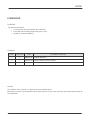
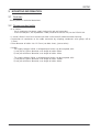
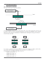
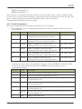
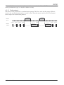
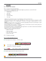
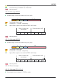
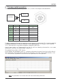
MANUEL D'INTERFACE
ERCP81
USER MANUAL
Document reference: ERCP81-UM-1.1-EN
BALOGH SA
BALOGH TAG
189 Rue d’Aubervilliers - CP 97 - 75886 Paris
Cedex 18 - France
Téléphone: 33 (0)1 44 65 65 00
Fax: 33 (0)1 44 65 65 10
Web: http://www.balogh-rfid.com
3637 Old US-23
Brighton, Michigan MI 48114, USA
Tel: USA (800) 252-RFID (7343)
(810) 360-0182
Canada (800) 258-RFID (7343)
Fax: (810) 360-0237
ERCP81
FOREWORD
PURPOSE
This document contains:
• a review of the general operation of an ERCP81
• instructions for installing and operating the system
• guidelines for troubleshooting
UPDATES
Version
Page index
Date
Description of changes
1
0
2006-03-02 Original document
1
1
2012-05-29 Update: improvement of drafting.
NOTES
The contents of this manual are subject to changes without notice.
BALOGH can not be held responsible for the consequences of any error, omission, or incorrect interpretation of
the information.
ERCP81-UM-1.1-EN
2/24
ERCP81
TABLE OF CONTENTS
OBJECTIVE OF THE DOCUMENT......................................................................................................................... 4
3.1.
PURPOSE ............................................................................................................................................................. 4
2
PACKAGE CONTENTS ............................................................................................................................................ 5
3
MOUNTING INFORMATION .................................................................................................................................... 6
3.1
FEATURES ............................................................................................................................................................ 6
3.2
RECOMMENDED CABLE ........................................................................................................................................ 6
4
PRODUCT DESCRIPTION ....................................................................................................................................... 7
4.1
OVERVIEW ........................................................................................................................................................... 7
4.1.1
ERCP81........................................................................................................................................................... 7
4.1.2
Interchangeability/mixability with other Balogh products.............................................................................. 7
4.2
FUNCTIONAL DESCRIPTION .................................................................................................................................. 8
4.2.1
Behaviour in operation ................................................................................................................................... 8
4.2.2
Serial link protocol: ........................................................................................................................................ 9
1
4.2.2.1
Radio protocol: ........................................................................................................................................................... 11
4.2.3
Sequence diagrams ....................................................................................................................................... 12
4.3
INTERFACES ....................................................................................................................................................... 14
4.3.1
Serial Link Interface...................................................................................................................................... 14
4.3.1.1
4.3.1.2
Transmission characteristics ....................................................................................................................................... 14
Master messages ......................................................................................................................................................... 14
4.3.1.2.1
Message MA14 (ID = 5) ................................................................................................................... 14
4.3.1.3
Slave messages ........................................................................................................................................................... 15
4.3.1.3.1
Message ES14 (ID = 3).................................................................................................................... 15
4.3.1.4
4.3.1.5
ACK, NAK, ERR messages ....................................................................................................................................... 16
Service Commands ..................................................................................................................................................... 16
4.3.1.5.1
Read firmware ................................................................................................................................... 16
4.3.1.5.2
Read status ........................................................................................................................................ 17
4.3.1.5.3
Reset .................................................................................................................................................... 17
4.3.1.5.4
Set ACK temporization ........................................................................................................................ 18
4.3.1.5.5
Read ACK temporization ..................................................................................................................... 18
4.3.1.5.6
Read EEPROM contents ...................................................................................................................... 18
5
FIRMWARE UPDATE PROCEDURE .................................................................................................................. 20
6
MAINTENANCE ...................................................................................................................................................... 22
ANNEXE A:
CABLE ASSEMBLY FOR SHIELDED CONNECTORS ................................................................. 23
ERCP81-UM-1.1-EN
3/24
ERCP81
1 OBJECTIVE OF THE DOCUMENT
3.1. Purpose
This document provides useful information for the user that will integrate ERCP81 in a system. This
User Manual deals with the following items:
• Package contents.
• Mounting information.
• Description of the ERCP81 product. This section provides a product overview, a quick
description of the ERCP81 functions and how to interface the ERCP81 via a serial link
• Firmware upgrade procedure.
• Maintenance and troubleshooting help.
• Annexes
ERCP81-UM-1.1-EN
4/24
ERCP81
2 PACKAGE CONTENTS
The ERCP81 inductively coupled transponder is shipped in a labelled cardboard box.
When unpacking, please ensure that the following items are present:
• 1x
ERCP81 (with protection cap on connector),
• 1x
Technical data-sheet.
ERCP81-UM-1.1-EN
5/24
ERCP81
3 MOUNTING INFORMATION
3.1 Features
See the product’s technical datasheet.
3.2 Recommended cable
• 6 or 8 wires:
- 2 or 4 conductors for power supply (refer to the pin out hereunder).
- 2 twin twisted pairs; line impedance: 120 (matched inside the unit) for the RS-422 link.
• 1 overall shield; it must be in contact over 360° to the metallic cable connector housing.
• Connection of conductors to the cable connector by crimping; conductor. wire gauge: 0,5 to
1,5mm².
• Outer diameter of cable: 8 to 1 2.5 mm (see data sheet, § accessories).
• Length:
- For supply voltage: 24Vdc, a voltage drop of 3volts can be accepted, with:
1) one pair of 1.5mm² diameter, max length of cable: 540m.
2) one pair of 0.5mm² diameter, max length of cable: 180m.
- For supply voltage: 29Vdc, a voltage drop of 8volts can be accepted, with:
1) one pair of 1.5mm² diameter, max length of cable: 1200m.
2) one pair of 0.5mm² diameter, max length of cable: 480m.
ERCP81-UM-1.1-EN
6/24
ERCP81
4 Product description
4.1 Overview
4.1.1 ERCP81
ERCP81 was developed for railway applications. This product is always operated in pairs, one on the
ground and one on-board a vehicle. Once they are close enough, the two enter into radio
communication exchanging messages through inductive coupling. The ERCP81 which is opposite is
hereafter in this document referred to as the counterpart.
ERCP81 is a short range transmitter/receiver that dialog at 13.56 MHz. This integrated device
includes an antenna and provides a cylindrical connector. The communication range is below than 1
meter.
Each ERCP81 is connected to a host or external controller, for example a programmable PLC or a
computer, through a RS 422 serial link. The ERCP81 sends by radio the data received by the host. On
the other hand, the data received by radio from the counterpart is transmitted periodically to the host.
The behavior is symmetrical for both counterparts. The radio dialog is done in half-duplex secured by
a 16-bit CRC and lasts while the counterparts remain in presence.
Both devices (the fix one and the mobile one) are identical. However, one must be declared as
“Master” and the other one as “Slave” so that they don’t dialog in the same time. So, the master sends
periodically a “Request to Send” frame. If a Slave receives it, it sends a data frame. Then the Master
sends its data.
The role of the ERCP as Master or Slave is defined by the function ID of the message sent by the host.
For example:
• If the host sends a message with a function ID = 3 on the serial link, the ERCP81 will be set
into Slave mode.
• If the host sends a message with a function ID = 5 on the serial link, the ERCP81 will be set
into Master mode.
4.1.2 Interchangeability/mixability with other Balogh products
ERCP81 can be mixed with and/or replaced by BALOGH ERES 1307 and 1308. ERES 1307 and
1308 are transmitters/receivers developed on the base of ERCP81, on which additional features have
been integrated, like:
• 5 inputs. On discrete input is reserved to trigger into ERCP81 mode.
• 5 outputs. One discrete output is reserved to indicate counterpart presence.
• Inputs/outputs are available on an additional cylindrical connector.
• Preset radio frames. Up to 4 frames are stored in Non Volatile Memory, selectable through
inputs.
• Periodic send of Life message on Serial link.
• Configurable temporizations saved in Non Volatile memory.
ERES 1307 and ERES 1308 are same products, excepted that they were developed on different
hardware. They are used in safety systems, in which redundancy is required and the devices shall have
different implementations to avoid common mode failures.
See documentations ERES 1307 and ERES 1308.
ERCP81-UM-1.1-EN
7/24
ERCP81
4.2 Functional description
4.2.1 Behaviour in operation
The figure below depicts a typical installation.
PLC/computer
RS 422
Board
ERCP81
ERCP81
Ground
RS 422
PLC/computer
A couple of ERCP81 connected each to a host behave like a cross cable. It means that a message sent
by a host to another one will be transmitted through the serial link and the ERCP81 couple, provided
that they are close enough to communicate. Communication is full duplex: messages are sent and
received in the same time.
host
Message X
host
Message Y
ERCP81
ERCP81
ERCP81
ERCP81
Message X
host
Message Y
host
So as to have a communication between ERCP81, one has to be configured as Master, and the other
one as Slave. The host sends a command on the serial link to set the ERCP mode.
Commands that set the ERCP81 into Master mode are:
- MAID14 (function ID = 5),
- MAID6 (function ID = 6),
- MAID7 (function ID = 7),
- MAID9 (function ID = 9).
ERCP81-UM-1.1-EN
8/24
ERCP81
Commands that set the ERCP81 into Slave mode are:
- ESID14 (function ID = 3),
- ESID8 (function ID = 8).
These messages also transport data and some have an error counter. Once a valid serial link message
is received, it is stored in an internal buffer, ready to be sent to the counterpart by radio. The only data
that can change during the transmission from PLC to PLC is the error counter.
Communication principles are given hereafter:
4.2.2 Serial link protocol:
Messages exchanged on the serial link can be divided in to 3 categories:
• Data commands: they are synchronous commands sent to the counterpart. The list is given in
the table below:
Function
Name
Description
Expected response
3
ESID14
Slave assignment. Send data to the
counterpart. Data size is fixed to 14 bytes.
ACK, NAK, (none)
5
MAID14
Master assignment. Send data to the
counterpart. Data size is fixed to 14 bytes.
ACK, NAK, (none)
6
MAID6
Master assignment. Send data to the
counterpart. Data size is in the range [0, 32].
ACK, NAK, (none)
7
MAID7
Master assignment. Send data to the
counterpart. Data size is in the range [0, 32].
ACK, NAK, (none)
8
ESID8
Slave assignment. Send data to the
counterpart. Data size is in the range [0, 32].
ACK, NAK, (none)
9
MAID9
Slave assignment. Send data to the
counterpart. Data size is in the range [0, 32].
ACK, NAK, (none)
• Automatic messages: they are asynchronous messages sent by the ERCP81 to the host. They
are message received from the counterpart, or ERR messages that indicate a radio
communication failure.
Function
Name
Description
3
ESID14
Data received from the counterpart(14 bytes).
5
MAID14
Data received from the counterpart(14 bytes).
6
MAID6
Data and radio error counter received from the counterpart. Data size
is in the range [0, 32].
7
MAID7
Data and radio error counter received from the counterpart. Data size
is in the range [0, 32].
8
ESID8
Data and radio error counter received from the counterpart. Data size
is in the range [0, 32].
9
MAID9
Data and radio error counter received from the counterpart. Data size
is in the range [0, 32].
4
ERR
Radio transmission error.
ERCP81-UM-1.1-EN
9/24
ERCP81
• Service commands. They are synchronous commands used to control or to get the ERCP81
status.
Function
Description
Expected response
0Ah
Read firmware version
Firmware version
12h
Read status
ERCP81 status
19h
Reset ERCP81
ACK, NAK, (none)
21h
Set ACK temporization
ACK, NAK, (none)
23h
Read ACK temporization
Temporization
10h
Read EEPROM contents
EEPROM data
Data messages from the host are acknowledged (ACK message) by the ERCP81, except during radio
dialog. If the message received on the serial link is not valid (parity error, unexpected length ...), the
ERCP81 returns a NAK message. The delay between last radio dialog and next acknowledged
message (called tempo_ACK) is configurable and saved in Non Volatile Memory. The following
scheme depicts messages exchanges between a host and an ERCP81.
send data
Radio dialog
No radio dialog
Message X
Host1
Radio dialog
Message X
Message X
Message X
dialog end
Message X
Message X
Message X
Message X
ERCP1
(Serial)
ACK
ERCP 1
Host1
(Serial)
ACK
ACK
Message Y
Message Y
Message Y Message Y
Tempo_ACK
Last data message to the host is repeated once after the counterpart has disappeared.
The diagram below gives the duration between messages sent on the serial link.
send data
Radio dialog
Radio dialog failed
ERR
ERR
Radio dialog OK
data
data
data
dialog end
data
data
Last data
message
Serial link
500 ms
80 ms
ERR messages are sent every 500 ms.
Data messages (MAIDx, ESIDx) period is about 80 ms.
ERCP81-UM-1.1-EN
10/24
ERCP81
When radio failures occur, an internal counter is incremented and ceiled to 15. This counter is used in
some operation messages (see details in further section).
4.2.2.1 Radio protocol:
The master sends periodically a synchronisation pattern. The Slave waits for this pattern. When it
receives the synchronisation pattern, it sends its data. Then the master sends its data. The diagram
below depicts the transmission protocol.
send data
send data
ERCP81
(Slave)
Synchro Synchro Synchro Synchro
Send data
Synchro
Send data
Synchro Synchro
ERCP81
(Master)
ERCP81-UM-1.1-EN
11/24
ERCP81
4.2.3 Sequence diagrams
Following diagrams aim at understanding interactions between serial link messages and radio
messages.
The sequence diagram below depicts a typical operation.
ERCP (Master)
Host 1
ERCP (Slave)
Host 2
ESID8
MAID7
ACK
ERCP is set
to Master
ACK
ERCP is set
to Slave
No Radio dialog
synchro
ESID8
MAID7 is sent
periodically
synchro
synchro
ACK
ESID8
ESID 8 is sent
periodically
MAID7
No ACK
ESID8 (radio)
New message (not
ACKed)
Radio dialog
MAID7 (radio)
MAID9
ESID8
ESID8 is
forwarded to host
ES14
synchro
MAID 7
MAID7 is
forwarded to host
ES14 (radio)
ESID6 is
forwarded to host
Radio dialog with
updated data
MAID9(radio)
ES14
MAID 9
MAID9
Messages
are ACKed
again
New message (not
ACKed)
synchro
MAID9 is
forwarded to host
No Radio dialog
ACK
ES14
synchro
ACK
Messages
are ACKed
again
Nota : new messages are taken into account once the radio dialog is completed.
ERCP81-UM-1.1-EN
12/24
ERCP81
When the radio dialog failed (bad CRC, frame error, ...), ERR messages are sent on the serial link and
repeated periodically.
ERCP (Master)
Host 1
ERCP (Slave)
Host 2
ESID8
MAID7
ACK
ERCP is set
to Master
synchro
ACK
ERCP is set
to Slave
No Radio dialog
MAID7 is sent
periodically
ESID 8 is sent
periodically
synchro
Bad Radio dialog
ESID8 (radio)
MAID7 (radio)
ERR
ERR
synchro
ESID8 (radio)
Radio dialog OK
MAID7(radio)
ESID8
MAID7
synchro
No Radio dialog
synchro
ERCP81-UM-1.1-EN
13/24
ERCP81
4.3 Interfaces
4.3.1 Serial Link Interface
4.3.1.1 Transmission characteristics
Each ERCP81 is equipped with a bidirectional digital asynchronous serial link RS-422.
The transmission characteristics are:
•
19200 bauds
•
1 bit start
•
8 bits data
•
1 bit even parity
•
1 bit stop
Individual transmitted messages are separated by a silence of at least 5 ms.
Individual received messages must be separated by a silence of at least five characters, which
corresponds to about 3 ms at 19200 bauds. The end of a message is determined after a 4.8 ms
timeout.
Individual characters within a message must not be separated by more than two characters, which
correspond to about 1.2 ms at 19200 bauds.
During reception each character is checked for parity. If all characters have the correct parity, the
message is processed, otherwise it is ignored.
Due to historical reasons, several different message formats are used for communication between
the ERCP81 and an external controller (host).
Following sections will detail the format of
• Master messages.
• Slave messages.
• ACK, NAK, ERR messages.
• Service messages.
4.3.1.2 Master messages
4.3.1.2.1 Message MA14 (ID = 5)
Fixed-length frame (14 bytes) – ERCP81 mode:
1
E0
E0
Fn
1
12
05
DATA
- Total length of message (14) encoded in the 4 high-order bits
- Function ID = 5 (master assignment).
4.3.1.2.2 DATA
- data (12 bytes) to processMessage MAID6
Variable-length frame with header of 3 bytes (3+N):
1
Len
Len
1
06
1
0n
0 to 32
DATA
- Total length of message
ERCP81-UM-1.1-EN
14/24
ERCP81
06
- Function ID = 6 (master assignment)
0n
- error counter (n) encoded in the 4 low-order
DATA - data to process
4.3.1.2.3 Message MAID7
Variable-length frame with header of 4 bytes (4+N):
1
Len
Len
08
EE
1
1
1
07
EE
STOR
0 to 32
DATA
- Total length of message
- Function ID = 7 (master assignment).
- Inputs/Errors (inputs are used with ERES 1307/1308).
State of 4 inputs on
counterpart
7
E4
E3
E2
E1
Error counter 0 to 15
n3
n2
n1
0
n0
DATA - data to process
4.3.1.2.4 Message MAID9
Variable-length frame with header of 4 bytes (4+N):
1
Len
Len
08
EE
1
1
1
09
EE
00
< 32
DATA
- Total length of message
- Function ID = 9 (master assignment).
- Inputs/Errors (inputs are used with ERES 1307/1308).
State of 4 inputs on
counterpart
7
E4
E3
E2
E1
Error counter 0 to 15
n3
n2
n1
0
n0
DATA - data to process
4.3.1.3 Slave messages
4.3.1.3.1 Message ES14 (ID = 3)
Fixed-length frame (14 bytes) – ERCP81 mode:
ERCP81-UM-1.1-EN
15/24
ERCP81
1
1
E0
12
03
DATA
E0
- Total length of message (14) encoded in the 4 high-order bits.
Fn
- Function ID = 3 (slave assignment).
DATA - data (12 bytes) to process.
4.3.1.3.2 Message ESID8
Variable-length frame with header of 4 bytes (4+N):
1
Len
Len
08
EE
1
1
1
08
EE
STOR
0 to 32
DATA
- Total length of message
- Function ID = 8 (slave assignment).
- Inputs/Errors (inputs are used with ERES 1307/1308).
State of 4 inputs on
counterpart
7
E4
E3
E2
E1
Error counter 0 to 15
n3
n2
n1
0
n0
DATA - data to process
4.3.1.4 ACK, NAK, ERR messages
Fixed-length frame 2 bytes:
- ACK message. Message returned to the host when a valid message was received by the
ERCP81. It is send when no radio dialog is established.
ACK :
02
01
- NAK message. Message returned to the host when an invalid message was received by the
ERCP81. It is send when no radio dialog is established.
NAK :
02
02
- ERR message. Message sent to the host in case of bad radio reception.
NAK :
02
02
4.3.1.5 Service Commands
4.3.1.5.1 Read firmware version
Reads a variable length character string, e.g.:
ERCP81-UM-1.1-EN
16/24
ERCP81
Request :
ACK
02
0A
02
01
1
1
11
Reply :
1
0A
14
00
DATA
DATA = "ERCP81 0.1.2" (14 bytes including the final \0)
4.3.1.5.2 Read status
Reads status and inputs (2 bytes)
Request:
02
12
ACK
02
01
Reply:
1
1
1
1
1
05
12
00
STA
INPUT
where the status byte (STA) has the following structure:
7
6
5
4
3
2
1
0
MA
MR
TP
TM
DM
PR
VA
EE
EE: eeprom OK, active 1
VA: valid exchange seen, active 1
PR: counterpart present, active 1
DM: demo mode, active 1
TM: test mode, active 1
TP: pre-recorded identifiers OK, active 1 (not used)
MA: Master, active 1
The INPUT field is not used in ERES 1307/1308 only.
4.3.1.5.3 Reset
Force a processer reset:
ERCP81-UM-1.1-EN
Request:
02
19
ACK
02
01
17/24
ERCP81
4.3.1.5.4 Set ACK temporization
Set the tempo_ACK value. This tempo is the delay between the end of the radio dialog and next ACK.
1
1
03
Commande :
ACK/NAK
1
21
T1
02
01/02
T1 is a multiple of 10 ms. This allows a temporization from 10 ms to 2.55 seconds.
The default value is 10 ms.
If T1 = 0, this parameter is initialized to its default value.
4.3.1.5.5 Read ACK temporization
This command allows to read the value of tempo_ACK.
02
Commande :
23
02
ACK
01
1
1
04
Réponse :
1
23
1
T1
nu
T1 is the value of tempo_ACK, in multiples of 10 ms.
Last byte is not used.
4.3.1.5.6 Read EEPROM contents
Fixed-length frame with 3 bytes header:
1
06
06
10
00
ADH
ADL
NB
1
10
1
00
1
ADH
- Total length of the message.
- Function ID = 0x10.
- must be 0.
- Address (Most Significant byte).
- Adresse (Least sigificant byte).
- Number of bytes to read (up to 32).
1
ADL
H
1
NB
This command is useful to read reset counters. This can be done at address 248. Reset counter are
organized as follows in the EEPROM:
ERCP81-UM-1.1-EN
18/24
ERCP81
F8
F9
FA
FB
FC
FD
FE
FF
ERCP81-UM-1.1-EN
03
69
Resets POR (lsb)
Resets POR (msb)
Resets EXT (lsb)
Resets EXT (msb)
Resets WDT (lsb)
Resets WDT (msb)
identificator
Power On Reset counter.
tension
Resets due to MCLR
Watchdog resets counter
19/24
ERCP81
5 Firmware update procedure
Connect the ERCP81 to an RS232 port on a PC as shown in the diagram and table below:
Power
ERCP/ERES
PC
Pin
Name
PC RS232
A
Ual
B
Tx+
C
Rx+
D
0V
E
Tx-
Rx
F
Rx-
Tx
G
Ual
H
0V
Power
24V
0V
0V
In order to update the firmware, the product must first be put into boot mode. This is done by applying
a voltage of between 5V and 12V onto pin F while powering up. This voltage is then removed.
This is normally done using special equipment supplied by BALOGH.
Once in boot mode, run "Hyperterminal" on the PC with the following characteristics: text mode,
9600 bauds, no parity, Xon Xoff enabled : 9600 8-N-1.
The update file must be in “HEX” format.
During upload, the bootloader sends a "." character after processing each line of the hexfile. After all
lines have been successfully processed, the "S" character is sent (see screen-capture below). If the
“S” is not received, a problem has occurred and the procedure must be repeated.
Nota: this procedure can also be done with tools delivered by BALOGH.
ERCP81-UM-1.1-EN
20/24
The procedure is the following one:
- Start the BALOGH ERES.exe tool (version V0.52 or later).
- Select the COM port and then clic on “connect”.
- Select the “Debug” button and the select “Download mode“ in the list.
- Clic on “Send”.
- Clic on the “Disconnect” button.
ERCP81
- Then start the BALOGH Flash.exe tool.
- Select the HEX file to download and then start the upgrade.
- Follow instructions.
ERCP81-UM-1.1-EN
21/24
ERCP81
6 MAINTENANCE
Troubleshooting involves investigating the two main external interfaces:
radio communication between an ERCP81 and its counterpart,
serial link communication between a master ERCP81 and a slave ERCP81.
If, after checking these interfaces for correct operation, a system malfunction persists, the ERCP81
will need to be replaced as follows:
1).
Removal of faulty ERCP81:
• disconnect power,
• remove connector,
• remove ERCP81 from mount.
2).
Installing a new ERCP81:
• fix on mount,
• connect cable,
• connect power.
ERCP81-UM-1.1-EN
22/24
ERCP81
ANNEXE A:
ERCP81-UM-1.1-EN
CABLE ASSEMBLY FOR SHIELDED CONNECTORS
23/24
ERCP81
ERCP81-UM-1.1-EN
24/24