1
Digital Multicircuit
Protector
S8M
USER'S MANUAL
Cat. No. Z241-E1-01
S8M Digital Multicircuit Protector
User’s Manual
Produced April 2006
iv
TABLE OF CONTENTS
SECTION 1
Features and Functions . . . . . . . . . . . . . . . . . . . . . . . . . . . . .
1
1-1
Overview of Features and Functions . . . . . . . . . . . . . . . . . . . . . . . . . . . . . . . . . . . . . . . . . . .
2
1-2
S8M Operations and Operating Modes . . . . . . . . . . . . . . . . . . . . . . . . . . . . . . . . . . . . . . . . .
7
1-3
Table of Basic Functions . . . . . . . . . . . . . . . . . . . . . . . . . . . . . . . . . . . . . . . . . . . . . . . . . . . .
10
1-4
S8M Operating Procedure . . . . . . . . . . . . . . . . . . . . . . . . . . . . . . . . . . . . . . . . . . . . . . . . . . .
11
SECTION 2
Specifications and Functions . . . . . . . . . . . . . . . . . . . . . . . . .
13
2-1
Component Names and Functions . . . . . . . . . . . . . . . . . . . . . . . . . . . . . . . . . . . . . . . . . . . . .
14
2-2
Internal Configuration . . . . . . . . . . . . . . . . . . . . . . . . . . . . . . . . . . . . . . . . . . . . . . . . . . . . . .
16
2-3
Specifications. . . . . . . . . . . . . . . . . . . . . . . . . . . . . . . . . . . . . . . . . . . . . . . . . . . . . . . . . . . . .
18
2-4
Basic Function Details. . . . . . . . . . . . . . . . . . . . . . . . . . . . . . . . . . . . . . . . . . . . . . . . . . . . . .
22
2-5
Startup Sequence Function . . . . . . . . . . . . . . . . . . . . . . . . . . . . . . . . . . . . . . . . . . . . . . . . . .
30
2-6
Shutdown Sequence Function . . . . . . . . . . . . . . . . . . . . . . . . . . . . . . . . . . . . . . . . . . . . . . . .
31
SECTION 3
Installation and Wiring . . . . . . . . . . . . . . . . . . . . . . . . . . . . .
33
3-1
Installation Environment . . . . . . . . . . . . . . . . . . . . . . . . . . . . . . . . . . . . . . . . . . . . . . . . . . . .
34
3-2
Installation . . . . . . . . . . . . . . . . . . . . . . . . . . . . . . . . . . . . . . . . . . . . . . . . . . . . . . . . . . . . . . .
35
3-3
Wiring . . . . . . . . . . . . . . . . . . . . . . . . . . . . . . . . . . . . . . . . . . . . . . . . . . . . . . . . . . . . . . . . . .
39
3-4
RS-232C Port Wiring (S8M-CP04-R and S8M-CP04-RS Only) . . . . . . . . . . . . . . . . . . . . .
43
SECTION 4
Parameter Settings . . . . . . . . . . . . . . . . . . . . . . . . . . . . . . . . .
47
4-1
Parameter Table . . . . . . . . . . . . . . . . . . . . . . . . . . . . . . . . . . . . . . . . . . . . . . . . . . . . . . . . . . .
48
4-2
Parameter Setting Ranges . . . . . . . . . . . . . . . . . . . . . . . . . . . . . . . . . . . . . . . . . . . . . . . . . . .
49
4-3
Switching the Operating Mode . . . . . . . . . . . . . . . . . . . . . . . . . . . . . . . . . . . . . . . . . . . . . . .
49
4-4
Changing the Protection Level . . . . . . . . . . . . . . . . . . . . . . . . . . . . . . . . . . . . . . . . . . . . . . .
54
4-5
Switching to Setting Mode . . . . . . . . . . . . . . . . . . . . . . . . . . . . . . . . . . . . . . . . . . . . . . . . . .
55
4-6
Individual Branch Output Settings . . . . . . . . . . . . . . . . . . . . . . . . . . . . . . . . . . . . . . . . . . . .
56
4-7
Shared Parameter Settings . . . . . . . . . . . . . . . . . . . . . . . . . . . . . . . . . . . . . . . . . . . . . . . . . . .
60
4-8
Special Settings and Communications Settings. . . . . . . . . . . . . . . . . . . . . . . . . . . . . . . . . . .
64
SECTION 5
Trial Operation to Actual Operation . . . . . . . . . . . . . . . . . .
73
5-1
Test Mode . . . . . . . . . . . . . . . . . . . . . . . . . . . . . . . . . . . . . . . . . . . . . . . . . . . . . . . . . . . . . . .
74
5-2
Connection/Disconnection Test . . . . . . . . . . . . . . . . . . . . . . . . . . . . . . . . . . . . . . . . . . . . . . .
76
5-3
Checking Sequence Operation. . . . . . . . . . . . . . . . . . . . . . . . . . . . . . . . . . . . . . . . . . . . . . . .
77
5-4
Run Mode . . . . . . . . . . . . . . . . . . . . . . . . . . . . . . . . . . . . . . . . . . . . . . . . . . . . . . . . . . . . . . .
78
v
TABLE OF CONTENTS
SECTION 6
Support Tool . . . . . . . . . . . . . . . . . . . . . . . . . . . . . . . . . . . . . .
81
6-1
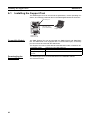
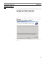
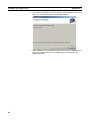
Installing the Support Tool . . . . . . . . . . . . . . . . . . . . . . . . . . . . . . . . . . . . . . . . . . . . . . . . . .
82
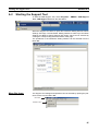
6-2
Starting the Support Tool. . . . . . . . . . . . . . . . . . . . . . . . . . . . . . . . . . . . . . . . . . . . . . . . . . . .
85
6-3
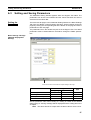
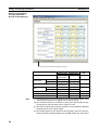
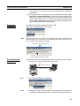
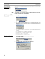
Setting and Saving Parameters . . . . . . . . . . . . . . . . . . . . . . . . . . . . . . . . . . . . . . . . . . . . . . .
87
6-4
Monitoring . . . . . . . . . . . . . . . . . . . . . . . . . . . . . . . . . . . . . . . . . . . . . . . . . . . . . . . . . . . . . . .
92
6-5
Other Settings . . . . . . . . . . . . . . . . . . . . . . . . . . . . . . . . . . . . . . . . . . . . . . . . . . . . . . . . . . . .
96
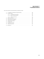
SECTION 7
Communications . . . . . . . . . . . . . . . . . . . . . . . . . . . . . . . . . . .
99
7-1
CompoWay/F Communications Specifications . . . . . . . . . . . . . . . . . . . . . . . . . . . . . . . . . . .
100
7-2
Frame Structure . . . . . . . . . . . . . . . . . . . . . . . . . . . . . . . . . . . . . . . . . . . . . . . . . . . . . . . . . . .
101
7-3
Details of Services . . . . . . . . . . . . . . . . . . . . . . . . . . . . . . . . . . . . . . . . . . . . . . . . . . . . . . . . .
109
7-4
Read Controller Information . . . . . . . . . . . . . . . . . . . . . . . . . . . . . . . . . . . . . . . . . . . . . . . . .
112
7-5
Read Controller Attributes. . . . . . . . . . . . . . . . . . . . . . . . . . . . . . . . . . . . . . . . . . . . . . . . . . .
114
7-6
Read Controller Status. . . . . . . . . . . . . . . . . . . . . . . . . . . . . . . . . . . . . . . . . . . . . . . . . . . . . .
115
7-7
Echoback Test . . . . . . . . . . . . . . . . . . . . . . . . . . . . . . . . . . . . . . . . . . . . . . . . . . . . . . . . . . . .
116
7-8
Operation Command . . . . . . . . . . . . . . . . . . . . . . . . . . . . . . . . . . . . . . . . . . . . . . . . . . . . . . .
117
7-9
Response Code List . . . . . . . . . . . . . . . . . . . . . . . . . . . . . . . . . . . . . . . . . . . . . . . . . . . . . . . .
118
7-10 ASCII List . . . . . . . . . . . . . . . . . . . . . . . . . . . . . . . . . . . . . . . . . . . . . . . . . . . . . . . . . . . . . . .
119
SECTION 8
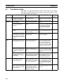
Error Processing . . . . . . . . . . . . . . . . . . . . . . . . . . . . . . . . . . . 121
8-1
Troubleshooting . . . . . . . . . . . . . . . . . . . . . . . . . . . . . . . . . . . . . . . . . . . . . . . . . . . . . . . . . . .
122
8-2
Seven-segment Error Codes. . . . . . . . . . . . . . . . . . . . . . . . . . . . . . . . . . . . . . . . . . . . . . . . . .
123
8-3
Clearing Errors. . . . . . . . . . . . . . . . . . . . . . . . . . . . . . . . . . . . . . . . . . . . . . . . . . . . . . . . . . . .
125
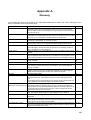
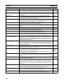
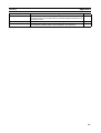
Appendices
A
Glossary . . . . . . . . . . . . . . . . . . . . . . . . . . . . . . . . . . . . . . . . . . . . . . . . . . . . . . . . . . . . . . . .
129
B
List of Operations . . . . . . . . . . . . . . . . . . . . . . . . . . . . . . . . . . . . . . . . . . . . . . . . . . . . . . . . .
133
Revision History . . . . . . . . . . . . . . . . . . . . . . . . . . . . . . . . . . . 137
vi
About this Manual:
This manual describes the installation and operation of the S8M Digital Multicircuit Protector and
includes the sections described below.
Please read this manual carefully and be sure you understand the information provided before
attempting to install or operate the S8M Digital Multicircuit Protector. Be sure to read the precautions
provided in the following section.
Precautions provides general precautions for using the S8M Digital Multicircuit Protector and related
devices.
Section 1 introduces the features and functions of the S8M Digital Multicircuit Protector and concepts
related to its operation.
Section 2 identifies the S8M Digital Multicircuit Protector’s components, provides specifications, and
describes the basic functions.
Section 3 describes how to install and wire the S8M Digital Multicircuit Protector.
Section 4 describes how to set the S8M’s various parameters.
Section 5 describes how to connect the branch outputs and test operation.
Section 6 describes how to install and operate the S8M Support Tool.
Section 7 describes how to use S8M communications.
Section 8 provides information on troubleshooting problems that may occur with the S8M Digital Multicircuit Protector.
The appendices provide a glossary of terms related to the S8M and flowcharts of S8M key operations.
!WARNING Failure to read and understand the information provided in this manual may result in personal injury or death, damage to the Product, or Product failure. Please read each section
in its entirety and be sure you understand the information provided in the section and
related sections before attempting any of the procedures or operations given.
vii
viii
Read and Understand this Manual
Please read and understand this manual before using the product. Please consult your OMRON
representative if you have any questions or comments.
Warranty and Limitations of Liability
WARRANTY
OMRON's exclusive warranty is that the products are free from defects in materials and workmanship for a
period of one year (or other period if specified) from date of sale by OMRON.
OMRON MAKES NO WARRANTY OR REPRESENTATION, EXPRESS OR IMPLIED, REGARDING NONINFRINGEMENT, MERCHANTABILITY, OR FITNESS FOR PARTICULAR PURPOSE OF THE PRODUCTS. ANY
BUYER OR USER ACKNOWLEDGES THAT THE BUYER OR USER ALONE HAS DETERMINED THAT THE
PRODUCTS WILL SUITABLY MEET THE REQUIREMENTS OF THEIR INTENDED USE. OMRON DISCLAIMS ALL
OTHER WARRANTIES, EXPRESS OR IMPLIED.
LIMITATIONS OF LIABILITY
OMRON SHALL NOT BE RESPONSIBLE FOR SPECIAL, INDIRECT, OR CONSEQUENTIAL DAMAGES,
LOSS OF PROFITS OR COMMERCIAL LOSS IN ANY WAY CONNECTED WITH THE PRODUCTS,
WHETHER SUCH CLAIM IS BASED ON CONTRACT, WARRANTY, NEGLIGENCE, OR STRICT
LIABILITY.
In no event shall the responsibility of OMRON for any act exceed the individual price of the product on which
liability is asserted.
IN NO EVENT SHALL OMRON BE RESPONSIBLE FOR WARRANTY, REPAIR, OR OTHER CLAIMS
REGARDING THE PRODUCTS UNLESS OMRON'S ANALYSIS CONFIRMS THAT THE PRODUCTS
WERE PROPERLY HANDLED, STORED, INSTALLED, AND MAINTAINED AND NOT SUBJECT TO
CONTAMINATION, ABUSE, MISUSE, OR INAPPROPRIATE MODIFICATION OR REPAIR.
Application Considerations
SUITABILITY FOR USE
OMRON shall not be responsible for conformity with any standards, codes, or regulations that apply to the
combination of products in the customer's application or use of the products.
At the customer's request, OMRON will provide applicable third party certification documents identifying
ratings and limitations of use that apply to the products. This information by itself is not sufficient for a
complete determination of the suitability of the products in combination with the end product, machine,
system, or other application or use.
The following are some examples of applications for which particular attention must be given. This is not
intended to be an exhaustive list of all possible uses of the products, nor is it intended to imply that the uses
listed may be suitable for the products:
• Outdoor use, uses involving potential chemical contamination or electrical interference, or conditions or
uses not described in this manual.
• Nuclear energy control systems, combustion systems, railroad systems, aviation systems, medical
equipment, amusement machines, vehicles, safety equipment, and installations subject to separate
industry or government regulations.
• Systems, machines, and equipment that could present a risk to life or property.
Please know and observe all prohibitions of use applicable to the products.
NEVER USE THE PRODUCTS FOR AN APPLICATION INVOLVING SERIOUS RISK TO LIFE OR
PROPERTY WITHOUT ENSURING THAT THE SYSTEM AS A WHOLE HAS BEEN DESIGNED TO
ADDRESS THE RISKS, AND THAT THE OMRON PRODUCTS ARE PROPERLY RATED AND INSTALLED
FOR THE INTENDED USE WITHIN THE OVERALL EQUIPMENT OR SYSTEM.
PROGRAMMABLE PRODUCTS
OMRON shall not be responsible for the user's programming of a programmable product, or any
consequence thereof.
ix
Disclaimers
CHANGE IN SPECIFICATIONS
Product specifications and accessories may be changed at any time based on improvements and other
reasons.
It is our practice to change model numbers when published ratings or features are changed, or when
significant construction changes are made. However, some specifications of the products may be changed
without any notice. When in doubt, special model numbers may be assigned to fix or establish key
specifications for your application on your request. Please consult with your OMRON representative at any
time to confirm actual specifications of purchased products.
DIMENSIONS AND WEIGHTS
Dimensions and weights are nominal and are not to be used for manufacturing purposes, even when
tolerances are shown.
PERFORMANCE DATA
Performance data given in this manual is provided as a guide for the user in determining suitability and does
not constitute a warranty. It may represent the result of OMRON's test conditions, and the users must
correlate it to actual application requirements. Actual performance is subject to the OMRON Warranty and
Limitations of Liability.
ERRORS AND OMISSIONS
The information in this document has been carefully checked and is believed to be accurate; however, no
responsibility is assumed for clerical, typographical, or proofreading errors, or omissions.
x
Safety Precautions
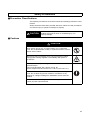
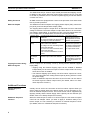
■ Precaution Classifications
The following conventions are used to indicate and classify precautions in this
manual.
Always heed the information provided with them. Failure to heed precautions
can result in injury to people or damage to property.
CAUTION
Indicates a potentially hazardous situation which, if not
avoided, may result in minor or moderate injury or in
property damage.
■ Cautions
CAUTION
Minor electric shock, fire, or Product failure may occasionally
occur. Do not disassemble, modify, or repair the Product or touch
interior of the Product.
Minor burns may occasionally occur. Do not touch the Product
during power is being supplied or immediately after power is
turned OFF.
Fire may occasionally occur. Tighten terminal screws to the
specified torque.
Power input terminals: M4 1.08 N·m (9.6 in. lb.)
Branch output terminals: M3.5 0.8 to 1.0 N·m (7.2 to 8.8 in. lb.)
Minor electric shock, fire, or Product failure may occasionally
occur. Do not allow any pieces of metal or conductors or any
clippings or cuttings resulting from installation work to enter the
Product.
The Product will be damaged. Do not incorrectly connect the
polarity of power input terminals.
xi
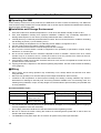
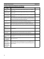
Precautions for Safe Use
■ Operating the S8M
Unlike ordinary mechanical circuit protectors, the S8M does not have contacts for switching. The S8M uses
semiconductor relays to switch the circuits ON/OFF and cut off the outputs. Read and understand the following
features before operating the S8M.
■ Installation and Storage Environment
1.
2.
Store the Product at an ambient temperature of –25 to 65°C and relative humidity of 25% to 90%.
Poor heat dissipation resulting from improper installation conditions may occasionally deteriorate or
damage internal parts. Do not use any mounting method other than a standard one.
3. Internal parts may occasionally be deteriorated or broken. Do not use the Product in conditions exceeding
the derating (in portion (1) of the derating curve).
4. The surrounding air temperature for UL 508 listing and UL 60950-1 recognition is 50°C.
5. Use the Product where the relative humidity is 25% to 85%.
6. Do not use the Product where it would be subjected to direct sunlight.
7. Do not use the Product where it would be subjected to the possibility of penetration of liquid, foreign
substance, or corrosive gas.
8. Do not use the Product where it would be subjected to shock or vibration. A device such as a contact
breaker may be a vibration source. Install the Product as far as possible from external devices.
Additionally, install a PFP-M End Plate on each side of the Product.
9. If the Product is used in an area with excessive electronic noise, be sure to separate the Product as far as
possible from the noise sources.
10. Tripping performance depends on the ambient operating temperature. Use the Product within the derating
curve (page xiii).
■ Wiring
•
•
•
Minor electric shock during operation may occasionally occur. Always attach the terminal cover when
using the S8M.
Minor fire may possibly occur. Ensure that input and output terminals are wired correctly.
Increases in the temperature of internal parts resulting from heating of wiring materials may result in
deterioration or damage to internal parts. Use wiring materials suitable to the current being used. The
following wiring materials, torque, and strip length are recommended to prevent heating and possible fires
in wiring materials.
Recommended Wire Types
Terminals
Power input terminals
Wiring materials
AWG14 (2.081 mm2) × 2 Solid,
Stranded
Branch output terminals AWG16 to 20
2
(1.309 to 0.517 mm )
Other terminals
AWG18 to 26
(0.823 to 0.129 mm2)
•
•
•
•
xii
Torque
1.08 N·m (9.6 in. lb.)
Strip length
8 to 10 mm
0.8 to 1.0 N·m (7.2 to 8.8 in. lb.) 6 to 7 mm
---
10 mm
It is conceivable that internal parts may be deteriorated or damaged. Do not repeatedly perform tripping or
recovery operations more than necessary.
Do not apply more than 100 N force to the terminal block when tightening screws.
Be sure to remove the sheet covering the Product for machining before power-ON so that it does not
interfere with heat dissipation.
The S8M takes a DC power input. Do not connect AC power to the power input terminals.
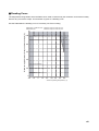
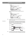
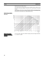
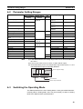
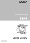
■ Derating Curve
The temperature range within which the S8M can be used is restricted by the maximum current that normally
flows for any one branch output. This restriction is given as a derating curve.
Use the S8M within the derating curve. If necessary, use forced cooling.
Maximum applied current for any one branch output (%)
S8M-CP04 or S8M-CP04-R: Maximum output current of 4.0 A
S8M-CP04-RS:
Maximum output current of 3.8 A
100
(1)
80
60
40
20
0
−20 −10
0
10
20
30
40
50
60
Ambient operating temperature (°C)
xiii
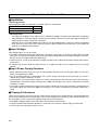
Precautions for Correct Use
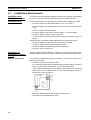
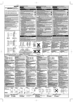
■ Installation
• Mounting Direction
Always install the S8M on a DIN Rail. For details, refer to 3-2 Installation.
Standard horizontal mounting
Upward-facing mounting
OK
Incorrect
Other mounting directions
Incorrect
• Mounting Space
The long-term reliability of the S8M can be increased by installing it properly and sufficiently considering
heat dissipation. Install the S8M so that the air flow circulates around it, because the S8M is designed to
radiate heat by means of natural air circulation.
Although two or more S8M Multicircuit Protectors can be installed side by side, they must be separated
from sources of heat, such as the switching power supply installed to the input side, by the distances
given in 3-1 Installation Environment.
■ Input Voltage
Input voltage range: 19.2 to 26.4 VDC
• The S8M provides abnormal voltage protection. All branch outputs will be cut off if the input voltage exceeds
28.8 VDC. This function, however, does not protect loads and internal parts from high voltages in all cases.
Be sure the input voltage is within the rated range.
• Outputs may be cut off by the abnormal voltage protection with loads that generate reverse peak electromotive force.
• A voltage drop occurs within the S8M. Be sure to consider the effect of the voltage drop on the output
voltage.
■ Input Power Supply Selection
• When selecting a power supply, be sure to add the S8M’s internal power consumption (about 10 W) to the
power consumption of the loads.
• The overcurrent protection characteristics of the power supply connected to the input side can cause a
voltage drop, possibly resulting in a cutoff.
• If the capacity of the input power supply is too small compared with the load, the overcurrent protection
characteristics of the power supply can prevent the S8M from starting or can cause a voltage drop, possibly
resulting in a cutoff.
• If secondary voltage of the power supply rises or falls too slowly, the overcurrent protection characteristics of
the power supply can prevent the S8M from starting or can cause a voltage drop, possibly resulting in a
cutoff.
■ Tripping Performance
There are two tripping types that can be used to detect output current characteristics: Standard detection
(overcurrents lasting 80 ms are cutoff within 100 ms) and Instantaneous detection (overcurrents lasting 20 ms
are cutoff within 10 ms). Set the best tripping output current characteristics.
• If the S8M is tripped, always remove the cause first and then reset the S8M.
• If using a load with a fixed power operation, a cutoff may occur when the power supply is turned OFF.
• The accuracy of the tripping current is ±0.3 A.
xiv
■ Startup Delay
To prevent cutoffs caused by large surge currents when the equipment starts, the S8M has a startup delay that
disables the tripping operation for 70 ms after the semiconductor relay turns ON.
• The startup delay will not operate when a relay or other device is used for ON/OFF control on the output side
of the S8M, so a tripping operation may occasionally occur.
■ Withstand Voltage Test
The S8M is designed to withstand 500 VAC for 1 minute between the power input terminals and all branch
output terminals, between all signal output terminals and all external tripping input terminals, between all
signal output terminals and all communications terminals, and between all external tripping input terminals and
all communications terminals.
Note • The S8M may possibly be damaged from the impulse voltage if a testing device switch is used to
abruptly apply or shut off 500 VAC. Increase the applied voltage gradually using the voltage
adjustment on the testing device.
• Always short the specified terminals so that the voltage is applied to all of the terminals at the same
time.
• The power input terminals and branch output terminals are not isolated. Do not perform dielectric
strength tests between the input and output terminals.
■ Voltage Display
The voltage detection function monitors the voltage at the power input terminals. Measure the voltage at the
branch outputs to confirm that the output voltage is correct.
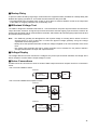
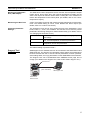
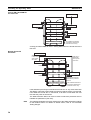
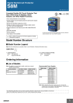
■ Series Connections
An S8M cannot be connected in series to another S8M’s output and branch outputs cannot be connected in
series.
• Do not connect S8Ms in series.
Incorrect
+
AC/DC
power supply
+
S8M
S8M
−
−
• Do not connect S8M branch outputs in series.
Incorrect
+
+
AC/DC
power supply
S8M
−
−
+
S8M
−
Incorrect
+
+
AC/DC
power supply
S8M
−
−
+
−
xv
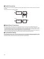
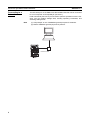
■ Parallel Connections
An S8M cannot be connected in parallel with another S8M’s output and branch outputs cannot be connected
in parallel.
• Do not connect branch outputs in parallel.
Incorrect
+
AC/DC
power supply
+
S8M
−
−
+
S8M
−
Incorrect
+
+
AC/DC
power supply
S8M
−
−
+
−
■ Backup Device Connections
Observe the following precautions when using a backup device, such as one from OMRON's S8T Series.
• If a backup device is connected to an S8M branch output, the backup current will be supplied to other
branches through internal circuits and internal parts may also be deteriorated or damaged. When using a
backup device with the S8M, connect the backup device to the power input side.
• When connecting a backup device to the S8M input side, the backup time will be shorter than normal due to
internal power consumption. Always confirm the backup time when using a backup device.
■ Terminal Block Plating
The tripping alarm output, alarm output, over-temperature output, and external tripping input terminals, as well
as the connecting sections of the communications terminals, are gold-plated. If connection failures occur, we
recommend making connections with the wires made from the same material.
xvi
Using this Manual
■ Notation in this Manual
There are three models of S8M Digital Multicircuit Protectors covered in this manual: the S8M-CP04 (model
without an RS-232C port), S8M-CP04-R, and S8M-CP04-RS (UL Class 2 output model). These are collectively referred to as the S8M. The functions and specifications described in this manual are shared by all three
models, unless differences are mentioned specifically.
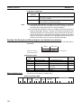
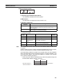
■ Notation of Setting Data
Setting data codes and contents are displayed in seven-segment display characters, as shown in the following
diagram.
V
xvii
xviii
SECTION 1
Features and Functions
This section describes the features and functions of the S8M.
1-1
Overview of Features and Functions. . . . . . . . . . . . . . . . . . . . . . . . . . . . . . . .
2
1-2
S8M Operations and Operating Modes. . . . . . . . . . . . . . . . . . . . . . . . . . . . . .
7
1-3
Table of Basic Functions . . . . . . . . . . . . . . . . . . . . . . . . . . . . . . . . . . . . . . . . .
10
1-4
S8M Operating Procedure. . . . . . . . . . . . . . . . . . . . . . . . . . . . . . . . . . . . . . . .
11
1
Section 1-1
Overview of Features and Functions
1-1
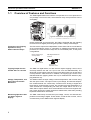
Overview of Features and Functions
The S8M Digital Multicircuit Protector incorporates four circuit protectors in
one package. The four 24-VDC, semiconductor relay circuit protectors can be
set digitally.
Typical mechanical circuit protectors
Unlike mechanical circuit protectors, the S8M is equipped with the following
functions that use digital processing and provide a variety of advantages.
Connection and Tripping
Operations Using
Semiconductor Relays
The four branch outputs are independent of each other and are connected/cut
off by semiconductor relays. In comparison to traditional mechanical circuit
protectors, the semiconductor relays are not consumable parts, so they have
a long lifetime.
Normal contact-style
circuit protector
S8M Digital Multicircuit
Protector
Overcurrent
tripping device
Overcurrent
detection circuit
Tripping Output Current
Can Be Set in 0.1-A Units
The S8M is a digital device, so each branch output's tripping current can be
set freely between 0.5 and 4.0 A (0.5 to 3.8 A for the S8M-CP04-RS). The
abnormal current tripping value and overcurrent alarm value can be set as the
circuit protector's rated currents. In addition, the tripping type can be set to
standard detection (tripping within 100 ms) or instantaneous detection (tripping within 20 ms).
Voltage, Temperature, and
Run Time Can Also Be
Monitored
The S8M monitors the input voltage, internal temperature, and run time, along
with the input current. The input current, input voltage, and internal temperature measurements are continuously converted from analog to digital and
these values, as well as the run time, are compared to preset parameters. If a
value exceeds the corresponding set value, the output will be cut off or an
alarm will be output and the error will be indicated on the seven-segment display. These functions increase the device's added value, while also providing
important maintenance information.
Monitoring Operation with
the Seven-segment
Display
The S8M continuously converts the input voltage, current, and internal temperature from analog to digital. These values, as well as the run time, can be
checked easily on the S8M's seven-segment display.
2
Section 1-1
Overview of Features and Functions
Error Display and Tripping
Functions
When the input voltage, current, internal temperature, or run time exceeds the
set value, the error code will be displayed on the seven-segment display and
the branch output will be cut off or an alarm will be output and the branch output will remain connected. Error codes are displaying in order of their severity,
so the source of the error can be isolated quickly.
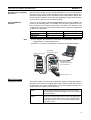
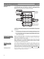
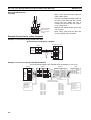
Three S8M Models
Available
There are three models of the S8M Digital Multicircuit Protector available, as
shown in the following table. The models share the same performance and
basic functions such as tripping and alarms, but differ in the internal circuit
configuration (see note 2) and communications ports. Select the appropriate
model for your application.
Model
Note
RS-232C port
Redundant tripping circuits
S8M-CP04-R
S8M-CP04-RS
Yes
Yes
No
Yes
S8M-CP04
No
No
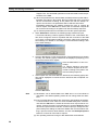
(1) The Support Tool cannot be used with the S8M-CP04, which is not
equipped with a communications port.
(2) Refer to 2-2 Internal Configuration for internal circuit block diagrams.
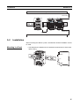
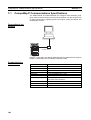
AC/DC Power Supply
S8M Digital
Multicircuit Protector
S8M Support Tool
The S8M-CP04-R/-RS
can be connected.
Branch outputs 1 to 4
Basic Functions
Tripping Functions
The branch output is cut off when an abnormal voltage or abnormal current is
detected. In this case, the tripping alarm output will be turned OFF and the
corresponding error code will be shown on the seven-segment display. (For
details, refer to 2-4 Basic Function Details.)
Abnormal voltage
tripping
Abnormal current
tripping
When the power supply voltage exceeds 28.8 V, all of the
branch outputs will be cut off by the semiconductor relays.
The S8M system monitors the voltage, so it is not necessary
to set parameters.
When a branch output's current exceeds the set value, that
output is cut off by its semiconductor relay. The tripping type
for abnormal current detection can be set to standard detection (tripping within 100 ms) or instantaneous detection (tripping within 20 ms).
3
Section 1-1
Overview of Features and Functions
The S8M-CP04-RS (UL Class 2 output model) has redundant tripping circuits.
In addition to the regular abnormal current tripping function (0.5 to 3.8 A) that
is set with a parameter, there is a built-in system tripping circuit that detects
currents over 4.0 A.
Safety Functions
All S8M models are equipped with a short-circuit protection fuse and thermal
fuse to provide protection.
External Outputs
The S8M has 3 external outputs: the Tripping Alarm Output (TRP), Alarm Output (ALM), and Over-temperature Output (TMP).
The Tripping Alarm Output is output when an abnormal current or abnormal
voltage is detected. The Alarm Output is output when there is an overcurrent,
overvoltage, undervoltage, or excessive run time. The Over-temperature Output is output when the temperature exceeds the rated temperature.
Tripping Functions Using
External Signals
Tripping Alarm
Output (TRP)
• An abnormal voltage over 28.8 V was
detected.
• A current exceeding the abnormal current tripping value was detected.
The output status is
retained when power is
interrupted but can reset
with the reset operation.
Alarm Output
(ALM)
• A voltage below the undervoltage
alarm value was detected.
• A voltage over the overvoltage alarm
value was detected.
• A current over the overcurrent alarm
value was detected.
• The run time exceeded the run time
value.
This output can be reset
with the reset operation. If
the alarm is cleared when
the power is turned ON,
the output will be reset.
Over-temperature Output
(TMP)
A temperature exceeding the over-temperature output value was detected.
The output is reset automatically when the temperature falls to 3°C below
the over-temperature output value.
Branch outputs can be forcibly cut off by turning ON the External Tripping
Input (TRG).
• Tripping using the External Tripping Input can be enabled or disabled
independently for each branch output. A branch output will be cut off only
when this function is enabled.
• The External Tripping Input directly cuts off a branch output's DC circuit,
so it acts even faster than cutting off the output by turning OFF the normal
AC power supply.
• When a shutdown sequence has been set, this function can be used to
set a time lag for the branch output cutoff. (For details, refer to 2-6 Shutdown Sequence Function.)
Additional Functions
Startup Sequence
Function
A delay can be set for the connection of the four branch outputs. When you
want to apply a startup delay to the branch output, it is not necessary to construct an external sequence circuit. The inrush current can be suppressed by
applying a delay and the Power Supply Unit's capacity can be reduced. (For
details, refer to 2-5 Startup Sequence Function.)
Shutdown Sequence
Function
When an external input is used to cut off an output, the four branch outputs'
cutoff can be delayed. When you want to apply a shutdown delay to the
branch output, it is not necessary to construct an external sequence circuit.
(For details, refer to 2-6 Shutdown Sequence Function.)
4
Section 1-1
Overview of Features and Functions
Monitoring Temperature
Rise (TMP Output)
The S8M has a built-in temperature sensor and the Over-temperature Output
(TMP) will be turned OFF when the internal temperature exceeds the set
value. This output can also be used to start a cooling fan or air conditioner to
reduce the temperature in the control panel. (For details, refer to 2-4-3 Overtemperature Output.)
Monitoring the Run Time
A Run Time Value can be set and used for periodic maintenance of the equipment. The default setting is 0.0 kh, which disables the alarm output. (For
details, refer to 2-4-4 Run Time Alarm.)
Protecting Parameter
Settings
The Protection Level can be set to restrict access to the parameters. Three
levels, levels 0, 1, and 2, are available. This function can be used to prevent
parameters from being changed or deleted inadvertently. (For details, refer to
4-4 Changing the Protection Level.)
Protection level 0
Protection level 1
Protection level 2
There are no restrictions on reading and changing the parameter settings.
Permits only reading and changing of the input voltage, current, internal temperature, and run time parameters.
Permits only reading of the input voltage, current, internal
temperature, and run time parameters.
The default setting is protection level 1.
Support Tool
Available
S8M Support Tool is available and can be connected to the S8M-CP04-R and
S8M-CP04-RS. The Support Tool simplifies system startup and maintenance
because it allows the user to set the various parameters, monitor operation,
save settings data, and copy parameters to other S8M Multicircuit Protectors.
The Support Tool can be downloaded from OMRON's home page free of
charge. (For details on the Support Tool, refer to SECTION 6 Support Tool.)
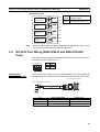
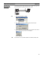
RS-232C Port
RS-232C cable
(User-assembled)
S8M Support Tool
S8M-CP04-R
S8M-CP04-RS
5
Section 1-1
Overview of Features and Functions
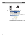
Connecting to a
Network
The RS-232C port on the S8M-CP04-R and S8M-CP04-RS can be connected
to a host computer via CompoWay/F (see note 1).
FINS commands (see note 2) can be used to perform operations over the network, such as reading settings data, sending operating commands, and
switching setting levels.
Note
(1) CompoWay/F is one of OMRON's general-purpose FA networks.
(2) FINS is OMRON's general-purpose FA protocol.
RS-232C cable
6
Section 1-2
S8M Operations and Operating Modes
1-2
S8M Operations and Operating Modes
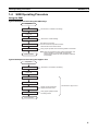
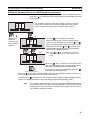
The S8M has 3 operating modes: Run Mode, Setting Mode, and Test Mode.
Run Mode
Setting Mode
Test Mode
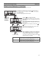
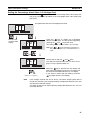
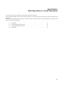
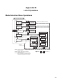
Note
Changing the
Operating Mode
Turning the Power ON for
the First Time
Branch outputs are connected while monitoring the input voltage, current, internal temperature, and run time. The monitored PV is displayed on the seven-segment display and can
be read with key operations.
This mode is used to set parameters. Branch output connections are the same as in Run Mode. The S8M automatically
starts in Setting Mode when the S8M is used for the first time.
This mode is used to test operation. The factory default setting for all outputs is OFF, so the branch outputs being used
must be turned ON in Test Mode.
When the Support Tool is connected, the S8M can be operated and parameters can be set/changed regardless of the S8M’s operating mode.
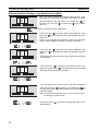
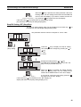
The operating mode can be changed from the Mode Selection Menu using
the Up and Down Keys.
• A newly purchased S8M will automatically enter Setting Mode when it is
turned ON for the first time. Refer to SECTION 4 Parameter Settings for
details on setting parameters in Setting Mode.
• When starting operation or setting branch output connections after setting
the parameters, return to the Mode Selection Menu and switch to Test
Mode. Refer to SECTION 5 Trial Operation to Actual Operation for details
on the operations in Test Mode.
• When changing to Run Mode after completing the trial run, return to the
Mode Selection Menu and switch to Run Mode. If the power is turned
OFF while the S8M is in Test Mode, the S8M will enter Test Mode again
the next time that the power is turned ON. In this case, all branch outputs
will be OFF (not connected).
Power ON
Mode Selection Menu
Select Run Mode run (RUN)
Run Mode
+
Setting Mode
Select Setting Mode set (SET)
+
Press for 3 s
Press for 3 s
Select Test Mode tst (TST)
Test Mode
+
Press for 3 s
Select Protection Level prt (PRT)
Initialize Parameters ini (INI)
The Initialize Parameters
command is displayed in
protection level 0 only.
7
Section 1-2
S8M Operations and Operating Modes
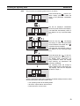
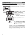
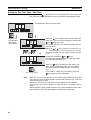
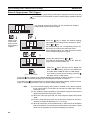
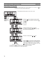
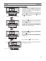
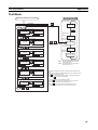
Normal Power-ON
Procedure
If the S8M has been turned ON already, it will enter Run Mode or Test Mode
the next time that power is turned ON. If the S8M was in Test Mode when the
power went OFF, it will start in Test Mode. If it was in a mode other than Test
Mode when the power went OFF, it will start in Run Mode.
Power ON
S8M was not
in Test Mode
when power
went OFF.
S8M was in
Test Mode
when power
went OFF.
Mode Selection Menu
Run Mode
+
Select Run Mode run (RUN)
Press for 3 s
Select Setting Mode set (SET)
Setting Mode
Select Test Mode tst (TST)
+
Test Mode
+
Press for 3 s
Select Protection Level prt (PRT)
Initialize Parameters ini (INI)
Press for 3 s
Test Mode cannot be
selected in protection
level 2.
The Initialize Parameters
command is displayed in
protection level 0 only.
In addition to selecting the operating mode, the Mode Selection Menu can be
used to select the protection level (see note 1) and initialize the parameters
(see note 2).
Note
(1) The Protection Level function can restrict parameter read/write access to
one of three levels. For details, refer to 4-4 Changing the Protection Level.
(2) The Initialize Parameters function restores all of the S8M's parameter settings to their default values. For details on default values, refer to 4-2 Parameter Setting Ranges.
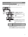
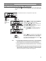
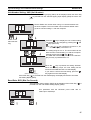
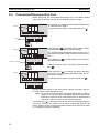
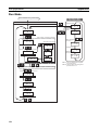
Automatic Operation
after Power ON
When a 24 VDC power supply is connected to the input terminal block, the
S8M performs self-diagnostics. If no errors are detected, the S8M immediately starts connecting the branch outputs.
Branch outputs will not be connected (ON) if they were not set to ON in Test
Mode. Furthermore, if the startup sequence function (see 2-5 Startup
Sequence Function) has been set, the outputs will be connected in order
according to their corresponding set times.
Operation in Run
Mode
In Run Mode, the S8M continuously converts the input voltage, current, run
time, and internal temperature from analog to digital and compares these
present values to the set values (both user-set parameters and system set
values). These values can be read on the S8M's seven-segment display and
the displayed value can be switched with the Up Key ( ) and Down Key ( ).
Tripping Operation
When the voltage or current is abnormal, the branch output is cut off and the
Tripping Alarm Output (TRP) is turned OFF.
8
S8M Operations and Operating Modes
Section 1-2
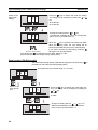
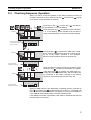
Alarm Operation
When the converted input voltage, current, internal temperature, or run time
exceeds the set value, the output will be cut off or an alarm will be output and
the error indicated on the Alarm Output (ALM) will be turned OFF. (The Overtemperature Output (TMP) will also be turned OFF if the temperature exceeds
the set value.)
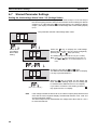
Operation in Setting
Mode
Setting Mode can be used to set the various parameters, but the S8M connects to branch outputs in Setting Mode, just as it does in Run Mode. When
an error is detected, branch outputs will be cut off and external signals will be
output, just as they are in Run Mode.
Note
Operation in Test
Mode
If an error occurs in Setting Mode, the error code is not displayed
and the error cannot be reset. To reset the error, first switch the operating mode to Run Mode and then reset the error.
In Test Mode, each branch output can be set to ON or OFF (connected or disconnected). In addition, the operation of the startup sequence and shutdown
sequence can be verified.
• The output connection status does not change when the operating mode
is switched from Run Mode to Test Mode.
• If a branch output is OFF (disconnected) in Test Mode, it will not go ON
even when the operating mode is changed to Run Mode.
If you want to set unused branch outputs to OFF, set those outputs to OFF
in Test Mode before switching to Run Mode.
• If the power is turned OFF while the S8M is in Test Mode, the S8M will
start in Test Mode the next time that the power is turned ON.
Note
Note
When an error occurs in Test Mode, branch outputs will be cut off
and external signals will be output, just as they are in Run Mode.
On the other hand, the error code will not be displayed and the error
cannot be reset. To reset the error, first switch the operating mode
to Run Mode and then reset the error.
(1) When the S8M is shipped from the factory, all branch outputs are set to
OFF (disconnected). A newly purchased S8M will automatically enter
Setting Mode when it is turned ON for the first time. After setting the parameters, switch to Test Mode, connect the branch outputs that will be
used, and then switch to Run Mode.
(2) If a branch output is OFF (disconnected) when the mode is changed from
Test Mode to Run Mode, it will not be connected (ON) in Run Mode.
(3) If the power is turned OFF while the S8M is in Test Mode, the S8M will
start in Test Mode the next time that the power is turned ON, but all
branch outputs will be OFF.
Operation with
Support Tool
Connected
The S8M will be operational even when parameters are being set with the
Support Tool.
If data is downloaded from the Support Tool (parameters transferred from the
Support Tool to the S8M), the parameters in the S8M will be updated immediately.
9
Section 1-3
Table of Basic Functions
1-3
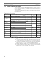
Table of Basic Functions
There are three ways for the S8M's tripping function to operate: tripping by
user-set parameters, tripping by the S8M's system monitor, and tripping by
external operation.
There are three outputs: the Tripping Alarm Output, Alarm Output, and Overtemperature Output.
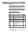
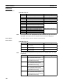
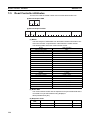
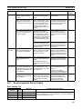
Tripping/Alarm Functions
Setting
Operating range
Parameter
settings
Outputs cut off
External
output
Error code
displayed
Abnormal voltage
tripping
Automatically trips for voltage over
28.8 VDC for more than 10 ms.
None
All branch outputs TRP output
OFF
A10
Short-circuit current tripping
9.0 A for more than 10 ms
None
Individual branch
output
Individual branch
output
Individual branch
output
TRP output
OFF
TRP output
OFF
TRP output
OFF
A11
ALM output
OFF
A20/Voltage
(alternating)
Abnormal current
tripping
(See note 2.)
S8M-CP04-RS only: Trips within 0.5 None
s for current over 4.0 A. (See note 1.)
S8M-CP04-R and S8M-CP04: 0.5 to 4.0 A
(in 0.1 A units)
S8M-CP04-RS: 0.5 to 3.8 A (in 0.1 A units)
Overvoltage alarm
20.0 to 28.8 VDC (in 0.1 V units)
None
Undervoltage alarm 18.0 to 26.4 VDC (in 0.1 V units)
None
Overcurrent alarm
(See note 3.)
S8M-CP04-R and S8M-CP04: 0.5 to 4.0 A
(in 0.1 A units)
S8M-CP04-RS: 0.5 to 3.8 A (in 0.1 A units)
None
ALM output
OFF
A21/Voltage
(alternating)
A22/Current
(alternating)
Run time
0.0 to 99.9 kh
(99,900 hours ≅11.4 years, see note 4)
None
ALM output
OFF
A23/Time
(alternating)
Over-temperature
output
25 to 80°C
Set value + 1°C for 1 s continuously
None
TMP output
OFF
A30/Temperature (alternating)
External tripping
input
External input signal (TRG) ON
---
TRG
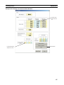
Support Tool
Click the Connect Output Buttons for the desired outputs in the
Present Values Window.
---
---
Note
Specified output (See note 5.)
A11/Current
(alternating)
A11/Current
(alternating)
(1) There are redundant overcurrent protection functions in the S8M-CP04RS.
(2) The tripping function operates within 100 ms when the S8M is set to standard detection and within 20 ms when it is set to instantaneous detection.
(3) The alarm is output within 100 ms when the S8M is set to standard detection and within 20 ms when it is set to instantaneous detection.
(4) Run time alarms are disabled when the time parameter is set to 0.0 kh.
(5) The TRG signal applies only to the branch outputs for which the external
tripping input is enabled. For details, refer to page 67.
10
Section 1-4
S8M Operating Procedure
1-4
S8M Operating Procedure
Using the S8M
Typical Startup Procedure Using the S8M's Keys
Preparation
Installation and wiring
See Section 3 Installation and Wiring.
Power ON
Set parameters
Trial run in Test Mode
See Section 4 Initial Settings.
See Section 5 Trial Run.
Connect the branch outputs that will be
used and then switch to Run Mode.
Verify operation
Verify proper operation while monitoring status in Run Mode.
Actual operation
Note: When turning ON the power, setting parameters, and
testing operation in a new S8M, the parameter
settings will be saved only when the S8M is switched
to Run Mode.
Typical Startup Procedure Using the Support Tool
Preparation
Installation and wiring
See Section 3 Installation and Wiring.
Power ON
Connect Support Tool
Set parameters
See Section 6 Support Tool.
Trial run
Verify operation
Always connect the branch
outputs that will be used.
Verify proper operation while
monitoring status.
Actual operation
11
S8M Operating Procedure
Section 1-4
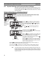
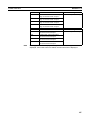
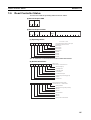
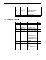
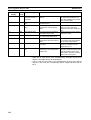
Summary of Application Objectives and Settings
Desired objective/
Settings
usage
Use as a circuit
In Setting Mode, set the tripping current value (C-V) for the branch output being
breaker with overcur- used and set the abnormal current tripping detection setting (C-T) to standard
rent tripping.
detection (USU).
Use as a circuit
breaker for short-circuit current protection.
Output an alarm
when output is cut off
due to overcurrent.
Output an alarm
before output is cut
off due to overcurrent.
Details
56, 58
In Setting Mode, set the tripping current value (C-V) for the branch output being
used and set the abnormal current tripping detection setting (C-T) to instantaneous
detection (INS).
Take the alarm signal from the Tripping Alarm Output (TRP) terminal. When an output is cut off, the seven-segment display will show error code A11 and the TRP output will go OFF.
In Setting Mode, set the overcurrent alarm value (A-V) for the branch output being
used and set the overcurrent alarm detection setting (A-T) to standard detection
(USU) or instantaneous detection (INS). Take the alarm signal from the Alarm Output (ALM) terminal. When an overcurrent is detected, the seven-segment display
will show error code A22 and the ALM output will go OFF.
Detect power supply In Setting Mode, set the overvoltage alarm value (V-O). Take the alarm signal from
overvoltage.
the Alarm Output (ALM) terminal. When an overvoltage is detected, the seven-segment display will show error code A20 and the ALM output will go OFF.
Detect a drop in
In Setting Mode, set the undervoltage alarm value (V-U). Take the alarm signal
power supply voltfrom the Alarm Output (ALM) terminal. When an overvoltage is detected, the
age.
seven-segment display will show error code A21 and the ALM output will go OFF.
Apply a separate
In Setting Mode, set the startup sequence (UPS).
time lag when connecting each branch
output.
56, 58, 40
Apply a separate
In Setting Mode, set the shutdown sequence (DWS) and enable the External Triptime lag when cutting ping Input (TRG).
off each branch output.
65, 66, 31
58, 59, 40
61
61, 40
64, 30
Perform a system
inspection after a
fixed run time.
In Setting Mode, set the desired run time (TIM). Take the alarm signal from the
71, 30 41
Alarm Output (ALM) terminal. When the preset run time is reached, the seven-segment display will show error code A23 and the ALM output will go OFF.
Reset the run time.
Monitor temperature
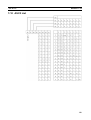
rise in control panel
and prevent overheating.
In Setting Mode, select the Clear Run Time command (CLR).
71
In Setting Mode, set the over-temperature output value (TMP). Take the signal from 61, 28, 41
the Over-temperature Output (TMP) terminal and use that signal to operate a fan or
air conditioner.
Restrict read/write
access of parameters to prevent mistaken operations.
Ensure normal operation for other
devices connected to
a power supply to
which a device with a
short-circuit is connected. (Prevent
voltage drops due to
short-circuits.)
Select the protection level setting (PRT) from the Mode Selection Menu and set the 54
desired protection level.
12
To achieve this, extra current capacity is required in the Power Supply Unit con39, 79
nected to the S8M. Select a Power Supply Unit with a current capacity that is 10 to
12 A higher than the maximum current supply to the connected devices. Use the
total current display in Run Mode to confirm if the selected Power Supply Unit satisfies this condition.
SECTION 2
Specifications and Functions
This section provides the specifications of the S8M and describes special S8M functions.
2-1
Component Names and Functions . . . . . . . . . . . . . . . . . . . . . . . . . . . . . . . . .
14
2-2
Internal Configuration . . . . . . . . . . . . . . . . . . . . . . . . . . . . . . . . . . . . . . . . . . .
16
2-3
Specifications . . . . . . . . . . . . . . . . . . . . . . . . . . . . . . . . . . . . . . . . . . . . . . . . .
18
2-4
Basic Function Details . . . . . . . . . . . . . . . . . . . . . . . . . . . . . . . . . . . . . . . . . .
22
2-4-1
Current Protection Functions . . . . . . . . . . . . . . . . . . . . . . . . . . . . . .
22
2-4-2
Overvoltage/Undervoltage Protection Function . . . . . . . . . . . . . . . .
26
2-4-3
Over-temperature Output . . . . . . . . . . . . . . . . . . . . . . . . . . . . . . . . .
28
2-4-4
Run Time Alarm . . . . . . . . . . . . . . . . . . . . . . . . . . . . . . . . . . . . . . . .
30
2-5
Startup Sequence Function . . . . . . . . . . . . . . . . . . . . . . . . . . . . . . . . . . . . . . .
30
2-6
Shutdown Sequence Function . . . . . . . . . . . . . . . . . . . . . . . . . . . . . . . . . . . . .
31
13
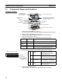
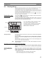
Section 2-1
Component Names and Functions
2-1
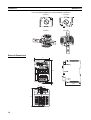
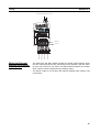
Component Names and Functions
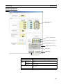
Component Names
4. Output Terminals
5. External Tripping
Input Terminal
1. Power Input Terminals
6. Seven-segment
Display
12. RS-232C Port Terminal Block
(The S8M-CP04 is not equipped
with an RS-232C port.)
7. Indicators
8. Mode Key
11. Reset Key
10. Down Key
9. Up Key
3. Status Indicators
2. Branch Output Terminals
1. Power Input Terminal Block (+V and −V)
Connect to the 24 VDC input power supply. (The terminal screws are M4.)
2. Branch Output Terminal Block (+V and −V)
Connect to each branch output. (The terminal screws are M3.5.)
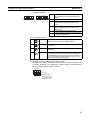
3. Status Indicators (Red or Green)
Indicate the connection and cutoff status for each branch output.
Not lit
Not connected
Lit green
Connected
Set to OFF (disconnected) or forcibly cut off by command.
Connected normally.
Flashing
green
Not connected
In the startup sequence and waiting for connection.
Lit red
Flashing red
Cut off
Cut off
Cut off due to an error.
Cut off by the redundant protection circuit required
for a UL Class 2 output (S8M-CP04-RS only).
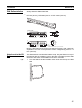
4. External Output Terminals and 5. External Tripping Input Terminal
TRP
+ −
ALM
+ −
TMP
+ −
TRG
+ −
4
Wire hole
Release button
When removing a
wire, press here to
release the lock.
5
TRP
Tripping Alarm
Output
OFF to indicate when an abnormal voltage or current was
detected and the output was cut
off. (Transistor OFF)
ALM
Alarm Output
OFF to indicate that the input voltage, current, or run time exceeded
the alarm value. (Transistor OFF)
TMP
Over-temperature Output
TRG
External Tripping
Input
OFF to indicate that the temperature exceeded the over-temperature output value. (Transistor OFF)
Can be used to send an input signal from an external device to cut
off a branch output.
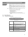
6. Seven-segment Display (Red)
Displays measured values or set values on a 3-digit LED display.
14
Section 2-1
Component Names and Functions
7. Indicators (Orange)
1
2
3
4
V
Branch output indicators
A
kh °C
s
Unit indicators
1 to 4
V
An indicator will light or flash when the display is related to the corresponding branch
output.
Lit when displaying the input voltage.
A
Lit when displaying the output current.
Flashes when displaying the peak output
current.
kh
Lit when displaying the run time. The sevensegment display shows the time in 0.1-kh
(100-h) units.
°C
s
Lit when displaying the temperature.
Lit when setting the startup sequence time or
shutdown sequence time.
8. to 11. Operation Keys
8
Mode Key
Used to set the parameter being displayed, clear the
peak hold current value, and register settings.
9
Up Key
Used to move to different setting modes or to increment
a set value.
10
Down Key
Used to move to different setting modes or to decrement
a set value.
Reset Key
Used to clear an alarm output or connect a branch output that was cut off by an error or external tripping input.
The Reset Key cannot connect an output that was set to
OFF (not connected) in Test Mode or cut off by a command via RS-232C communications.
11
RST
12. RS-232C Port Terminal Block (RD, SD, and SG)
Connect to the communications lines (RS-232C). The terminal block has
screwless terminals. The S8M-CP04 (model without communications)
does not have these RS-232C terminals.
SD RD SG
Wire hole
Release button
When removing a
wire, press here to
release the lock.
15
Section 2-2
Internal Configuration
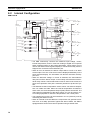
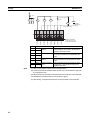
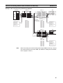
2-2
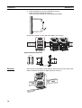
Internal Configuration
S8M-CP04-R
Current-detection resistor
Thermal fuse
Cutoff
circuit
Fuse
+V
+V
Voltage
detection
Display
circuit
Switches
DC branch output 1
Temperature
detection
−V
Current-limiting circuit
DC input
power supply
Power supply
circuit
Processing
circuit
Thermal fuse
Current-detec- Cutoff
tion resistor
circuit
Fuse
+V
DC branch output 2
RS-232C
SD
communica- RD
tions terminals SG
Tripping alarm output +
(TRP) −
−V
Current-limiting circuit
Communications circuit
Current-detec- Cutoff
tion resistor
circuit
Thermal fuse
Fuse
+V
DC branch output 3
Alarm output +
(ALM) −
−V
Current-limiting circuit
Over-temperature output +
(TMP) −
External tripping input +
(TRG) −
Current-detection resistor
Thermal fuse
Cutoff
circuit
Fuse
+V
DC branch output 4
Current-limiting circuit
−V
−V
• The S8M continuously converts the measured input voltage, current,
internal temperature, and run time from analog to digital and compares
these measured values to the preset parameters. These values can be
read on the S8M's seven-segment display or monitored remotely from the
Support Tool connected via the RS-232C port.
• When an error is detected, the branch output will be cut off or an alarm
will be output. The error code and PV will be displayed alternately on the
seven-segment display. The information can also be read from the Support Tool.
• When an abnormal voltage or current is detected, the semiconductor
relay will cut off the branch output. In the unlikely event that the semiconductor relay cannot cut off an abnormal current or short-circuit current, the
short-circuit protection fuse (8.0 A minimum) will blow to protect the system.
• The S8M has a built-in temperature sensor, which can detect a temperature rise inside the S8M. When the internal temperature exceeds the
alarm value, the Over-temperature Output (TMP) will be turned OFF. The
TMP output is independent of the alarm output, so it can be used to control cooling equipment to reduce the temperature in the control panel.
• The equipment's run time can be monitored in 0.1-kh (100-hour) units by
measuring the S8M's run time.
• When an internal circuit has failed, the components can generate excessive heat. As a safety precaution against this kind of failure, the S8M is
equipped with a function that cuts off operation using a thermal fuse.
16
Section 2-2
Internal Configuration
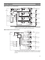
S8M-CP04-RS (UL Class 2 Output Model)
Cutoff
circuit
Current-detection resistor
Current-detec- Cutoff
tion resistor
circuit
Thermal fuse
+V
Voltage
detection
Display
circuit
Switches
Fuse
Temperature
detection
−V
Current-limiting circuit
DC input
power supply
Power supply
circuit
Current-detec- Cutoff
circuit
tion resistor
Current-detection resistor
Cutoff
circuit
Processing
circuit
+V
DC branch output 1
Thermal fuse
Fuse
+V
DC branch output 2
−V
Current-limiting circuit
RS-232C
SD
communica- RD
tions terminals SG
Communications circuit
Cutoff
circuit
Tripping alarm output +
(TRP) −
Current-detec- Cutoff
tion resistor
circuit
Current-detection resistor
Thermal fuse
Fuse
+V
DC branch output 3
Alarm output +
(ALM) −
−V
Current-limiting circuit
Over-temperature output +
(TMP) −
Cutoff
circuit
External tripping input +
(TRG) −
Current-detection resistor
Current-detec- Cutoff
circuit
tion resistor
Thermal fuse
Fuse
+V
DC branch output 4
−V
Current-limiting circuit
−V
In addition to the regular cutoff circuits (cutoffs for abnormal current, abnormal
voltage, etc.), the UL Class 2 output model has a cutoff circuit that detects
only overcurrents of 4.0 A or higher and cuts off the output.
S8M-CP04 (Model without Communications)
Current-detecCutoff
tion resistor
circuit
Thermal fuse
Fuse
+V
+V
Voltage
detection
Display
circuit
Switches
Temperature
detection
DC branch output 1
−V
Current-limiting circuit
DC input
power supply
Power supply
circuit
Processing
circuit
Current-detec- Cutoff
tion resistor
circuit
Thermal fuse
Fuse
+V
DC branch output 2
−V
Current-limiting circuit
Tripping alarm output+
(TRP)−
Thermal fuse
Current-detec- Cutoff
tion resistor
circuit
+V
DC branch output 3
Alarm output +
(ALM) −
−V
Current-limiting circuit
Over-temperature output+
(TMP)−
External tripping input +
(TRG)−
Fuse
Current-detec- Cutoff
circuit
tion resistor
Thermal fuse
Fuse
+V
DC branch output 4
Current-limiting circuit
−V
−V
This model has the same basic functions and configuration as the standard
model, but does not have an RS-232C port so it cannot connect to the Support Tool.
17
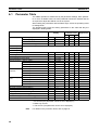
Section 2-3
Specifications
2-3
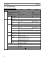
Specifications
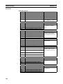
Ratings and Characteristics
Item
Model
S8M-CP04
Number of branches
4
I/O char- Rated input voltage
acteristics
Allowable input current
24 VDC (19.2 to 26.4 VDC)
S8M-CP04-RS
17.0 A max.
16.0 A max.
4.0 A
3.8 A
Internal voltage drop
0.5 VDC max. (at 4.0 A)
0.7 VDC max. (at 3.8 A)
Output leakage current
10 mA max.
Power consumption
4 branches output,
normal operation
10 W max. (at 4.0 A)
4 branches output,
outputs cut off
3 W max.
Maximum shutoff output current (per
branch)
Functions
S8M-CP04-R
Tripping func- Abnormal voltage
tions
tripping
Alarm functions
28.8 V (fixed), Tripping Alarm Output (TRP) OFF
Abnormal current
tripping
Setting range: 0.5 to 4.0 A (in 0.1-A units), Tripping
Alarm Output OFF
Tripping Alarm Output
(TRP)
Transistor output
30 VDC max. and 50 mA max., Leakage current: 0.1 mA max., Residual voltage: 2
V max.
Setting range: 0.5 to 3.8 A
(in 0.1-A units), Tripping
Alarm Output OFF
Overvoltage alarm
Setting range: 20.0 to 28.8 V (in 0.1-V units), Alarm Output (ALM) OFF
Undervoltage alarm
Setting range: 18.0 to 26.4 V (in 0.1-V units), Alarm Output (ALM) OFF
Overcurrent alarm
Setting range: 0.5 to 4.0 A (in 0.1-A units), Alarm Output (ALM) OFF
Run time alarm
Setting range: 0.0 to 99.9 kh (in 0.1-kh units), Alarm Output (ALM) OFF
(The alarm output is disabled if the time is set to 0.0 kh.)
Alarm Output (ALM)
Transistor output
30 VDC max. and 50 mA max., Leakage current: 0.1 mA max., Residual voltage: 2
V max.
Over-temper- Over-temperature
ature function
Over-temperature
Output (TMP)
Display functions
15 W max.
Input voltage display/
detection
Setting range: 0.5 to 3.8 A
(in 0.1-A units), Alarm Output (ALM) OFF
Setting range: 25 to 80°C, Over-temperature Output
Transistor output
30 VDC max. and 50 mA max., Leakage current: 0.1 mA max., Residual voltage: 2
V max.
Display range:17.0 to 30.0 V
Display accuracy: 2% rdg ±1 digit max.
Output current display/ Branch output display range: 0.0 to 10.0 A
detection
Peak output current display range: 0.0 to 10.0 A
Total current display range: 0.0 to 40.0 A
Display accuracy: 5% FS (4 A) ±1 digit max.
18
Run time
Display range: 0.0 to 99.9 kh
Display accuracy: 2% rdg ±1 digit max.
Temperature display/
detection
Display range: −10 to 100°C
Display accuracy: 2°C ±1 digit max.
External Tripping Input (TRG)
19.2 to 30 VDC, minimum signal width: 20 ms, tripping after input within 10 ms + the
shutdown sequence set time
Startup sequence
A delay can be enabled/disabled for each branch output, setting range: 0.0 to 99.9 s
in 0.1-s units.
Shutdown sequence
A delay can be enabled/disabled for each branch output, setting range: 0.0 to 99.9 s
in 0.1-s units.
Communications
None
Sampling period
1 ms
Supported (RS-232C)
Section 2-3
Specifications
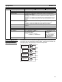
Item
Other
Model
S8M-CP04
S8M-CP04-R
S8M-CP04-RS
Ambient operating temperature
Refer to the derating curve (no condensation or icing allowed).
Storage temperature
−25 to 65°C
Ambient operating humidity
25% to 85% (storage: 25% to 90%)
Withstand voltage
1.0 kVAC for 1 min between all charged sections and all non-charged sections
(detection current: 20 mA)
500 VAC for 1 min between all I/O and I/O signals/communications (detection current: 20 mA)
500 VAC for 1 min between all I/O signals and communications (detection current:
20 mA)
500 VAC for 1 min between input signals and all output signals (detection current:
20 mA)
Insulation resistance
100 MΩ min. at 500 VDC between all charged sections and all non-charged sections
100 MΩ min. at 500 VDC between all I/O and I/O signals/communications
100 MΩ min. at 500 VDC between all I/O signals and communications
Vibration resistance
No abnormality after 10 to 55 Hz at 0.375-mm single amplitude for 2 h each in 3
directions.
Shock resistance
No abnormality after 150 m/s2 3 times each in 6 directions.
Conducted EMI
Conforms to EN 61204-3 Class B.
Radiated EMI
Conforms to EN 61204-3 Class B.
Safety standards
UL: UL 508 (Listing), UL 60950-1
cUL: CSA C22.2 No. 107-1
cUR: CSA No. 60950-1
EN/VDE: EN 50178 (= VDE0160)
EN 60950-1 (= VDE0805 Teil 1)
Weight
400 g max.
External Output and
External Tripping
Input Specifications
UL: UL 508 (Listing, Class
2: Per UL 1310),
UL60950-1
cUL: CSA C22.2 No. 107-1
cUR: CSA No. 60950-1
EN/VDE: EN 50178
(= VDE0160), EN 60950-1
(= VDE0805 Teil 1)
The S8M has 3 external outputs, the Tripping Alarm Output (TRP), Alarm Output (ALM), and Over-temperature Output (TMP), as well as an External Tripping Input (TRG). Each of these I/O circuits is independent.
TRP+
Tripping Alarm
Output circuit
Alarm Output
circuit
TRP−
ALM+
ALM−
Overtemperature
Output circuit
TMP+
External
Tripping Input
circuit
TRG+
TMP−
TRG−
19
Section 2-3
Specifications
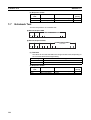
I/O Circuit Configuration
Name
Tripping Alarm Output (TRP), Alarm
Output (ALM), and
Over-temperature
Output (TMP)
Circuit configuration
Output circuit
I/O specifications
30 VDC and 50 mA max.
Transistor output
Internal Circuit Configuration of the Alarm
and Over-temperature Outputs
From internal power supply circuit
+ pole
Signal from CPU
− pole
External Tripping
Input (TRG)
Input circuit
Internal Circuit Configuration
of the External Tripping Input
19.2 to 30.0 VDC
Minimum signal width: 10 ms
+ pole
− pole
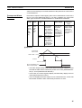
Note
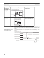
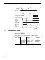
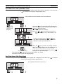
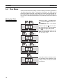
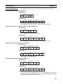
Example Operation of the
Alarm Output (ALM)
When a branch output is cut off with the External Tripping Input, it cuts off
power to the branch output even faster than turning OFF the S8M's power
supply.
This example shows the ALM output operation when an undervoltage alarm
occurs.
Undervoltage alarm value
Power supply voltage
Branch output current
Branch output voltage
Alarm Output (ALM)
ON
(conducting)
OFF
(not conducting)
ON
(conducting)
Reset signal
3 s min.
20
Section 2-3
Specifications
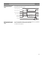
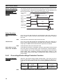
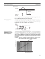
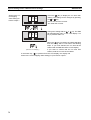
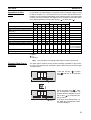
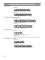
Example Operation of the
Tripping Alarm Output
(TRP)
This example shows the TRP output operation when an overcurrent alarm or
abnormal current tripping occurs.
Tripping (cutoff) current value
Power supply voltage
Overcurrent alarm value
Branch output current
Branch output voltage
Alarm Output (ALM)
ON
(conducting)
OFF
(not conducting)
Tripping Alarm
Output (ALM)
ON
(conducting)
OFF
(not conducting)
ON
(conducting)
ON
(conducting)
Reset signal
3 s min.
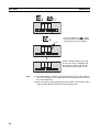
Example Operation of the
Over-temperature Output
(TMP)
The Over-temperature Output is reset automatically when the temperature
falls to 3°C below the over-temperature output value.
For details, refer to page 28.
21
Section 2-4
Basic Function Details
2-4
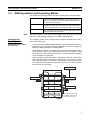
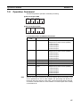
2-4-1
Basic Function Details
Current Protection Functions
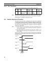
Abnormal Current
Tripping
A different current tripping value can be set for each branch output. Set the
current tripping values between 0.5 and 4.0 A (in 0.1 A units) with the S8MCP04 and S8M-CP04-R, or between 0.5 and 3.8 A (in 0.1 A units) with the
S8M-CP04-RS.
The abnormal current tripping type can be set to standard detection (tripping
within 100 ms) or instantaneous detection (tripping within 20 ms).
When the S8M detects an abnormal current, that branch output is cut off by its
semiconductor relay. When the output is cut off, the error code (A11) and
present current are displayed alternately on the seven-segment display and
the Tripping Alarm Output (TRP) is turned OFF.
To reset the alarm, press the Reset Key 15 s after the alarm occurred.
Setting Default
range
value
0.5 to
4.0 A
(0.5 to
3.8 A in
the
S8MCP04RS)
4.0 A
(3.8 A
in the
S8MCP04RS)
Tripping
type
Operation
Error code and
alarm output
Standard
When a current
higher than the
set value is
detected, the
branch output is
cut off within
100 ms.
Instantaneous
When a current
higher than the
set value is
detected, the
branch output is
cut off within 20
ms.
The error code
(A11) and current are displayed
alternately on
the seven-segment display
and the Tripping
Alarm Output
(TRP) is turned
OFF.
Conditions
required to
reset
The Reset Key
can be used to
reset the alarm
once 15 s have
elapsed after
the alarm.
Abnormal current
value
Current
Standard detection: 100 ms
Instantaneous detection: 20 ms
Tripping Alarm
Output (TRP)
Note
22
15 s min.
Reset possible
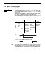
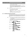
After sampling and converting each branch output's current every 1 ms, the
S8M processes the values in the CPU and controls the branch output cutoffs.
This method achieves high-speed, high-accuracy tripping. In addition, to minimize the effects of excessive currents caused by short-circuits, the S8M is
equipped with built-in current-limiting circuits. Consequently, there is a region
in which the current is limited, as shown in the current tripping characteristics
graphs.
Section 2-4
Basic Function Details
Current actually flowing
Current value
Converted digital value
1 ms sampling period
Time
Example sampling chart
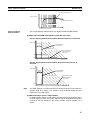
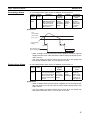
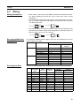
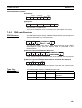
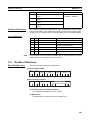
Current Tripping
Characteristics
The current tripping characteristics vary slightly in different S8M models.
■
S8M-CP04-R and S8M-CP04 (Model without RS-232C Port)
Current Tripping Characteristics When Standard Detection Is Selected
Time (ms)
Setting
range
Characteristics
when steady
Tripping region
Current-limiting by
internal circuits
(See note.)
100
20
0.5
4
6
12
Current (A)
Current Tripping Characteristics When Instantaneous Detection Is
Selected
Time (ms)
Setting
range
Characteristics
when steady
Tripping region
Current-limiting by
internal circuits
(See note.)
20
0.5
Note
4
12
Current (A)
The S8M contains a current-restricting circuit that prevents a current above a
specific value from flowing. The current is thus restricted during the time
required to cut off the output.
■
S8M-CP04-RS (UL Class 2 Output Model)
In addition to the regular current tripping function that cuts off operation at the
user-set tripping current, the Class 2 output model is equipped with a tripping
circuit that cuts off operation if the branch output's current exceeds 4.0 A
(fixed).
23
Section 2-4
Basic Function Details
Current Tripping Characteristics When Standard Detection Is Selected
Time (ms)
Setting
range
Characteristics
when steady
Tripping region
Current-limiting by
internal circuits
(See note.)
100
20
0.5
3.8
12
6
Current (A)
Current Tripping Characteristics When Instantaneous Detection Is
Selected
Time (ms)
Setting
range
Characteristics
when steady
Tripping region
Current-limiting by
internal circuits
(See note.)
20
0.5
Note
Startup Delay
3.8
12
Current (A)
The S8M contains a current-restricting circuit that prevents a current above a
specific value from flowing. The current is thus restricted during the time
required to cut off the output.
Normally, a large inrush current may run through the system when equipment
starts. Tripping operation can be disabled for a short time after the semiconductor relay goes ON in order to prevent this inrush current from being
detected as an abnormal current and cutting off operation. This temporary
disabling of the tripping function is called the startup delay.
Power supply
voltage
Branch output
voltage
No cutoff during startup delay
even if set value is exceeded.
Tripping current
value
Branch output
current
Startup delay (70 ms)
Tripping Alarm
Output (TRP)
OFF (open)
Note
24
100 ms max. (standard detection)
ON (closed)
OFF (open)
The startup delay disables the tripping operation for the specified period of
time. The inrush current during this time can be displayed as the peak output
current. The S8M, however, contains a current-restricting circuit, so the peak
Section 2-4
Basic Function Details
value is not necessarily an accurate measure of the peak inrush current of the
connected device.
Overcurrent Alarm
Function
Each branch output's current tripping value can be set between 0.5 and 4.0 A
(0.5 to 3.8 A in the S8M-CP04-RS) in 0.1 A units. In addition, the overcurrent
alarm type can be set to standard detection or instantaneous detection.
Setting Default
range
value
0.5 to
4.0 A
(0.5 to
3.8 A in
the
S8MCP04RS)
■
4.0 A
(3.8 A
in the
S8MCP04RS)
Alarm
type
Operation
Standard
When the current is higher
than the set
value continuously for 80 ms
or more, the
alarm is output
within 100 ms.
Instantaneous
When the current is higher
than the set
value continuously for 10 ms
or more, the
alarm is output
within 20 ms.
Error code and
alarm output
Conditions
required to
reset
The error code
(A22) and current are displayed
alternately on
the seven-segment display
and the Alarm
Output (ALM) is
turned OFF.
The Reset Key
can be used to
reset the alarm
once the current is 0.3 A or
more below the
set value.
Operation
Overcurrent
alarm value
Alarm value − 0.3 A
Current
100 ms or 20 ms
Error code display and
Alarm Output (ALM)
500 ms
Reset possible
• The Alarm Output (ALM) will be turned OFF if the branch output's current
exceeds the alarm value continuously for 80 ms or more (standard detection) or 10 ms (instantaneous detection).
• In this case, the seven-segment display will alternately display the error
code (A22) and present current.
• The error display and Alarm Output can be cleared when the current has
been below the alarm value continuously for 500 ms or more.
25
Section 2-4
Basic Function Details
Alarm and Tripping
Operation When
Overcurrent/
Abnormal Current
Occurs
The following example shows the alarm and tripping operation when the overcurrent alarm value < abnormal current tripping value. It is also possible to set
the overcurrent alarm value > abnormal current tripping value.
Power supply
voltage
Abnormal tripping current value
Overcurrent alarm value
Branch output
current
Branch output
voltage
Alarm Output
(ALM)
ON
OFF
ON
Tripping Alarm
Output (TRP)
ON
OFF
ON
Reset signal
3s
Safety Functions
Short-circuit Protection
Fuse
Note
Thermal Fuse
If the fuse blows, that branch output cannot be used.
If an error occurs that prevents the semiconductor relay from cutting off a
branch output and the temperature of the S8M's internal resistors rises abnormally high, the S8M's thermal fuse will blow to prevent a fire hazard.
Note
Safety When Cycling
Power from Test Mode
2-4-2
If an error occurs that prevents the semiconductor relay from cutting off a
branch output's current, the short-circuit protection fuse will blow to protect
the circuit.
If the fuse blows, that circuit cannot be used.
If the S8M is turned OFF in Test Mode, all branch outputs will be disconnected
when the power is turned ON again. This is because the connection/disconnection settings have not been completed, so all outputs are disconnected to
ensure safety. After completing connection/disconnection settings in Test
Mode, always change to Run Mode or Setting Mode before turning OFF the
power supply.
Overvoltage/Undervoltage Protection Function
Abnormal Voltage
Tripping
When the input power supply voltage exceeds 28.8 V (see note), all of the
branch outputs will be cut off and the seven-segment display will indicate error
code A10. It is not necessary for the user to set any parameters for this function.
Tripping
operation
28.8 V min.
20 ms max.
Note
26
Seven-segment
display
Alternately displays
error code A10 and
the voltage.
Outputs
The Tripping Alarm
Output (TRP) is
turned OFF.
The voltage is measured at the power input terminals.
Conditions required
to reset
Voltage below 28.5 V
and 15 s elapsed
after output is cut off.
Section 2-4
Basic Function Details
Overvoltage Alarm
An overvoltage alarm value can be set between 20.0 and 28.8 V.
Setting Default
range
value
20.0 to
28.8 V
■
28.8 V
Operation
Sevensegment
display
When the voltage is Alternately
higher than the alarm displays
value continuously
error code
for 80 ms or more,
A20 and the
the alarm is output
voltage.
within 100 ms.
Outputs
Conditions
required to
reset
The Alarm Voltage below
Output
the alarm
(ALM) is
value −0.3 V
turned
continuously
OFF.
for at least
500 ms.
Operation
V-O:
Overvoltage
alarm value
(V-O) −0.3 V
Power supply
voltage
100 ms
500 ms
Error display and
Alarm Output (ALM)
Reset possible
• When a voltage exceeding the alarm value is applied, the seven-segment
display will show error code A20 and the Alarm Output (ALM) will go OFF
within 100 ms.
• The error display and Alarm Output can be reset when the voltage has
been below the alarm value −0.3 V for 500 ms or more.
Undervoltage Alarm
An overvoltage alarm value can be set between 18.0 and 26.4 V.
Setting Default
range value
18.0 to
26.4 V
■
20.0 V
Operation
Sevensegment
display
Outputs
Conditions
required to
reset
When the voltage is
lower than the alarm
value continuously for
80 ms or more, the
alarm is output within
100 ms.
Alternately
displays
error code
A21 and the
voltage.
The Alarm
Output
(ALM) is
turned OFF.
Voltage
above the
alarm value
+0.3 V continuously for at
least 500 ms.
Operation
• When a voltage below the alarm value is applied, the seven-segment display will show error code A21 and the Alarm Output (ALM) will go OFF
within 100 ms.
• The error display and Alarm Output can be reset when the voltage has
been above the alarm value +0.3 V for 500 ms or more.
27
Section 2-4
Basic Function Details
Power supply
voltage
(V-U) +0.3 V
V-U: Undervoltage
alarm value
500 ms
100 ms
Error display and
Alarm Output (ALM)
Reset possible
Undervoltage alarm value
Power supply
voltage
Branch output
current
Branch output
voltage
Alarm Output
(ALM)
ON
OFF
ON
Reset signal
3 s min.
2-4-3
Over-temperature Output
When the temperature exceeds the set value continuously for more than 1 s,
the seven-segment display will show error code A30 and the Over-temperature Output (TMP) will go OFF.
The error display and Over-temperature Output are reset automatically when
the temperature has been below the set value − 3°C for more than 5 s.
Setting Default
range
value
25 to
80°C
28
80°C
Operation
Sevensegment
display
The output is
Alternately
turned OFF when displays
the temperature is error code
higher than the
A30 and the
set value continu- temperature
ously for more
(°C).
than 1 s.
Outputs
Conditions
required to
reset
The OverReset automatitemperature cally when the
Output
temperature falls
(TMP) is
below the set
turned OFF. value − 3°C.
Section 2-4
Basic Function Details
■
Operation
t: Over-temperature
output value
(t-3)°C
Temperature (°C)
1s
5s
Error display and
Over-temperature
Output (TMP)
Automatic reset
The Over-temperature Output (TMP) operates independently of the other
external outputs. This output can be used to start an exhaust fan or air conditioner to reduce the temperature in the control panel.
Example Application
The output is normally closed (ON) and goes OFF when there is an error, so
receive the TMP output through an auxiliary relay. In addition, the output will
go ON momentarily when the power is turned ON, so receive the output
through a time-delay relay. (For details, refer to page 41.)
S8M
TMP
TR
X
COM
TR
IM
Fan, etc.
24 VDC
The internal temperature of the S8M is displayed. This is not necessarily the
same as the ambient temperature of the S8M or the temperature inside the
control panel. The difference between the internal temperature of the S8M
and the ambient temperature depends on the current flowing through the
S8M. Consider this difference in the application. The following graph provides
reference information on the displayed internal temperature and the ambient
temperature.
Conditions: The same current was output from all branch outputs in a constant-temperature bath held at a constant temperature.
At 0.5 A
At 3.5 A
Ambient temperature (°C)
Relationship between
Control Panel
Temperature and S8M’s
Internal Temperature
80
70
60
50
40
30
20
10
0
−10
−20
−20
0
20
40
60
80
Displayed temperature (°C)
29
Section 2-5
Startup Sequence Function
2-4-4
Run Time Alarm
An alarm can be output when the run time exceeds the alarm value.
Setting Default
range
value
0.0 to
0.0 kh
99.9 kh (See
note.)
Note
Operation
Sevensegment
display
An alarm is out- Alternately disput when the run plays error
time exceeds the code A23 and
alarm value.
the run time.
Outputs
The Alarm
Output
(ALM) is
turned OFF.
Conditions
required to
reset
Either set a
higher alarm
value or clear
the run time.
An alarm will not be output when the alarm value is set to 0.0 kh. Set the
alarm value to 0.0 kh (default value) when the run time alarm is not needed.
Refer to page 71 for details on clearing the run time.
2-5
Startup Sequence Function
The inrush current may cause a voltage drop if all of the branch outputs are
connected simultaneously and there is little spare capacity in the power supply or the loads connected to the branch outputs are capacitive loads. A significant voltage drop may cause an output to be cut off. In this case, a time delay
(see note) can be applied between the connections of the branch outputs to
minimize the voltage drop.
Note
(1) The time delay can be set between 0.0 and 99.9 s. (If the delay is set to
0.0 s, the startup sequence will not operate and the branch output will be
connected immediately.)
(2) The startup sequence is designed for the four branch outputs on one
S8M. It does not provide time synchronization between outputs on more
than one S8M.
After the power supply is turned ON and the self-diagnostics are performed,
the S8M will start connecting the branch output according to their preset startup sequence times.
Power supply
voltage
Branch output 1
voltage
Setting time
Branch output 2
voltage
Setting time
Branch output 3
voltage
Setting time
Branch output 4
voltage
Setting time
Self-diagnostics
(0.5 s min.)
30
Section 2-6
Shutdown Sequence Function
• The branch output's status indicator will flash green during the startup
sequence time until it is connected.
• The startup sequence's operation can be verified in Test Mode. For
details, refer to 5-3 Checking Sequence Operation.
• The startup sequence's operation can also be verified from the Support
Tool by clicking the Startup Sequence Button. (For details, refer to
page 94.)
Note
The startup sequence functions in the following processes:
• Connecting when power is turned ON
• Reconnecting during a reset operation
• Startup sequence executed by CompoWay/F command (Startup
Sequence)
• Simultaneous connection of all outputs in Test Mode
• Startup sequence executed from the Support Tool
2-6
Shutdown Sequence Function
When the S8M's input power supply is turned OFF, all of the branch outputs
are turned OFF (disconnected) simultaneously. On the other hand, when the
branch outputs are cut off by the external tripping input or communications, a
time delay (see note 1) can be applied between the branch output disconnections.
Note
(1) The time delay can be set between 0.0 and 99.9 s. (If the delay is set to
0.0 s, the startup sequence will not operate and the branch output will be
cut off immediately.)
(2) The shutdown sequence is designed for the four branch outputs on one
S8M. It does not provide time synchronization between outputs on more
than one S8M.
External tripping
input
Branch output 1
voltage
Setting time
Branch output 2
voltage
Setting time
Branch output 3
voltage
Setting time
Branch output 4
voltage
Setting time
Within 20 ms
31
Section 2-6
Shutdown Sequence Function
Note
(a) When operation is cut off due to an abnormal voltage (above
28.8 V), all of the branch outputs will be cut off simultaneously.
(b) The shutdown sequence function will operate on a branch output
only if the external tripping input is enabled for that branch output.
• The shutdown sequence's operation can be verified in Test Mode. For
details, refer to 5-3 Checking Sequence Operation.
• The shutdown sequence's operation can also be verified from the Support
Tool by clicking the Shutdown sequence Button on the Present Values
Window. (For details, refer to page 94.)
Note
The shutdown sequence functions in the following processes:
• Operation cut off by the external tripping input
• Shutdown sequence executed by CompoWay/F command (Startup
Sequence)
• Simultaneous cutoff of all outputs in Test Mode
• Shutdown sequence executed from the Support Tool
32
SECTION 3
Installation and Wiring
This section describes how to install and wire the S8M.
3-1
Installation Environment . . . . . . . . . . . . . . . . . . . . . . . . . . . . . . . . . . . . . . . . .
34
3-2
Installation. . . . . . . . . . . . . . . . . . . . . . . . . . . . . . . . . . . . . . . . . . . . . . . . . . . .
35
3-3
Wiring . . . . . . . . . . . . . . . . . . . . . . . . . . . . . . . . . . . . . . . . . . . . . . . . . . . . . . .
39
3-4
RS-232C Port Wiring (S8M-CP04-R and S8M-CP04-RS Only) . . . . . . . . . .
43
33
Section 3-1
Installation Environment
3-1
Installation Environment
Installation and
Wiring Precautions
To increase the S8M system's reliability and take full advantage of the S8M's
functions, observe the following precautions when installing the S8M.
Installation Site
Avoid locations with any of the following conditions when installing the S8M.
• Locations subject to a temperature below −10°C or over 60°C
• Locations subject to a humidity below 25% or over 90% (no condensation/
icing)
• Locations subject to direct sunlight
• Locations subject to exposure to liquids, debris, or corrosive gases
• Locations subject to severe shock or vibration
• Locations near equipment that generates strong high-frequency noise or
surges
Always enclose or protect the S8M sufficiently in the following locations.
• Locations subject to static electricity or other forms of noise.
• Locations subject to strong electromagnetic fields.
• Locations subject to possible exposure to radioactivity.
• Locations close to power lines.
Installation in
Cabinets or Control
Panels
When the S8M is being installed in a cabinet or control panel, always provide
suitable ambient conditions as well as access for operation and maintenance.
Ambient Temperature
The operating temperature range for the S8M is −10°C to 60°C. Observe the
following precautions.
• Provide enough space for good air flow.
• Do not install the S8M above equipment that generates a large amount of
heat, such as heaters, transformers, or high-capacity resistors.
• If the ambient temperature in the cabinet may exceed 60°C, install an
exhaust fan or air conditioner and use the Over-temperature Output to
operate the cooling equipment.
Control
panel
Fan
S8M
Vent
• Mount the S8M at least 20 mm away from heat sources.
• The S8M can be installed side-by-side.
34
Section 3-2
Installation
Wiring duct
75 mm min.
20 mm min.
75 mm min.
Wiring duct
3-2
Installation
When mounting the S8M in a panel, use DIN Rail. Surface installation cannot
be used.
Mounting in a Panel
• The S8M must be installed in the orientation shown below to ensure adequate cooling.
35
Section 3-2
Installation
• Do not install the S8M in any of the following orientations.
Incorrect
Incorrect
Incorrect
Incorrect
External Dimensions
75
115
4.1
8.7
4.35
94
36
86.5
Section 3-2
Installation
DIN Rail Installation
Always install the S8M on DIN Rail.
■
Recommended DIN Rail
PFP-50N (50 cm), PFP-100N (100 cm), or PFP-100N2 (100 cm)
PFP-100N2
16
28.25 × 4.5 oblong holes
4.5
30±0.3 27
15
25
10
25
25
1,000
10
25
PFP-100N/50N
15
24
29.2
1
1.5
7.3±0.15
4.5
35±0.3
15
25
10
25
25
1,000 (500)
(See note.)
10
25
27±0.15
15 (5)
1
(See note.)
Note: PFP-50N dimensions are given in parentheses.
Mount the DIN Rail with M4 screws in at least three places, with a maximum
separation of 210 mm (6 holes) between screws. The tightening torque is 1.2
N·m (10.8 in·lb).
Attachment to the DIN
Rail
The S8M attaches to the DIN Rail with one snap. Hang the S8M on the top of
the DIN Rail with the installation notch on the back of the S8M, pivot the S8M
downward, and press until the S8M locks securely on the Rail.
1,2,3...
1. Lower the S8M so that the installation notch hooks onto the top of the DIN
Rail.
37
Section 3-2
Installation
2. Press the S8M firmly onto the DIN Rail to mount it.
Press until the locks engage securely.
Press firmly, but carefully, to avoid damaging the S8M.
Attach an End Plate on each side of the S8M to fix it in place.
■
Recommended End Plate
10
PFP-M
6.2
M4 × 8
Pan-head
screw
50
1.8
1
35.5 35.3
1.8
11.5
10
M4 spring
washer
Removal
38
1.3
4.8
When removing the S8M from the DIN Rail, pull the lock lever down with a flatblade screwdriver and pivot the S8M upward to remove it.
Section 3-3
Wiring
3-3
Wiring
Wiring Precautions
• When wiring, cover the top of the S8M to prevent wire strands from entering. After completing the wiring, be sure to remove the cover to avoid
overheating.
• The power input terminals have M4 screws. Use the following crimp terminals on the power input wires and tighten the terminal screws to a torque
of 1.08 N·m (9.6 in·lb).
8 mm max.
8 mm max.
• The branch output terminals have M3.5 screws. Use the following crimp
terminals on the branch output wires and tighten the terminal screws to a
torque of 0.8 to 1.0 N·m (7.2 to 8.8 in·lb).
7 mm max.
Recommended Power
Supply Units
7 mm max.
The following OMRON Power Supply Units are recommended as the DC
power supply for the S8M.
Series
Model
Capacity
S8VS
S8VM
Selecting the Wire
Output
24-VDC output
current
S8VS-06024@@
S8VS-09024@@
60 W
90 W
2.5 A
3.75 A
S8VS-12024@@
S8VS-18024@@
120 W
180 W
5A
7.5 A
S8VS-24024@@
S8VM-05024@@
240 W
50 W
10 A
2.2 A
S8VM-10024@@
S8VM-15024@@
100 W
150 W
4.5 A
6.5 A
S8VM-30024C
S8VM-60024C
300 W
600 W
14.0 A
27.0 A
Refer to the following table when selecting wire to use for the power supply.
AWG
Cross-sec- Configurational area
tion
(wires/mm)
(mm2)
30
0.051
7/0.102
Voltage
Max. recommended current (A)
drop per A
UL1007
UL1015
(mV/m)
(300 V 80°C)
(600 V 105°C)
358
0.12
---
28
26
0.081
0.129
7/0.127
7/0.16
222
140
0.15
0.35
0.2
0.5
24
22
0.205
0.326
11/0.16
17/0.16
88.9
57.5
0.7
1.4
1.0
2.0
20
18
0.517
0.823
26/0.16
43/0.16
37.6
22.8
2.8
4.2
4.0
6.0
16
14
1.309
2.081
54/0.18
41/0.26
14.9
9.5
5.6
---
8.0
12.0
12
10
3.309
5.262
65/0.26
104/0.26
6.0
3.8
-----
22.0
35.0
39
Section 3-3
Wiring
Maximum Recommended Current:
The values listed in the table above are for bundles of up to 4 wires. If 5 or
more wires are bundled together, reduce the max. current to 80% of the listed
current.
The following chart shows only the relationship between the voltage drop per
meter and the current and wire length. Be sure that the current actually being
used does not exceed the max. recommended current.
Voltage drop (mV)
Voltage Drop per Meter
(UL1015 Heat-resistant
PVC Wire)
The current
shown is the allowed current.
In actual applications, use a
current below
the maximum
recommended
current.
Current (A)
Wiring the Power
Supply and Branch
Outputs
40
Use a DC power supply with sufficient capacity and little voltage fluctuation,
i.e., 24 VDC +10/−20%.
Section 3-3
Wiring
24 VDC Power Supply +10%/−20%
+ Terminal
Wiring the External
Outputs and External
Tripping Input
Branch output 4
Branch output 3
Branch output 2
Branch output 1
− Terminal
The TRP, ALM, and TMP outputs operate as normally closed outputs, which
are OFF when the power is OFF, ON during normal operation, and OFF when
an error has occurred. If you want to use these external outputs as normally
open outputs, invert the signals through auxiliary relays.
The branch output is cut off when the External Tripping Input (TRG) is ON
(connected).
41
Section 3-3
Wiring
TR
External Tripping
Input
X1 X2 X3
X3
X2
X1
+
TR
No.
TRP (+) Tripping Alarm
TRP (−) Output
3
4
ALM (+) Alarm Output
ALM (−)
6
7
8
TRG (−)
TRG (+)
TMP (−)
TMP (+)
ALM (−)
ALM (+)
Name
1
2
5
Note
TRP (−)
TRP (+)
Time-delay relay
24 VDC
S8M Power
Supply
Press the Release
Button all of the way
in and insert the wire.
Function
Output (internal transistor OFF) when the
branch output is cut off due to an abnormal
voltage or abnormal current.
Turned OFF when the input voltage, current,
or run time exceeded the corresponding set
value.
TMP (+) Over-temperature Turned OFF when the S8M's internal temperature exceeded the over-temperature output
TMP (−) Output
value.
TRG (+) External Tripping Branch outputs can be cut off from an external operation. (The shutdown sequence is
TRG (−) Input
applied in this case.)
(1) Strip 10 mm from the ends of the I/O signal wires.
(2) Press the terminal's release button all the way in and insert the wire into
the round wire hole.
(3) When the wire is inserted, be sure that the wire conductor is not exposed.
(4) Release the release button to lock the wire in place.
(5) After wiring, verify that the wires are securely locked in the terminals.
42
Section 3-4
RS-232C Port Wiring (S8M-CP04-R and S8M-CP04-RS Only)
■
Internal Circuits
Tripping Alarm
Output circuit
TRP+
Output
circuits
30 VDC, 50 mA max.
Transistor outputs
TRP−
Input
circuit
19.2 to 30.0 VDC
Minimum signal width: 10 ms
ALM+
Alarm Output
circuit
ALM−
TMP+
Over-temperature Output circuit
TMP−
TRG+
External
Tripping Input
circuit
Note
3-4
TRG−
The three alarm output circuits are configured as independent circuits, so they
can be used for either sinking or sourcing applications.
RS-232C Port Wiring (S8M-CP04-R and S8M-CP04-RS
Only)
The S8M-CP04-R and S8M-CP04-RS have RS-232C port terminals for communications with the Support Tool.
SD RD SG
Creating the
Connecting Cable
1
2
3
SD
RD
SG
There is not an accessory connecting cable available to connect the S8M with
personal computer. Assemble an RS-232C connecting cable as shown below.
Host computer connection
9
S8M RS-232C port connection
5
1
6
10 mm
Pin
Signal abbreviation
2
SD
Signal name
Send data
3
5
RD
SG
Receive data
Signal ground
43
Section 3-4
RS-232C Port Wiring (S8M-CP04-R and S8M-CP04-RS Only)
Wiring the RS-232C Port
Terminals
• Strip 10 mm from the ends of the RS232C cable's wires.
10 mm
• Press the terminal's release button all
the way in and insert the wire into the
round wire hole. When the wire is
inserted, be sure that the wire conductor is not exposed.
SD RD SG
• Release the release button to lock the
wire in place.
Press the Release
Button all of the
way in and insert
the wire.
• After wiring, verify that the wires are
securely locked in the terminals.
Example Connection to a Host Computer
Example 1:1 Connection Using the RS-232C Port
■
Connection to a Windows Computer
Windows computer
S8M
Pin Name
Name Pin
1 CD
2 RD
3 SD RS4 ER 232C
5 SG inter6 DR face
7 RS
8 CS
9
CI
D-Sub 9-pin (female)
RS-232C SD 1
terminals RD 2
SG 3
D-Sub 9-pin (male)
Example 1:1 Connection Using K3SC Serial Adapters
The K3SC Serial Adapters are required when the distance is over 15 m.
Computer
Name Pin
RS232C
interface
CD
RD
SD
ER
SG
DR
RS
CS
C1
1
2
3
4
5
6
7
8
9
Power Supply
AC model:
100 to 240 VAC
DC model:
24 VDC or 24 VAC
(50 to 60 Hz)
44
Pin Name
1
2
3
4
5
6
PWR
NC
SG
PWR
SD
RD
Name Pin RS-485
SG
RDA(-)
SDA(-)
NC
RDB(+)
SDB(+)
S8M
K3SC-10
K3SC-10
7
8
9
10
11
12
Pin Name
7
(See note.) 8
9
10
(See
11
note.)
12
SG
RDA(-)
SDA(-)
NC
RDB(+)
SDB(+)
Name Pin
PWR
NC
SG
PWR
SD
RD
1
2
3
4
5
6
Pin Name RS232C
1
SD
2
RD termi3
SG nals
Note: We recommend twisting
the RS-485
communications lines.
Terminator (100 Ω,
1/2 W recommended)
DIP SW
SW1-1: OFF
SW1-2: OFF
SW1-3: OFF
SW1-4: OFF
SW1-5: OFF
SW1-6: OFF
SW1-7: OFF
SW1-8: OFF
SW1-9: OFF
SW1-0: OFF
DIP SW
SW1-1: OFF
SW1-2: OFF
SW1-3: OFF
SW1-4: OFF
SW1-5: OFF
SW1-6: OFF
SW1-7: OFF
SW1-8: OFF
SW1-9: OFF
SW1-0: OFF
Power Supply
AC model:
100 to 240 VAC
DC model:
24 VDC or 24 VAC
(50 to 60 Hz)
Section 3-4
RS-232C Port Wiring (S8M-CP04-R and S8M-CP04-RS Only)
Example 1:N Connection Using K3SC Serial Adapters
Computer
K3SC-10
Name Pin
RS232C
interface
CD
RD
SD
ER
SG
DR
RS
CS
C1
1
2
3
4
5
6
7
8
9
Power Supply
AC model:
100 to 240 VAC
DC model:
24 VDC or 24 VAC
(50 to 60 Hz)
Pin Name
1
2
3
4
5
6
PWR
NC
SG
PWR
SD
RD
Name Pin
SG
RDA(-)
SDA(-)
NC
RDB(+)
SDB(+)
S8M
K3SC-10
7
8
9
10
11
12
RS-485
(See note.)
(See note.)
Pin Name
7
8
9
10
11
12
SG
RDA(-)
SDA(-)
NC
RDB(+)
SDB(+)
Name Pin
PWR
NC
SG
PWR
SD
RD
1
2
3
4
5
6
Pin Name RS232C
1
SD
2
RD termi3
SG nals
Note: We recommend twisting
the RS-485
communications lines.
DIP SW
SW1-1: OFF
SW1-2: OFF
SW1-3: OFF
SW1-4: OFF
SW1-5: OFF
SW1-6: OFF
SW1-7: OFF
SW1-8: OFF
SW1-9: OFF
SW1-0: OFF
Terminator
(100 Ω, 1/2 W
recommended)
DIP SW
SW1-1: OFF
SW1-2: OFF
SW1-3: OFF
SW1-4: OFF
SW1-5: OFF
SW1-6: OFF
SW1-7: OFF
SW1-8: OFF
SW1-9: OFF
SW1-0: OFF
Power Supply
AC model:
100 to 240 VAC
DC model:
24 VDC or 24 VAC
(50 to 60 Hz)
S8M
K3SC-10
RS-485
(See note.)
(See note.)
Pin Name
7
8
9
10
11
12
SG
RDA(-)
SDA(-)
NC
RDB(+)
SDB(+)
Name Pin
PWR
NC
SG
PWR
SD
RD
1
2
3
4
5
6
Pin Name RS232C
1
SD
2
RD termi3
SG nals
Note: We recommend twisting
the RS-485
communications lines.
DIP SW
SW1-1: OFF
SW1-2: OFF
SW1-3: OFF
SW1-4: OFF
SW1-5: OFF
SW1-6: OFF
SW1-7: OFF
SW1-8: OFF
SW1-9: OFF
SW1-0: OFF
Note
Power Supply
AC model:
100 to 240 VAC
DC model:
24 VDC or 24 VAC
(50 to 60 Hz)
When connecting and communicating with multiple S8Ms in this way, a unique
unit number must be set on each S8M. (For details on setting the unit number,
refer to pages 67 and 87.)
45
RS-232C Port Wiring (S8M-CP04-R and S8M-CP04-RS Only)
46
Section 3-4
SECTION 4
Parameter Settings
This section explains how to set S8M parameters.
4-1
Parameter Table. . . . . . . . . . . . . . . . . . . . . . . . . . . . . . . . . . . . . . . . . . . . . . . .
48
4-2
Parameter Setting Ranges . . . . . . . . . . . . . . . . . . . . . . . . . . . . . . . . . . . . . . . .
49
4-3
Switching the Operating Mode . . . . . . . . . . . . . . . . . . . . . . . . . . . . . . . . . . . .
49
4-4
Changing the Protection Level . . . . . . . . . . . . . . . . . . . . . . . . . . . . . . . . . . . .
54
4-5
Switching to Setting Mode . . . . . . . . . . . . . . . . . . . . . . . . . . . . . . . . . . . . . . .
55
4-6
Individual Branch Output Settings . . . . . . . . . . . . . . . . . . . . . . . . . . . . . . . . .
56
4-7
Shared Parameter Settings. . . . . . . . . . . . . . . . . . . . . . . . . . . . . . . . . . . . . . . .
60
4-8
Special Settings and Communications Settings . . . . . . . . . . . . . . . . . . . . . . .
64
47
Section 4-1
Parameter Table
4-1
Parameter Table
The S8M's operation is determined by the parameter settings. Each parameter is set to its default value, but each parameter should be checked and set
as required to adjust the S8M for use in the system.
When setting the parameters with the S8M's keys, switch the operating mode
to Setting Mode.
The following table shows the setting parameters in the order that they are
displayed in Setting Mode.
Parameter
Seven-segment
display
Access in each
protection level
2
1
0
Access from
Support Tool
Current tripping value
Current tripping type
c-v
c-t
Set value
usu/ins
∆
×
❍
×
❍
❍
❍
❍
Overcurrent alarm value
Overcurrent alarm type
a-v
a-t
Set value
usu/ins
∆
×
❍
×
❍
❍
❍
❍
Undervoltage alarm value
Overvoltage alarm value
v-u
v-o
Set value
Set value
∆
∆
❍
❍
❍
❍
❍
❍
Run time value
Over-temperature output value
tim
tmp
Set value
Set value
∆
∆
❍
❍
❍
❍
❍
❍
Startup sequence
Branch output 1
Branch output 2
ups
ups
Set value
Set value
×
×
×
×
❍
❍
❍
❍
Branch output 3
Branch output 4
ups
ups
Set value
Set value
×
×
×
×
❍
❍
❍
❍
Branch output 1
Branch output 2
dws
dws
Set value
Set value
×
×
×
×
❍
❍
❍
❍
Branch output 3
Branch output 4
dws
dws
Set value
Set value
×
×
×
×
❍
❍
❍
❍
Branch output 1
Branch output 2
trg
trg
off/on
off/on
×
×
×
×
❍
❍
❍
❍
Branch output 3
Branch output 4
trg
trg
off/on
off/on
×
×
×
×
❍
❍
❍
❍
Unit number (communications setting)
Baud rate (communications setting)
uno
dps
Set value
48/96
×
×
×
×
❍
❍
❍
❍
Data length (communications setting)
Stop bits (communications setting)
len
bit
7/8
1/2
×
×
×
×
❍
❍
❍
❍
Parity (communications setting)
Send wait time (communications setting)
pty
syt
non/evn/odd ×
Set value
×
×
×
❍
❍
❍
❍
Clear run time
clr
yes/no
❍
❍
❍
Branch output 1
Branch output 2
Same as branch output 1
Branch output 3
Branch output 4
Shutdown
sequence
External Tripping
Input
×
×: No access (The parameter cannot be set or displayed.)
∆: Read-only access
❍: Full access (The parameter can be set or displayed.)
Note
48
For details on the protection levels, refer to page 54.
Section 4-2
Parameter Setting Ranges
4-2
Parameter Setting Ranges
Parameter
4.0 A (See note 1.)
Abnormal current tripping
type
LED Indicators
Setting range
Seven-segment Branch output
Unit
display
indicator
indicator
c-v
Only relevant
A
0.5 to 4.0 A (See
circuits lit
note 1.)
c-t
Standard or instantaneous
Overcurrent alarm value
a-v
0.5 to 4.0 A (See
note 1.)
4.0 A (See note 1.)
Overcurrent alarm type
a-t
Standard or instantaneous
Standard
Undervoltage alarm value
Overvoltage alarm value
v-u
v-o
V
18.0 to 26.4 V
20.0 to 28.8 V
20 V
28.8 V
Run time value
Over-temperature output
value
tim
tmp
kh
°C
1 to 99.9 kh
25 to 80°C
0.0 kh (See note 2.)
80°C (See note 3.)
Startup sequence
Shutdown sequence
ups
dws
Only relevant
circuits lit
s
0 to 99.9 s
0 to 99.9 s
0s
0s
External Tripping Input
trg
Only relevant
circuits lit
None
Valid/Invalid
Valid (Enabled)
Unit number
Baud rate
uno
dps
Not lit
None
0 to 31
4.8 or 9.6 kbps
0
9.6 kbps
Data length
Stop bits
len
bit
7 or 8 bits
1 or 2 bits
7 bits
2 bits
Parity
Send wait time
pty
swt
---
None, Even, or Odd Even
00 to 999 ms
0 ms
Clear run time
clr
None
---
Current tripping value
Note
Not lit
Default value
Standard
---
(1) In the S8M-CP04-RS, the setting range is 0.5 to 3.8 A and the default value is 3.8 A.
(2) If the run time value is set to 0.0 kh, no alarm will be output.
(3) The default setting for the over-temperature output value is 80°C, i.e., the
over-temperature output is essentially disabled.
Seven-segment display
c - V
1
2 3 4
V A kh °C s
Unit indicators
Branch output indicators
4-3
Switching the Operating Mode
The S8M's parameters are set in Setting Mode. A newly purchased S8M automatically starts in Setting Mode, but it may be necessary to switch to Setting
Mode if the S8M has been operated before.
49
Section 4-3
Switching the Operating Mode
Turning ON a New S8M for
the First Time
Power ON
Mode Selection Menu
Select Run Mode run (RUN)
Run Mode
Setting Mode
+
Select Setting Mode set (SET)
+
Press for 3 s
Press for 3 s
Select Test Mode tst (TST)
Test Mode
+
Press for 3 s
Select Protection Level prt (PRT)
Initialize Parameters ini (INI)
The Initialize Parameters
command is displayed in
protection level 0 only.
A newly purchased S8M will start in Setting Mode when it is turned ON for the
first time.
Normal Power-ON
Procedure
Power ON
S8M was not
in Test Mode
when power
went OFF.
S8M was in
Test Mode
when power
went OFF.
Mode Selection Menu
Run Mode
+
Select Run Mode run (RUN)
Press for 3 s
Select Setting Mode set (SET)
Setting Mode
Select Test Mode tst (TST)
+
Test Mode
+
Press for 3 s
Select Protection Level prt (PRT)
Initialize Parameters ini (INI)
Press for 3 s
Test Mode cannot be
selected in protection
level 2.
The Initialize Parameters
command is displayed in
protection level 0 only.
If the S8M was previously turned ON and turned OFF in any mode other than
Test Mode, it will start in Run Mode the next time that the power is turned ON.
If the S8M was turned OFF in Test Mode, it will start in Test Mode the next
time that the power is turned ON.
The Mode Selection Menu can also be used to select the protection level or
initialize the parameters (see note).
Note
50
The Initialize Parameters function restores all of the S8M's parameter settings
to their default values. For details on default values, refer to 4-2 Parameter
Setting Ranges.
Switching the Operating Mode
Switching to the
Mode Selection Menu
Section 4-3
A newly purchased S8M will start in Setting Mode when it is turned ON for the
first time. If the power is turned OFF with the S8M in Test Mode, it will start in
Test Mode the next time it is turned ON. Otherwise, once the S8M has been
switched to RUN Mode, it will start in Run Mode when power is turned ON.
Press both the Up Key ( ) and Down Key ( ) simultaneously for 3 seconds
to display the Mode Selection Menu. If no keys are pressed for 5 seconds
while the Mode Selection Menu is displayed, the S8M will automatically return
to Run Mode.
51
Section 4-3
Switching the Operating Mode
Switching between Displays in the Mode Selection Menu
r u n
1
2 3 4
V A kh °C s
When the S8M is switched to the Mode Selection Menu from
Run Mode, the display will show “RUN.” At this point, the S8M
will automatically enter Run Mode if the Mode Key ( ) is
pressed or the Up Key ( ) or Down Key ( ) isn't pressed
within 5 s.
(If the Key is pressed, INI will be displayed.)
If the Down Key (
s e t
1
2 3 4
V A kh °C s
Mode Key (
ting Mode.
) is pressed at this point, the S8M will enter Set-
Refer to 4-4 Changing the Protection Level to 4-6 Individual
Branch Output Settings for details on setting parameters.
If the Down Key (
t s t
1
2 3 4
V A kh °C s
Mode Key (
Mode.
1
2 3 4
) is pressed, TST will be displayed. If the
) is pressed at this point, the S8M will enter Test
See SECTION 5 Trial Operation to Actual Operation for details
on Test Mode.
If the Down Key (
p r t
) is pressed, SET will be displayed. If the
) is pressed, PRT (protect) will be dis-
played. If the Mode Key ( ) is pressed at this point, the S8M
will switch to the protection level display.
V A kh °C s
If the protection level is set to level 0, INI will be displayed
i n i
1
2 3 4
V A kh °C s
when the Down Key ( ) is pressed. If the Mode Key ( ) is
pressed at this point, the S8M will switch to the parameter initialization display.
Note The default protection level is level 1 and the INI option will not
be displayed in protection level 1.
(If the Down Key (
RUN display.)
52
) is pressed, the S8M will return to the
Section 4-3
Switching the Operating Mode
Note
The procedure for initializing parameters is as follows:
i n i
1
2 3 4
V A kh °C s
n o
1
2 3 4
V A kh °C s
y e s
1
2 3 4
V A kh °C s
i n i
1
2 3 4
Press the Mode Key ( ) from the initialize display (INI). The S8M will
switch to the parameter initialization
display.
V A kh °C s
NO will be displayed. Initialization
cannot be performed from this display.
(The S8M will automatically return to
Run Mode if no key is pressed within
5 s.)
Press the Up Key ( ). The display
will change to YES. The parameters
will be initialized if the Mode Key (
is pressed from this display.
)
(The S8M will automatically return to
Run Mode if no key is pressed within
5 s.)
Press the Mode Key ( ) to start initializing parameters. INI will flash on
the display while parameters are
being initialized. When the display
stops flashing, all parameters will
have been initialized.
The operating mode will change to
Setting Mode and the abnormal voltage tripping value will be displayed
for branch output 1.
c - ?
1
2 3 4
V A kh °C s
After the parameters have been initialized, the default settings will be in effect
and the initial power-ON status will be used.
• The operating mode will be Setting Mode.
• All branch outputs will be disconnected.
• Protection level 1 will be used.
53
Section 4-4
Changing the Protection Level
4-4
Changing the Protection Level
Operations Restricted
in the Protection
Levels
The protection level function can restrict parameter read/write access to one
of three levels, as shown in the following table.
Level
Applicable user
Level 0
Level 1
System administrator
Supervisor
Level 2
General staff
Access
All parameters can be read and changed.
Only operational settings related to voltage
and current can be read and changed.
A limited number of parameters can be read.
No parameters can be changed.
The default protection level is level 1. When the parameters are initialized, the
protection level is set to level 1.
Procedure
The factory default protection level is level 1, so the protection level must be
changed in order to switch to level 0. Use the following procedure to change
the protection level.
Display the Mode Selection Menu and press the Up Key (
( ) until the protection level display (PRT) appears.
Press the Mode Key (
p r t
1
2 3 4
V A kh °C s
l ?1
1
2 3 4
2 3 4
Note
54
).
The S8M will automatically return to
Setting Mode or Run Mode (see
note) if no key is pressed within 5 s.
LV1 will be displayed. The present
protection level is level 1 (the default
value), so press the Down Key ( )
to change to level 0.
V A kh °C s
l ? 0
1
) or Down Key
V A kh °C s
If the Mode Key ( ) is pressed, the
LV0 display will flash. When the display stops flashing, the protection
level will be switched to level 0 and
the S8M will return to Setting Mode.
If the S8M has been turned ON for the first time, it will return to Setting Mode. If the S8M has been in Run Mode before, it will return to
Run Mode.
Section 4-5
Switching to Setting Mode
4-5
Switching to Setting Mode
A newly purchased S8M will start in Setting Mode when it is turned ON for the
first time. In this case, the seven-segment display will show the current tripping value for branch output 1 (C-V). (For details, see page 56.)
If the S8M was previously turned ON and turned OFF in any mode other than
Test Mode, it will start in Run Mode the next time that the power is turned ON.
If the S8M was turned OFF in Test Mode, it will start in Test Mode the next
time that the power is turned ON.
To switch to Setting Mode from Run Mode or Test Mode, select Setting Mode
from the Mode Selection Menu, as shown below. The Mode Selection Menu
can be displayed by pressing both the Up Key ( ) and Down Key ( ) simultaneously for 3 seconds.
Selecting the Operating Mode from the Mode Selection Menu
If the S8M is switched to the Mode Selection
Menu from Run Mode, RUN (select Run Mode)
will be displayed.
r u n
1
V A kh °C s
2 3 4
V A kh °C s
2 3 4
).
When the Down Key ( ) is pressed, SET
(select Setting Mode) will be displayed.
s e t
1
Press the Down Key (
If the Mode Key ( ) is pressed, the S8M will
switch to Setting Mode.
The initial display for Setting Mode will be displayed.
c - V
1
2 3 4
V A kh °C s
The "A" unit indicator will
be lit when a current is
displayed.
Branch output number 1 is lit.
The initial Setting Mode display is the current tripping value for branch output 1 (C-V). Once the S8M
is switched to Setting Mode, it will not return to Run Mode automatically.
(To return to Run Mode, press the
and
Keys simultaneously for 3 seconds again.)
For details on setting parameters in Setting Mode, refer to 4-6 Individual Branch Output Settings.
55
Section 4-6
Individual Branch Output Settings
4-6
Individual Branch Output Settings
This section shows the displays and operations when setting parameters in
Setting Mode in protection level 0. If the protection level is set to level 1 or 2,
some parameters will not be displayed or will be read-only. (For details, see
page 48.)
Setting the Current Tripping Value: C-V (Cutoff Value)
The initial Setting Mode display (C-V) is used to set the current
tripping value for branch output 1.
c - V
1
2 3 4
V A kh °C s
Go to page 57
for settings
other than the
current tripping
value.
$ 0
1
2 3 4
V A kh °C s
B 5
1
2 3 4
Press the
Key to display the set value of the
branch output 1 current tripping value. The S8M
will automatically return to the C-V display if no key
is pressed within 3 s.
V A kh °C s
The set value can be changed by pressing the
and
Keys (see note). The setting range is 0.5 to
4.0 A (0.1 A units) for the S8M-CP04/CP04-R and
0.5 to 3.8 A (0.1 A units) for the S8M-CP04-RS.
Note If the
or
Key is pressed for more than 2 s,
the SV will change in 1.0 A units instead of 0.1 A
units.
When the
Key is pressed, the SV display will
flash. When the flashing stops, the new SV will
be saved and the S8M will return to C-V display.
If you want to confirm the new setting, press the
Key again from the C-V display.
(Return to C-V display.)
Note
56
If the branch output's current exceeds the set value, the output will be cut off.
The current tripping type is set with the following C-T (cutoff type) display. The
tripping type can be set in protection level 0 only.
After an output is cut off, the seven-segment display will alternately show error
code A11 and the current, and the Tripping Alarm Output (TRP) will be turned
OFF.
The error can be cleared immediately, but the next error cannot be cleared for
another 15 s.
Section 4-6
Individual Branch Output Settings
Setting the Current Tripping Type: C-T (Cutoff Type)
This parameter can be set in protection level 0 only.
If the S8M is in protection level 0, press the
Key from the current tripping value (C-V) display to switch to the current tripping
type setting display.
c - t
Select the tripping type for branch output 1.
1
2 3 4
V A kh °C s
Press the
Go to page 58
for the overcurrent alarm
value setting.
u s u
1
2 3 4
V A kh °C s
Key to display the setting.
INS: Instantaneous detection trips if the excessive
current lasts over 10 ms. The output can be cut off
within 20 ms.
USU: Standard detection trips if the excessive current lasts over 80 ms. The output can be cut off
within 100 ms.
The setting can be changed by pressing the
Key.
or
The S8M will automatically return to the C-T display if no key is pressed within 3 s.
i n s
1
2 3 4
V A kh °C s
When the
Key is pressed, the SV display will
flash. When the flashing stops, the new setting will
be saved and the S8M will return to C-T display.
(Return to C-T display.)
If you want to confirm the new setting, press the
Key again from the C-T display.
Standard (usu)
When the current exceeds the tripping value for more than 80 ms,
the branch output is cut off and the Tripping Alarm Output (TRP) is
turned OFF. The output will be cut off within 100 ms.
Instantaneous (ins) When the current exceeds the tripping value for more than 10 ms,
the branch output is cut off and the Tripping Alarm Output (TRP) is
turned OFF. The output will be cut off within 20 ms.
57
Section 4-6
Individual Branch Output Settings
Setting the Overcurrent Alarm Value A-V: (Alarm Value)
When the
Key is pressed from the current tripping type (C-T) display, the
display will switch to the overcurrent alarm value setting display (A-V).
This parameter sets the overcurrent alarm value for branch output 1.
a - V
1
2 3 4
V A kh °C s
Go to page 59
for the overcurrent alarm type
setting.
Press the
Key to display the overcurrent
alarm's set value (SV). The SV can be changed by
pressing the
and
Keys (see note).
$ 0
1
2 3 4
V A
kh °C s
The setting range is 0.5 to 4.0 A (0.1 A units) for
the S8M-CP04/CP04-R and 0.5 to 3.8 A (0.1 A
units) for the S8M-CP04-RS.
Note If the
or
Key is pressed for more than 2 s,
the SV will change in 1.0 A units instead of 0.1 A
units.
The S8M will automatically return to the A-V display if no key is pressed within 3 s.
B 0
1
2 3 4
V A
kh °C s
When the
Key is pressed, the SV display will
flash. When the flashing stops, the new setting will
be saved and the S8M will return to A-V display.
(Return to A-V display.)
If you want to confirm the new setting, press the
Key again from the A-V display.
Note
58
If the current exceeds the SV for 80 ms or 10 ms, the Alarm Output (ALM) will
be turned OFF and the seven-segment display will alternate between error
code A22 and the measured current.
The alarm output can be cleared after the current falls and remains below the
SV for more than 500 ms.
The overcurrent alarm type is set with the following A-T (alarm type) display.
The alarm type can be set in protection level 0 only.
Section 4-6
Individual Branch Output Settings
Setting the Overcurrent Alarm Type: A-T (Alarm Type)
If the S8M is in protection level 0, press the
Key from the overcurrent alarm
value (A-V) display to switch to the overcurrent alarm type setting (A-T) display.
Select the overcurrent alarm type for branch output 1.
a - t
1
2 3 4
V A kh °C s
Go to page 60
for the branch
output 2 current
tripping value
setting.
u s u
1
2 3 4
V A kh °C s
The S8M will automatically return to the A-T display if no key is pressed within 3 s.
i n s
1
2 3 4
V A kh °C s
(Return to A-T display.)
Standard (USU)
Instantaneous (INS)
Press the
Key to display the setting.
INS: Instantaneous detection operates if the
excessive current lasts over 10 ms.
USU: Standard detection operates if the excessive
current lasts over 80 ms.
The setting can be changed by pressing the
and
Key.
When the
Key is pressed, the SV display will
flash. When the flashing stops, the new setting
will be saved and the S8M will return to A-T display.
If you want to confirm the new setting, press the
Key again from the A-T display.
When the current exceeds the alarm value for more than 80 ms, the
Alarm Output (ALM) is turned OFF within 100 ms.
When the current exceeds the alarm value for more than 10 ms, the
Alarm Output (ALM) is turned OFF within 20 ms.
When necessary, refer to the procedures on pages 56 to 59 and set the
parameters for branch outputs 2 to 4.
If the Down Key ( ) is pressed from the overcurrent alarm type setting display (A-T) for branch output 4, the display will switch to the undervoltage
alarm value setting display (V-U) described in 4-7 Shared Parameter Settings.
59
Section 4-7
Shared Parameter Settings
4-7
Shared Parameter Settings
Setting the Undervoltage Alarm Value: V-U (Voltage Under)
Setting the overcurrent alarm type (A-T) for branch output 4 is the last step of
the current tripping function and overcurrent alarm function settings for branch
outputs 1 to 4. If the Down Key ( ) is pressed from the A-T display for branch
output 4, the display will switch to the undervoltage alarm value setting display
(V-U).
This parameter sets the undervoltage alarm value.
V - u
1
2 3 4
V A kh °C s
Switch to the
overvoltage
alarm value
setting.
2 * 0
1
V A kh °C s
2 3 4
2 ! 5
1
2 3 4
Press the
Key to display the undervoltage
alarm's set value (SV). The SV can be changed by
pressing the
and
Keys (see note).
The setting range is 18.0 to 26.4 V (0.1 V units).
Note If the
or
Key is pressed for more than 2 s,
the SV will change in 1.0 V units instead of 0.1 V
units.
Change the SV with the
and
Keys.
The S8M will automatically return to the V-U display
if no key is pressed within 3 s.
V A kh °C s
When the
Key is pressed, the SV display will
flash. When the flashing stops, the new setting will
be saved and the S8M will return to V-U display.
(Return to V-U display.)
Note
60
If you want to confirm the new setting, press the
Key again from the V-U display.
If the voltage is below the SV for 80 ms, the Alarm Output (ALM) will be turned
OFF and the seven-segment display will alternate between error code A21
and the measured voltage.
The alarm output can be cleared after the voltage rises above the SV +0.3 V
for more than 500 ms.
Section 4-7
Shared Parameter Settings
Setting the Overvoltage Alarm Value: V-O (Voltage Over)
If the Down Key ( ) is pressed from the undervoltage alarm value setting display (V-U), the display will switch to the overvoltage alarm value setting display (V-O).
This parameter sets the overvoltage alarm value.
V - o
1
2 3 4
V A kh °C s
Switch to the
run time value
setting.
2 ( (
1
2 3 4
V A kh °C s
2 & 4
1
2 3 4
Press the
Key to display the overvoltage
alarm's set value (SV). The SV can be changed by
pressing the
and
Keys (see note).
The setting range is 20.0 to 28.8 V (0.1 V units).
Note If the
or
Key is pressed for more than 2 s,
the SV will change in 1.0 V units instead of 0.1 V
units.
Change the SV with the
and
Keys.
The S8M will automatically return to the V-O display if no key is pressed within 3 s.
V A kh °C s
When the
Key is pressed, the SV display will
flash. When the flashing stops, the new setting will
be saved and the S8M will return to V-O display.
If you want to confirm the new setting, press the
(Return to V-O display.)
Note
Key again from the V-O display.
If the voltage exceeds the SV for 80 ms, the Alarm Output (ALM) will be
turned OFF and the seven-segment display will alternate between error code
A20 and the measured voltage.
The alarm output can be cleared after the voltage falls below the SV −0.3 V for
more than 500 ms.
61
Section 4-7
Shared Parameter Settings
Setting the Run Time Value: TIM (Time)
If the Down Key ( ) is pressed from the overvoltage alarm value setting display (V-O), the display will switch to the run time value setting display (TIM).
This parameter sets the run time value.
t i m
1
2 3 4
V A kh °C s
Switch to the
over-temperature output
value setting.
* 0
1
2 3 4
V A kh °C s
Press the
Key to display the run time alarm's set
value (SV). The SV can be changed by pressing the
and
Keys (see note).
The setting range is 0.0 to 99.9 kh (99,900 h), set in
100 hour units.
Note If the
or
Key is pressed for more than 2 s, the
SV will change in 1.0 kh units instead of 0.1 kh units.
The run time alarm won't be output if the SV is set to
0.0 kh.
% 0
1
2 3 4
V A kh °C s
(Return to TIM display.)
Note
62
Change the SV with the
and
Keys.
The S8M will automatically return to the TIM display
if no key is pressed within 3 s.
When the
Key is pressed, the SV display will
flash. When the flashing stops, the new setting
will be saved and the S8M will return to TIM display.
If you want to confirm the new setting, press the
Key again from the TIM display.
When the run time exceeds the SV, the Alarm Output (ALM) will be turned
OFF and the seven-segment display will alternate between error code A23
and the measured run time.
Set the run time value to 0.0 kh when run time alarms are not required.
The run time (PV) can be cleared to reset the timer. For details, refer to
page 71.
When an alarm is being output because the run time exceeds the alarm value
(SV), the alarm output can be cleared by clearing the run time (PV).
Section 4-7
Shared Parameter Settings
Setting the Over-temperature Output Value: TMP (Temperature)
If the Down Key ( ) is pressed from the run time value setting display (TIM),
the display will switch to the over-temperature output value setting display
(TMP).
This parameter sets the over-temperature output value.
t m p
1
2 3 4
V A kh °C s
Switch to the
startup
sequence setting.
8 0
1
2 3 4
V A kh °C s
Press the
Key to display the over-temperature
output value (SV). The SV can be changed by
pressing the
and
Keys (see note).
The setting range is 25°C to 80°C. Change the SV
with the
and
Keys (see note).
The S8M will automatically return to the TMP display if no key is pressed within 3 s.
Note If the
or
Key is pressed for more than 2 s,
the SV will change in 10°C units instead of 1°C
units.
7 0
1
2 3 4
V A kh °C s
When the
Key is pressed, the SV display will
flash. When the flashing stops, the new setting will
be saved and the S8M will return to TMP display.
(Return to TMP display.)
Note
If you want to confirm the new setting, press the
Key again from the TMP display.
(1) If the temperature exceeds the SV for more than 1 s, the over-temperature output (TMP) will be turned OFF and the seven-segment display will
alternate between error code A30 and the measured temperature.
(2) The error display and over-temperature output are reset automatically after the temperature falls and remains below the set value − 3°C for more
than 5 s.
(3) The over-temperature output (TMP) operates independently of the other
external outputs. This output can be received as a normally closed output
and used to start an exhaust fan or air conditioner to reduce the temperature in the control panel. (For details, refer to page 28.)
63
Section 4-8
Special Settings and Communications Settings
4-8
Special Settings and Communications Settings
The startup sequence setting display (UPS) will appear if the S8M is in protection level 0 and the Down Key ( ) is pressed from the over-temperature output value setting display (TMP), which was described at the end of 4-7 Shared
Parameter Settings.
Setting the Startup Sequence: UPS (Startup Sequence)
The startup sequence sets the startup sequence time for each
branch output. (The startup sequence time is the time the S8M
waits before connecting each branch output.)
u p s
1
2 3 4
Switch to the
startup
sequence setting for branch
output 2.
V A kh °C s
* 0
1
2 3 4
V A kh °C s
! 0
1
2 3 4
V A kh °C s
Press the
Key to display the startup sequence
time set value (SV) for branch output 1. The SV can
be changed by pressing the
and
Keys (see
note). The setting range is 0.0 to 99.9 s (0.1 s
units).
Note If the
or
Key is pressed for more than 2 s,
the SV will change in 1.0 s units instead of 0.1 s
units.
Change the SV with the
and
Keys.
The S8M will automatically return to the UPS display
if no key is pressed within 3 s.
When the
Key is pressed, the SV display will
flash. When the flashing stops, the new setting will be
saved and the S8M will return to UPS display.
If you want to confirm the new setting, press the
Key again from the UPS display.
(Return to UPS display.)
Press the
Key to switch to the startup sequence
time settings for branch outputs 2, 3, and 4. The other
startup sequence times are set just like the branch
output 1 startup sequence time.
Press the
Key to switch to the startup sequence time settings for branch outputs 2, 3,
and 4. Set those startup sequence times when required.
If the Down Key ( ) is pressed from the startup sequence setting display (UPS) for
branch output 4, the display will switch to the shutdown sequence setting display (DWS).
Note
64
The startup sequence sets a delay before the S8M connects the branch output after the power is turned ON. Connecting the branch outputs in sequence
instead of simultaneously can reduce the inrush current and reduce the load
on the power supply. For details on the startup sequence, refer to 2-5 Startup
Sequence Function.
Section 4-8
Special Settings and Communications Settings
Setting the Shutdown Sequence: DWS (Shutdown Sequence)
The shutdown sequence setting display (DWS) will be displayed when the
Down Key ( ) is pressed from the startup sequence setting display (UPS) for
branch output 4.
The shutdown sequence sets the shutdown sequence time for
each branch output (the time that the S8M waits before disconnecting each branch output when the power is turned OFF).
d w s
1
2 3 4
V A kh °C s
Switch to the
shutdown
sequence setting for branch
output 2.
* 0
1
2 3 4
V A kh °C s
Press the
Key to display the shutdown
sequence time set value (SV) for branch output 1.
The SV can be changed by pressing the
and
Keys. The setting range is 0.0 to 99.9 s (0.1 s units).
Change the SV with the
and
Keys (see note).
The S8M will automatically return to the DWS display if no key is pressed within 3 s.
Note If the
or
Key is pressed for more than 2 s,
the SV will change in 1.0 s units instead of 0.1 s
units.
! 0
1
2 3 4
V A kh °C s
(Return to DWS display.)
When the
Key is pressed, the SV display will
flash. When the flashing stops, the new setting will be
saved and the S8M will return to DWS display.
If you want to confirm the new setting, press the
Key again from the DWS display.
Press the
Key to switch to the shutdown sequence time settings for branch outputs 2, 3,
and 4. Set those shutdown sequence times when required.
If the Down Key ( ) is pressed from the shutdown sequence setting display (DWS) for branch
output 4, the display will switch to the external tripping input setting display (TRG).
Note
The shutdown sequence function sets the time that the S8M waits before cutting off each branch output when the branch outputs are cut off by the external
tripping input or communications. For details on the startup sequence, refer to
2-6 Shutdown Sequence Function.
65
Section 4-8
Special Settings and Communications Settings
External Tripping Input: TRG (Trigger)
The external tripping input setting (TRG) will be displayed when the Down Key
( ) is pressed from the shutdown sequence setting display (DWS) for branch
output 4.
The external tripping input (TRG) can be enabled and disabled
independently for each branch output.
t r g
1
V A kh °C s
2 3 4
Switch to the
external tripping input setting for branch
output 2.
o n
1
2 3 4
V A kh °C s
Press the
Key to display the external tripping
input setting. The setting can be changed by pressor
Key.
ing the
ON (enabled/valid): The corresponding branch output will be cut off when the TRG input is ON.
OFF (disabled/invalid): The TRG input has no effect
on the corresponding branch output.
Change the setting with the
o f f
1
2 3 4
or
Key.
The S8M will automatically return to the TRG display if no key is pressed within 3 s.
V A kh °C s
When the
Key is pressed, the SV display will
flash. When the flashing stops, the new setting will
be saved and the S8M will return to TRG display.
If you want to confirm the new setting, press the
Key again from the TRG display.
Press the
Key to switch to the external tripping input settings for branch outputs 2, 3, and 4.
Enable/disable the external tripping input for those branch outputs as required.
(Return to TRG display.)
If the Down Key ( ) is pressed from the external tripping input setting display (TRG) for branch
output 4, the display will switch to the unit number setting display (UNO).
Note
(1) If the External Tripping Input (TRG) is enabled for any branch outputs,
those outputs will be cut off within 20 ms when the TRG input is ON for
more than 10 ms.
(2) The shutdown delays specified by the shutdown sequence times will be
applied before disconnecting each output.
(3) When the TRG input goes ON, the seven-segment display will indicate
“TRG.”
(4) Once the TRG input goes OFF, the cut-off branch outputs can be reconnected by pressing the Reset Key for 3 s or longer.
(5) When all outputs are cut off simultaneously in Test mode or the shutdown
sequence operation is executed via communications, the branch outputs
will be cut off regardless of the external tripping input setting.
66
Special Settings and Communications Settings
Section 4-8
Unit Number Setting: UNO (Unit Number)
The unit number setting display (UNO) will be displayed when the Down Key
( ) is pressed from the external tripping input display (TRG) for branch output 4.
Set the S8M's unit number when using 1:N communications with
the host computer. The unit number can be left at its default value
(0) when communicating 1:1 with the computer.
u n o
1
2 3 4
V A kh °C s
Switch to the
baud rate setting.
Press the
Key to display the unit number setting.
The setting can be changed by pressing the
and
Keys (see note).
0
1
2 3 4
V A kh °C s
Note If the
or
Key is pressed for more than 2 s, the
SV will change by 10s instead of 1s.
The setting range is 0 to 31. The unit number can be
left at 0 when communicating 1:1 with the computer.
Change the SV with the
and
Keys.
The S8M will automatically return to the UNO display if no key is pressed within 3 s.
1
1
2 3 4
V A kh °C s
(Return to UNO display.)
When the
Key is pressed, the setting will flash.
When the flashing stops, the new setting will be
saved and the S8M will return to UNO display.
If you want to confirm the new setting, press the
Key again from the UNO display.
If the Down Key ( ) is pressed from the UNO display, the display will switch to the baud
rate setting display (BPS).
Baud Rate: BPS (Bits Per Second)
The baud rate setting display (BPS) will be displayed if the Down Key (
pressed from the unit number setting display (UNO).
b p s
1
2 3 4
) is
This parameter sets the RS-232C port's baud rate to
4,800 bps or 9,600 bps.
V A kh °C s
67
Section 4-8
Special Settings and Communications Settings
Switch to the
data length
setting.
Press the
Key to display the baud rate setting.
or
The setting can be changed by pressing the
Key.
9 6
96: 9,600 bps
1
V A kh °C s
2 3 4
Change the setting with the
or
Key.
The S8M will automatically return to the BPS display if no key is pressed within 3 s.
4 8
1
48: 4,800 bps
V A kh °C s
2 3 4
When the
Key is pressed, the setting will flash.
When the flashing stops, the new setting will be
saved and the S8M will return to the “BPS” display.
If you want to confirm the new setting, press the
Key again from the BPS display.
If the Down Key ( ) is pressed from the “BPS” display, the display will switch to the data length setting display (LEN).
(Return to "BPS" display.)
Data Length: LEN (Bit Length)
The data length setting display (LEN) will be displayed if the Down Key (
pressed from the baud rate setting display (BPS).
) is
This parameter sets the data length to 7 or 8 bits.
l e n
1
2 3 4
V A kh °C s
Switch to the
stop bits setting.
7
Press the
Key to display the data length setting. The setting can be changed by pressing the
or
Key.
7: 7 bits
1
2 3 4
V A kh °C s
8
1
68
2 3 4
V A kh °C s
8: 8 bits
Change the setting with the
or
Key. The
S8M will automatically return to the LEN display if no key is pressed within 3 s.
Section 4-8
Special Settings and Communications Settings
When the
Key is pressed, the setting will flash. When the
flashing stops, the new setting will be saved and the S8M will
return to the LEN display. If you want to confirm the new set(Return to LEN display.)
ting, press the
Key again from the LEN display.
If the Down Key ( ) is pressed from the LEN display, the display will switch to the stop bit setting display (BIT).
Stop Bit Setting: BIT (Stop Bits)
The stop bit setting display (BIT) will be displayed if the Down Key (
pressed from the data length setting display (LEN).
) is
This parameter sets the number of stop bits to 1 bit or 2 bits.
b i t
1
2 3 4
V A kh °C s
Switch to the
parity setting.
2
Press the
Key to display the stop bit setting.
The setting can be changed by pressing the
or
Key.
1: 1 bit
1
2 3 4
V A kh °C s
1
1
2 3 4
V A kh °C s
2: 2 bits
Change the setting with the
or
Key.
The S8M will automatically return to the “BIT” display if no key is pressed within 3 s.
When the
Key is pressed, the setting will flash.
When the flashing stops, the new setting will be
saved and the S8M will return to the “BIT” display.
If you want to confirm the new setting, press the
Key again from the “BIT” display.
If the Down Key ( ) is pressed from the “BIT” display, the
display will switch to the parity setting display (PTY).
(Return to "BIT" display.)
69
Section 4-8
Special Settings and Communications Settings
Parity Setting: PTY (Parity Bit)
The parity setting display (PTY) will be displayed if the Down Key (
pressed from the stop bit setting display (BIT).
) is
This parameter sets the parity to none, even, or odd.
p t y
1
2 3 4
V A kh °C s
Switch to the
send wait time
setting.
e V n
Press the
Key to display the parity setting.
The setting can be changed by pressing the
and
Keys.
non: None
1
2 3 4
V A kh °C s
Evn: Even
odd: Odd
o d d
1
2 3 4
Change the setting with the
or
Key.
The S8M will automatically return to the PTY display if no key is pressed within 3 s.
V A kh °C s
Change the setting with the
or
Key.
n o n
1
2 3 4
V A kh °C s
When the
Key is pressed, the setting will flash.
When the flashing stops, the new setting will be
saved and the S8M will return to the PTY display.
If you want to confirm the new setting, press the
Key again from the PTY display.
(Return to "PTY" display.)
If the Down Key ( ) is pressed from the PTY display, the display
will switch to the send wait time setting display (SWT).
70
Section 4-8
Special Settings and Communications Settings
Send Wait Time: SWT (Send Wait Time)
The send wait time setting display (SWT) will be displayed if the Down Key
( ) is pressed from the parity setting display (PTY).
This parameter sets the RS-232C port's send wait time.
s w t
1
2 3 4
V A kh °C s
Switch to the
run time clear
operation.
Press the
Key to display the send wait time setting. The setting can be changed by pressing the
and
Keys (see note).
The setting range is 0 to 999 ms.
0
1
2 3 4
V A kh °C s
Change the setting with the
and
Keys.
The S8M will automatically return to the SWT
display if no key is pressed within 3 s.
1 0
1
2 3 4
Note If the
or
Key is pressed for more than 2 s,
the SV will change in 10 ms units instead of 1 ms
units.
V A kh °C s
When the
Key is pressed, the setting will flash.
When the flashing stops, the new setting will be
saved and the S8M will return to SWT display.
If you want to confirm the new setting, press the
Key again from the SWT display.
If the Down Key ( ) is pressed from the SWT display, the display
will switch to the run time clear display (CLR).
(Return to SWT display.)
Run Time Clear: CLR (Time Clear)
The run time clear display will be displayed if the Down Key (
from the send wait time setting display (SWT).
) is pressed
This operation resets the run time to 0.
c l r
1
2 3 4
V A kh °C s
71
Section 4-8
Special Settings and Communications Settings
Switch to the current tripping
value setting for
branch output 1.
n o
Press the
Key to display the run time clear
setting. The setting can be changed by pressing
or
Key.
the
No: Do not clear the run time.
1
2 3 4
V A kh °C s
y e s
1
2 3 4
Yes: Clear the run time.
Change the setting with the
or
Key. The S8M
will automatically return to the CLR display if no
key is pressed within 3 s.
V A kh °C s
When the
Key is pressed, the setting will flash
and the setting will be read when the flashing
stops. If “yes” was selected, the run time will be
cleared and the S8M will return to CLR display.
(Return to CLR display.)
If you want to confirm that the run time was
cleared, read the run time in Run Mode.
If the Down Key ( ) is pressed from the CLR display, the display will
switch to the current tripping value setting (C-V) for branch output 1.
72
SECTION 5
Trial Operation to Actual Operation
A connection test can be performed on each branch output in Test Mode.
After installing the S8M, wiring, and setting the parameters, the connection test can be used to test operation before actual
operation.
When the S8M is shipped from the factory, all branch outputs are disconnected. The branch outputs that are being used
must be connected in Test Mode.
5-1
Test Mode . . . . . . . . . . . . . . . . . . . . . . . . . . . . . . . . . . . . . . . . . . . . . . . . . . . .
74
5-2
Connection/Disconnection Test . . . . . . . . . . . . . . . . . . . . . . . . . . . . . . . . . . .
76
5-3
Checking Sequence Operation . . . . . . . . . . . . . . . . . . . . . . . . . . . . . . . . . . . .
77
5-4
Run Mode . . . . . . . . . . . . . . . . . . . . . . . . . . . . . . . . . . . . . . . . . . . . . . . . . . . .
78
73
Section 5-1
Test Mode
5-1
Test Mode
Each branch output's connection status can be checked and the outputs can
be connected manually in Test Mode before starting actual operation of the
equipment.
The S8M must be set to protection level 0 or 1 in order to switch to Test Mode.
(It is not possible to switch to Test Mode when the S8M is set to protection
level 2.)
Precautions when
Checking Operation
Before checking operation in Test Mode, always verify that it is safe to do so
and will not adversely affect the system.
Setting the Branch
Outputs That Will Be
Used
When the S8M is shipped from the factory, all branch outputs are disconnected, so the outputs will not start connecting when the power is first turned
ON.
After setting the parameters in Setting Mode, switch to Test Mode, connect the
branch outputs that will be used, and then switch to Run Mode.
• The settings will not be saved if the power is turned OFF while the S8M is
still in Test Mode. The S8M will restart in Test Mode and all branch outputs will be disconnected.
• If any branch outputs are disconnected when the S8M is switched from
Test Mode to Run Mode, those outputs will remain disconnected.
Errors Occurring
During the
Connection Test
When an error occurs in Test Mode or the external tripping input is turned ON,
the tripping operation will be executed and the appropriate external output will
be turned OFF, but the error code will not be displayed. The errors cannot be
cleared with the Reset Key.
When the S8M is switched to Run Mode, the error code will be displayed and
it will be possible to clear the error with the Reset Key.
Switching to Test
Mode
After setting the parameters in Setting Mode, press the Up Key ( ) and
Down Key ( ) together for at least 3 s to switch to the Mode Selection Menu
and select Test Mode.
Once the S8M has been switched to Run Mode, it will start in either Run Mode
or Test Mode (see note 1) the next time that the power is turned ON, so press
the Up and Down Keys together for 3 s to switch to the Mode Selection Menu
(see note 2).
Note
(1) When the S8M is turned OFF in Test Mode, it will restart in Test Mode.
(2) If no keys are pressed for 5 s while the Mode Selection Menu is displayed,
the S8M will automatically switch to Run Mode (Setting Mode if the S8M
is being used for the first time).
74
Section 5-1
Test Mode
Operations and Displays in the Mode Selection Menu
If the S8M is switched to the Mode Selection Menu from
Run Mode, RUN will be displayed on the seven-segment display. If the S8M is switched to the Mode Selection Menu from Setting Mode, SET will be displayed on
the seven-segment display.
r u n
1
V A kh °C s
2 3 4
1
2
3
The S8M will enter Run Mode from this display if the
4
In a newly purchased S8M, no branch outputs are
connected, so none of the status indicators is lit.
If the Down Key ( ) is pressed, SET will be displayed.
At this point, the S8M will switch to Setting Mode if the
s e t
1
1
Mode Key (
2
3
4
If the Down Key ( ) is pressed, TST will be displayed.
At this point, the S8M will switch to Test Mode if the
t s t
1
1
Mode Key (
2
3
) is pressed.
If no keys are pressed within 5 s, the S8M will automatically return to the last operating mode (Setting Mode if
the S8M is new).
V A kh °C s
2 3 4
) is pressed.
If no keys are pressed within 5 s, the S8M will automatically return to the last operating mode (Setting Mode if
the S8M is new). For details on parameter settings, refer
to SECTION 4 Parameter Settings.
V A kh °C s
2 3 4
Mode Key ( ) is pressed. Also, the S8M will enter Run
Mode automatically if neither the Up Key ( ) nor Down
Key ( ) is pressed within 5 s.
4
Press the Mode Key (
Flashing
The flashing “on” display indicates that the S8M is ready
to connect branch output 1.
o n
1
V A kh °C s
2 3 4
1
) to change to Test Mode.
2
3
4
All OFF (not lit)
75
Section 5-2
Connection/Disconnection Test
5-2
Connection/Disconnection Test
Before performing the connection/disconnection test in Test Mode, always
verify that it is safe to do so and will not adversely affect the system.
Flashing
The flashing “on” display indicates that the S8M is ready
to connect branch output 1.
o n
1
).
V A kh °C s
2 3 4
1
To connect branch output 1, press the Mode Key (
2
3
4
Not lit
Flashing
If the Mode Key ( ) is pressed, branch output 1 will be
connected and the output 1 indicator will light.
o f f
1
V A kh °C s
2 3 4
1
2
3
The seven-segment display will flash the word “off” to
indicate that the S8M is ready to disconnect branch output 1.
(If the Mode Key ( ) is pressed again, branch output 1
will be disconnected.)
4
Lit when connected.
If branch output 2 will be connected, press the Down
Key ( ).
Flashing
If the Down Key ( ) is pressed, the display will flash
the word “on” to indicate that the S8M is ready to connect branch output 1.
o n
1
V A kh °C s
2 3 4
1
2
3
To connect branch output 2, press the Mode Key (
).
4
Use the procedure above to test each branch output's connection and connect the branch outputs that will be used.
Note
Be sure to connect the branch outputs that will be used. If a branch
output is not connected when the S8M is switched to Run Mode,
that branch output cannot be used. Either return to Test Mode and
connect the output or connect it using communications.
If the Down Key ( ) is pressed a second time when connecting/disconnecting branch output 4, the indictors for all branch outputs will flash and all
branch outputs can be connected and disconnected at the same time. Refer
to 5-3 Checking Sequence Operation.
76
Section 5-3
Checking Sequence Operation
5-3
Checking Sequence Operation
When you want to check the operation of the startup sequence function or
shutdown sequence function, press the Up Key ( ) or Down Key ( ) until all
of the branch output indicators are flashing.
/
/
(
/
Flashing
)
Lit (In this example, all
of the branch outputs
are connected.)
Flashing
V A kh °C s
2 3 4
1
2
3
4
If the Mode Key ( ) is pressed, the S8M starts cutting
off the outputs simultaneously, and the outputs will be
cut off in the pattern specified in the shutdown
sequence if the shutdown sequence has been set.
o f f
1
V A kh °C s
2 3 4
1
All of the status
indicators are OFF.
2
3
(
Flashing
4
)
V A kh °C s
2 3 4
1
When checking the startup sequence's operation, press
the Down Key ( ) to switch to the flashing “on” display.
If the Mode Key ( ) is pressed, the S8M starts connecting the outputs simultaneously, and the outputs will
be connected in the pattern specified in the startup
sequence if the startup sequence has been set.
o n
1
) until branch
Press the Down Key ( ) until branch output indicators
1 to 4 are flashing, which indicates that the S8M is
ready to simultaneously cut off all of the branch outputs.
o f f
1
Press the Up Key ( ) or Down Key (
output indicators 1 to 4 are flashing.
2
3
4
All of the status
indicators are OFF.
When the S8M returns to Run Mode after completing the test, press the Up
Key ( ) and Down Key ( ) simultaneously for at least 3 s. The display will
return to the Mode Selection Menu's TST display. If no keys are pressed for 5
s, the S8M will automatically return to the last operating mode.
If the S8M is turned OFF in Test Mode, it will restart in Test Mode the next time
that the power is turned ON.
77
Section 5-4
Run Mode
5-4
Run Mode
Switch to Run Mode after making connection settings and testing operation in
Test Mode. When Run Mode is entered from Test Mode, the initial status of
the branch outputs will be set. In Run Mode, the present current and peak output current can be read out for branch outputs 1 to 4, along with the total current, run time, and internal temperature. The peak output currents can also be
cleared.
Moving from Test
Mode to Run Mode
Press the Up Key ( ) and Down Key
( ) simultaneously for at least 3 s.
The display will return to the Mode
Selection Menu.
+
t s t
Press the Up Key ( ) twice to display RUN and then press the Mode
Key (
1
2 3 4
V A kh °C s
) to change to Run Mode.
(If no keys are pressed within 5 s, the
S8M will automatically return to the
last operating mode.)
s e t
1
2 3 4
V A kh °C s
r u n
1
2 3 4
V A kh °C s
2 $ 0
1
78
2 3 4
V A kh °C s
When Run Mode is entered, one of
the following will be displayed: input
voltage, current, run time, or internal
temperature.
Section 5-4
Run Mode
Operations in Run
Mode
In Run Mode, the input voltage, the present current, and peak output current
for branch outputs 1 to 4, the total current, the run time, and the internal temperature can be monitored regardless of the protection level. The peak output
currents can also be cleared. The display can be changed in the order shown
in the following table by pressing the Up Key ( ) or Down Key ( ).
Display
Output indicators
1
2
3
4
V
Unit indicators
A
kh
°C
Input voltage
Present current of branch output 1
❍
●
❍
❍
❍
❍
❍
❍
Peak output current of branch output 1
(See note.)
●
❍
❍
Present current of branch output 2
Peak output current of branch output 2
❍
❍
●
●
Present current of branch output 3
Peak output current of branch output 3
❍
❍
Present current of branch output 4
Peak output current of branch output 4
Remarks
s
●
❍
❍
●
❍
❍
❍
❍
❍
❍
-----
❍
❍
★
❍
❍
❍
---
❍
❍
❍
❍
❍
❍
●
★
❍
❍
❍
❍
❍
❍
-----
❍
❍
●
●
❍
❍
❍
❍
●
★
❍
❍
❍
❍
❍
❍
-----
❍
❍
❍
❍
❍
❍
●
●
❍
❍
●
★
❍
❍
❍
❍
❍
❍
-----
Total current of branch outputs 1 to 4
●
●
●
●
❍
●
❍
❍
❍
The total current
for branch outputs
1 to 4 is displayed.
Run time
Internal temperature
❍
❍
❍
❍
❍
❍
❍
❍
❍
❍
❍
❍
●
❍
❍
●
❍
❍
-----
❍ :Not lit
● :Lit
★ :Flashing
Note
Clearing Peak Output
Currents
The procedure for clearing peak output currents is given next.
The peak output currents can be cleared. Clearing is possible in any protection level. The procedure for clearing the peak output current for branch output
1 is given below.
Press the Up Key ( ) or Down
Key ( ) until the “A” unit indicator
flashes.
& 8
1
2 3 4
V A kh °C s
Flashing
n o
1
2 3 4
V A kh °C s
Flashing
Press the Mode Key ( ). “NO”
will be displayed. Clearing is not
possible from this display, so press
the Up Key ( ) to change the display to “YES.”
(If no keys are pressed within 5 s,
the S8M will automatically return
to the last display.)
79
Section 5-4
Run Mode
y e s
1
2 3 4
V A kh °C s
Flashing
Press the Mode Key ( ). Clearing the peak time will be started
and 0.0 will flash on the display.
Flashing
* 0
1
2 3 4
V A kh °C s
! 5
1
Note
2 3 4
When 0.0 stops flashing, the clear
process has been completed and
the present current will be displayed as the peak output current.
V A kh °C s
(1) The S8M, however, contains a current-restricting circuit, so the peak value is not necessarily an accurate measure of the peak inrush current of
the connected device.
(2) Due to the startup delay (page 24) the peak output current display value
may be greater than the abnormal current tripping value.
80
SECTION 6
Support Tool
This section explains how to use the S8M Digital Multicircuit Protector's Support Tool.
6-1
Installing the Support Tool . . . . . . . . . . . . . . . . . . . . . . . . . . . . . . . . . . . . . . .
82
6-2
Starting the Support Tool . . . . . . . . . . . . . . . . . . . . . . . . . . . . . . . . . . . . . . . .
85
6-3
Setting and Saving Parameters . . . . . . . . . . . . . . . . . . . . . . . . . . . . . . . . . . . .
87
6-4
Monitoring . . . . . . . . . . . . . . . . . . . . . . . . . . . . . . . . . . . . . . . . . . . . . . . . . . .
92
6-5
Other Settings . . . . . . . . . . . . . . . . . . . . . . . . . . . . . . . . . . . . . . . . . . . . . . . . .
96
81
Section 6-1
Installing the Support Tool
6-1
Installing the Support Tool
The S8M Support Tool can be used to set parameters, monitor operating conditions, and manage parameter files in the S8M Digital Multicircuit Protector.
RS-232C port
RS-232C cable
(User-assembled)
Support Tool
S8M-CP04-R
S8M-CP04-RS
Compatible Models
The S8M Support Tool can be used with the S8M-CP04-R and S8M-CP04RS. The S8M-CP04 is not equipped with a communications port, so the Support Tool cannot be used with the S8M-CP04.
The Support Tool can be used with Microsoft Windows 2000 or Windows XP.
Downloading the
Support Tool
82
Compatible models
S8M-CP04-R and S8M-CP04-RS
Incompatible models
Compatible operating
systems
S8M-CP04
Microsoft Windows 2000 and Windows XP
The S8M Support Tool can be downloaded from OMRON’s website.
The download is free.
Section 6-1
Installing the Support Tool
Installing the Support
Tool
1,2,3...
1. From the OMRON website, download the S8M_SUPPORT_TOOL-EN.exe
and S8M_SUPPORT_TOOL-EN.msi files, move them to the desktop, and
double-click the S8M_SUPPORT_TOOL-EN.exe file.
The installation method depends on the environment:
Environment other than .Net Framework 1.1:
Double-click S8M_SUPPORT_TOOL-EN.exe.
Net Framework 1.1 environment:
Double-click S8M_SUPPORT_TOOL-EN.msi.
When the S8M Support Tool has already been installed and you are installing again to repair or upgrade the software, use the Windows Add/Remove
Programs function to uninstall the existing program before installing the
new program.
It isn't necessary to uninstall .NET Framework 1.1.
Click the OK Button to start the installation.
2. Follow the menu directions and click the Next Button to complete the installation.
83
Installing the Support Tool
Section 6-1
3. The following Installation Complete message will be displayed if the installation was completed normally. Click the Close Button.
4. If the installation was completed normally, there will be an OMRON directory in the Programs Menu and an S8M Support Tool program in the
OMRON directory.
84
Section 6-2
Starting the Support Tool
6-2
Starting the Support Tool
To start the S8M Support Tool, select Programs - OMRON - S8M Support
Tool - S8M Support Tool from the Start Menu.
When the Support Tool starts, it opens the Parameter Setting Window's Basic
Settings Tab Page. The Parameter Setting Window is made up of the Basic
Settings and Branch Output Settings Tab Pages, which can be selected by
clicking the corresponding tab at the bottom of the page.
The operations in the Parameter Setting Window can be selected from the
Menu Bar.
Menu Bar Items
The Support Tool settings and operations can be selected by opening the pulldown menus from the Menu Bar.
▲
Pulldown menu
▲
Menu Bar
85
Section 6-2
Starting the Support Tool
Menu item
File
Edit
Pulldown menu
item
Open File
Description
Opens a saved parameter file.
Save
Save New File
Writes the parameters in a saved file. (Overwrites the file.)
Saves the parameters in a file with a different file name.
Exit
Special Settings
Exits the Support Tool.
Unit number,
Baud rate,
Data length,
Stop bits,
Parity,
Send wait time
Sets the communications settings for the S8M's
RS-232C port.
Protect
Sets the protection level.
Returns all of the Support Tool parameters to their default values. This operation
initializes the parameters in the computer, but does not change the S8M's parameter settings.
COM Port Settings Unit number,
Sets the communications settings for the comBaud rate,
puter's RS-232C port.
Data length,
Stop bits,
Parity,
Communications time-out
Upload
Reads the S8M's parameters to the Support Tool.
Initialize
Communications
Monitor
Help
Download
(See note 2.)
Transfers the edited parameters from the computer to the S8M.
Initialize Parameters
Initializes the S8M's parameters to their default values. (See note 1.)
Present Values
Reads the input voltage, each branch output's current and peak output current, the
total current, internal temperature, and run time.
Connection, disconnection, and reset operations can be executed.
Status
Reads the input voltage, each branch output's current, peak output current, total
current, internal temperature, run time, external signal trips, and each branch output's power ON/OFF status.
Reset operations can be executed.
Displays the Support Tool's version number.
Version
Note
(1) If the Initialize menu item is selected, all of the S8M's parameters will be
reset to their default values. The operating mode will be switched to Setting Mode and all branch outputs will be disconnected.
(2) Initial power-ON processing is performed when the parameters are downloaded and the S8M will start in Run Mode. The edited parameters will be
effective when the S8M restarts.
Immediately afterward, the software prompts the user to connect all
branch outputs. If the OK Button is clicked, the cut-off branch outputs will
be connected according to the pattern set with the startup sequence. (If
branch outputs are already connected, they will be reconnected immediately after the download.)
(3) The Comment Field below the Menu Bar is used to enter a memo for file
management in the Support Tool. The comment is not transferred to the
S8M as a parameter, so the comment cannot be read when the parameters are uploaded.
86
Section 6-3
Setting and Saving Parameters
6-3
Setting and Saving Parameters
The Parameter Setting Window appears when the Support Tool starts. The
parameters can be set in this Window and the various functions can also be
selected from the Menu Bar.
Setting the
Parameters
There are two tab pages in the Parameter Setting Window: the Basic Settings
Tab Page and Branch Output Settings Tab Page. Switch between these tab
pages by clicking the corresponding tab at the bottom of the page and set the
parameters in each tab page.
The parameters set in this window are just set in the Support Tool. The edited
parameters must be downloaded to the S8M to change the S8M's parameters.
Basic Settings Tab Page
(Window Displayed at
Startup)
▲
Click here to switch to the Branch Output Settings Tab Page.
Parameter
Settings
Setting range
Default value
Reference
page
Undervoltage alarm value
Overvoltage alarm value
18.0 to 26.4 V
20.0 to 28.8 V
20.0 V
28.8 V
27
27
Over-temperature output value
Run time value
25 to 80°C
0.0 to 99.9 kh
80°C
0.0 kh (See note.)
28
30
Set the parameter under each heading. If a setting is outside of the allowed
setting range, a warning message will be displayed and the setting will not be
accepted.
Note
The alarm will not be output when the alarm value is set to 0.0 kh.
87
Section 6-3
Setting and Saving Parameters
Branch Output Settings
Tab Page (Individual
Branch Output Settings)
▲
Click here to switch to the Basic Settings Tab Page.
Parameter
Abnormal current tripping type
Abnormal current
tripping value
Settings
Setting range Default value
Standard or
Standard
22
instantaneous
S8M-CP04-R
0.5 to 4.0 A
S8M-CP04-RS 0.5 to 3.8 A
4.0 A
3.8 A
22
Standard
25
Overcurrent alarm S8M-CP04-R
0.5 to 4.0 A
value
S8M-CP04-RS 0.5 to 3.8 A
4.0 A
3.8 A
25
Startup sequence (See note 1.)
Shutdown sequence (See note 2.)
0.0 s
0.0 s
30
31
Overcurrent alarm type
Standard or
instantaneous
0 to 99.9 s
0 to 99.9 s
External tripping input (See note 3.) Enable/Disable Enable
Note
Reference
page
4, 41
(1) The startup sequence can set delays from the point that the S8M's power
is turned ON until power is supplied at each branch output.
(2) The shutdown sequence set delays from the point that the external tripping input goes ON until each branch output is cut off.
(3) The external signal input's tripping operation can be enabled or disabled
independently for each branch output.
(4) The setting ranges for the abnormal current tripping value and overcurrent alarm value are slightly different in the S8M models. If a value that is
88
Section 6-3
Setting and Saving Parameters
out of range is set, it will be checked and rejected when the settings are
downloaded.
(5) If the parameters in the S8M-CP04-RS are initialized by selecting Communication - Initialize Parameters, the abnormal current tripping value
and overcurrent alarm value will be set to 3.8 A. The same values on the
computer are always set to 4.0 A when the parameters are initialized by
selecting Edit - Initialize with the Support Tool, because the Support Tool
does not distinguish between S8M models.
Saving the
Parameters
This operation saves the edited parameters in a file.
Select File - Save New File to save the file.
Note
When a file is saved, a note such as the output's name can be entered in the
Comment Field. The comment is not transferred to the S8M, so it is just used
as a comment in the Support Tool itself.
The file name is displayed as a title.
▲
▲
If a file comment was entered, the comment
will be displayed when the file is read.
Downloading the
Parameters
This operation writes the edited parameters from the Support Tool to the S8M.
• Connect to the computer with the RS-232C cable.
Write parameters.
RS-232C cable
Support Tool
1,2,3...
Note
1. Select Communications - Download.
(1) Setting parameters in the Parameter Setting Window does not directly set
or change the S8M parameters online, it sets the parameters offline in the
89
Section 6-3
Setting and Saving Parameters
Support Tool. The download operation must be executed to write the parameters to the S8M.
(2) When the parameters are downloaded, the S8M performs power-ON initialization and starts in Run Mode. Branch outputs that were connected
will be reconnected according to the pattern set with the startup sequence and all of the new parameters will be effective at this time.
Immediately afterward, the software prompts the user to connect all
branch outputs. If the OK Button is clicked, the cut-off branch outputs will
be connected according to the pattern set with the startup sequence.
(3) To read the parameters from the S8M, execute the Upload operation.
2. When Download is selected, the following popup window will open.
If a window indicating a failure appears instead of this confirmation window, does not appear, check for a problem with the connection to the S8M
or incorrect communications settings. Check the cable and communications settings. For details on checking the communications settings, refer
to 6-5 Other Settings.
3. Click the Yes Button to start the download. If the parameters were written
normally, the following popup window will be displayed prompting you to
connect all of the branch outputs.
Click the Yes Button to start connecting.
If a startup sequence has been
set, the branch outputs will be connected according to the pattern set
with the startup sequence.
4. If the outputs are connected after the download, the following popup window will be displayed to indicate that the download was completed successfully.
Click the OK Button.
Note
(1) Parameters can be downloaded to the S8M when it is in Run Mode or
Test Mode. The S8M's operating mode will not change after the download.
(2) If the communications settings are changed by downloading parameters,
a communications error will occur when the S8M attempts to communicate after the OK Button is clicked at the All branch outputs will be connected. Continue? prompt. To prevent this error, click the No Button at the
All branch outputs will be connected. Continue? prompt, change the computer COM port's settings to match the S8M's new communications settings, open the Present Value Window, and click the Startup Sequence
Button to connect all of the branch outputs.
(3) The operating mode will change to Run Mode after the download.
90
Section 6-3
Setting and Saving Parameters
Uploading the
Parameters
This operation reads the S8M's parameters from the S8M to the Support Tool.
Connect the S8M and computer with the RS-232C cable.
Read parameters.
RS-232C cable
Support Tool
1,2,3...
1. Select Communications - Upload.
2. When Upload is selected, the following popup window will open.
3. Click the Yes Button to start the upload. If the parameters were read normally, the following popup window will be displayed.
Click the OK Button.
Note
The parameters can be uploaded regardless of the S8M's operating mode.
91
Section 6-4
Monitoring
6-4
Monitoring
Use the Monitor operations to monitor the S8M's operating status.
RS-232C cable
1,2,3...
1. Select Monitor - Present Values or Monitor - Status.
2. The following Monitor Update Interval Window will be opened when either
monitor operation is selected. Set the sampling time in the Update interval
(s) field.
3. Enter the sampling time and click the OK Button to switch to the monitor
window.
92
Section 6-4
Monitoring
Monitoring Present
Values
▲
Peak output current
clear buttons
▲
Connect output buttons
▲
Disconnect output buttons
Shutdown Sequence Button
▲
▲
▲
Startup Sequence Button
▲
Reset Button
Close Button
▲
Monitor Status Button
Window item
Input voltage (V)
Description
Displays the present input voltage.
Branch
output
Displays the present current being supplied at the branch
output.
Branch output
current (A)
Peak output
current (A)
Total current (A)
Internal temperature (°C)
Displays the peak output current that was supplied at the
branch output.
Displays the total current being supplied to branch outputs 1 to 4.
Displays the present internal temperature.
93
Section 6-4
Monitoring
Window item
Run time (kh)
Description
Displays the run time. (The run time cannot be reset from
the Support Tool.)
Current connection status Displays the connection status.
Green: Connected.
White: Cut off by an operation or external signal.
Red:
Cut off due to an error. (The indicator will also
be red when simultaneously cut off by an external operation.)
Button
Peak output current clear
Function
Clears the peak output current value.
Connect branch output
Connects the branch output.
An output cannot be connected while the external tripping input is ON or there is an abnormal current or
voltage.
Disconnects the output.
Disconnect branch output
Startup Sequence
Connects the branch outputs in the pattern set with the
startup sequence settings.
Shutdown Sequence
Monitor Status
Disconnects the branch outputs in the pattern set with
the shutdown sequence settings.
Clears the output cutoff triggered by an abnormality or
external tripping input, and reconnects the output. If
the output was cut off by a Support Tool operation
(shutdown sequence or output trip), the error will be
reset, but the output will not be connected.
Switches to the Status Window.
Close
Closes the Present Values Window.
Reset
94
Section 6-4
Monitoring
Status Monitor
Displays the status of the input voltage, current,
internal temperature, and run time.
▲
▲
▲
Displays the current when
the output was cut off.
▲
▲
Reset Button
▲
Displays the external
tripping input status.
Close Button
▲
Displays the output connection
status using color-coding.
Window item
Input voltage
Branch output
Internal temperature
Run time (See note.)
External tripping input
Current connection status
Switches to the Present Values Window.
Description
The present values and set values are compared and
the display indicates whether the present values are
normal.
If the value is abnormal, the display indicates the error
and measured value.
Indicates whether or not the external trigger input (TRG)
is ON.
Displays the connection status.
Green: Connected.
White: Cut off by an operation or external signal.
Red:
Cut off due to an error. (The indicator will also
be red when simultaneously cut off by an external operation.)
95
Section 6-5
Other Settings
Note
The run time cannot be reset from the Support Tool.
Button
6-5
Function
Reset
Clears the error and supplies power at the branch output
that was cut off.
Present Values
Close
Switches to the Present Values Window.
Closes the Status Window.
Other Settings
Communications
Settings
These parameters set the communications settings for the computer's RS232C port.
If an error message like the one below is displayed when you attempt to
upload parameters, download parameters, or monitor operation, verify that
the COM port settings match the S8M's communications settings.
Select Communications - COM Port Settings.
The Communication Settings Window will be displayed. Set each parameter
as needed.
96
Section 6-5
Other Settings
Set the port number to the computer's RS-232C port number.
Setting the Protection
Level
Select Edit - Special Settings.
The Special Settings Window will be displayed. Set the protection level.
Refer to page 54 for details on protection levels.
The protection level setting will become effective after the download is completed, just like the other parameters.
97
Section 6-5
Other Settings
Initializing the
Support Tool's
Parameters
When you want to initialize the parameters in the Support Tool, select Edit Initialize.
Note
Initializing the S8M's
Parameters
This operation does not directly initialize the S8M's parameters; it just initializes the parameters in the display windows.
1. When you want to initialize the parameters in the S8M, select Communications - Initialize Parameters.
2. This operation writes the default values to the S8M's parameters. If the
S8M's parameters were initialized properly, the following message will be
displayed.
3. The following operations are performed when the S8M's parameters are
initialized.
• The operating mode is changed to Setting Mode.
• Each parameter is changed to its default value.
• Each branch output is disconnected.
• The protection level is changed to level 1.
Reading the Version
1. The S8M Support Tool's version number can be read.
Select Help - Version.
2. The Support Tool's version number will be displayed.
▲
Version number
98
SECTION 7
Communications
This section describes the communications provided by the S8M.
7-1
7-2
CompoWay/F Communications Specifications . . . . . . . . . . . . . . . . . . . . . . .
100
Frame Structure. . . . . . . . . . . . . . . . . . . . . . . . . . . . . . . . . . . . . . . . . . . . . . . .
101
7-2-1
Command Frame Structure. . . . . . . . . . . . . . . . . . . . . . . . . . . . . . . .
101
7-2-2
Response Frame Structure . . . . . . . . . . . . . . . . . . . . . . . . . . . . . . . .
102
7-2-3
FINS-mini Structure . . . . . . . . . . . . . . . . . . . . . . . . . . . . . . . . . . . . .
105
7-3
Details of Services . . . . . . . . . . . . . . . . . . . . . . . . . . . . . . . . . . . . . . . . . . . . .
109
7-4
Read Controller Information . . . . . . . . . . . . . . . . . . . . . . . . . . . . . . . . . . . . . .
112
7-5
Read Controller Attributes . . . . . . . . . . . . . . . . . . . . . . . . . . . . . . . . . . . . . . .
114
7-6
Read Controller Status . . . . . . . . . . . . . . . . . . . . . . . . . . . . . . . . . . . . . . . . . .
115
7-7
Echoback Test . . . . . . . . . . . . . . . . . . . . . . . . . . . . . . . . . . . . . . . . . . . . . . . . .
116
7-8
Operation Command . . . . . . . . . . . . . . . . . . . . . . . . . . . . . . . . . . . . . . . . . . . .
117
7-9
Response Code List. . . . . . . . . . . . . . . . . . . . . . . . . . . . . . . . . . . . . . . . . . . . .
118
7-10 ASCII List . . . . . . . . . . . . . . . . . . . . . . . . . . . . . . . . . . . . . . . . . . . . . . . . . . . .
119
99
Section 7-1
CompoWay/F Communications Specifications
7-1
CompoWay/F Communications Specifications
The S8M-CP04-R and S8M-CP04-RS are equipped with RS-232C ports,
which allow remote monitoring and remote operations over the network such
as setting parameters, supplying power from outputs, cutting off outputs, and
resetting the run time.
Connecting to the
Network
RS-232C cable
Refer to 3-4 RS-232C Port Wiring (S8M-CP04-R and S8M-CP04-RS Only) for
details on assembling and connecting a RS-232C cable.
Communications
Specifications
100
Connection configuration
Communications method
1:1 connection
RS-232C
Synchronization method
Baud rate
Start-stop synchronization
4,800 or 9,600 bps (Default value: 9,600 bps)
Transmission code
Data length
ASCII
7 or 8 bits (Default value: 7 bits)
Stop bits
Error detection
1 or 2 bits (Default value: 2 bits)
Vertical parity: None, even, or odd (Default value: Even)
BCC (block check character)
Flow control
Retry function
None
None
Communications buffer
64 bytes
Section 7-2
Frame Structure
Communications
Control Method
Programs are created in the host computer to set or monitor parameters in the
S8M, so the descriptions in this section are from the standpoint of the host
computer.
CompoWay/F is OMRON's unified communications protocol for general-purpose serial communications. This unified format has a proven track record
with OMRON Programmable Controllers, has FINS-compliant commands
(see note), and simplifies communications between the host computer and
components.
Note
FINS (Factory Interface Network service) is a messaging protocol for communications between Controllers in OMRON FA networks.
The S8M has the following communications functions:
• Reading settings and data
• Executing operation commands
• Switching setting levels
The following restriction applies to the communications functions:
• Settings data can be written only when writing is allowed through communications.
7-2
7-2-1
Frame Structure
Command Frame Structure
Text
STX
1
Node No. Subaddress
0
1
0
0
2
2
SID
0
FINS-mini command text
1
BCC
ETX
1
1
BCC calculation range
STX
This code, 02 hex, indicates the beginning of a communications frame (text). This code must always be set as the first
byte.
When another STX code is received during reception, the
reception starts again from the point where the STX was
received.
Node No.
(Node address)
• The node address identifies the destination node.
• The node address can be set to 00 to 32.
• There will be no response to a transmission with an invalid
node address.
The subaddress is not used in the S8M. Always set the subaddress to “00.”
The SID is not used in the S8M. Always set the SID to “0.”
Subaddress
SID (Service ID)
Command text
The command and required text are placed here. Refer to 7-23 FINS-mini Structure for details.
ETX
BCC
This code, 03 hex, indicates the end of text.
This is the block check character.
The BCC is calculated by taking the exclusive OR of all bytes
from the node number to the ETX.
101
Section 7-2
Frame Structure
7-2-2
Response Frame Structure
■
Normal Response
Node No. Subaddress
STX
0
1
■
2
BCC
ETX
2
2
1
1
Response if Specified FINS Command was not Executed
STX
0
1
1
2
End code
2
FINS-mini command text
F
0
BCC
ETX
2
1
1
Response for Command Frame Error
Node No. Subaddress
STX
1
■
FINS-mini command text
1
Node No. Subaddress
■
End code
0
End code
2
BCC
ETX
1
2
2
1
1
End Codes
End
code
Name
00
Normal end
0F
FINS command error
Parity error
10
Meaning
Error
priority
The command frame was processed normally without any of the following errors.
The specified FINS command could not be executed. Refer to the response code for more details.
A parity error was detected in the received data
because the parity bit in the data did not match the
parity setting.
The stop bit was “0.”
None
7
1
11
Framing error
12
Overrun error
Attempted to write new data to the reception register when the reception register was full.
3
2
13
BCC error
The received BCC did not match the calculated
BCC.
4
14
Format error
16
Subaddress
error
There was an illegal character in the FINS-mini
6
frame (character other than ASCII 0 to 9 or A to F)
or data other than the test data was returned in
response to an Echoback Test.
There were no SID and FINS-mini.
There was no FINS-mini.
The FINS-mini MRC and SRC were incorrect.
The subaddress was invalid (unsupported).
5
There were no subaddress, SID, and FINS-mini.
The subaddress was shorter than 2 characters and
there were no SID and FINS-mini.
• An end code is returned for each received command frame addressed to
the local node.
• No response will be returned if the message is not complete through the
ETX and BCC characters.
• The error priority indicates the priority of the error notification when there
were two or more errors.
102
Section 7-2
Frame Structure
End Code Examples
The following examples show some errors and corresponding end codes.
Missing Subaddress, SID, and FINS-mini
■
Command
Node No.
STX
■
0
1
BCC
ETX
Response
STX
Node No. Subaddress
0
1
0
0
End code
1
6
BCC
ETX
The subaddress is 00 and the end code is 16 (subaddress error).
Subaddress Less than 2 Characters, Missing SID and FINS-mini
■
Command
Node No.
STX
0
1
BCC
0
ETX
The subaddress is missing one character.
■
Response
STX
Node No. Subaddress
0
1
0
0
End code
1
6
BCC
ETX
The subaddress is 00 and the end code is 16 (subaddress error).
Subaddress Normal, Missing SID and FINS-mini
■
Command
STX
■
Node No. Subaddress
BCC
0
1
0
0
ETX
Response
Node No. Subaddress
STX
0
1
0
0
End code
1
4
BCC
ETX
The end code is 14 (format error).
Subaddress Invalid, Missing SID and FINS-mini
■
Command
STX
■
Node No. Subaddress
A
0
1
0
BCC
ETX
Response
Node No. Subaddress
STX
0
1
0
0
End code
1
6
BCC
ETX
The end code is 16 (subaddress error). The subaddress error code is
returned because the subaddress was received and the subaddress error has
a higher error priority than the format error.
103
Section 7-2
Frame Structure
Missing FINS-mini
■
Command
Node No. Subaddress
STX
■
0
1
0
0
SID
0
BCC
ETX
Response
Node No. Subaddress
STX
0
1
0
0
End code
1
BCC
ETX
4
The end code is 14 (format error).
Incomplete MRC and SRC Codes in FINS-mini
■
Command
STX
Node No. Subaddress
0
1
0
0
SID
FINS-mini
MRC
0
0
BCC
ETX
The SRC is missing one character.
■
Response
Node No. Subaddress
STX
0
1
0
0
End code
1
4
BCC
ETX
The end code is 14 (format error).
Incomplete Node Address
■
Command
BCC
ETX
STX
The node address is missing one character.
■
Response
None (There is no response because the return node address is unknown.)
Missing Subaddress, Invalid BCC
■
Command
Node No.
STX
■
0
1
ETX
BCC
Err
Response
STX
Node No. Subaddress
0
1
0
0
End code
1
3
BCC
ETX
The subaddress is 00 and the end code is 13 (BCC error).
104
Section 7-2
Frame Structure
Invalid Subaddress and BCC
■
Command
Node No. Subaddress
STX
■
0
1
BCC
ETX Err
A
0
Response
STX
End code
Node No. Subaddress
0
0
1
0
1
3
BCC
ETX
The end code is 13 (BCC error).
There was a subaddress error, but the BCC error has a higher error priority.
7-2-3
FINS-mini Structure
PDU Structure
The MRC (Main Request Code), SRC (Sub-Request Code), and any required
data are transmitted in the command frame.
■
Service Request PDU
MRC
SRC
Data
The MRC and SRC shown above, MRES (Main Response Code), SRES
(Sub-Response Code), and the response data are transmitted in the
response frame.
■
Service Response PDU (Normal Response)
MRC
SRC
MRES
Data
SRES
If the specified FINS-mini command could not be executed, service response
PDU will contain only the MRC/SRC and MRES/SRES.
■
Service Response PDU (Specified FINS-mini Command Not Executed)
MRC
SRC
MRES
SRES
The MRES and SRES become the response code when the command was
not completed normally.
Type Code
(Variable Type)
The following table shows the variable area type codes.
Variable type
80
R
81
R/W
R/W
Size
Word
Contents
Monitored values,
Alarm status,
Unpublished information
Word
Setting and checking set values
105
Section 7-2
Frame Structure
Addresses
Monitored Values
■
Note
Variable Type 80
Address
0000
Name
Present input voltage
Data range
00A3 to 012C (16.3 to 30.0 V)
0001
0002
Total current
Run time
0000 to 0190 (0.0 to 40.0 A)
0000 to 03E7 (0 to 999 kh)
0003
Internal temperature
FFEC to 0064 (−20 to 100°C)
Address
0010
Name
Present current, branch output 1
Data range
0000 to 0064 (0.0 to 10.0 A)
0011
0012
Present current, branch output 2
Present current, branch output 3
0013
0020
Present current, branch output 4
Peak output current, branch output 1
0021
0022
Peak output current, branch output 2
Peak output current, branch output 3
0023
Peak output current, branch output 4
0000 to 0064 (0.0 to 10.0 A)
If the upper limit of the displayable range is exceeded, the upper limit will be
displayed. If the lower limit is exceeded, the lower limit will be displayed.
Alarm Status
The alarm status is used to read the controller status.
Alarm Cause
■
Variable Type 80
Address
Note
Data range
Voltage when abnormal voltage tripping occurred
00A3 to 012C (16.3 to 30.0 V)
1001
Maximum voltage after overvoltage
alarm occurred
00A3 to 012C (16.3 to 30.0 V)
1002
Minimum voltage after undervoltage
alarm occurred
00A3 to 012C (16.3 to 30.0 V)
The run time and temperature are represented by variables 0002 and 0003,
respectively.
Address
1010
Name
Data range
Current when abnormal current trip- 0000 to 0064 (0.0 to 10.0 A)
ping occurred in branch output 1
(Redundant abnormal current tripping
for the S8M-CP04-RS only)
1011
Current when abnormal current tripping occurred in branch output 2
(Redundant abnormal current tripping
for the S8M-CP04-RS only)
Current when abnormal current tripping occurred in branch output 3
(Redundant abnormal current tripping
for the S8M-CP04-RS only)
1012
1013
106
Name
1000
Current when abnormal current tripping occurred in branch output 4
(Redundant abnormal current tripping
for the S8M-CP04-RS only)
Section 7-2
Frame Structure
Address
1020
Name
Current when abnormal current tripping occurred in branch output 1
1021
Current when abnormal current tripping occurred in branch output 2
1022
Current when abnormal current tripping occurred in branch output 3
1023
Current when abnormal current tripping occurred in branch output 4
Address
1030
Name
Current when overcurrent alarm
occurred in branch output 1
Current when overcurrent alarm
occurred in branch output 2
1031
Note
1032
Current when overcurrent alarm
occurred in branch output 3
1033
Current when overcurrent alarm
occurred in branch output 4
Data range
0000 to 0064 (0.0 to 10.0 A)
Data range
0000 to 0064 (0.0 to 10.0 A)
If the upper limit of the displayable range is exceeded, the upper limit will be
displayed. If the lower limit is exceeded, the lower limit will be displayed.
107
Section 7-2
Frame Structure
Parameters
■
Variable Type 81
Address
Name
Data range
0000
0001
Undervoltage alarm value
Overvoltage alarm value
00B4 to 0108 (18.0 to 26.4 V)
00C8 to 0120 (20.0 to 28.8 V)
0002
0003
Over-temperature output value
Run time value
0019 to 0050 (25 to 80°C)
0001 to 03E7 (1 to 99.9 kh)
0004
Protection level
0000 to 0002
(0: R/W allowed; 1: Limited R/
W; 2: Limited read-only)
Address
Name
0010
0011
Current tripping type for branch output 1
Current tripping type for branch output 2
0012
0013
Current tripping type for branch output 3
Current tripping type for branch output 4
Address
Name
0020
0021
Current tripping value for branch output 1
Current tripping value for branch output 2
0022
0023
Current tripping value for branch output 3
Current tripping value for branch output 4
Data range
0000 or 0001
(0: Standard; 1: Instantaneous)
Data range
0005 to 0028 (0.5 to 4.0 A)
UL Class 2 output model:
0005 to 0026 (0.5 to 3.8 A)
Address
Name
Data range
0030
Overcurrent alarm type for branch output 1 0000 or 0001 (0: Standard; 1:
0031
Overcurrent alarm type for branch output 2 Instantaneous)
0032
0033
Overcurrent alarm type for branch output 3
Overcurrent alarm type for branch output 4
Address
Name
0040
Overcurrent alarm value for branch output
1
0041
Overcurrent alarm value for branch output
2
0042
Overcurrent alarm value for branch output
3
0043
Address
Overcurrent alarm value for branch output
4
Name
0050
0051
Startup sequence for branch output 1
Startup sequence for branch output 2
0052
0053
Startup sequence for branch output 3
Startup sequence for branch output 4
Address
Name
0060
Shutdown sequence for branch output 1
108
Data range
0005 to 0028 (0.5 to 4.0 A)
UL Class 2 output model:
0005 to 0026 (0.5 to 3.8 A)
0061
0062
Shutdown sequence for branch output 2
Shutdown sequence for branch output 3
0063
Shutdown sequence for branch output 4
Data range
0000 to 03E7
(0: Disabled, or 0.1 to 99.9 s)
Data range
0000 to 03E7 (0: Disabled, or
0.1 to 99.9 s)
Section 7-3
Details of Services
Address
Name
0070
External tripping input cutoff for branch
output 1
Number of Elements
0071
External tripping input cutoff for branch
output 2
0072
External tripping input cutoff for branch
output 3
0073
External tripping input cutoff for branch
output 4
Data range
0000 or 0001
(0: Enabled; 1: Disabled)
The number of elements is expressed in 2-byte hexadecimal. There are relatively few variables in the S8M and the setting range for the number of elements is 0 to 13 so that all of the monitored values can be accessed together.
List of Services
MRC SRC
Note
7-3
Name of service
Processing
01
01
01
02
Read Variable Area
Write Variable Area
This service reads from variable areas.
This service writes to variable areas.
05
03
Read Controller Attributes
06
01
Read Controller Status
This service reads the model number and
communications buffer size.
This service reads the operating status.
08
30
01
05
Echoback Test
Operation Command
This service performs an echoback test.
This service performs operations such as
reset.
No commands (services) will be accepted and no responses will be returned
when a memory error (RAM error) has occurred.
Details of Services
Read Variable Area
This service reads data from a variable area.
■
Service Request PDU
MRC
SRC
0
0
1
2
■
Variable
Type
Read Start
Address
Bit
Position
0 0
Number of
Elements
2
4
2
4
1
2
Service Response PDU
MRC
SRC
0
0
1
2
Response Code
Read Data
(for number of elements)
4
0 to 40
1
2
(1) Variable Type and Read Start Address
The definitions are different for each product.
(2) Bit Position
The S8M does not support bit access. Fixed to “00.”
109
Section 7-3
Details of Services
(3) Number of Elements
Number of
elements
Note
Processing
0000
The read operation is not performed (read data is not
appended to the service response PDU), and processing ends
in “normal completion.”
0001 to 000A
The read operation is performed, and processing ends in “normal completion” (hexadecimal display).
(1) If the Read Start Address is outside of the variable area, the returned
read data will all be 0, but the specified number of elements will be returned and the processing will end in “normal completion.”
(2) If the Read Start Address is within the variable area and the Read End
Address (Read Start Address + Number of Elements) is beyond the last
variable area address, the read operation will be performed as long as the
amount of data up to the last variable area address is within the specified
range of the number of elements. The read data beyond the end of the
variable area will all be set to 0. (See the following example.)
Reading Two Elements and Exceeding the Last Variable Area Address
In this case, the second element does not exist, so the read data will be
AAAA0000.
Read Start Address →
Address
Variable area
* * * *
* * * *
* * * *
AAAA
← Last address
Read End Address →
■
Response Codes
Write Variable Area
MRC
SRC
0
0
1
110
Error name
Cause
Command too long
The command is too long.
Error
priority
1
1002
1101
Command too short
Area type error
The command is too short.
The variable type is incorrect.
2
3
110B
Response too long
1100
Parameter error
The number of elements is larger 4
than “000A.”
The bit position is not “00.”
5
0000
Normal completion
No error
None
This service writes data to a variable area.
■
2
Response
code
1001
Service Request PDU
Variable
Type
Write Start
Address
2
2
Bit
Position
0
2
4
Number of
Elements
Write Data
4
0 to 40
0
2
Section 7-3
Details of Services
■
Service Response PDU
MRC
SRC
0
0
1
2
Response Code
2
2
4
(1) Variable Type and Write Start Address
The definitions are different for each product.
(2) Bit Position
The S8M does not support bit access. Fixed to “00.”
(3) Number of Elements
Number of
elements
Processing
0000
The write operation is not performed (does not append write
data to the service request PDU) and processing ends in “normal completion.”
0001 to 000A
The write operation is performed and processing ends in “normal completion” (hexadecimal display).
3. Response Codes
Response
code
Note
Error name
Cause
Error
priority
1002
1101
Command too short The command is too short.
Area type error
The variable type is incorrect.
1
2
1003
Number of elements/data mismatch
The amount of data does not match 3
the number of elements.
1100
Parameter error
The bit position is not “00.” The write 4
data is out of the setting range.
0000
Normal completion
No error
None
The “command too long” error does not occur with the Write Variable Area
command.
If data is written up to the number of elements specified in the service request,
the error is processed as a number of elements/data mismatch error.
If the Write Start Address is outside of the variable area, the write operation
will not be performed, but the processing will end in “normal completion.” The
same thing will happen if the Write End Address is outside of the variable
area. (See the following examples.)
• In this case, the number of elements (2) is within the specified range, but
the Write Start Address setting is incorrect.
Write Start Address →
Address
Variable area
* * * *
* * * *
* * * *
* * * *
← Last address
Write End Address →
111
Section 7-4
Read Controller Information
• In this case, the Write Start Address setting is correct, but the number of
elements (3) exceeds the specified range.
Write Start Address →
Address
Variable area
* * * *
* * * *
* * * *
* * * *
← Last address
Write End Address →
Note
Number of Elements/Data
Mismatch
The system checks whether the number of elements is within the
specified range when it performs the number of elements/data mismatch check. (See the following examples.)
A number of elements/data mismatch error will occur in the following situations.
The data will not be written when this error occurs.
• In this case, the Write Start Address setting is correct and the amount of
write data (2) is within the specified range, but the number of elements (4)
exceeds the specified range.
Address
Write Start Address →
Write End Address →
*
*
*
*
*
*
*
*
*
*
*
*
*
*
*
*
*
*
*
*
Variable area
*
*
*
*
*
*
*
*
*
*
*
*
*
*
*
*
*
*
*
*
← Write data
← Write data
← Last address
• In this case, the number of elements (2) and the amount of write data (1)
are both within the specified range, but the two values do not match.
Address
Write Start Address →
Write End Address →
*
*
*
*
*
*
*
*
*
*
*
*
*
*
*
*
Variable area
*
*
*
*
*
*
*
*
*
*
*
*
*
*
*
*
← Write data
← Last address
When the number of elements is 2 and the amount of write data is 2, but second value (amount of write data) is outside of the setting range, the data will
be written from the Start Write Address and a parameter error will occur when
the system attempts to write the parameter that is outside of the setting range.
7-4
Read Controller Information
This service reads the Controller's model and version.
■
Service Request PDU
MRC
SRC
0
0
5
2
■
112
Service Response PDU
MRC
SRC
0
0
5
2
1
2
Response Code
Model
Version
4
20
20
1
2
Section 7-4
Read Controller Information
(1) Model
The S8M's model number is returned in 20 bytes of ASCII data. If the data
is less than 20 bytes long, the remaining bytes will be padded with spaces
(20 hex).
The following table shows the model number format.
Model
Same in all models
Code (4 bytes)
S8M
Input voltage
5V
Code (1 byte)
0
12 V
24 V
1
2
Number of branch outputs
1
Code (1 byte)
1
2
3
2
3
4
Communications specification
4
Code (1 byte)
RS-232C
NEWS
0
1 (fixed)
UL Class 2 output
No
Code (1 byte)
0
Yes
Reserved 1
1
Code (1 byte)
--Reserved 2
0
Code (1 byte)
---
0
Remaining bytes
---
(10 bytes)
All spaces
(2) Version
The version is returned in 20 bytes of ASCII data. If the data is less than
20 bytes long, the remaining bytes will be padded with spaces (20 hex).
Example: “V1.00”
The remaining 15 bytes are all spaces.
(3) Response Code
Response code
1001
0000
Error name
Command too long
Normal completion
Cause
The command is too long.
No error
Error priority
1
0
113
Section 7-5
Read Controller Attributes
7-5
Read Controller Attributes
This service reads the model number and communications buffer size.
■
Service Request PDU
MRC
SRC
0
0
5
2
■
Service Response PDU
MRC
SRC
0
0
5
2
3
2
Response Code
Model
Buffer Size
3
2
4
10
4
(1) Model
The first 10 bytes of ASCII data from the Read Controller Information command are returned. A specifications code follows the model number.
The following table shows the model number format.
Model
Same in all models
Code (4 bytes)
S8M-
Input voltage
5V
Code (1 byte)
0
12 V
24 V
1
2
Number of branch outputs
1
Code (1 byte)
1
2
3
2
3
4
Communications specification
4
Code (1 byte)
RS-232C
NEWS
0
1 (fixed)
UL Class 2 output
No
Code (1 byte)
0
Yes
Reserved 1
1
Code (1 byte)
--Reserved 2
0
Code (1 byte)
---
0
(2) Buffer Size
The communications buffer size is expressed in 2-byte hexadecimal and is
converted to 4-byte ASCII before being displayed.
0040 (Indicates 64 bytes.)
(3) Response Code
114
Response
code
1001
Error name
Cause
Error priority
Command too long
The command is too long.
1
0000
Normal completion
No error
0
Section 7-6
Read Controller Status
7-6
Read Controller Status
This service reads the operating status and error status.
■
Service Request PDU
MRC
SRC
0
0
6
2
■
1
2
Service Response PDU
MRC
SRC
0
0
6
2
Response Code Operating
Status
Related Information
1
2
4
2
10
(1) Operating Status
0: Connected; 1: Cut off
The connection status is shown for each output,
regardless of the cause of the cutoff.
Branch output 1
Branch output 2
Branch output 3
Branch output 4
Not used
Not used
Not used
Not used
“00” or shows the connection/disconnection status listed below.
(2) Related Information
Leading 2 bytes
0: Event occurred; 1: Event did not occur.
Abnormal voltage trip
Overvoltage alarm
Undervoltage alarm
Run time alarm
Over-temperature output
Output cut off by external tripping input
Not used
Hardware error
Last 2 bytes (for the 4 branch outputs)
0: Event did not occur.; 1: Event occurred.
Cutoff by hardware
Abnormal current trip (cutoff by software)
Not used
Not used
Overcurrent alarm
Not used
Not used
Cutoff by HMI or communications
115
Section 7-7
Echoback Test
(3) Response Codes
Response
code
1001
0000
7-7
Error name
Cause
Command too long
Normal completion
The command is too long.
No error
Error
priority
1
0
Echoback Test
This service performs an echoback test.
■
Service Request PDU
MRC
SRC
0
0
8
2
■
Test Data
1
2
0 to 47
Service Response PDU
MRC
SRC
0
0
8
2
Response Code
Test Data
4
0 to 47
1
2
(1) Test Data
Set values for the test data within the ranges shown below, depending on
the communications data length setting.
Data length
8 bits
7 bits
Processing
ASCII data: 20 to 7E or A1 to FE
ASCII data: 20 to 7E
(2) Response Codes
Response
code
1001
0000
116
Error name
Command too long
Normal completion
Cause
The command is too long.
No error
Error
priority
1
0
Section 7-8
Operation Command
7-8
Operation Command
This service performs operation command processing.
■
Service Request PDU
MRC
SRC
3
0
0
2
■
Command Related
Code
Info.
5
2
2
2
Service Response PDU
MRC
SRC
3
0
0
2
Response Code
5
2
4
(1) Command Codes and Related Information
Note
Command
code
00
Command content
Related Information
Connect
01
Disconnect (Cut off)
02
Startup sequence
Each bit corresponds to a branch output.
(Multiple branch outputs can be specified.)
01: Branch output 1
02: Branch output 2
04: Branch output 3
08: Branch output 4
Each bit corresponds to a branch output.
(Multiple branch outputs can be specified.)
01: Branch output 1
02: Branch output 2
04: Branch output 3
08: Branch output 4
Always set to 00.
03
04
Shutdown sequence
Reset switch
Always set to 00.
Always set to 00.
10
Clear peak output
current
11
Clear run time
Each bit corresponds to a branch output.
(Multiple branch outputs can be specified.)
01: Branch output 1
02: Branch output 2
04: Branch output 3
08: Branch output 4
Always set to 00.
When a command is executed for all of the outputs, but the processing could
not be performed on one or more outputs, the processing will still be performed on the other outputs. In this case, a normal response will be returned,
so read the controller status to check whether or not the outputs were actually
connected/cut off.
117
Section 7-9
Response Code List
(2) Response Codes
Response
code
Note
7-9
Cause
Error
priority
1001
1002
Command too long
Command too short
The command is too long.
The command is too short.
1
2
1100
Parameter error
3
2203
Operation error
0000
Normal completion
Command code and related
information are wrong.
Bit is ON for a non-existent
branch output.
Processing could not be performed. (See note.)
No error
4
0
Includes execution within 15 seconds after the last reset switch request.
Response Code List
Response
code
0000
118
Error name
Error name
Cause
Error
priority
Normal completion
No error
0401
Unsupported command
The service function for the
specified command is not supported.
1
1001
1002
Command too long
Command too short
The command is too long.
The command is too short.
2
3
1101
1003
1100
Parameter error
The variable type is incorrect.
The amount of data does not
match the number of elements.
The response exceeds the communications buffer size.
• The bit position is not 00.
• A fixed 00 value was not set to
00.
• Incorrect command code or
related information in the operation command.
• Incorrect operating mode or
related information in a change
operating mode command.
• The write data is out of the setting range.
4
5
100B
Area type error
Number of elements/
data mismatch
Response too long
3003
Read-only error
8
2203
Operation error
Attempted to write a read-only
variable.
• The operation command could
not be processed.
• Not moved to system search
mode.
• A non-volatile memory error
occurred.
• Executed within 15 seconds
after the last reset operation.
6
7
9
Section 7-10
ASCII List
Even parity ↑
7-10 ASCII List
119
ASCII List
120
Section 7-10
SECTION 8
Error Processing
This section explains how to troubleshoot errors that may occur when using the S8M.
8-1
Troubleshooting . . . . . . . . . . . . . . . . . . . . . . . . . . . . . . . . . . . . . . . . . . . . . . .
122
8-2
Seven-segment Error Codes . . . . . . . . . . . . . . . . . . . . . . . . . . . . . . . . . . . . . .
123
8-3
Clearing Errors . . . . . . . . . . . . . . . . . . . . . . . . . . . . . . . . . . . . . . . . . . . . . . . .
125
121
Section 8-1
Troubleshooting
8-1
Troubleshooting
If the S8M is not operating properly, check the items listed in the following
table before requesting repairs. If the problem cannot be remedied, contact
your OMRON sales representative.
Stage
Observed problem
Possible cause
Remedy
Reference
page
The S8M's bottom latch is not Check that the S8M has been 37
mounted properly.
pressed until the bottom latch
clicks.
Installation
The S8M was installed on a
DIN Rail, but the bottom of
the S8M is not attached.
Parameter
settings
The desired alarm value is not
being displayed.
The set value was changed,
but the change wasn't
accepted.
The setting is not allowed in
the present protection level.
The new setting was not
saved.
The branch outputs are not
working.
All branch outputs are discon- Switch to Test Mode and con- 74
nected in the default settings nect the desired branch outto ensure safety.
puts.
When the S8M was switched
to Run Mode after setting the
overvoltage alarm and undervoltage alarm, the alarm output went OFF and cannot be
cleared.
The display is flashing “ON” in
Test Mode, but power is not
being supplied by the outputs.
The undervoltage and overvoltage settings may have
been reversed.
Switch to Setting Mode from 49, 60, 61
the Mode Selection Menu and
check the settings.
A flashing “ON” display indicates that the S8M is waiting
to turn ON the outputs.
If the Mode Key is pressed,
the output will be connected
and power will be supplied.
When power is being supplied, “OFF” will flash on the
display to indicate the S8M is
waiting to turn OFF the output.
The S8M was turned OFF in
Test Mode, and there was no
power from the outputs when
the S8M was turned ON
again.
If the power goes OFF in Test
Mode, all of the branch outputs are cut off for safety reasons.
Connect the desired branch
74
outputs in Test Mode and then
switch to Run Mode or Setting
Mode before turning OFF the
power.
When the output is connected
in Test Mode, it is cut off
immediately and can't be connected again.
Check whether the status
indicator is lit red. The current
may be higher than the abnormal current tripping value.
Check for problems such as
output wiring and load connection problems. If no problems are found, press the
Reset Key for at least 3 s.
74, 125
The displayed temperature is
clearly different from the
ambient temperature.
The S8M detects the S8M's
internal temperature, which
can be 10 to 20°C higher than
the ambient temperature.
If the over-temperature output is being used to control a
fan or cooling equipment, set
the over-temperature output
value based on the graph on
page 29.
29, 63
An alarm was output and the
cause of the alarm was eliminated, but the alarm display
was not cleared.
The S8M doesn't disregard
The alarm can be cleared by
temporary errors, so the dis- pressing the Reset Key for at
play and output are mainleast 3 s.
tained even after the cause of
the alarm is cleared.
Equipment
setup
Operation
122
Change the protection level
setting.
After pressing the Up and
Down Keys to change the set
value, press the Mode Key
and verify that the setting
flashes and the setting is
saved.
54
56
77
125
Section 8-2
Seven-segment Error Codes
Stage
Observed problem
Operation
Possible cause
Remedy
The peak output current is not The current may have
displayed and the display
exceeded the measurable
shows “- - -.”
range.
The peak output current is
higher than the abnormal current tripping value, but the
output has not been cut off.
Branch output cutoff
Saving or
maintenance
8-2
Reference
page
Clear the peak output current 18, 79
in Run Mode.
The S8M provides a startup
delay so that inrush currents
do not cause tripping at startup. The output will thus not
be cut off at startup, but the
maximum current will be
recorded as the peak output
current.
The output was not designed The abnormal current tripfor a current that high, but the ping type may be set to
output is cut off as soon as
“instantaneous.” With instanpower is supplied.
taneous detection, an abnormal current is detected very
quickly and the output may be
cut off due to excessive current during equipment operation.
Clear the peak output current 79, 93,
using the operation provided. 136
Thereafter, the peak output
current during normal operation will be recorded.
There may be a large number
of devices connected to the
output. The more devices that
are connected, the higher the
operating current.
To protect the S8M's internal
circuits, at least 15 seconds
must pass before a cut-off
output can be reset.
Connect the devices to differ- 30, 64
ent branch outputs and use
the S8M's startup sequence
to offset the connections to
the devices.
Press the Reset Key for at
22, 125
least 3 s. “RST” should be
displayed and the cut-off output can be reset after 15 seconds have passed since the
cutoff.
The connection cannot be
reset immediately after it is
cut off (RST) is displayed.
Either change the abnormal
current tripping type from
instantaneous to standard or
increase the current tripping
value.
58
The output was reset, but it
was immediately cut off
again.
The original cause of the cut- Eliminate the problem that
125
off may not have been elimi- caused the cutoff and press
nated.
the Reset Key for at least 3 s.
After resetting the error, a
large current may have flowed
again.
The run time alarm was output, so the equipment was
checked and other parts were
replaced, but the alarm could
not be cleared.
The S8M continues adding to
the run time. The run time
must be reset to 0 in order to
clear the alarm.
Clear the run time and then
press the Reset Key for at
least 3 s.
The alarm can also be
cleared by increasing the run
time value and then resetting.
All of the outputs were discon- Initializing parameters returns The S8M will be in Setting
nected when the parameters all settings to their default val- Mode after initializing the
were initialized.
ues. To ensure safety, all out- parameters. Change to Test
puts are disconnected by
Mode and connect the
default.
required branch outputs.
62, 71,
125
53, 98,
133
Seven-segment Error Codes
Error Display List
Seven-segment
display
Error
code
Meaning
e98
e97
E98
E97
RAM error
EEPROM read error
e96
e94
E96
E94
EEPROM write error
A/D conversion error
Probable cause and remedy
These are S8M system errors.
When one of these error codes is displayed, contact an OMRON representative regarding the error.
123
Section 8-2
Seven-segment Error Codes
Seven-segment Error
display
code
e10
E10
Meaning
Data other than communications data is
corrupted.
Probable cause and remedy
There is an error in the parameter Press the Mode Key to switch to
settings.
the parameter initialization display. After initializing the parameters, set them again.
a10
A10
Abnormal voltage trip- The power supply voltage
ping
exceeded 28.8 V.
Check the power supply voltage.
a11
A11
Abnormal current tripping
The branch output's current
exceeded the current tripping
value.
a20
A20
Overvoltage alarm
a21
A21
Undervoltage alarm
The input voltage exceeded the
overvoltage alarm value.
The input voltage dropped below
the undervoltage alarm value.
Check whether the connected
device is correct and check
whether the set value is appropriate.
Check the power supply voltage
and the set value.
a22
A22
Overcurrent alarm
a23
A23
Run time alarm
a30
A30
Over-temperature out- The S8M's internal temperature
put
exceeded the over-temperature
output value.
The branch output's current
exceeded the overcurrent alarm
value.
The run time exceeded the run
time value.
Check whether an excessive load
is connected and check whether
the set value is appropriate.
Reset the run time. If the run time
alarm is not needed, set the
alarm value to 0.0.
Check for a high ambient temperature and check the setting of the
over-temperature output value.
Take steps to reduce the temperature in the control panel.
• When two or more errors occur simultaneously, the higher priority error
(higher in the table above) will be displayed.
• The A11 and A22 errors may occur simultaneously in two or more branch
outputs. In this case, the corresponding branch output indicators will not
be lit.
124
Section 8-3
Clearing Errors
8-3
Clearing Errors
When an error has occurred, the error code will be displayed on the sevensegment display. Eliminate the cause of the error and clear the error.
It is possible to clear an error immediately after it occurs, but once an error
has been reset, another reset operation cannot be performed for at least 15
seconds to protect the S8M's internal circuits.
Errors can be cleared (reset) by pressing the Reset Key (
executing a Support Tool operation.
Clearing Errors with
the Reset Key
RST
) on the S8M or
The Reset Key ( ) can be pressed for 3 s or longer to clear an error and supply power to an output that was cut off.
RST
The following example shows the display when branch output 1 was cut off
because an abnormal current was detected. If an error occurs, first determine
the cause of the error and eliminate the cause.
Flashing
• The seven-segment display alternately shows
error code A11 and the measured current.
a 1 1
1
V A kh °C s
2 3 4
• The branch output 1 indicator and unit indicator
(A) will flash along with the measured current.
• Status Indicator 1 will be lit red.
Reset Key
RST
1
2
3
4
Lit red.
Clearing the Error
Press the Reset Key for at least 3 s to clear the error. Power will be supplied at
the output again.
Even if an error such as an overcurrent occurs in Setting Mode or Test Mode,
the error code will not be displayed, and the error cannot be reset with the
Reset Key.
When the S8M is switched to Run Mode, the error code will be displayed and
the error can be reset with the Reset Key.
Note
When the Reset Key is pressed for 3 s, “RST” will be displayed on the sevensegment display.
Identifying and Correcting the Cause of the Error
When an error code is displayed on the seven-segment display, determine
whether an error actually occurred or there is a problem with the parameter
setting.
Correcting Abnormal
Current Tripping (A11)
Errors
When error code A11 (abnormal current tripping) and the current are displayed alternately on the seven-segment display, there are two possible
causes. Check whether the load connected to the output is too large or the
current setting is too low.
• If there are too many loads connected, split up the loads.
• If the current setting is too low, increase the setting.
125
Section 8-3
Clearing Errors
• If the overcurrent is occurring momentarily, check the abnormal current
tripping type setting on page 58. The detection of short-lived abnormal
currents can be prevented by changing the setting from instantaneous
detection (detection after 10 ms) to standard detection (detection after
80 ms).
Over-temperature Output
(A30) Displayed
When error code A30 (over-temperature) and the temperature are displayed
alternately on the seven-segment display, there are two possible causes.
Check whether the S8M's internal temperature is too high or the setting of the
over-temperature output value is too low.
Run Time Alarm (A23)
Displayed
When error code A23 (run time alarm) is displayed on the seven-segment display, check whether some component in the system requires maintenance or
there is a problem with the setting of the run time value.
• If outputting run time alarms is not required, set the alarm value to 0.0 kh.
• When you want to clear the run time, execute the clear run time operation
in Setting Mode (see page 71). The run time cannot be cleared from the
Support Tool.
Reading and Clearing Errors from the Support Tool
Select Monitor - Status or Monitor - Present Values to display the Status
Window or Present Values Window. Errors can be checked and cleared from
these windows. First identify and eliminate the cause of the error and then
click the Reset Button.
Example Error Display in the Status Window
▲
▲
▲
Message
▲
Lit red because
the output was
cut off.
126
Current when output
was cut off.
Reset Button
Section 8-3
Clearing Errors
Example Error Display in the Present Values Window
▲
Current when
output was cut
off.
▲
▲
Lit red because the
output was cut off.
Reset Button
127
Clearing Errors
128
Section 8-3
Appendix A
Glossary
The following table lists terms related to the S8M Digital Multicircuit Protector and a brief description of the
terms. For details, see the referenced page.
Term
abnormal current tripping
Meaning
When a branch output's current exceeds the set value, that output is cut off.
The tripping value can be set between 0.5 and 4.0 A (0.5 to 3.8 A in the UL
Class 2 output model). The Tripping Alarm Output (TRP) is turned OFF when
the output is cut off.
abnormal voltage tripping
When the input voltage exceeds 28.8 V, all of the branch outputs will be cut off 26
immediately. The Tripping Alarm Output (TRP) is turned OFF when the outputs
are cut off. It is not necessary to set parameters for this function.
alarm output
The Alarm Output (ALM) is turned OFF when the S8M detects an overcurrent,
overvoltage, undervoltage, or excessive run time.
26, 40
alarm type
A branch output's overcurrent alarm can be detected with standard detection
(tripping within 100 ms) or instantaneous detection (tripping within 20 ms).
ALM is an abbreviation for the Alarm Output Terminal.
The ALM output is turned OFF when an overcurrent, overvoltage, undervoltage, or excessive run time is detected.
59
ALM
branch output
communications
Page
21, 57
14, 41
A branch output is one of the S8M's output circuits. The S8M has four branch 2, 40
outputs.
The standard model (S8M-CP04-R) and UL Class 2 output model (S8M-CP04- 6, 41
RS) are equipped with an RS-232C port. The S8M can be connected to a computer running the Support Tool or a network such as a CompoWay/F network.
communications settings
The RS-232C port settings must be set when connecting to the Support Tool or 67 to 71,
a host computer.
96
CompoWay/F
current fuse
CompoWay/F is one of OMRON's general-purpose FA networks.
When a branch output could not be cut off by the semiconductor relay, a current
fuse will blow to protect the circuit. If the fuse blows, that branch output will
become unusable.
A branch output will be cut off when the S8M detects an abnormal current or
voltage. At this point, the error code will be displayed on the seven-segment
display and the Tripping Alarm Output (TRP) will be turned OFF.
Used to install the S8M.
6
16, 26
Branch outputs can be forcibly cut off with an input to the External Tripping
Input (TRG terminal). The shutdown sequence function will operate in this
case.
The Support Tool and communications can also be used to cut off branch outputs, in addition to the External Tripping Input (TRG terminal).
40, 31
Each branch output's tripping current and abnormal current can be detected
instantaneous detection
(alarm type and tripping type) with standard detection (tripping within 100 ms) or instantaneous detection
(tripping within 20 ms). With instantaneous detection, the output will be cut off
or the alarm will be output within 20 ms if the current is higher than the set
value continuously for 10 ms or longer.
57, 59
monitoring
93
cut off
DIN Rail
external tripping input
operating mode
overcurrent alarm
over-temperature output
The S8M's operating status can be seen at a glance by connecting the Support
Tool. The Present Values Window or Status Window can be selected.
There are three operating modes in the S8M: Run Mode, Setting Mode, and
Test Mode.
When the branch output's current exceeds the preset alarm value, the Alarm
Output (ALM) is turned OFF. The alarm value can be set between 0.5 and 4.0 A
(0.5 to 3.8 A in the UL Class 2 output model).
The S8M has a built-in temperature sensor that monitors the internal temperature. The Over-temperature Output (TMP) will be turned OFF when the internal
temperature exceeds the set value.
26
37
7, 49
25, 58
28, 63
129
Glossary
Appendix A
Term
overvoltage alarm
Meaning
When the input voltage exceeds the preset alarm value, the Alarm Output
(ALM) is turned OFF. The alarm value can be set between 20.0 and 28.8 V.
peak output current
The peak output currents for branch outputs 1 to 4 can be read in Run Mode.
The peak output currents can be cleared using S8M key operations or from the
Support Tool.
The protection level can be set to one of three levels to restrict read/write
access to the parameters. This function can be used to prevent parameters
from being changed or deleted inadvertently.
The standard model (S8M-CP04-R) and UL Class 2 output model (S8M-CP04RS) are equipped with an RS-232C port. The RS-232C port can be connected
to a computer running the Support Tool or a host computer.
Each branch output is connected and the input voltage, current, internal temperature, and run time are monitored continuously.
Tracks the run time and outputs an alarm when the run time exceeds the alarm
value.
The run time can be cleared.
protection level
RS-232C port
Run Mode
run time alarm
run time clearing
semiconductor relay
Setting Mode
shutdown sequence
standard detection (alarm
type and tripping type)
Branch outputs are not cut off mechanically in the S8M. Each branch output is
connected/cut off by a high-capacity FET (transistor).
This operating mode is used to set the parameters. A new S8M automatically
starts in Setting Mode when it is turned ON for the first time.
When outputs are cut off by the external tripping signal, the shutdown
sequence can set a separate delay for cutting off each branch output.
Each branch output's tripping current and abnormal current can be detected
with standard detection (tripping within 100 ms) or instantaneous detection
(tripping within 20 ms). With standard detection, the output will be cut off or the
alarm will be output within 100 ms if the current is higher than the set value
continuously for 80 ms or longer.
Page
26, 61
54, 54,
97
14, 41
8, 78
30, 71
71
2
9, 51
31, 65
57, 59
startup delay
Tripping operation can be disabled for 70 ms when the power is turned ON in
30
order to prevent the inrush current from being detected as an abnormal current
and cutting off operation. The peak output current value will still be updated
during the startup delay.
startup sequence
The startup sequence can set a separate delay for the connection of power to
each branch output. This function can reduce the inrush current and voltage
drop that occur when the power is turned ON.
30, 61
Support Tool
The Support Tool can be used to set/save the S8M's various parameters, monitor operation, and force outputs ON and OFF.
The Support Tool can be downloaded to a computer (Windows 2000 or XP)
from OMRON's home page free of charge.
Each branch output can be set to ON or OFF (connected or disconnected).
Also, the operation of the startup sequence and shutdown sequence can be
verified.
If current is not cut off by the semiconductor relay alone, the built-in thermal
fuse will blow to protect the circuit.
TMP is an abbreviation for the over-temperature output terminal.
The ALM output is turned OFF when the temperature exceeds the over-temperature output value. The TMP output is independent of the alarm output, so it
can be used to control cooling equipment to reduce the temperature in the control panel.
TRG is an abbreviation for “trigger” and represents the external tripping input.
Power at selected branch outputs can be forcibly cut off by an external input
signal. The shutdown sequence function will operate in this case.
When the S8M detected an abnormal voltage or current, the branch output is
cut off and the Tripping Alarm Output (TRP) is turned OFF.
A branch output's tripping current can be detected with standard detection (tripping within 100 ms) or instantaneous detection (tripping within 20 ms).
SECTION 6
Support
Tool
Test Mode
thermal fuse
TMP
TRG
tripping alarm output
tripping type
130
9, 74
16, 26
14, 41
14, 41
3
57
Appendix A
Glossary
Term
TRP
UL Class 2 output
undervoltage alarm
Meaning
Page
TRP is an abbreviation for the tripping alarm output terminal. This output is
14, 41
turned OFF when an abnormal current or abnormal voltage exceeds the corresponding set value.
An output that complies with the UL Class 2 rating.
3, 17
When the input voltage is below the preset alarm value, the alarm output (ALM) 27, 61
is turned OFF. The alarm value can be set between 18.0 and 26.4 V.
131
Glossary
132
Appendix A
Appendix B
List of Operations
Mode Selection Menu Operations
Mode Selection Menu
Select Run Mode
S8M was in Run Mode at one time.
run
Run Mode
Select Setting Mode
set
S8M was never switched to Run Mode.
Setting Mode
Select Test Mode
(See note 1.)
/
tst
Test Mode
Set protection level.
Protection level
lV2
prt
Initialize parameters
(See note 2.)
Initialize parameters
(See note 2.)
ini
lV1
no
/
/
No keys
pressed for 5 s.
lV0
yes
(See note 3.)
Note 1: The "TST" display does not appear in
protection level 2.
Note 2: The "INI" display does not appear in
protection level 1 or 2.
Note 3: The display will also change if the Mode
Key is not pressed to save the setting and
no other key is pressed for 5 s or longer.
/
(See note 3.)
(Press for 3 s.)
133
Appendix B
List of Operations
Setting Mode
First Power ON after Purchase
Power ON after being in Run Mode
Mode Selection Menu
Setting Mode
Select Run Mode
Run Mode
Current tripping value
c - V
run
Settings apply to branch
outputs 1 to 4.
Select Setting Mode
Current tripping type
c - t
+
(Press for 3 s.)
Overcurrent alarm value
a - V
Overcurrent alarm
type
V - o
Run time value
t i m
Over-temperature output value
t m p
Initialize parameters.
(See note 2.)
Startup sequence
u p s
Applies to
branch
outputs 1 to 4.
ini
Initialize
parameters
(See note 2.)
Shutdown sequence
d w s
Applies to
branch
outputs 1 to 4.
Note 1: The "TST" display does not appear in protection level 2.
Note 2: The "INI" display does not appear in protection level 1 or 2.
External tripping input
t r g
Applies to
branch
outputs 1 to 4.
Setting the Parameters
Display set value.
Unit number
Baud rate
b p s
Clear run time (See note.)
Data length
/
Change set value.
Save set value.
The display flashes, the setting is saved, and the
original display returns.
l e n
/
Key
Stop bits
/
Key (Transition when S8M is in protection level 0)
b i t
+
Key (Press for 3 s.)
Parity
p t y
Send wait time
s w t
134
Set
protection
level.
prt
u n o
c l r
Test Mode
Protection level
Undervoltage alarm value
Overvoltage alarm value
Select Test Mode
(See note 1.)
tst
a - t
V - u
Restart after Power
OFF in Test Mode
set
Key
No keys pressed for 5 s.
When the S8M is in protection level 0, all of the settable
items will be displayed in Setting Mode.
When the S8M is in protection level 1 or 2, only the items in
the
will be displayed.
The "CLR" display does not appear in protection level 2.
Appendix B
List of Operations
Test Mode
Mode Selection Menu
Restart after Power OFF in Test Mode
Select Run Mode.
Test Mode
run
Connect/disconnect branch output 1.
/
on
1
2
3
off
4
1
2
3
Select Setting
Mode.
4
set
/
Select Test Mode.
(See note 1.)
Connect/disconnect branch output 2.
on
off
+
(Press for 3 s.)
1
2
3
4
1
2
3
tst
4
Protection level
/
prt
Connect/disconnect branch output 3.
on
1
2
3
off
4
1
2
3
4
Initialize parameters.
(See note 2.)
ini
/
Connect/disconnect branch output 4.
on
1
2
3
off
4
1
2
3
4
Note 1: The "TST" display does not appear
in protection level 2.
Note 2: The "INI" display does not appear in
protection level 1 or 2.
/
Disconnect all branch outputs.
off
off
1
2
3
4
1
2
3
4
/
Connect all branch outputs.
on
on
1
2
3
4
1
2
3
4
The ON/OFF display and the branch output number will flash in Test
Mode.
When "ON" is flashing, the S8M is waiting to connect the output. Press
the
Key to connect the output.
When "OFF" is flashing, the S8M is waiting to disconnect the output.
Press the
Key to disconnect the output.
Connecting/Disconnecting All Branch Outputs
Press the
Key to when "ON" is flashing to connect all outputs
and check the operation of the startup sequence.
Press the
Key to when "OFF" is flashing to disconnect all
outputs and check the operation of the shutdown sequence.
/
135
Appendix B
List of Operations
Run Mode
Power ON after being in Run Mode
Mode Selection Menu
Run Mode
Select Run Mode.
run
Select Setting
Mode.
Power supply voltage
2 4. 1
+
(Press for 3 s.)
1
2
3
4
V
kh °C
A
S
/
Branch output 1 monitoring operations
/
Branch output 1 current
2. 5
1
2
3
4
V
Clear peak output current
kh °C
A
S
n o
/
Branch output 1 peak output current
2
3
4
V
y e s
kh °C
A
S
Clear
("A" flashing)
0. 0
1
2
3
4
V
/
kh °C
A
S
/
/
5. 4
1
2
3
4
V
A
kh °C
S
kh °C
S
kh °C
S
/
Run time
0. 1
1
2
3
4
V
A
/
Temperature
45
1
2
3
4
V
/
136
A
tst
Protection level
Initialize parameters.
(See note 2.)
ini
0. 0
Branch output 2, 3, and 4 monitoring operations (same as branch output 1)
Total current for branch outputs 1 to 4
Select Test Mode.
(See note 1.)
prt
/
6. 7
1
set
Note 1: The "TST" display does not appear
in protection level 2.
Note 2: The "INI" display does not appear in
protection level 1 or 2.
Revision History
A manual revision code appears as a suffix to the catalog number on the front cover of the manual.
Cat. No. Z241-E1-01
Revision code
The following table outlines the changes made to the manual during each revision. Page numbers refer to the
previous version.
Revision code
Date
01
April 2006
Revised content
Original production
137
Revision History
138
OMRON Corporation
Control Devices Division H.Q.
Shiokoji Horikawa, Shimogyo-ku,
Kyoto, 600-8530 Japan
Tel: (81)75-344-7109/Fax: (81)75-344-7149
Regional Headquarters
OMRON EUROPE B.V.
Wegalaan 67-69, NL-2132 JD Hoofddorp
The Netherlands
Tel: (31)2356-81-300/Fax: (31)2356-81-388
OMRON ELECTRONICS LLC
1 East Commerce Drive, Schaumburg, IL 60173
U.S.A.
Tel: (1)847-843-7900/Fax: (1)847-843-8568
OMRON ASIA PACIFIC PTE. LTD.
83 Clemenceau Avenue,
#11-01, UE Square,
Singapore 239920
Tel: (65)6835-3011/Fax: (65)6835-2711
OMRON (CHINA) CO., LTD.
Room 2211, Bank of China Tower,
200 Yin Cheng Zhong Road,
PuDong New Area, Shanghai, 200120 China
Tel: (86)21-5037-2222/Fax: (86)21-5037-2200
Digital Multicircuit Protector
S8M
USER'S MANUAL
Authorized Distributor:
Note: Specifications subject to change without notice.
This manual is printed on 100% recycled paper.
Printed in Japan
Cat. No. Z241-E1-01
Cat. No. Z241-E1-01
Cat. No. Z