1
Series 8500 FDMS®
Filter Dynamics Measurement System
Operating Manual
42-010874
Revision C
08Aug2008
© 2007 Thermo Fisher Scientific Inc. All rights reserved.
Specifications, terms and pricing are subject to change. Not all products are available in all countries. Please
consult your local sales representative for details.
Thermo Fisher Scientific
Air Quality Instruments
27 Forge Parkway
Franklin, MA 02038
1-508-520-0430
www.thermo.com/aqi
WEEE Compliance
This product is required to comply with the European Union’s Waste Electrical & Electronic Equipment
(WEEE) Directive 2002/96/EC. It is marked with the following symbol:
Thermo Fisher Scientific has contracted with one or more recycling/disposal companies in each EU Member
State, and this product should be disposed of or recycled through them. Further information on Thermo Fisher
Scientific’s compliance with these Directives, the recyclers in your country, and information on Thermo Fisher
Scientific products which may assist the detection of substances subject to the RoHS Directive are available at:
www.thermo.com/WEEERoHS.
Revision C.001
Operating Manual, Series 8500 FDMS™ Filter Dynamics Measurement System
Patents, Copyrights and Trademarks
This instrumentation from Thermo Fisher Scientific is covered by one or more of the
following patents: U.S. Patent Office 3,926,271, 4,391,338, 4,696,181, 4,836,314; with
other U.S. and international patents pending.
This documentation contains trade secrets and confidential information proprietary to
Thermo Fisher Scientific. The software supplied with the instrumentation, documentation and any information contained therein may not be used, duplicated or disclosed
to anyone, in whole or in part, other than as authorized in a fully executed Thermo End
User License Agreement or with the express written permission of Thermo Fisher
Scientific.
FDMS™, TEOM® and the “rp” logo are registered trademarks of Thermo Fisher
Scientific. Other trademarks are the property of their respective holders.
Mention of specific product names (other than Thermo Fisher Scientific products) in
this manual does not constitute an endorsement or recommendation by Thermo Fisher
Scientific of that equipment.
PAGE I
Revision C.001
Operating Manual, Series 8500 FDMS™ Filter Dynamics Measurement System
Safety Notice
Repair of instrumentation manufactured by Thermo Fisher Scientific should be
attempted only by properly trained service personnel, and should be conducted in
accordance with the Thermo Fisher Scientific system documentation. Do not tamper
with this hardware. High voltages may be present in all instrument enclosures. Use
established safety precautions when working with this instrument.
The seller cannot foresee all possible modes of operation in which the user may
attempt to use this instrumentation. The user assumes all liability associated with the
use of this instrumentation. The seller further disclaims any responsibility for
consequential damages. Use of this product in any manner not intended by the
manufacturer will void the safety protection provided by the equipment, and may
damage the equipment and subject the user to injury.
Disposal of the Instrument
This product is required to comply with the European Union’s Waste Electrical &
Electronic Equipment (WEEE) Directive 2002/96/EC. It is marked with the WEEE
symbol.
For further information on Thermo Fisher Scientific compliance with this directive, the
recyclers in each country and information on company products, contact your
distributor.
PAGE II
Revision C.001
Operating Manual, Series 8500 FDMS™ Filter Dynamics Measurement System
Warranty (U.S.)
Seller warrants that the Products will operate or perform substantially in conformance with Seller's published
specifications and be free from defects in material and workmanship, when subjected to normal, proper and intended
usage by properly trained personnel, for the period of time set forth in the product documentation, published
specifications or package inserts. If a period of time is not specified in Seller’s product documentation, published
specifications or package inserts, the warranty period shall be one (1) year from the date of shipment to Buyer for
equipment and ninety (90) days for all other products (the "Warranty Period"). Seller agrees during the Warranty
Period, to repair or replace, at Seller's option, defective Products so as to cause the same to operate in substantial
conformance with said published specifications; provided that (a) Buyer shall promptly notify Seller in writing upon
the discovery of any defect, which notice shall include the product model and serial number (if applicable) and details
of the warranty claim; (b) after Seller’s review, Seller will provide Buyer with service data and/or a Return Material
Authorization (“RMA”), which may include biohazard decontamination procedures and other product-specific
handling instructions; and (c) then, if applicable, Buyer may return the defective Products to Seller with all costs
prepaid by Buyer. Replacement parts may be new or refurbished, at the election of Seller. All replaced parts shall
become the property of Seller. Shipment to Buyer of repaired or replacement Products shall be made in accordance
with the Delivery provisions of the Seller’s Terms and Conditions of Sale. Consumables, including but not limited
to lamps, fuses, batteries, bulbs and other such expendable items, are expressly excluded from the warranty under
this warranty.
Notwithstanding the foregoing, Products supplied by Seller that are obtained by Seller from an original manufacturer
or third party supplier are not warranted by Seller, but Seller agrees to assign to Buyer any warranty rights in such
Product that Seller may have from the original manufacturer or third party supplier, to the extent such assignment
is allowed by such original manufacturer or third party supplier.
In no event shall Seller have any obligation to make repairs, replacements or corrections required, in whole or in part,
as the result of (i) normal wear and tear, (ii) accident, disaster or event of force majeure, (iii) misuse, fault or
negligence of or by Buyer, (iv) use of the Products in a manner for which they were not designed, (v) causes external
to the Products such as, but not limited to, power failure or electrical power surges, (vi) improper storage and handling
of the Products or (vii) use of the Products in combination with equipment or software not supplied by Seller. If Seller
determines that Products for which Buyer has requested warranty services are not covered by the warranty
hereunder, Buyer shall pay or reimburse Seller for all costs of investigating and responding to such request at Seller's
then prevailing time and materials rates. If Seller provides repair services or replacement parts that are not covered
by the warranty provided in this warranty, Buyer shall pay Seller therefor at Seller's then prevailing time and materials
rates. ANY INSTALLATION, MAINTENANCE, REPAIR, SERVICE, RELOCATION OR ALTERATION
TO OR OF, OR OTHER TAMPERING WITH, THE PRODUCTS PERFORMED BY ANY PERSON OR
ENTITY OTHER THAN SELLER WITHOUT SELLER'S PRIOR WRITTEN APPROVAL, OR ANY USE
OF REPLACEMENT PARTS NOT SUPPLIED BY SELLER, SHALL IMMEDIATELY VOID AND
CANCEL ALL WARRANTIES WITH RESPECT TO THE AFFECTED PRODUCTS.
THE OBLIGATIONS CREATED BY THIS WARRANTY STATEMENT TO REPAIR OR REPLACE A
DEFECTIVE PRODUCT SHALL BE THE SOLE REMEDY OF BUYER IN THE EVENT OF A DEFECTIVE
PRODUCT. EXCEPT AS EXPRESSLY PROVIDED IN THIS WARRANTY STATEMENT, SELLER
DISCLAIMS ALL OTHER WARRANTIES, WHETHER EXPRESS OR IMPLIED, ORAL OR WRITTEN,
WITH RESPECT TO THE PRODUCTS, INCLUDING WITHOUT LIMITATION ALL IMPLIED WARRANTIES OF MERCHANTABILITY OR FITNESS FOR ANY PARTICULAR PURPOSE. SELLER DOES
NOT WARRANT THAT THE PRODUCTS ARE ERROR-FREE OR WILL ACCOMPLISH ANY PARTICULAR RESULT.
PAGE III
Revision C.001
Operating Manual, Series 8500 FDMS™ Filter Dynamics Measurement System
Equipment Ratings
The following information can be used to determine the power service requirements
for the Series 8500 FDMS Monitor (not including the sampling pump):
Line Voltage
115 V ~ 60 Hz 1.0 Amp
230 V ~ 50 Hz 0.5 Amp
IMPORTANT: Disconnect the power cord from the power
source (output) while servicing the instrument to prevent
electrical hazard.
Environmental Ranges — The instrument and its sample pump must be installed in
a weather-sheltered location that is heated in the winter
and air conditioned in the summer.
NOTE: There may be hazardous line (wire) accessible inside
the enclosure.
PAGE IV
Revision C.001
Operating Manual, Series 8500 FDMS™ Filter Dynamics Measurement System
Electrical and Safety Conformity
This product has been designed to be in compliance with the following U.S., Canadian,
and European Safety Standards:
UL Standard 3101-1
CAN/CSA C22.2 NO. 1010.1
EN61010-1:1995
Thermo Fisher Scientific certifies that this product operates in compliance with the EC
Directive 89/336/EEC in reference to electrical emissions and immunity. Specifically,
the equipment meets the requirements of EN61326:1997 (Emissions & Immunity).
PAGE V
Revision C.001
Operating Manual, Series 8500 FDMS™ Filter Dynamics Measurement System
Section Revision List
As Thermo Scientific instrumentation changes, so do our operating and service
manuals. However, these changes may affect only one aspect of an instrument, while
leaving the instrument as a whole unchanged. To explain these individual changes to
our customers, the company will update only those sections of its operating and service
manuals that are affected by the instrument updates or improvements. As each manual
section changes, so does its revision number, which is located at the top, right-hand
corner of each page of each section.
To help our customers keep track of the changes to the Series 8500 FDMS Filter
Dynamics Measurement System and its operating manual, following is a list of the
manual sections with their respective revision numbers:
Section Number and Description
Revision Number
Section 1: Introduction
C.000
Section 2: Hardware Installation
C.000
Section 3: Sample Preparation
C.000
Section 4: Software Overview
C.000
Section 5: Basic Operation
C.000
Section 6: Software Setup
C.000
Section 7: Status Codes
C.000
Section 8: Viewing Stored Data
C.000
Section 9: Data Input and Output
C.000
Section 10: Using RPComm
C.000
Section 11: Password Protection
C.000
Section 12: Routine Maintenance and Verification Procedures
C.000
Section 13: Resetting the Monitor
C.000
Appendix A: Overview of Software Screens
C.000
Appendix B: Program Register Codes
C.000
PAGE VI
Revision C.001
Operating Manual, Series 8500 FDMS™ Filter Dynamics Measurement System
Section Revision List (continued)
Section Number and Description
Revision Number
Appendix C: Two-Way Serial Communication
C.000
Appendix D: Installing New Software
C.001
Appendix E: Consumables and Parts
C.001
Appendix F: Filter Log
C.000
Appendix G: Inlet Maintenance
C.000
Appendix H: Modem Communications
C.000
Appendix I: ASCII Codes
C.000
Appendix J: TEOMCOMM Software
C.000
Appendix K: Outdoor Enclosure
C.000
Appendix L: Series 8500 Schematics
C.000
PAGE VII
Revision C.001
Operating Manual, Series 8500 FDMS™ Filter Dynamics Measurement System
Table of Contents
SECTION 1: INTRODUCTION ............................................................................ 1-1
1.1.
Advanced Features .................................................................. 1-5
1.2.
Overview of Manual .................................................................. 1-7
1.3.
Application Range .................................................................. 1-10
1.4.
General System Configuration ............................................... 1-11
1.5.
Theory of Operation ............................................................... 1-13
1.6.
Mass Transducer Operation .................................................. 1-20
1.7.
Mass Flow Controllers ........................................................... 1-23
1.8.
Operating Conditions ............................................................. 1-25
SECTION 2: HARDWARE INSTALLATION ............................................................. 2-1
2.1.
Installation Considerations ....................................................... 2-1
2.2.
Standard System Hardware ..................................................... 2-4
2.3.
Converting A 1400 Control Unit ................................................ 2-6
2.3.1.
Installing the Dual-Flow Fitting .......................................... 2-7
2.3.2.
Mass Flow Controller Upgrade ....................................... 2-18
2.3.2.1.
Removing the Original Mass Flow Controller ............ 2-19
2.3.2.2.
Splicing Into the Power Supply ................................. 2-23
2.3.2.3.
Installing the New Mass Flow Controllers Assembly. 2-25
2.4.
Installing the Control and Sensor Units .................................. 2-34
2.4.1.
Voltage Setting ................................................................ 2-35
2.4.2.
8500 Module Brace ......................................................... 2-41
2.4.3.
Control Unit Connections ................................................ 2-49
2.4.3.1.
Main Flow Connections............................................. 2-49
2.4.3.2.
Bypass Flow Connections ........................................ 2-54
2.4.4.
8500 Module Installation .................................................. 2-59
2.4.5.
Electrical Connections .................................................... 2-63
2.4.6.
Sensor Unit ..................................................................... 2-67
2.4.6.1.
Sensor Unit Connections .......................................... 2-67
2.5.
Installing the Sampling System .............................................. 2-70
2.5.1.
Flow Splitter Assembly ................................................... 2-70
2.5.2.
Tripod Assembly ............................................................. 2-74
2.5.3.
Sample Tube Assembly ................................................. 2-79
2.5.4.
Sampling System Setup ................................................. 2-81
2.5.5.
Installing the Water Condensation Trap Kit .................... 2-91
2.5.6.
Inlet Selection ................................................................. 2-95
2.5.6.1.
Installing a Sample Inlet ............................................ 2-96
2.5.6.2.
Converting from a PM-10 to a PM-1 Monitor ............. 2-98
2.5.6.3.
Converting from a PM-10 to a PM 2.5 Monitor .......... 2-99
PAGE VIII
Revision C.001
Operating Manual, Series 8500 FDMS™ Filter Dynamics Measurement System
Table of Contents (continued)
SECTION 3: SAMPLE PREPARATION ................................................................ 3-1
3.1.
TEOM Filter Replacement ....................................................... 3-1
3.1.1.
First-Time TEOM Filter Installation ................................... 3-1
3.1.2.
Routine TEOM Filter Installation ..................................... 3-11
3.1.3.
Filter Pre-Conditioning .................................................... 3-14
3.1.4.
TEOM Filter Removal ..................................................... 3-15
3.2.
47 mm Filter Installation ......................................................... 3-17
3.3.
Filter Loading.......................................................................... 3-21
3.3.1.
Filter Life ......................................................................... 3-22
3.3.2.
When to Replace TEOM and 47 mm Filters .................. 3-22
3.4.
Turning On the Series 8500 FDMS Monitor ........................... 3-23
3.5.
Leak Check ............................................................................ 3-25
SECTION 4: SOFTWARE OVERVIEW ................................................................. 4-1
4.1.
Title Screen .............................................................................. 4-1
4.2.
Main Screen ............................................................................. 4-2
4.2.1.
Status Line ........................................................................ 4-3
4.2.2.
Information Lines .............................................................. 4-5
4.3.
Navigating Among Screens ...................................................... 4-8
4.3.1.
Keypads ............................................................................ 4-8
4.3.2.
Positioning the Cursor .................................................... 4-12
4.3.3.
Menu Screen .................................................................. 4-13
4.3.4.
EDIT Key ........................................................................ 4-15
4.3.5.
Display Key ..................................................................... 4-17
4.3.6.
Units Key ........................................................................ 4-18
4.3.7.
NO and YES Keys .......................................................... 4-19
4.3.7.1.
Changing a NO or YES value ................................... 4-19
SECTION 5: BASIC OPERATION ...................................................................... 5-1
5.1.
Programming the Monitor ......................................................... 5-1
5.2.
Post-Sampling Verification and Data Retrieval ........................ 5-6
5.3.
Verification/Audit Procedures ................................................... 5-8
5.3.1.
Verifying the Ambient Air Temperature ............................. 5-8
5.3.2.
Verifying the Ambient Pressure ........................................ 5-9
5.3.3.
Flow Audit Procedure ..................................................... 5-10
SECTION 6: SOFTWARE SETUP ...................................................................... 6-1
6.1.
Modes of Operation .................................................................. 6-1
6.2.
Set Time Screen ...................................................................... 6-4
PAGE IX
Revision C.001
Operating Manual, Series 8500 FDMS™ Filter Dynamics Measurement System
Table of Contents (continued)
6.3.
Set Temps/Flows Screen ........................................................ 6-6
6.3.1.
Active Volumetric Flow Control ....................................... 6-11
6.3.2.
Passive Volumetric Flow Control .................................... 6-13
6.3.3.
Reporting to Actual Conditions ....................................... 6-15
6.3.4.
Reporting to Standard Conditions ................................... 6-17
6.4.
Set Hardware Screen............................................................. 6-19
6.5.
Set Storage Screen ............................................................... 6-22
SECTION 7: STATUS CODES ......................................................................... 7-1
7.1.
Status Codes ........................................................................... 7-1
7.2.
Mass Concentration Screen .................................................... 7-4
SECTION 8: VIEWING STORED DATA ............................................................... 8-1
8.1.
View Storage Screen ............................................................... 8-2
SECTION 9: DATA INPUT AND OUTPUT ............................................................ 9-1
9.1.
Analog Inputs............................................................................ 9-1
9.1.1.
View Analog Inputs Screen ............................................... 9-5
9.1.2.
Define Analog Inputs (A/I) Screen ..................................... 9-8
9.2.
Analog Outputs ...................................................................... 9-11
9.2.1.
Set Analog Outputs Screen ............................................ 9-12
9.2.2.
Changing Analog Output Jumpers .................................. 9-15
9.3.
Contact Closure Circuits ........................................................ 9-18
9.3.1.
Set Contact Closure Screen ........................................... 9-19
9.4.
Downloading Data .................................................................. 9-21
9.4.1.
Set RS-232 Mode Screen ............................................... 9-22
9.4.2.
Com Print Settings Screen ............................................. 9-26
9.4.3.
Com 2-Way Settings Screen .......................................... 9-29
9.4.4.
Downloading Data — One-Way Communication ........... 9-31
9.4.4.1.
Fast Store Out Mode ................................................ 9-31
9.4.4.2.
Print On Line Mode ................................................... 9-34
9.4.4.3.
Store to Print Mode ................................................... 9-36
9.4.5.
Data Downloading — Two-Way Communication ........... 9-38
SECTION 10: USING RPCOMM ................................................................... 10-1
10.1. Instrument Setup for Direct Communication .......................... 10-2
10.2. Using RPComm ..................................................................... 10-4
10.2.1. Starting RPComm .......................................................... 10-4
10.2.2. Exiting RPComm ............................................................ 10-7
PAGE X
Revision C.001
Operating Manual, Series 8500 FDMS™ Filter Dynamics Measurement System
Table of Contents (continued)
10.2.3. Connecting to the Monitor With RPComm ..................... 10-9
10.2.3.1. Creating a New Connection .................................... 10-10
10.2.3.2. Changing the New Connection Name ..................... 10-16
10.2.3.3. Creating Multiple New Connections ........................ 10-20
10.2.3.4. Saving Multiple New Connections as a Group ........ 10-23
10.2.3.5. Opening a Saved Group ......................................... 10-26
10.2.4. Checking Connection Settings ..................................... 10-28
10.2.5. Downloading Data ........................................................ 10-31
10.2.5.1. Setting the Storage Pointer Position ....................... 10-32
10.2.5.2. Downloading Data From a Storage Buffer .............. 10-36
10.2.6. Manipulating Downloaded Data .................................... 10-39
10.2.6.1. Copying Data to the Clipboard ................................ 10-39
10.2.6.2. Graphing Downloaded Data .................................... 10-40
10.2.6.3. Storing Downloaded Data to a File ......................... 10-44
10.2.7. Scheduling Data Downloads ........................................ 10-45
10.2.8. Viewing Instrument Operation ....................................... 10-48
10.2.8.1. Viewing System Registers ...................................... 10-48
10.2.8.2. Viewing Instrument Keypad .................................... 10-52
10.2.9. Creating a Real-Time Graph ......................................... 10-54
SECTION 11: PASSWORD PROTECTION .......................................................... 11-1
11.1. Initiating the Low Lock Mode .................................................. 11-2
11.2. Initiating the High Lock Mode .................................................. 11-3
11.3. Set Passwords Screen .......................................................... 11-4
11.3.1. Changing the Low Password .......................................... 11-4
11.3.2. Changing the High Password ......................................... 11-5
SECTION 12: ROUTINE MAINTENANCE AND VERIFICATION PROCEDURES ............... 12-1
12.1. Routine Maintenance Procedures .......................................... 12-1
12.1.1. Exchanging the Large In-Line Filters............................... 12-2
12.1.2. Cleaning the Air Inlet System .......................................... 12-3
12.1.3. Cleaning the Switching Valve ........................................ 12-10
12.2. Verification Procedures ........................................................ 12-15
12.2.1. Mass Transducer Calibration Verification ..................... 12-16
12.2.1.1. K0 Confirmation Screen ......................................... 12-17
12.2.1.2. Verifying the Calibration Constant ........................... 12-19
12.2.2. Verifying the Ambient Air Temperature ......................... 12-20
12.2.3. Verifying the Ambient Pressure .................................... 12-22
12.2.4. Flow Audit Procedure ................................................... 12-23
PAGE XI
Revision C.001
Operating Manual, Series 8500 FDMS™ Filter Dynamics Measurement System
Table of Contents (continued)
SECTION 13: RESETTING THE MONITOR ........................................................ 13-1
13.1. Stop All Command ................................................................. 13-1
13.2. Re-initializing the Instrument .................................................. 13-2
13.3. System Operation after a Power Failure ................................ 13-3
APPENDIX A: OVERVIEW OF SOFTWARE SCREENS ............................................. A-1
A.1.
Series 8500 FDMS Monitor Software Screens ........................ A-1
A.2.
RPComm Software Screens ................................................. A-17
A.3.
TEOMCOMM Software Screens ............................................ A-29
B.1.
Program Register Codes ........................................................ B-1
APPENDIX B: PROGRAM REGISTER CODES ..................................................... B-1
B.2.
PRC Values Defined By Codes .............................................. B-9
APPENDIX C: TWO-WAY SERIAL COMMUNICATION ........................................... C-1
C.1.
AK Protocol ............................................................................. C-1
C.2.
German Ambient Network Protocol ....................................... C-10
APPENDIX D: INSTALLING NEW SOFTWARE ...................................................... D-1
D.1.
Converting the 1400a to an 8500 ............................................ D-2
D.1.1.
Removing the Existing Software Program ....................... D-2
D.1.2.
Connecting the Control Unit to a Personal Computer ...... D-6
D.1.3.
Loading the 8500 System Software Into the Control Unit . D-7
D.2.
Installing New System Software............................................ D-10
D.2.1.
Connecting the Monitor to a Personal Computer ........... D-10
D.2.2.
Loading New System Software Into the Monitor ............ D-12
D.3.
Installing RPComm ............................................................... D-14
D.3.1.
Uninstalling Previous Versions of R&P Software ........... D-14
D.3.2.
Obtaining RPComm Installation Files ............................ D-14
D.3.3.
Installing RPComm Onto a Personal Computer (PC) ... D-14
D.3.4.
Updating the List of Program Register Codes in
RPComm .................................................................... D-15
APPENDIX E: CONSUMABLES AND PARTS ........................................................ E-1
E.1.
Consumables.......................................................................... E-1
E.2.
Parts ....................................................................................... E-2
APPENDIX F: FILTER LOG ............................................................................. F-1
PAGE XII
Revision C.001
Operating Manual, Series 8500 FDMS™ Filter Dynamics Measurement System
Table of Contents (continued)
APPENDIX G: INLET MAINTENANCE ................................................................. G-1
G.1.
Cleaning the PM-10 and Modified PM-10 Inlets ....................... G-1
G.1.1.
Removing the Inlet ........................................................... G-1
G.1.2.
Cleaning the Top Acceleration Assembly ........................ G-3
G.1.3.
Cleaning the Lower Collector Assembly .......................... G-7
G.1.4.
Reinstalling the Inlet ....................................................... G-11
G.2.
Maintenance of Sharp Cut Cyclone (SCC) Inlets .................. G-12
APPENDIX H: MODEM COMMUNICATIONS ......................................................... H-1
H.1.
Setting up a Standard Commercial External Modem .............. H-1
H.2.
Setting up RPComm for use with a Modem ............................ H-3
H.3.
Setting up the Serial Switching Device ................................. H-11
H.3.1.
Multiple R&P Instruments of the Same Model ............... H-11
H.3.2.
Multiple R&P Instruments of Different Models ............... H-14
H.3.2.1.
Connecting a Series 8500 FDMS Monitor and Other R&P
Instruments of Different Models ............................... H-14
APPENDIX I: ASCII CODES ............................................................................. I-1
APPENDIX J: TEOMCOMM SOFTWARE .......................................................... J-1
J.1.
Installing TEOMCOMM onto a Personal Computer (PC) ......... J-2
J.2.
TEOMCOMM Setup ................................................................. J-3
J.2.1.
Starting TEOMCOMM ....................................................... J-3
J.2.2.
Setting the Communication Parameters .......................... J-5
J.3.
TEOMCOMM Main Screen ....................................................... J-8
J.3.1.
Request the Value of a Register ....................................... J-8
J.3.2.
Modify the Value of a Register .......................................... J-9
J.3.3.
Set Instrument Mode ....................................................... J-11
J.3.4.
Download Storage .......................................................... J-13
J.3.5.
Set Storage Pointer ........................................................ J-16
J.3.6.
Fast Storage Out ............................................................ J-17
J.3.7.
Exit Program ................................................................... J-20
J.4.
TEOMCOMM Communications Setup Screen ...................... J-21
J.5.
Sending Header and Trailer Codes ........................................ J-24
J.6.
Instrument Setup for Direct Communication .......................... J-25
PAGE XIII
Revision C.001
Operating Manual, Series 8500 FDMS™ Filter Dynamics Measurement System
Table of Contents (continued)
APPENDIX K: OUTDOOR ENCLOSURE .............................................................. K-1
K.1.
Compilation Package .............................................................. K-2
K.2.
Preparing a Revision A Outdoor Enclosure ............................ K-3
K.3
Installing the Black Plastic Tubing ......................................... K-11
K.4.
Pump Installation ................................................................... K-15
K.5.
8500 Module Installation ........................................................ K-18
K.5.1.
Installing a Revision A 8500 Module ............................... K-20
K.5.1.1.
Flow Splitter Installation — Revision A 8500 Module K-28
K.5.2.
Installing a Revision B 8500 Module .............................. K-44
K.5.2.1.
Flow Splitter Installation — Revision B 8500 Module K-58
K.6.
Circulating Fan Installation .................................................... K-74
K.7.
Outdoor Enclosure Maintenance........................................... K-84
K.7.1.
Adjusting the Temperature Setting ................................ K-84
K.7.2.
Cleaning the Air Inlet Filter ............................................. K-87
K.7.3.
Cleaning the Condenser Coils ....................................... K-89
K.8.
Installing the Optional Sliding Shelf ....................................... K-90
K.9.
8500 Module Enclosure Access Points ................................ K-91
APPENDIX L: SERIES 8500 SCHEMATICS ......................................................... L-1
Electrical Schematics .......................................................................... L-1
PAGE XIV
Revision C.000
Operating Manual, Series 8500 FDMS™ Filter Dynamics Measurement System
Section 1: Introduction
The Series 8500 FDMS™ Filter Dynamics Measurement System (Figure 1-1)
incorporates the patented Tapered Element Oscillating Microbalance (TEOM®)
technology to measure particulate matter mass concentrations continuously. The
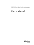
Series 8500 FDMS Monitor consists of three basic components: the 8500 module
(Figure 1-1), TEOM Series 1400a sensor unit (containing the sample inlet and mass
transducer) (Figure 1-2), and the TEOM Series 1400a control unit (containing the
operator terminal and control electronics) (Figure 1-2).
Figure 1-1. Series 8500C
FDMS module.
SECTION 1: INTRODUCTION
PAGE 1-1
Revision C.000
Operating Manual, Series 8500 FDMS™ Filter Dynamics Measurement System
Figure 1-2. TEOM Series
1400a sensor unit (A) and
control unit (B).
A
B
SECTION 1: INTRODUCTION
PAGE 1-2
Revision C.000
Operating Manual, Series 8500 FDMS™ Filter Dynamics Measurement System
The Series 8500 FDMS Monitor can be configured with a variety of sample inlets to
measure PM-10, PM-2.5 or PM-1 concentrations. The microprocessor-based unit
accommodates all siting requirements and provides internal data storage and analog
and serial data input/output capabilities.
The Series 8500 FDMS™ Filter Dynamics Measurement System provides a representative determination of the particulate matter (PM) concentration as it exists in the
ambient air. The FDMS unit automatically generates mass concentration measurements (µg/m3) that account for both nonvolatile and volatile PM components.
The system is composed of a TEOM Series 1400a Ambient Particulate Monitor
loaded with Series FDMS 8500 module operating software and an FDMS kit. For
current users of TEOM Series 1400a (Revision B) monitors, the FDMS kit can be
added to an existing installation (Section 2).
The FDMS system is composed of two major subsystems:
•
The sampling system consists of a size-selective inlet, flow splitter, air
chiller/dryer, and a switching valve that is used to direct the sample flow
through the 8500 module.
•
The analysis and control system is made up of a sample filter that is part
of the TEOM microbalance, humidity sensors for the main and bypass
flows, and a control unit containing flow controllers and data management hardware.
The mass calibration verification kit allows users to confirm FDMS mass measurement accuracy using an NIST-traceable mass transfer standard.
The Streamline FTS Flow Transfer Standard uses differential pressure across a
specially constructed orifice to determine flow rates. The unit is calibrated on a bench
developed in a collaborative effort between the manufacturer, Chinook Engineering
LLC, and NIST (National Institute of Standards and Technology).
Based upon the adjusted change in the filter sample mass and sampled volume, the
FDMS unit computes a one-hour running average of the PM mass concentration. The
instrument updates this value every six minutes based upon the newest information.
The unit calculates the mass concentration (MC) based on the slope of the frequency
(mass) that is measured during each base/reference measurement period (six minutes).
SECTION 1: INTRODUCTION
PAGE 1-3
Revision C.000
Operating Manual, Series 8500 FDMS™ Filter Dynamics Measurement System
Based upon mass concentration (MC) measurements obtained during the base and
reference periods, the FDMS system updates a one-hour average of the following
results every six minutes (Section 7):
•
Base mass concentration (Base MC) = PM concentration of the particleladen sample stream (comparable to the Sample Equilibration System at
30° C).
•
Reference mass concentration (Ref MC) = PM concentration of the
particle-free sample stream, after passing through the purge filter.
•
Mass concentration (MC) = Base mass concentration (Base MC) adjusted by the reference mass concentration (Ref MC) — Base MC
(usually positive) minus Ref MC (negative when mass volatilizes from
the filter).
For example, the unit draws a base flow for six minutes and measures a mass
concentration of “5” (Base MC = 5). Then the unit draws a reference flow for six
minutes and measures a mass concentration of “-1” (Ref MC = -1).
Therefore, the mass concentration is “6,” where:
MC = Base MC - Ref MC
6 = 5 - (-1)
SECTION 1: INTRODUCTION
PAGE 1-4
Revision C.000
Operating Manual, Series 8500 FDMS™ Filter Dynamics Measurement System
1.1.
ADVANCED FEATURES
The Series 8500 FDMS Monitor contains the following features:
SECTION 1: INTRODUCTION
•
Self-referencing real-time TEOM mass monitor
•
Sample Equilibration System (SES) used to dry and condition the sample
stream
•
Active volumetric (ActiVol) flow control incorporating mass flow
controllers, sensors for ambient temperature and pressure, and the
control logic for maintaining a constant volumetric flow rate
•
Characterized size-selective inlet systems operating at 1 m3/h (16.7 l/
min) for PM-10, PM-2.5 and PM-1 sampling
•
TEOM inertial microbalance system providing a consistent, true mass
reading of the collection filter mass
•
Mass transducer design provides improved mass resolution for shortterm measurements
•
Incorporates “AB” technology for enhanced measurement stability for
mobile installations
•
Filter-based, direct mass monitoring using TEOM technology. The instrumentation contains no radioactive components and has a 2-year warranty.
•
Continuous dust monitor with U.S. EPA approval (EQPM-1090-079)
that complies with the California ARB 1-hour acceptance criteria for
mass concentration precision.
•
Mass and time resolution (mass transducer minimum detection limit of
0.06 µg). The instrument has a precision of ±2.5 µg/m³ for 1-hour
averages.
•
Available with a choice of sample inlets for PM-10, PM-2.5, or PM-1
measurements
•
Sample filters can be analyzed after exposure for heavy metals using
standard laboratory techniques such as AA or ICAP.
PAGE 1-5
Revision C.000
Operating Manual, Series 8500 FDMS™ Filter Dynamics Measurement System
SECTION 1: INTRODUCTION
•
Viewing and entry of instrument parameters are made possible by a menudriven user interface. Keypads are available in English, Spanish and
German.
•
Internal data logging of up to 40 weeks with one data record stored every
hour. Each record may contain up to eight user-selectable variables.
•
Two levels of password protection – low and high lock. These can be used
to restrict access to instrument functions.
•
Advanced RS232 support. This allows users to retrieve real-time and
stored information and change instrument parameters, both remotely and
at the sampling location.
•
Three real-time analog outputs allow straightforward connections to data
loggers or chart recorders. These outputs can be configured as 0-1, 0-2,
0-5 or 0-10 VDC. The monitor also contains two user-definable, contact
closure circuits.
PAGE 1-6
Revision C.000
Operating Manual, Series 8500 FDMS™ Filter Dynamics Measurement System
1.2.
OVERVIEW OF MANUAL
This manual describes the installation and operation of the Series 8500 FDMS
Monitor. Follow the setup instructions contained in Sections 2 and 3 before applying
power to the unit in the manner described in Section 5.
This manual is divided into 13 sections and 10 appendices that discuss different topics.
Sections 1 and 2 explain the system hardware, while later sections describe the
system’s software and the setup and operation of the monitor. The following list
provides an overview of the topics handled in each section of the manual:
Section 1: Introduction
This section provides an overview of the Series 8500 FDMS Monitor, as well as the
theory of operation of the instrument’s mass transducer.
Section 2: Hardware Installation
This section describes how to set up the system’s hardware.
Section 3: Sample Preparation
A TEOM and 47 mm filter must be installed in the system before the unit is turned on.
This section explains the steps required to install and exchange these filters.
Section 4: Software Overview
This section describes the operation of the Series 8500 FDMS Monitor, including
viewing system data on the four-line display and changing instrument operating
parameters.
Section 5: Basic Operation
This section provides brief instructions on how to turn on the instrument and initiate
a sampling run. It also explains how to download data and how to perform an audit
of the instrument.
Section 6: Software Setup
This section explains how to set up the instrument’s software to run a sample.
Section 7: Status Codes
This section explains the monitor’s status code information and screens.
Section 8: Viewing Stored Data
This section explains how to view the data stored in the Series 8500 FDMS Monitor.
SECTION 1: INTRODUCTION
PAGE 1-7
Revision C.000
Operating Manual, Series 8500 FDMS™ Filter Dynamics Measurement System
Section 9: Data Input and Output
This section explains how to use the monitor’s two user-definable contact closure
circuits and three analog outputs. This section also explains how to download data
through the RS232 port to a serial printer, personal computer (PC) and other data
capture devices, such as a data logger.
Section 10: Using RPComm
RPComm is a communications software package for Windows operating systems that
provides interactive remote communications with the instrumentation. This section
describes how to set up a Series 8500 FDMS Monitor for direct communications with
a personal computer and how to use RPComm.
Section 11: Password Protection
This section explains how to set and remove the Series 8500 FDMS Monitor’s
password protection.
Section 12: Routine Maintenance and Verification Procedures
This section describes the routine maintenance and verification procedures for the
Series 8500 FDMS Monitor.
Section 13: Resetting The Unit
This section explains how to reset the Series 8500 FDMS Monitor.
Appendix A: Overview of Software Screens
This appendix provides an overview of the screens that appear on the Series 8500
FDMS Monitor, and the RPComm and TEOMCOMM software applications.
Appendix B: Program Register Codes
This appendix lists the code assignments for system variables (program register codes
(PRCs)) used to define the operation of the instrument.
Appendix C: Two-Way Serial Communication
This appendix describes the two-way RS232 protocols used to exchange information
between the Series 8500 FDMS Monitor and a computer or data logger.
Appendix D: Installing New Software
This appendix explains how to install new system software into the Series 8500 FDMS
Monitor. This appendix also explains how to obtain and load RPComm onto your
personal computer (PC).
Appendix E: Consumables and Parts
This appendix lists the consumables and spare parts used in the Series 8500 FDMS
Monitor.
SECTION 1: INTRODUCTION
PAGE 1-8
Revision C.000
Operating Manual, Series 8500 FDMS™ Filter Dynamics Measurement System
Appendix F: Filter Log
This appendix contains a filter log to track all readings associated with each exposed
filter.
Appendix G: Inlet Maintenance
This appendix contains maintenance procedures for the PM-10 inlet, the modified
PM-10 inlet, the sharp cut cyclone (SCC) PM-1 and PM-2.5 inlets.
Appendix H: Modem Communications
This appendix describes how to connect the Series 8500 FDMS Monitor to a modem
for offsite communications and how to set up a serial switching device for use with
multiple instruments.
Appendix I: ASCII Codes
This appendix contains a list of the principal ASCII codes that may be used for setting
up the instrument’s RS232 communications protocol.
Appendix J: TEOMCOMM Software
This appendix describes the screens and operation of the TEOMCOMM software
program.
Appendix K: Outdoor Enclosure
This appendix describes how to install the Series 8500 FDMS Monitor into the
outdoor enclosure.
Appendix L: Series 8500 Schematics
This appendix includes the interconnect diagrams of the Series 8500
SECTION 1: INTRODUCTION
PAGE 1-9
Revision C.000
Operating Manual, Series 8500 FDMS™ Filter Dynamics Measurement System
1.3.
APPLICATION RANGE
The Series 8500 FDMS Monitor is a real-time device used for measuring the
particulate matter mass concentration of particulate matter smaller than 10 µm
diameter in outdoor and indoor ambient air.
TEOM instruments are the only filter-based mass monitors that measure the mass of
particulate matter suspended in gas streams in real time. This is made possible through
the use of an inertial mass transducer patented in the U.S. and internationally by
Thermo Electron Corporation.
The monitor is ideally suited for applications demanding real-time ambient air
particulate matter monitoring in outdoor, indoor or industrial settings. It calculates
mass concentration, mass rate and the total mass accumulation on the TEOM filter
under the following conditions:
Flow rate through sample inlet
Main flow rate
Temperature of sample stream
Particulate matter concentration
16.7 l/min (1 m3/hr)
3 l/min
30º C
less than 5 µg/m3 to several g/m3
The ambient temperature sensor can measure temperatures ranging from -25º to 105º
C, with an accuracy of ±2º C. The ambient pressure sensor is rated from 0.68 to 1.09
atm, and is specified to have a maximum error of 1.5% in the temperature range of 0º
to 85º C. The Series 8500 FDMS Monitor smooths both the average temperature and
average pressure over a period of approximately 15 seconds.
The Series 8500 FDMS Monitor uses the PM-10 inlet to perform a 10 µm particle size
cutoff. Other size-selective inlets are available for PM-2.5 and PM-1 monitoring
(Section 2).
SECTION 1: INTRODUCTION
PAGE 1-10
Revision C.000
Operating Manual, Series 8500 FDMS™ Filter Dynamics Measurement System
1.4.
GENERAL SYSTEM CONFIGURATION
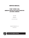
The Series 8500 FDMS Monitor is composed of three major components (Figure 14): the TEOM Series 1400a sensor unit, TEOM Series 1400a control unit, and the 8500
module. The user enters the system parameters into the control unit with the keypad,
that is located on the front of the unit. Additionally, the system is furnished with
software for personal computers to allow the user to view the operation of the
instrument in real time, and to allow the user to enter system values directly from the
PC. The instrument does not require a dedicated computer to function in the field.
Figure 1-4. Schematic
diagram of a typical
installation.
Sample inlet
8500 module
Control
unit
SECTION 1: INTRODUCTION
Sensor unit
PAGE 1-11
Revision C.000
Operating Manual, Series 8500 FDMS™ Filter Dynamics Measurement System
The sensor unit contains the mass measurement hardware that continuously monitors
the accumulated mass on the system’s exchangeable TEOM filter. By maintaining a
flow rate of 3 l/min through the instrument and measuring the total mass accumulated
on the TEOM filter, the device can calculate the mass concentration of the sample
stream in near real-time.
The control unit houses an industrially hardened microprocessor system, flow control
hardware, a gauge to determine filter lifetime, transformers and power supplies.
SECTION 1: INTRODUCTION
PAGE 1-12
Revision C.000
Operating Manual, Series 8500 FDMS™ Filter Dynamics Measurement System
1.5.
THEORY OF OPERATION
The Series 8500 FDMS Monitor is a true “gravimetric” instrument that draws ambient
air through a filter at a constant flow rate, continuously weighing the filter and
calculating near real-time mass concentrations. In addition, the instrument computes
the 1-hour, 8-hour, 12-hour and 24-hour averages of the mass concentration. Both
analog and RS232 outputs are available to transmit the measurements to a user’s data
acquisition system. The instrument’s internal storage buffer can store a large amount
of data for later viewing on the instrument’s display or downloading over the RS232
output.
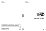
There are five air stream flows in the FDMS Series 8500 Monitor: the main flow, base
flow, reference flow, bypass flow, and the purge flow (Figure 1-5).
SECTION 1: INTRODUCTION
PAGE 1-13
Revision C.000
Operating Manual, Series 8500 FDMS™ Filter Dynamics Measurement System
Figure 1-5. Flow diagram of
a typical installation.
Sample
inlet
Bypass
flow
Main
flow
8500
module
Bypass
flow
Purge
flow
To pump
Base/
reference
flow
Bypass
flow
Purge
flow
Control
unit
SECTION 1: INTRODUCTION
Base/
reference
flow
Sensor
unit
PAGE 1-14
Revision C.000
Operating Manual, Series 8500 FDMS™ Filter Dynamics Measurement System
Main Flow
After passing through a PM-10, PM-2.5 or PM-1 size-selective sample inlet (Figure
1-5), the sample stream is split isokinetically into a main flow of 3 l/min that is used
for the automated PM measurement and a bypass flow of 13.7 l/min. The main flow
enters the 8500 module (Figure 1-5) where it becomes the base flow (Figure 1-6) or
the reference flow (Figure 1-7), depending on the valve position inside the 8500
module.
Base Flow
Inside the 8500 module, the base flow (Figure 1-6) is dried in an SES diffusion dryer
that minimizes relative humidity effects upon PM measurements. The base flow then
enters the TEOM Series 1400a sensor unit (Figure 1-5). In the sensor unit, the base
flow passes through an exchangeable collection filter that is mounted on a TEOM
microbalance. This mass transducer continuously provides a direct measurement of
the PM mass collected on the filter. After the base flow passes through the TEOM
filter, it enters the TEOM Series 1400a control unit where an electronics system
transmits the appropriate set points to the main mass flow controller to maintain
constant volumetric flow rates. This active volumetric control (ActiVolTM) system is
based upon inputs from ambient temperature and pressure sensors. When the base
flow exits the TEOM Series 1400a control unit it becomes the purge flow.
SECTION 1: INTRODUCTION
PAGE 1-15
Revision B.002
Operating Manual, Series 8500 FDMS™ Filter Dynamics Measurement System
Figure 1-6. Base flow
diagram inside the 8500
module.
Main flow from
sample inlet
SES dryer
Switching
valve
47 mm
filter
PURGE
INLET
Purge flow
from
control unit
PURGE
OUTLET
Purge flow to
pump
Base flow to
TEOM filter
SECTION 1: INTRODUCTION
PAGE 1-16
Revision C.000
Operating Manual, Series 8500 FDMS™ Filter Dynamics Measurement System
Reference Flow
Inside the 8500 module, the base flow is dried in an SES diffusion dryer that minimizes
relative humidity effects upon PM measurements. A switching valve positioned after
the SES dryer changes the flow path of the base/reference flow every six minutes. The
sampling process consists of alternate base and reference cycles. During the reference
cycle, the air flow passes through a 47 mm filter where it becomes the reference flow
(Figure 1-7). The 47 mm filter in the 8500 module produces a sample air stream
without particulate matter. The 47 mm filter is maintained at 4° C to provide a timeintegrated sample that can be used for subsequent chemical analysis. The 8500
module contains a standard FRM-style molded filter cassette which contains a 47 mm
diameter, TX40 material filter. The reference flow then enters the TEOM Series 1400a
sensor unit (Figure 1-5). In the sensor unit, the reference flow passes through an
exchangeable collection filter that is mounted on a TEOM microbalance. This mass
transducer continuously provides a direct measurement of the PM mass collected on
the filter. After the reference flow passes through the TEOM filter, it enters the TEOM
Series 1400a control unit where an electronics system transmits the appropriate set
points to the main mass flow controller to maintain constant volumetric flow rates. This
active volumetric control (ActiVolTM) system is based upon inputs from ambient
temperature and pressure sensors. When the reference flow exits the TEOM Series
1400a control unit it becomes the purge flow.
SECTION 1: INTRODUCTION
PAGE 1-17
Revision B.002
Operating Manual, Series 8500 FDMS™ Filter Dynamics Measurement System
Figure 1-7. Reference flow
diagram inside the 8500
module.
Main flow from
sample inlet
SES dryer
Switching
valve
47 mm
filter
PURGE
INLET
Purge flow
from
control unit
SECTION 1: INTRODUCTION
PURGE
OUTLET
Purge flow to
pump
Reference flow to
TEOM filter
PAGE 1-18
Revision C.000
Operating Manual, Series 8500 FDMS™ Filter Dynamics Measurement System
Purge Flow
When the base/reference flow leaves the control unit it travels back to the 8500
module to become the purge flow (Figures 1-5, 1-6 and 1-7). Inside the 8500 module,
the purge flow enters the SES dryers where it flows around the base/reference flow
to dry the ambient air sample entering the system. This system achieves an effective
drying of the base/reference flow to less than 30% relative humidity without requiring
any bottled gases or specialized electrical components. The purge flow then enters the
pump, and exits from the 8500 system.
The mass reading obtained while sampling particle-laden air is adjusted for any mass
change that occurs while the reference flow passes through the filter. For example, if
the unit measures a decrease of filter mass during the six-minute reference flow
period, this mass decrease is added back to the mass measurement obtained with
particle-laden air (base flow). In this manner, the FDMS system compensates for the
volatilization effects that can occur in filter-based PM continuous monitors or
integrated samplers.
All measurement and temperature functions of the instrument are controlled by a
dedicated microcontroller. This computer has both digital and analog capability for
multipurpose interfacing with external data collection systems.
Bypass Flow
After passing through a PM-10, PM-2.5 or PM-1 size-selective sample inlet (Figure
1-5), the sample stream is split isokinetically into a main flow of 3 l/min that is used
for the automated PM measurement and a bypass flow of 13.7 l/min (Figures 1-5, 16 and 1-7). The bypass flow enters the TEOM Series 1400a control unit where an
electronics system transmits the appropriate set points to the bypass mass flow
controller to maintain constant volumetric flow rates. This active volumetric control
(ActiVolTM) system is based upon inputs from ambient temperature and pressure
sensors. When the bypass flow exits the TEOM Series 1400a control unit it then enters
the pump, and exits from the 8500 system.
SECTION 1: INTRODUCTION
PAGE 1-19
Revision C.000
Operating Manual, Series 8500 FDMS™ Filter Dynamics Measurement System
1.6.
MASS TRANSDUCER OPERATION
The weighing principle used in the TEOM mass transducer (Figure 1-8) is similar to
that of a laboratory microbalance in that the mass detected by the sensor is the result
of the measurement of a change in a parameter (in this case, frequency) that is directly
coupled via a physical law (or from first principles).
Figure 1-8. Schematic
diagram of mass transducer.
SECTION 1: INTRODUCTION
PAGE 1-20
Revision C.000
Operating Manual, Series 8500 FDMS™ Filter Dynamics Measurement System
The tapered element at the heart of the mass detection system is a hollow tube, clamped
on one end and free to oscillate at the other. An exchangeable TEOM filter cartridge
is placed over the tip of the free end. The sample stream is drawn through this filter,
and then down the tapered element. This flow is maintained at a constant volume by
a mass flow controller that is corrected for local temperature and barometric pressure.
The tapered element oscillates precisely at its natural frequency, much like the tine
of a tuning fork. An electronic control circuit senses this oscillation and, through
positive feedback, adds sufficient energy to the system to overcome losses. An
automatic gain control circuit maintains the oscillation at a constant amplitude. A
precision electronic counter measures the oscillation frequency with a 2-second
sampling period.
The tapered element is, in essence, a hollow cantilever beam with an associated spring
rate and mass. As in any spring-mass system, if additional mass is added, the
frequency of the oscillation decreases. This can be seen by observing the frequency
on the four-line display of the TEOM control unit (Section 4), and operating the Series
8500 FDMS Monitor both with and without a filter in place.
In a spring-mass system the frequency follows the equation:
f = (K / M)0.5
(1)
where:
f =
K =
M =
frequency (radians/sec)
spring rate
mass
K and M are in consistent units. The relationship between mass and change in
frequency can be expressed as:
dm = K0
1
1
–––––– - ––––––
f1 2
f 02
(2)
where:
dm
K0
f0
f1
SECTION 1: INTRODUCTION
=
=
=
=
change in mass
spring constant (including mass conversions)
initial frequency (Hz)
final frequency (Hz)
PAGE 1-21
Revision C.000
Operating Manual, Series 8500 FDMS™ Filter Dynamics Measurement System
When this equation is rearranged, you can solve for the spring constant, K0:
K0 =
✔ Each TEOM instrument
has a unique calibration
constant, K0.
SECTION 1: INTRODUCTION
dm
–––––––––––––––
1
1
–––––– - ––––––
f 12
f 02
(3)
Thus, K0 (the calibration constant for the instrument) can be easily determined by
measuring the frequencies with and without a known mass (pre-weighed TEOM filter
cartridge).
PAGE 1-22
Revision C.000
Operating Manual, Series 8500 FDMS™ Filter Dynamics Measurement System
1.7.
MASS FLOW CONTROLLERS
The mass flow controllers (MFCs) in the Series 8500 FDMS Monitor are internally
calibrated for a standard temperature and pressure of 0° C and 1 Atmosphere (1013.2
millibars or 760 mm Hg). The user must enter the seasonal average temperature (Ave.
Temp.) and average barometric pressure (Ave. Pres.) at the measurement site to allow
the instrument to sample at the correct volumetric flow rate (Section 6).
Alternately, the user can set up the instrument to automatically measure the ambient
temperature and pressure using hardware supplied with the unit. The microprocessor
calculates the correct mass flow set point (Flow_RateSTP) with this information using
the following formula:
273.15
Ave. Pres.
Flow_RateSTP = Flow_RateVol × –––––––––––––––– ×
––––––––– (4)
Ave. Temp. + 273.15
1.0
where:
Flow_RateSTP
=
Control setpoint to mass flow controller (equivalent flow at
0° C and 1 Atmosphere)
Flow_RateVol
=
Volumetric flow rate setpoint (l/min) to be 3.0 l/min for the
sample (main) flow and 13.67 l/min for the auxiliary flow
(Section 6)
Ave. Temp.
=
Seasonal average temperature entered by the user (°C)
Ave. Pres.
=
Seasonal average barometric pressure entered by the user
(Atmospheres, where 1 Atmosphere = 1013.2 millibars or
760 mm Hg)
NOTE: When using actual conditions for active volumetric
flow control, substitute the actual (local) temperature and
pressure for the average temperature and pressure variables
in equation 4.
PM-10 mass concentration data reported to the U.S. EPA must be referenced to
standard cubic meters of air based on a standard temperature and pressure of 25° C
and 1 Atmosphere (atm), respectively. For the instrument to report mass concentrations according to this EPA standard, the user must ensure that the standard
temperature (Std. Temp.) and standard pressure (Std. Pres.) entered in the instrument
equal 25° C and 1 Atmosphere (Section 6). These are the default values for the
instrument.
SECTION 1: INTRODUCTION
PAGE 1-23
Revision C.000
Operating Manual, Series 8500 FDMS™ Filter Dynamics Measurement System
The flow rates referenced internally by the instrument to 0° C are converted to EPA
standard conditions using the following computation:
Std. Temp. + 273.15
Flow_RateEPA = Flow_RateSTP × –––––––––––––––––
273.15
1 atm
× ––––––––
Std. Pres.
(5)
NOTE: When reporting concentrations to actual conditions,
the values for standard and average temperatures must be set
to “99,” and the standard and average pressures must be set
to “9,” when in the Set Temps/Flows screen (Section 6). This
will ensure that the monitor uses the current actual values for
temperature and pressure in equation 5.
SECTION 1: INTRODUCTION
PAGE 1-24
Revision C.000
Operating Manual, Series 8500 FDMS™ Filter Dynamics Measurement System
1.8.
OPERATING CONDITIONS
In some operating conditions, the Series 8500 FDMS Monitor may require additional
steps to reduce the chance of condensation inside the system.
Do not operate the Series 8500 FDMS Monitor without a taking precautions to reduce
condensation if the external dew point temperature (outside, at the inlet) exceeds the
ambient temperature that the control and sensor unit will be operated in (indoors or
in an enclosure). The control unit may be located in any convenient indoor location
which is maintained between 2° and 25° C (35° to 77° F). For example, if the dew point
at the inlet is 24° C (75° F), and the indoor temperature of your facility is 20° C (68°
F), you must take additional steps to prevent condensation. However is your site is 25°
C (77° F) and the dew point is 23° C (73° F), you can safely operate the monitor.
If you have purchased the Series 8500 FDMS Monitor Module as an add-on kit to an
already existing TEOM 1400a system, your existing 1400a control unit must have the
second generation flow controllers (Section 2.1). If you purchased your Series 1400a
Monitor before February 2001, or if the serial number on your monitor is
140AB234170011 or below, your control unit may have the original design mass flow
controllers. Refer to Section 2.1 for additional information on determining if you have
the original design mass flow controllers and how to replace them.
SECTION 1: INTRODUCTION
PAGE 1-25
Revision C.000
Operating Manual, Series 8500 FDMS™ Filter Dynamics Measurement System
This page left intentionally blank.
SECTION 1: INTRODUCTION
PAGE 1-26
Revision C.000
Operating Manual, Series 8500 FDMS™ Filter Dynamics Measurement System
Section 2: Hardware Installation
To install the Series 8500 FDMS Monitor and set up the system, you must check the
voltage setting of the control unit (Section 2.4.1); assemble the main flow connections
(Section 2.4.3.1), the bypass flow connections of the control unit (Section 2.4.3.2), the
8500 module (Section 2.4.4), the electrical connections (Section 2.4.5), the sensor
unit connections (Section 2.4.6), the flow splitter (Section 2.5.1), the tripod (Section
2.5.2), the sample tube (Section 2.5.3), and the sampling system components (Section
2.5.4); and install a sample inlet onto the flow splitter (Section 2.5.5). After you have
set up the system, you must perform a leak check on the monitor (Section 3) and install
a filter in the mass transducer and the 8500 filter conditioner unit (Section 3) before
starting a sample run.
2.1.
✔ The instrument must be
located in a weatherprotected environment.
✘ Be sure to install the
ambient temperature
sensor.
INSTALLATION CONSIDERATIONS
The Series 8500 FDMS Monitor consists of three basic components: the TEOM Series
1400a sensor unit (containing the sample inlet and mass transducer), TEOM Series
1400a control unit (containing the operator terminal and control electronics), and the
8500 module. If you have purchased the Series 8500 FDMS Monitor as a total
package, including the Series 1400a control and sensor units and 8500 module, follow
all instructions in this section with the exception of Section 2.3 (Converting a 1400
Control Unit). If you have purchased the 8500 module as an add-on kit, you must
follow the instructions in these subsections only: Section 2.3. (Converting a 1400
Control Unit), Section 2.4.2 (8500 Module Brace), Section 2.4.3 (Control Unit
Connections), Section 2.4.4 (8500 Module Installation), Section 2.4.5 (Electrical
Connections), Section 2.5.3 (Sample Tube Assembly), and Section 2.5.4 (Sampling
System Setup, steps 15-20 only).
IMPORTANT: If you are running your TEOM Series
1400a System with a flow adapter installed inside the flow
splitter, you MUST REMOVE the flow adapter from the
inside of the flow splitter.
The control unit may be located in any convenient indoor location which is maintained
between 2° and 25° C (35° to 77° F).
Thermo strongly recommends that the sensor unit also be installed in an indoor or
weather-protected location. If the sensor unit is installed in an indoor location, the user
must run a sampling tube through the roof of the monitoring site.
Although the monitor is inherently rugged, it is a precision instrument. The user will
obtain the best operating conditions and longest instrument life when the unit is not
exposed to extremes of weather. Filter exchange, in particular, may be best accomplished by a technician operating in an indoor environment where there is no
possibility of rain or snow contaminating the filter.
SECTION 2: HARDWARE INSTALLATION
PAGE 2-1
Revision C.000
Operating Manual, Series 8500 FDMS™ Filter Dynamics Measurement System
✔ The sample tubing must
be vertical.
Be sure to install the ambient temperature sensor. If you do not install the ambient
temperature sensor, and set the average temperature to “99” and the average pressure
to “9” (Section 5), the mass flow controller will attempt to control the sample flow as
if the ambient temperature is absolute zero.
The sample line should proceed in a straight, vertical line from the sample inlet
(Section 2.5.5) to the inlet of the sensor unit through a 4 cm (1 1/2") diameter hole in
the roof of the monitoring site.
To achieve the best results, locate the sensor unit in an environment with relatively
slow temperature fluctuations. Avoid sampling locations with direct exposure to
sunlight or that are in close proximity to a heating or air-conditioning outlet. To avoid
condensation in the sample tubing, Thermo strongly recommends that the user
insulate the sample tube extensions with pipe insulation when operating the
instrument in areas of high humidity.
If you have purchased the Series 8500 FDMS Module as an add-on kit to an already
existing TEOM Series 1400a System, you must add the new dual-flow fitting (Section
2.3.1) and load the new system software that came with the 8500 module into your
Series 1400a control unit (Appendix D). This will convert your TEOM Series 1400a
System into a Series 8500 FDMS Monitor.
IMPORTANT: If you have purchased the Series 8500
FDMS Module as an add-on kit to an already existing TEOM
1400a System, your existing 1400a system must have the
second generation flow controllers (Figure 2-1) installed
inside the control unit. If you purchased your Series 1400a
System before February 2001, or if the serial number on your
monitor is 140AB234170011 or below, your control unit
may have the original design mass flow controllers (Figure
2-2). If your flow controllers make a “clicking” sound, you
have the original design flow controllers. If you have (or
think you have) the original design flow controllers, contact
R&P for information on obtaining a Second Generation
Mass Flow Controllers replacement kit, and refer to Section
2.3.2 for instructions on replacing the original design flow
controllers.
SECTION 2: HARDWARE INSTALLATION
PAGE 2-2
Revision C.000
Operating Manual, Series 8500 FDMS™ Filter Dynamics Measurement System
Figure 2-1. Second
generation flow controllers.
Figure 2-2. Original design
flow controllers.
SECTION 2: HARDWARE INSTALLATION
PAGE 2-3
Revision C.000
Operating Manual, Series 8500 FDMS™ Filter Dynamics Measurement System
2.2.
STANDARD SYSTEM HARDWARE
In its most basic PM-10 configuration, the Series 8500 FDMS Monitor is supplied
with the following components:
TEOM Series 1400a control unit (with auxiliary flow controller)
TEOM Series 1400a sensor unit
8500 module
8500 module brace stand and base
8500 FDMS software package
3 10/32-inch x 5/8-inch screws
Vacuum pump
Water condensation trap kit
Temperature sensor and cable, 10 m
Electric- and air-connecting cable
2 2-foot red/black wire lengths, round connector to 15-pin connector
5 m (16.5 ft) 3/8-inch nylon green tubing
3 ft 1/4-inch black tubing
3-inch insulation sleeve
2 sample tube extensions, 1 m (40-inch)
9-to-9 pin RS232 serial pin cable
9-to-15 pin valve signal cable
15-to-15 pin valve position cable
15-to-25 pin data interface cable
9-to-25 pin computer adapter
9-to-25 pin modem cable
Data interface cable, 15-pin to 25-pin
Module connection cable
3 power cables
Box of 20 TEOM filter cartridges
Box of 25 filter cartridges (47 mm Pallflex TX40)
2 filter cassettes
4 large in-line filters
Filter exchange tool
Pre-filter assembly (for baseline testing)
Flow audit filter
Flow splitter
PM-10 inlet
Flow audit adapter kit
Valve cleaning brush
2 15-pin subminiature D-connectors
2 18 mm hex nuts
4 hose barbs
SECTION 2: HARDWARE INSTALLATION
PAGE 2-4
Revision C.000
Operating Manual, Series 8500 FDMS™ Filter Dynamics Measurement System
Metal 3/8-inch to 1/4-inch reducer fitting
1/2-inch x 1/2-inch push-to-connect union fitting
3/8-inch x 3/8-inch push-to-connect union fitting
3/8-inch x 3/8-inch push-to-connect elbow fitting
2 3.15 Amp fuses
2 FDMS Series 8500 Operating Manuals (1 binder, 1 on CD-ROM)
2 TEOM Series 1400a Service Manuals (1 binder, 1 on CD-ROM)
SECTION 2: HARDWARE INSTALLATION
PAGE 2-5
Revision C.000
Operating Manual, Series 8500 FDMS™ Filter Dynamics Measurement System
2.3.
CONVERTING A 1400 CONTROL UNIT
If you have purchased the Series 8500 FDMS Module as an add-on kit to an already
existing TEOM 1400a System, you must install the dual-flow fitting into the Series
1400a control unit (Section 2.3.1). Also, your Series 1400a control unit must have the
second generation flow controllers (Section 2.3.2). Refer to Section 2.1 for assistance
in determining if you have the second generation flow controllers.
NOTE: If you have to install both the dual-flow fitting and
the second generation flow controllers, be sure to install the
dual-flow fitting first, before installing the second generation flow controllers.
SECTION 2: HARDWARE INSTALLATION
PAGE 2-6
Revision C.000
Operating Manual, Series 8500 FDMS™ Filter Dynamics Measurement System
2.3.1.
INSTALLING THE DUAL-FLOW FITTING
If you have purchased the Series 8500 FDMS Module as an add-on kit to an already
existing TEOM Series 1400a System, you must convert the flow configuration inside
the control unit and modify the pump port on the back of the control unit.
Tools and materials needed for this procedure:
Dual-flow fitting
2 plastic 3/8-inch to 1/4-inch reducer fittings
Adjustable wrench
Follow these steps to install the dual-flow fitting:
1) Remove the top cover of the control unit.
2) Locate the mass flow controller assembly inside the control unit
(Figure 2-3) in the back, right-hand corner.
Figure 2-3. Interior view of
the control unit.
BACK
Mass flow controller
assembly
FRONT
SECTION 2: HARDWARE INSTALLATION
PAGE 2-7
Revision C.000
Operating Manual, Series 8500 FDMS™ Filter Dynamics Measurement System
3) Locate the hoses and Y-fitting connected to the mass flow controller assembly (Figure 2-4).
Figure 2-4. Mass flow
controller assembly with Yfitting and hoses
highlighted.
Y-fitting
Mass flow controller
assembly
Bypass flow hose
Main flow hose
SECTION 2: HARDWARE INSTALLATION
PAGE 2-8
Revision C.000
Operating Manual, Series 8500 FDMS™ Filter Dynamics Measurement System
4) Locate the PUMP port on the back (Figure 2-5) and inside (Figure
2-6) of the control unit.
Figure 2-5. Back of the
sensor unit with “PUMP”
port highlighted.
PUMP port
Figure 2-6. Interior of the
control unit with “PUMP”
port, small metal collar and
Y-fitting highlighted.
PUMP port
Small metal
collar
Y-fitting
SECTION 2: HARDWARE INSTALLATION
PAGE 2-9
Revision C.000
Operating Manual, Series 8500 FDMS™ Filter Dynamics Measurement System
5) Disconnect the main flow hose and bypass flow hose from the Yfitting by pushing in on the small collars at the end of the Y-fitting
and pulling the hoses out (Figure 2-7).
Figure 2-7. Removing a
hose from the Y-fitting.
Small collars
Hoses
NOTE: Do not remove the rigid hose adapters that are installed inside the ends
of the main flow hose and the bypass flow hose (Figure 2-8).
Figure 2-8. Rigid hose
adapter installed inside the
end of a hose.
Rigid hose
adapter
SECTION 2: HARDWARE INSTALLATION
PAGE 2-10
Revision C.000
Operating Manual, Series 8500 FDMS™ Filter Dynamics Measurement System
6) Disconnect the Y-fitting from the pump fitting by pushing on the
small metal collar at the end of the pump fitting and pulling the Yfitting out (Figure 2-9).
Figure 2-9. Removing the
Y-fitting from the pump
fitting.
7) Remove pump fitting from the back of the control unit using the
adjustable wrench (Figure 2-10).
Figure 2-10. Back view of
the control unit with pump
fitting highlighted.
PUMP fitting
SECTION 2: HARDWARE INSTALLATION
PAGE 2-11
Revision C.000
Operating Manual, Series 8500 FDMS™ Filter Dynamics Measurement System
8) Locate the dual-flow fitting (Figures 2-11 and 2-12).
Figure 2-11. Dual-flow
fitting.
Figure 2-12. Close-up view
of the dual-flow fitting with
the dimple highlighted.
Dimple
SECTION 2: HARDWARE INSTALLATION
PAGE 2-12
Revision C.000
Operating Manual, Series 8500 FDMS™ Filter Dynamics Measurement System
9) Install the dual-flow fitting through the empty “PUMP” port (Figure 2-13). When looking at the back of the control unit, ensure
that the “dimple” marking the reference/base (purge) flow side is
located on the right-hand side (Figure 2-14).
Figure 2-13. Dual-flow
fitting installed inside the
control unit.
Figure 2-14. Dual-flow
fitting installed in the control
unit with the dimple highlighted.
Dimple
SECTION 2: HARDWARE INSTALLATION
PAGE 2-13
Revision C.000
Operating Manual, Series 8500 FDMS™ Filter Dynamics Measurement System
10) Install the dual-flow fitting nut onto the dual-flow fitting (this dualflow fitting nut should be attached to the dual-flow fitting when
you receive it in the installation kit) (Figure 2-15).
Figure 2-15. Dual-flow
fitting nut installed on dual
flow fitting.
Dual-flow
fitting nut
11) Locate the main flow metal tube (long tube, dimpled side) and the
bypass flow metal tube (short tube) on the dual-flow fitting (Figure 2-16).
Figure 2-16. Drawing of
dual-flow fitting.
Reducer
fittings
Bypass flow
tube (short)
Dimple
Main flow tube
(long)
SECTION 2: HARDWARE INSTALLATION
PAGE 2-14
Revision C.000
Operating Manual, Series 8500 FDMS™ Filter Dynamics Measurement System
12) Locate the two plastic 3/8-inch to 1/4-inch reducer fittings.
13) Install one plastic 3/8-inch to 1/4-inch reducer fitting on the main
flow metal tube (long tube, dimpled side) of the dual-flow fitting
(Figures 2-16 and 2-17).
NOTE: The Series 8500 FDMS Monitor uses push-to-connect fittings for all air
lines. To engage these connections, the air tube must be pushed completely into
the fitting so that the tube is fully inserted and cannot be pulled out. While
pushing the tubing into the fitting, there is an intermediate stop at an O-ring. You
must push the tubing past the O-ring to completely engage the tubing inside the
fitting and prevent air leaks. To disengage the connection, push the small collar
(located at the end of the fitting) (Figure 2-16) toward the fitting and pull the tube
out.
Figure 2-17. Dual-flow
fitting with the reducer fitting
installed on the main flow
metal tube.
Small collar
SECTION 2: HARDWARE INSTALLATION
PAGE 2-15
Revision C.000
Operating Manual, Series 8500 FDMS™ Filter Dynamics Measurement System
14) Slightly bend the main flow metal tube away from the main flow
controller assembly, enough to allow you to install the other
plastic reducer fitting onto the bypass flow metal tube.
15) Install the other plastic 3/8-inch to 1/4-inch reducer fitting onto the
bypass flow metal tube (short tube) of the dual-flow fitting (Figures 2-16 and 2-18).
Figure 2-18. Dual-flow
fitting with reducer fittings
installed on the main flow
metal tube and bypass flow
metal tube.
Bypass flow
metal tube (short)
Main flow
metal tube (long)
SECTION 2: HARDWARE INSTALLATION
PAGE 2-16
Revision C.000
Operating Manual, Series 8500 FDMS™ Filter Dynamics Measurement System
16) Install the main flow hose (from the main flow side of the flow
controller) into the 3/8-inch to 1/4-inch reducer fitting on the main
flow metal tube (Figure 2-19).
17) Install the bypass flow hose (from the bypass flow side of the flow
controller) into the 3/8-inch to 1/4-inch reducer fitting on the
bypass flow metal tube of the dual-flow fitting (Figure 2-19).
Figure 2-19. Dual-flow
fitting with main flow and
bypass flow hoses installed.
Bypass flow hose
Main flow hose
18) If you must install the second generation flow controllers, go to
Section 2.3.2 (Mass Flow Controller Upgrade). If your 1400a
System already has the second generation flow controllers
installed inside the control unit, go to step 19.
19) Install the top cover onto the control unit, and go to Section 2.4
(Installing the Control and Sensor Units).
SECTION 2: HARDWARE INSTALLATION
PAGE 2-17
Revision C.000
Operating Manual, Series 8500 FDMS™ Filter Dynamics Measurement System
2.3.2.
MASS FLOW CONTROLLER UPGRADE
The replacement procedure includes removing the original design mass flow controllers (Section 2.3.2.1), splicing into the control unit’s 15-volt power supply (Section
2.3.2.2), installing the new mass flow controllers (Section 2.3.2.3) and testing the new
mass flow controllers.
The Mass Flow Controllers Upgrade Kit (Figure 2-20) for the Series 1400a Ambient
Particulate Monitor includes:
Assembled, pre-calibrated mass flow controllers with Technocraft valves
Power wire connector for the new controller (attached)
Wiring harness (attached)
Two splice connectors
Figure 2-20. 1400a flow
controllers with the
Technocraft valves.
Power wire connector
Splice connectors
Wiring harness
SECTION 2: HARDWARE INSTALLATION
PAGE 2-18
Revision C.000
Operating Manual, Series 8500 FDMS™ Filter Dynamics Measurement System
2.3.2.1.
REMOVING THE ORIGINAL MASS FLOW CONTROLLER
Follow these steps to remove the original mass flow controllers:
1) Turn off and unplug the control unit.
2) Remove the top panel from the control unit.
3) Locate the original flow controllers at the right-hand rear corner of
the unit (Figures 2-21 and 2-22).
Figure 2-21. Original flow
controllers.
Figure 2-22. Interior
diagram of the 1400a
control unit with interface
board, flow controller and
15V power supply highlighted.
Interface board
Flow controller
15V power supply
SECTION 2: HARDWARE INSTALLATION
PAGE 2-19
Revision C.000
Operating Manual, Series 8500 FDMS™ Filter Dynamics Measurement System
4) Remove the retaining clip and disconnect the bottom wiring
harness from the interface board (Figure 2-23). Retaining clips
are pieces of thin flexible metal used to secure the cable connectors to the electronics boards (Figure 2-24).
Figure 2-23. 1400a interior
with bottom wiring harness
on interface board highlighted.
Bottom wiring
harness
Flow controller
Figure 2-24. Wiring
harness connection with
retaining clip highlighted.
Retaining clip
SECTION 2: HARDWARE INSTALLATION
PAGE 2-20
Revision C.000
Operating Manual, Series 8500 FDMS™ Filter Dynamics Measurement System
5) Disconnect the tubing and elbow fittings from the SENSOR FLOW
and BYPASS FLOW ports on the back of the control unit (Figure
2-25).
Figure 2-25. Disconnecting
bypass and sensor flow
elbows.
6) Disconnect the tube that extends from the side of the mass flow
controllers to the pump fitting at the inside back panel (Figure 226). Be sure to disconnect the tube at the pump fitting located on
the inside back panel.
Figure 2-26. Original flow
controller with pump tube
and fitting highlighted.
Pump fitting
Pump tube
SECTION 2: HARDWARE INSTALLATION
PAGE 2-21
Revision C.000
Operating Manual, Series 8500 FDMS™ Filter Dynamics Measurement System
7) Disconnect the pressure transducer hose from the mass flow
controllers (Figure 2-27).
Figure 2-27. Original mass
flow controllers with
pressure transducer and
pressure transducer hose
highlighted.
Pressure transducer
Pressure transducer hose
8) Unscrew the two screws that hold the original mass flow controllers to the bottom of the unit (Figure 2-28).
9) Slide the original mass flow controllers back slightly and lift them
out of the unit.
NOTE: Save the two screws to install the new mass flow controllers assembly
(Section 2.3.2.3).
Figure 2-28. Removing the
flow controller screws.
SECTION 2: HARDWARE INSTALLATION
PAGE 2-22
Revision C.000
Operating Manual, Series 8500 FDMS™ Filter Dynamics Measurement System
2.3.2.2.
SPLICING INTO THE POWER SUPPLY
Before installing the new mass flow controllers, you must splice the new valve power
connections wire into the 15-volt power supply located in the front, right-hand corner
of the unit. Use the supplied splice connectors to splice the attached valve power wire
into the power controller mounted in the front, right-hand section of the control unit.
Follow these steps to splice into the power supply:
1) Turn off and unplug the control unit.
2) Locate the power (red) and common (black) wires where they
connect to the 15-volt power supply (Figures 2-22 and 2-29).
Figure 2-29. 15V power
supply with red and black
wires highlighted.
Black wire common
Red wire Power
3) Remove the power wire connectors from the new mass flow
controllers assembly (Figure 2-30).
Figure 2-30. New mass
flow controllers assembly
with power wire connectors
highlighted.
SECTION 2: HARDWARE INSTALLATION
Power wire connectors
PAGE 2-23
Revision C.000
Operating Manual, Series 8500 FDMS™ Filter Dynamics Measurement System
4) Use the two quick splice connectors (Figure 2-31) to attach the
red wire on the new power wire to the red wire on the power
supply and the black power wire on the new power wire to the
black wire on the power supply (Figure 2-32).
Figure 2-31. Splice
connector.
Figure 2-32. Splice
connectors connecting new
flow controller power wires
and 15V power supply.
Flow controllers
black power wire
Power supplyblack wire
Flow controllers
red power wire
SECTION 2: HARDWARE INSTALLATION
Power supplyred wire
PAGE 2-24
Revision C.000
Operating Manual, Series 8500 FDMS™ Filter Dynamics Measurement System
2.3.2.3.
INSTALLING THE NEW MASS FLOW CONTROLLERS ASSEMBLY
Follow these steps to install the new mass flow controllers assembly:
1) Disconnect the sensor and bypass elbow connections from the
new mass flow controllers assembly (Figure 2-33). Use two
wrenches to disconnect the elbow connections. Hold the fittings
that are attached to the mass flow controllers assembly steady
while loosening the elbow connections. If the fittings that are
attached to the mass flow controllers assembly twist while you
are disconnecting the elbow connections, the internal O-rings
will require 24 hours to completely reseal.
Figure 2-33. New mass
flow controllers assembly
with elbows highlighted.
Elbow
connections
SECTION 2: HARDWARE INSTALLATION
PAGE 2-25
Revision C.000
Operating Manual, Series 8500 FDMS™ Filter Dynamics Measurement System
2) Insert the two screws from the original mass flow controllers
assembly into the slots of the new mass flow controllers assembly (Figures 2-34 and 2-35).
Figure 2-34. Placing screw
in flow controller before
installation into the control
unit.
Figure 2-35. New mass
flow controllers assembly
with screw inserted into one
of the slots prior to installation into the control unit.
SECTION 2: HARDWARE INSTALLATION
PAGE 2-26
Revision C.000
Operating Manual, Series 8500 FDMS™ Filter Dynamics Measurement System
3) Slide the unit into the case (Figure 2-36), ensuring that the main
and bypass connections line up with the holes in the back of the
control unit.
Figure 2-36. Sliding the
new mass flow controllers
assembly into the control
unit.
4) Tighten the two screws that hold the mass flow controllers assembly to the bottom of the control unit (Figures 2-37, 2-38 and
2-39).
Figure 2-37 (left). New
mass flow controllers
assembly installed in control
unit with screw in slot.
Figure 2-38 (right). Tightening the screw.
SECTION 2: HARDWARE INSTALLATION
PAGE 2-27
Revision C.000
Operating Manual, Series 8500 FDMS™ Filter Dynamics Measurement System
Figure 2-39. New mass
flow controllers assembly
installed in control unit with
bypass flow, sensor flow
and screw highlighted.
Bypass flow
Sensor flow
Screw installed
5) Install the SENSOR FLOW and BYPASS FLOW elbow connections
(Figure 2-40). Secure the fittings that are attached to the mass
flow controllers assembly (inside the control unit) with a wrench
(Figure 2-41) while tightening the elbow connections. If the fittings that are attached to the mass flow controllers assembly
twist while you are tightening the elbow connections, the internal
O-rings will require 24 hours to completely reseal.
Figure 2-40. SENSOR
FLOW and BYPASS FLOW
elbow connectors installed
on the back of the control
unit.
SECTION 2: HARDWARE INSTALLATION
PAGE 2-28
Revision C.000
Operating Manual, Series 8500 FDMS™ Filter Dynamics Measurement System
Figure 2-41. Using a
wrench inside the control
unit to secure an elbow
fitting tight.
6) Install the pressure transducer hose (that was removed from the
original mass flow controllers) onto the new mass flow controllers assembly (Figures 2-42, 2-43 and 2-44).
Figure 2-42 (left). Pressure
transducer hose connected
to the pressure transducer
on the main interface board.
Figure 2-43 (right). Pressure transducer hose
connected to the hose fitting
on the new mass flow
controllers assembly.
SECTION 2: HARDWARE INSTALLATION
PAGE 2-29
Revision C.000
Operating Manual, Series 8500 FDMS™ Filter Dynamics Measurement System
Figure 2-44. New mass
flow controllers assembly
installed in the control unit
with pump tube, pump fitting
and pressure transducer
hose highlighted.
Pump fitting
Pressure
transducer hose
Pump tube
7) Install the pump tube onto the pump fitting located at the back of
the control unit (Figure 2-44).
SECTION 2: HARDWARE INSTALLATION
PAGE 2-30
Revision C.000
Operating Manual, Series 8500 FDMS™ Filter Dynamics Measurement System
8) Install the red and black power wires that were spliced into the
power supply onto the valve power connections on each board
(Figures 2-45 and 2-46).
Figure 2-45. Installing valve
power connectors.
Figure 2-46. Top view of
new flow controller with
valve power connections
highlighted.
Valve power connections
SECTION 2: HARDWARE INSTALLATION
PAGE 2-31
Revision C.000
Operating Manual, Series 8500 FDMS™ Filter Dynamics Measurement System
9) Install the wiring harness cable connector onto the bottom wiring
harness on the interface board (Figures 2-22, 2-23, 2-24 and 2-47).
Figure 2-47 (left). Installing
the wiring harness cable
connector onto the interface
board.
Figure 2-48 (right). Closing
the retaining clip.
Retaining clip
open
Retaining clip
closed
10) Close the retaining clip (Figures 2-47 and 2-48). Retaining clips
are pieces of thin flexible metal used to secure the cable connectors to the electronics board.
NOTE: If you remove the wiring harness cable connector from the mass flow
controllers assembly, note that one ribbon arm is longer than the other so that the
harness fits one way only. When installing the wiring harness cable connector,
attach the “short” side of the cable connector to the mass flow controllers
assembly board that is closest to the interface board.
SECTION 2: HARDWARE INSTALLATION
PAGE 2-32
Revision C.000
Operating Manual, Series 8500 FDMS™ Filter Dynamics Measurement System
11) Check the connections (Figure 2-49).
Figure 2-49. New flow
controller with pressure
transducer tubing (A), pump
tubing (B), flow sensor
connections (C), wiring
harness connections (D),
valve connections (E), and
valve power connections (F)
highlighted.
C
A
D
E
B
F
12) The new mass flow controllers that are shipped directly from R&P
are already calibrated. However, R&P recommends that you
check the calibration of the new mass flow controllers (Service
Manual, Section 3).
13) Install the top cover onto the control unit.
14) Return the unit to its normal operating configuration.
SECTION 2: HARDWARE INSTALLATION
PAGE 2-33
Revision C.000
Operating Manual, Series 8500 FDMS™ Filter Dynamics Measurement System
2.4.
Figure 2-50. Schematic
diagram of a typical
installation.
INSTALLING THE CONTROL AND SENSOR UNITS
The control unit can be located at any convenient location such as a laboratory bench
that is within 20 meters of the sensor unit (the default cable length is 10 m). R&P
recommends that the sample line be as short as possible for best results. Consult R&P
when the distance between these units is longer than 20 meters. The sensor unit should
be located directly below the inlet point of the sample stream on a sturdy surface.
Sample inlet
Main flow
8500
module
Bypass
flow
Purge flow
out
Main flow
To pump
Bypass
flow
Purge flow
in
Back view
of control
unit
SECTION 2: HARDWARE INSTALLATION
Main flow
Sensor unit
PAGE 2-34
Revision C.000
Operating Manual, Series 8500 FDMS™ Filter Dynamics Measurement System
2.4.1.
VOLTAGE SETTING
Follow these steps to set the proper voltage for your installation:
1) Locate the voltage setting indicator on the power line filter on the
back panel of the control unit (Figures 2-51 and 2-52).
Figure 2-51. Power line
filter with voltage setting
indicator (A) highlighted.
Figure 2-52. Back panel of
control unit with the fuse/
power cord socket and
power line filter (A), ambient
temperature sensor
connector (B), 25-pin
electrical connection to
sensor unit (C), bypass flow
connection (D) and sensor
flow connection (E) highlighted.
A
2) Consult a licensed electrician if you are uncertain of the electrical
requirements in your area. If the voltage setting is appropriate for
your installation, go to step 8. If the voltage setting is not appropriate for your installation, go to step 3.
A
B
D
C
E
SECTION 2: HARDWARE INSTALLATION
PAGE 2-35
Revision C.000
Operating Manual, Series 8500 FDMS™ Filter Dynamics Measurement System
3) Place the blade of a small slotted screwdriver in the slot on top of
the fuse/power cord socket and power line filter (Figure 2-53) and
open the cover.
Figure 2-53. Opening the
cover of the fuse/power
cord socket and power line
filter with a screwdriver.
4) Place the blade of a small slotted screwdriver in the top of the
fuse holder insert. Remove the insert by sliding it out of the
power line filter (Figure 2-54).
Figure 2-54. Removing
the fuse insert with the
screwdriver.
SECTION 2: HARDWARE INSTALLATION
PAGE 2-36
Revision C.000
Operating Manual, Series 8500 FDMS™ Filter Dynamics Measurement System
5) Remove the two fuses from the insert (Figures 2-55 and 2-56).
Figure 2-55. Close up of
the fuse holder insert with a
fuse installed.
Figure 2-56. Removing
the fuses from the fuse
holder insert.
6) Install the proper fuses into the insert. Use 2A fuses for 115 VAC
operation, or 1A fuses for 230 VAC operation.
SECTION 2: HARDWARE INSTALLATION
PAGE 2-37
Revision C.000
Operating Manual, Series 8500 FDMS™ Filter Dynamics Measurement System
7) Install the insert into the power line filter (Figure 2-57) and close
the cover (Figure 2-58) so that you can read the correct voltage in
the window (Figure 2-59).
Figure 2-57 (left). Installing
the fuse insert into the fuse/
power cord socket and
power line filter.
Figure 2-58 (right). Closing
the cover on the power line
filter.
Figure 2-59. The power line
filter with the correct voltage
(A) highlighted.
A
8) Remove the top cover of the control unit by unscrewing the
screws holding the top cover plate in place (Figure 2-60).
SECTION 2: HARDWARE INSTALLATION
PAGE 2-38
Revision C.000
Operating Manual, Series 8500 FDMS™ Filter Dynamics Measurement System
Figure 2-60. Top cover of
the control unit removed.
9) Locate the voltage setting switch (Figure 2-61) near the center of
the control unit.
Figure 2-61. Location of the
voltage setting switch.
Voltage
setting
switch
SECTION 2: HARDWARE INSTALLATION
PAGE 2-39
Revision C.000
Operating Manual, Series 8500 FDMS™ Filter Dynamics Measurement System
10) Insert a slotted screwdriver into the slot on the top of the voltage
setting switch (Figure 2-61) and turn the switch to the correct
voltage setting.
11) Replace the cover of the control unit.
12) Locate one of the power cords.
13) Insert the power cord into the fuse/power cord socket (Figure 251).
14) You must now assemble the 8500 module brace (Section 2.4.2).
SECTION 2: HARDWARE INSTALLATION
PAGE 2-40
Revision C.000
Operating Manual, Series 8500 FDMS™ Filter Dynamics Measurement System
2.4.2.
8500 MODULE BRACE
If you will be installing the 8500 module in a location where you will NOT have access
to the back of the module and its flow connections, such as in an outdoor enclosure,
refer to Appendix K.
Follow these steps to install the 8500 module brace:
1) Locate the 8500 module brace base and stand (Figure 2-62).
Figure 2-62. 8500 module
brace base (A) and stand
(B).
B
A
SECTION 2: HARDWARE INSTALLATION
PAGE 2-41
Revision C.000
Operating Manual, Series 8500 FDMS™ Filter Dynamics Measurement System
2) Install brace base onto the brace stand with the brace stand
channel facing AWAY from the base using the three 10/32 x 5/8
screws (Figures 2-63 and 2-64).
Figure 2-63. Installing the
brace base onto the brace
stand.
Channel
Figure 2-64. 8500C
module brace.
Channel
SECTION 2: HARDWARE INSTALLATION
PAGE 2-42
Revision C.000
Operating Manual, Series 8500 FDMS™ Filter Dynamics Measurement System
3) Locate the four screws on top of the sensor unit that secure the
sample inlet (Figure 2-65).
Figure 2-65. Top of sensor
unit with sample inlet
mounting screws highlighted.
A
4) Remove the two mounting screws located on the left-hand side of
the sample inlet (Figure 2-66).
Figure 2-66. Top of sensor
unit with 2 left-hand sample
inlet mounting screws
highlighted.
A
SECTION 2: HARDWARE INSTALLATION
PAGE 2-43
Revision C.000
Operating Manual, Series 8500 FDMS™ Filter Dynamics Measurement System
5) Install the brace onto the top of the sensor unit using the two
screws that you removed in step 4 (Figures 2-67 and 2-68).
Figure 2-67. Brace
mounted on sensor unit.
Figure 2-68. Close-up view
of brace mounted on sensor
unit.
SECTION 2: HARDWARE INSTALLATION
PAGE 2-44
Revision C.000
Operating Manual, Series 8500 FDMS™ Filter Dynamics Measurement System
6) Locate the 8500 module (Figure 2-69).
Figure 2-69. 8500 module.
7) Locate the main flow outlet port on the bottom, right-hand corner
of the 8500 module (Figure 2-70).
Figure 2-70. Close-up view
of main flow outlet on the
8500 module.
Main flow outlet
SECTION 2: HARDWARE INSTALLATION
PAGE 2-45
Revision C.000
Operating Manual, Series 8500 FDMS™ Filter Dynamics Measurement System
8) Install the 8500 module’s main flow outlet port onto the sample
inlet of the sensor unit (Figure 2-71). Be sure to tighten the
Swagelok fitting 1-1/4 turn past finger-tight with a wrench.
Figure 2-71. 8500C
module's main flow outlet
port installed onto sample
inlet of sensor unit (A).
A
9) Locate the purge flow inlet and outlet ports and the set screw hole
on the bottom, left-hand corner of the 8500 module (Fig. 2-72).
Figure 2-72. Close-up view
of the purge flow outlet port
(A), set screw hole (B) and
purge flow inlet port (C) on
the bottom, left-hand corner
of the 8500C module.
B
A
SECTION 2: HARDWARE INSTALLATION
C
PAGE 2-46
Revision C.000
Operating Manual, Series 8500 FDMS™ Filter Dynamics Measurement System
10) Install the purge flow inlet and outlet ports into the top of the
brace (Figure 2-73).
Figure 2-73. Purge flow
inlet and outlet ports
installed into the top of the
brace.
11) Locate the set screw for the 8500 module brace (Section 2.2).
12) Install the set screw into the hole in the top of the brace (Figures
2-73 and 2-74).
NOTE: There are two holes in the top of the brace. Install the set screw into the
hole that is located near the back of the 8500 module.
Figure 2-74. Set screw
installed into the 8500
module near the purge flow
inlet port (A) and the purge
flow outlet port (B).
A
SECTION 2: HARDWARE INSTALLATION
B
PAGE 2-47
Revision C.000
Operating Manual, Series 8500 FDMS™ Filter Dynamics Measurement System
13) Locate the 3-inch insulation sleeve (Figure 2-75).
Figure 2-75. 3-inch
insulation sleeve.
14) Install the insulation sleeve onto the exposed sample inlet between the sensor unit and 8500 module (Figure 2-76).
Figure 2-76. 3-inch
insulation sleeve installed
onto the exposed sample
inlet.
15) You must now assemble the control unit connections (Section
2.4.3).
SECTION 2: HARDWARE INSTALLATION
PAGE 2-48
Revision C.000
Operating Manual, Series 8500 FDMS™ Filter Dynamics Measurement System
2.4.3.
2.4.3.1.
CONTROL UNIT CONNECTIONS
MAIN FLOW CONNECTIONS
Follow these steps to assemble the main flow connections:
1) Locate the 3/8-inch nylon green tubing (Section 2.2).
2) Cut a 13 cm (5-inch) length of the nylon green tubing (Figure 277). Ensure that the cut in the tubing is clean and perpendicular.
Figure 2-77. Main flow
components with parts
disassembled: 1/4-inch
black flow line tubing (A),
3/8-inch to 1/4-inch reducer
fitting (B), large
in-line filter (C) and 3/8-inch
green flow line tubing (D).
D
A
C
B
3) Push one end of the cut piece of the 3/8-inch nylon green tubing
into the “SENSOR FLOW” port located on the back, left-hand
corner of the control unit (Figure 2-78).
Figure 2-78. 3/8-inch flow
line tubing inserted into the
“SENSOR FLOW” port.
SECTION 2: HARDWARE INSTALLATION
PAGE 2-49
Revision C.000
Operating Manual, Series 8500 FDMS™ Filter Dynamics Measurement System
NOTE: The Series 8500 FDMS Monitor uses push-to-connect fittings for all air
lines. To engage these connections, the air tube must be pushed completely into
the fitting so that the tube is fully inserted and cannot be pulled out. While pushing
the tubing into the fitting, there is an intermediate stop at an O-ring. You must push
the tubing past the O-ring to completely engage the tubing inside the fitting and
prevent air leaks. To disengage the connection, push the small collar (located at
the end of the fitting) toward the fitting and pull the tube out.
4) Locate one of the large in-line filters (Figure 2-79).
Figure 2-79. Large in-line
filter with the flow arrow (A)
highlighted.
A
5) Push the filter onto the open end of the 3/8-inch nylon green
tubing so that the flow arrow on the filter points away from the
control unit (Figure 2-80).
Figure 2-80. Large in-line
filter connected to the 3/8inch flow line tubing on the
sensor flow fitting. Note that
the flow arrow (A) on the
filter points away from the
control unit.
A
SECTION 2: HARDWARE INSTALLATION
PAGE 2-50
Revision C.000
Operating Manual, Series 8500 FDMS™ Filter Dynamics Measurement System
6) Locate the 3/8-inch to 1/4-inch reducer fitting (Figure 2-81).
Figure 2-81. 3/8-inch to 1/4inch reducer fitting.
7) Insert the 3/8-inch end of the reducer fitting into the large in-line
filter (Figure 2-82).
Figure 2-82. Reducer fitting
inserted into the large inline filter.
SECTION 2: HARDWARE INSTALLATION
PAGE 2-51
Revision C.000
Operating Manual, Series 8500 FDMS™ Filter Dynamics Measurement System
8) Locate the electric- and air-connecting cable (Section 2.2).
9) Install the 1/4-inch black tubing of the electric- and air-connecting
cable into the reducer fitting (Figure 2-83).
Figure 2-83. 1/4-inch black
tubing installed in the
reducer fitting.
SECTION 2: HARDWARE INSTALLATION
PAGE 2-52
Revision C.000
Operating Manual, Series 8500 FDMS™ Filter Dynamics Measurement System
10) Install the electrical connector (Figure 2-84) of the electric- and
air-connecting cable into the “SENSOR UNIT” connection port
(Figure 2-85) on the back of the control unit.
Figure 2-84. One of the
electrical connectors of the
electric- and air-connecting
cable.
Figure 2-85. Back view of
control unit with the
electric- and air-connecting
cable installed into the
“SENSOR UNIT” connection port (A).
A
NOTE: The other ends of the electric- and air-connecting cable will be connected
when you install the sensor unit (Section 2.4.6).
11) You must now assemble the bypass flow connections (Section
2.4.3.2).
SECTION 2: HARDWARE INSTALLATION
PAGE 2-53
Revision C.000
Operating Manual, Series 8500 FDMS™ Filter Dynamics Measurement System
2.4.3.2.
BYPASS FLOW CONNECTIONS
Follow these steps to assemble the bypass flow connections:
1) Locate the 3/8-inch nylon green tubing.
2) Cut a length of the 3/8-inch nylon green tubing approximately 13
cm (5 inches) long (Figure 2-86). Ensure that the cut in the tubing
is clean and perpendicular.
Figure 2-86. Bypass flow
components with parts
disassembled: 3/8-inch flow
line tubing (A), large bypass
in-line filter (B), and 3/8-inch
flow line tubing (C).
A
C
B
3) Push the 13 cm (5-inch) length of tubing into the fitting on the
back of the control unit labeled “BYPASS FLOW” (Figure 2-87).
Figure 2-87. 3/8-inch green
nylon tubing inserted into
the “BYPASS FLOW” port
on the back of the control
unit.
4) Locate another large in-line filter (Figure 2-79).
SECTION 2: HARDWARE INSTALLATION
PAGE 2-54
Revision C.000
Operating Manual, Series 8500 FDMS™ Filter Dynamics Measurement System
NOTE: The Series 8500 FDMS Monitor uses push-to-connect fittings for all air
lines. To engage these connections, the air tube must be pushed completely into
the fitting so that the tube is fully inserted and cannot be pulled out. While
pushing the tubing into the fitting, there is an intermediate stop at an O-ring. You
must push the tubing past the O-ring to completely engage the tubing inside the
fitting and prevent air leaks. To disengage the connection, push the small collar
(located at the end of the fitting) toward the fitting and pull the tube out.
5) Push the filter onto the open end of the length of 3/8-inch green
tubing so that the flow arrow on the filter points away from the
control unit (Figure 2-88).
Figure 2-88. Large in-line
filter inserted into the 3/8inch nylon green bypass
flow tubing.
6) Locate the 3/8-inch nylon green tubing.
7) Cut a length of the 3/8-inch nylon green tubing long enough to
reach between the control unit and the sample pump. Ensure that
the cut in the tubing is clean and perpendicular.
SECTION 2: HARDWARE INSTALLATION
PAGE 2-55
Revision C.000
Operating Manual, Series 8500 FDMS™ Filter Dynamics Measurement System
8) Insert one end of the green tubing into the bypass pump port on
the dual-flow fitting, on the back of the control unit (Figure 2-89).
Figure 2-89. Back of control
unit with the bypass pump
port (A) and the main flow
port (B) highlighted.
NOTE: The bypass pump port of the dual-flow fitting is the one NOT marked
with a dimple.
A
B
Dimple
9) Cut a 2-inch length of the 3/8-inch nylon green tubing. Ensure that
the cut in the tubing is clean and perpendicular.
NOTE: You may use an extra piece of 3/8-inch nylon green tubing (of any length)
if one is available, instead of cutting this short length.
10) Install the 3/8-inch nylon green tubing into the sample pump.
11) Locate the Y-fitting (Section 2.2).
NOTE: If you converted your control unit from an 1400 control unit to an 8500
control unit (Section 2.3), you may use the Y-fitting that you removed from the
control unit.
SECTION 2: HARDWARE INSTALLATION
PAGE 2-56
Revision C.000
Operating Manual, Series 8500 FDMS™ Filter Dynamics Measurement System
12) Install the single port of the Y-fitting onto the short length of the
3/8-inch nylon green tubing (Figure 2-90).
NOTE: You may install the Y-fitting near the pump (Figures 2-90 and 2-91) or
near the control unit to conserve tubing.
Figure 2-90. Y-fitting
installed on the sample
pump.
13) Install the other end of the green tubing that is attached to the
bypass pump fitting (in the dual flow fitting on the back of the
control unit) into the Y-fitting on the pump (Figure 2-91).
Figure 2-91. Green tubing
installed into the Y-fitting on
the sample pump.
SECTION 2: HARDWARE INSTALLATION
PAGE 2-57
Revision C.000
Operating Manual, Series 8500 FDMS™ Filter Dynamics Measurement System
14) You must now install the 8500 module (Section 2.4.4).
SECTION 2: HARDWARE INSTALLATION
PAGE 2-58
Revision C.000
Operating Manual, Series 8500 FDMS™ Filter Dynamics Measurement System
2.4.4.
8500 MODULE INSTALLATION
Follow these steps to install the 8500 module:
1) Locate the 8500 module (Figure 2-92).
Figure 2-92.
module.
8500
SECTION 2: HARDWARE INSTALLATION
PAGE 2-59
Revision C.000
Operating Manual, Series 8500 FDMS™ Filter Dynamics Measurement System
2) Locate the 3/8-inch green nylon tubing (Section 2.2).
3) Cut a length of 3/8-inch nylon green tubing that will reach between the 8500 module and the control unit. Ensure that the cut
in the tubing is clean and perpendicular.
4) Insert one end of the cut tubing into the “PURGE INLET” port on
of the 8500 module (Figure 2-93).
Figure 2-93. Close-up view
of the PURGE INLET port
(A) and PURGE OUTLET
port (B) connections on the
bottom, right-hand corner of
the 8500 module when
viewed from the BACK of
the 8500 module.
A
B
NOTE: The Series 8500 FDMS Monitor uses push-to-connect fittings for all air
lines. To engage these connections, the air tube must be pushed completely into
the fitting so that the tube is fully inserted and cannot be pulled out. While
pushing the tubing into the fitting, there is an intermediate stop at an O-ring. You
must push the tubing past the O-ring to completely engage the tubing inside the
fitting and prevent air leaks. To disengage the connection, push the small collar
(located at the end of the fitting) toward the fitting and pull the tube out.
SECTION 2: HARDWARE INSTALLATION
PAGE 2-60
Revision C.000
Operating Manual, Series 8500 FDMS™ Filter Dynamics Measurement System
5) Install the other end of the cut green tubing into the main flow
port on the dual-flow fitting, on the back of the control unit (Figure 2-94).
Figure 2-94. Back of control
unit with the bypass pump
port (A) and the main flow
port (B) highlighted.
NOTE: The main flow port of the dual-flow fitting is the one marked with a
dimple.
A
B
Dimple
6) Cut another length of the 3/8-inch nylon green tubing that will
reach between the 8500 module and the pump. Ensure that the
cut in the tubing is clean and perpendicular.
SECTION 2: HARDWARE INSTALLATION
PAGE 2-61
Revision C.000
Operating Manual, Series 8500 FDMS™ Filter Dynamics Measurement System
7) Install one end of the cut tubing into the “PURGE OUTLET” port
of the 8500 module (Figure 2-93).
8) Install the other end of the cut tubing into the Y-fitting on the
sample pump (Figure 2-95).
Figure 2-95. 3/8-inch nylon
tubing installed in the pump
Y-fitting.
8) You must now assemble the electrical connections (Section
2.4.5).
SECTION 2: HARDWARE INSTALLATION
PAGE 2-62
Revision C.000
Operating Manual, Series 8500 FDMS™ Filter Dynamics Measurement System
2.4.5.
ELECTRICAL CONNECTIONS
Follow these steps to assemble the electrical connections:
1) Locate the 9-to-15 pin valve signal cable (Figure 2-96).
Figure 2-96. 9-to-15 pin
valve signal cable.
2) Install the 9-pin connector of the valve signal cable into the 9-pin
“VALVE CONTROL” connection port on the back of the 8500
module (Figure 2-97).
Figure 2-97. Valve signal
cable installed into the valve
control port (A) on the back
of the 8500C module.
A
SECTION 2: HARDWARE INSTALLATION
PAGE 2-63
Revision C.000
Operating Manual, Series 8500 FDMS™ Filter Dynamics Measurement System
3) Install the 15-pin connector of the valve signal cable into the 15pin “ACCU” connection port on the back of the control unit
(Figure 2-98).
Figure 2-98. Back view of
the control unit with the 15pin ACCU connection port
highlighted (A).
A
4) Locate the 15-to-15 pin data interface cable (Figure 2-99).
Figure 2-99. 15-to-15 pin
data interface cable.
SECTION 2: HARDWARE INSTALLATION
PAGE 2-64
Revision C.000
Operating Manual, Series 8500 FDMS™ Filter Dynamics Measurement System
5) Install the 15-pin connector of the data interface cable into the 15pin “STATUS” connection port on the back of the 8500 module
(Figure 2-100).
Figure 2-100. 8500 module
with the power cord (A),
data interface cable (B) and
valve signal cable (C)
installed on the back of the
module.
A
B
C
6) Install the 15-pin connector of the data interface cable into the
“EXT ANALOG” connection port on the back of the control unit
(Figure 2-101).
Figure 2-101. Back view of
the control unit with the
“EXT ANALOG” connection
port (A) highlighted.
SECTION 2: HARDWARE INSTALLATION
A
PAGE 2-65
Revision C.000
Operating Manual, Series 8500 FDMS™ Filter Dynamics Measurement System
7) Locate one of the power cords (Section 2.2).
8) Install the power cord into the power cord socket on the back of
the 8500 module (Figure 2-100).
9) You must now set up the sensor unit (Section 2.4.6).
SECTION 2: HARDWARE INSTALLATION
PAGE 2-66
Revision C.000
Operating Manual, Series 8500 FDMS™ Filter Dynamics Measurement System
2.4.6.
SENSOR UNIT
The TEOM Series 1400a sensor unit is located below the 8500 module. The 8500
module is connected to an air inlet tube at the top of the sensor unit.
2.4.6.1.
SENSOR UNIT CONNECTIONS
Follow these steps to assemble the sensor unit connections:
1) Cut a 4 cm (1 1/2-inch) diameter hole in the roof of your monitoring site.
2) Locate the sensor unit (Figure 2-102).
Figure 2-102. TEOM Series
1400a sensor unit.
SECTION 2: HARDWARE INSTALLATION
PAGE 2-67
Revision C.000
Operating Manual, Series 8500 FDMS™ Filter Dynamics Measurement System
3) Install the sensor unit on a sturdy surface directly below the 4 cm
(1 1/2-inch) diameter port in the roof.
4) Locate the electric- and air-connecting cable that is connected to
the control unit (Section 2.4.3.1).
5) Install the electric connector of the electric- and air-connecting
cable into the 25-pin connection port on the sensor unit (Figure
2-103).
NOTE: Ensure that the electric- and air-connecting cable is not bent sharply or
kinked.
Figure 2-103. Electric- and
air-connecting cable
installed on the sensor unit
with the electrical connector
(A) highlighted.
A
SECTION 2: HARDWARE INSTALLATION
PAGE 2-68
Revision C.000
Operating Manual, Series 8500 FDMS™ Filter Dynamics Measurement System
6) Install the black tubing of the electric- and air-connecting cable
into the air flow port on the sensor unit (Figure 2-104).
NOTE: Ensure that the electric- and air-connecting cable is not bent sharply or
kinked.
Figure 2-104. Electric- and
air-connecting cable
installed on the sensor unit
with the air flow port (A)
highlighted.
A
7) You must now assemble the flow splitter (Section 2.5.1).
SECTION 2: HARDWARE INSTALLATION
PAGE 2-69
Revision C.000
Operating Manual, Series 8500 FDMS™ Filter Dynamics Measurement System
2.5.
INSTALLING THE SAMPLING SYSTEM
To install the sampling system, you must set up the flow splitter assembly (Section
2.5.1), tripod assembly (Section 2.5.2), sample tube assembly (Section 2.5.3) and the
sampling system assembly (Section 2.5.4), and then choose an appropriate inlet
(Section 2.5.5).
2.5.1.
FLOW SPLITTER ASSEMBLY
An isokinetic flow splitter (Figures 2-105 and 2-106) is used in combination with a
second automatic flow controller to divide the sample flow into two components after
the air stream passes through the size-selective inlet. The two sample flow components are the main flow (3 l/min) that flows to the mass transducer, and the auxiliary
(or bypass) flow (13.67 l/min) that is maintained by the second flow controller. The
flow splitter should be located directly below the sample inlet (Figure 2-50).
Figure 2-105. Flow splitter.
Follow these steps to set up the flow splitter assembly:
1) Locate the flow splitter (Figures 2-105 and 2-106).
SECTION 2: HARDWARE INSTALLATION
PAGE 2-70
Revision C.000
Operating Manual, Series 8500 FDMS™ Filter Dynamics Measurement System
Figure 2-106. Drawing of a
flow splitter.
2) Ensure that the top of the sample tube (inside the flow splitter)
(Figure 2-107) is 15.5 cm (6 inches) from the top of the flow splitter (Figure 2-106). If the top of the sample tube is 15.5 cm (6
inches) from the top of the flow splitter, go to step 6. If the top of
the sample tube is not 15.5 cm (6 inches) from the top of the flow
splitter, go to step 3.
SECTION 2: HARDWARE INSTALLATION
PAGE 2-71
Revision C.000
Operating Manual, Series 8500 FDMS™ Filter Dynamics Measurement System
Figure 2-107. Sample tube
positioned above the top of
the flow splitter.
3) Loosen the 1/2-inch sample tube nut at the base of the flow
splitter (Figure 2-108).
Figure 2-108. Base of flow
splitter with 1/2-inch sample
tube nut highlighted.
1/2-inch
sample tube nut
SECTION 2: HARDWARE INSTALLATION
PAGE 2-72
Revision C.000
Operating Manual, Series 8500 FDMS™ Filter Dynamics Measurement System
4) Slide the sample tube that is located inside the flow splitter up or
down until it is 15.5 cm (6 inches) from the top of the flow splitter
(Figure 2-109).
Figure 2-109. Measuring
the distance from the top of
the sample tube to the top
of the flow splitter.
5) Tighten the 1/2-inch sample tube nut at the base of the flow
splitter (Figure 2-110).
Figure 2-110. Close-up
view of the bottom of the
flow splitter.
Flow splitter
Bypass tube
1/2-inch
sample tube nut
Sample tube
6) You must now assemble the tripod (Section 2.5.2).
SECTION 2: HARDWARE INSTALLATION
PAGE 2-73
Revision C.000
Operating Manual, Series 8500 FDMS™ Filter Dynamics Measurement System
2.5.2.
TRIPOD ASSEMBLY
Follow these steps to install the tripod assembly:
1) Locate a tripod foot (Figure 2-111).
Figure 2-111. Tripod foot
with rubber leg holder
highlighted.
Rubber leg
holder
2) Pull off the rubber leg holder, if one is attached (Figure 2-112).
Figure 2-112. Removing
the rubber leg holder.
3) Place one leg of the tripod onto the tripod foot.
SECTION 2: HARDWARE INSTALLATION
PAGE 2-74
Revision C.000
Operating Manual, Series 8500 FDMS™ Filter Dynamics Measurement System
4) Place a metal bracket over the rubber base of the tripod leg and
into the 2 slots on the tripod foot (Figure 2-113).
Figure 2-113. Placing the
metal bracket on the tripod
foot.
5) Ensure that the bracket is placed over the rubber base on the end
of the tripod leg (Figure 2-114).
Figure 2-114. Proper
placement of the metal
bracket.
Rubber base
SECTION 2: HARDWARE INSTALLATION
PAGE 2-75
Revision C.000
Operating Manual, Series 8500 FDMS™ Filter Dynamics Measurement System
6) Insert a plain washer and then a lock washer onto each threaded
end of the bracket (Figure 2-115).
Figure 2-115. Washers
placed on the metal bracket.
Plain washer
Lock washer
7) Install the nuts on the threaded ends of the bracket and tighten
them with a 3/8-inch wrench (Figure 2-116).
NOTE: Hand-tighten both nuts on the bracket before tightening them with the
wrench to ensure that the bracket is positioned properly on the tripod leg and
tripod foot.
Figure 2-116. Tightening
the metal bracket onto the
tripod foot.
SECTION 2: HARDWARE INSTALLATION
PAGE 2-76
Revision C.000
Operating Manual, Series 8500 FDMS™ Filter Dynamics Measurement System
8) Repeat steps 1 through 7 for each leg of the tripod.
9) Slide the flow splitter up through the center hole of the tripod
(Figures 2-117 and 2-118).
Figure 2-117. Center hole
of the tripod with the holding
ring (A) and the tightening
knob (B) highlighted.
A
B
Figure 2-118. Tripod with
an installed flow splitter (A)
highlighted.
A
10) Tighten the tripod’s holding ring onto the flow splitter with the
tightening knob (Figure 2-117).
SECTION 2: HARDWARE INSTALLATION
PAGE 2-77
Revision C.000
Operating Manual, Series 8500 FDMS™ Filter Dynamics Measurement System
11) Adjust the legs of the tripod (Figure 2-119) to position the open
end of the flow splitter at a height of 1.5 m to 1.8 m above the
roof.
Figure 2-119. Adjusting the
legs on the optional support
tripod.
12) Center the tripod over the roof opening.
13) Fasten the tripod feet to the roof with wood screws (Figure 2-120).
The length and type of screws required to fasten the tripod feet to
the roof depends upon the type of roof surface. The tripod feet
also may be attached to a pallet or 3/4-inch marine plywood, with
the pallet or plywood secured by concrete blocks or sand bags.
Figure 2-120. Securing the
tripod foot onto the roof
surface.
14) You must now install the sample tube onto the 8500 module
(Section 2.5.3).
SECTION 2: HARDWARE INSTALLATION
PAGE 2-78
Revision C.000
Operating Manual, Series 8500 FDMS™ Filter Dynamics Measurement System
2.5.3.
SAMPLE TUBE ASSEMBLY
Follow these steps to install the sample tube onto the 8500 module:
1) Locate a sample tube extension (Section 2.2).
NOTE: Two 1-meter sample tube extensions are provided with the unit, but
additional lengths can be purchased from R&P, if needed.
2) Locate the quick-connect fitting on the bottom of the sample tube
of the flow splitter (Figure 2-121).
Figure 2-121 (left). Sample
tube from flow splitter with
the quick-connect fitting and
sample tube extension
highlighted.
Sample tube from
flow splitter
Figure 2-122 (right).
Sample tube from flow
splitter with sample tube
extension inserted into the
quick-connect fitting.
Quick-connect
fitting
Sample tube
extension
3) Insert the sample tube extension into the quick-connect fitting on
the bottom sample tube of the flow splitter (Figure 2-122). Use
enough sample tube extensions to reach from the flow splitter to
the main inlet (Figure 2-123) located on top of the 8500 module.
Use the shortest possible length of sample tube extension for
best results. You may cut the sample tube extension as necessary; however, you must ensure that the cut ends of the sample
tube extension are beveled and free of any sharp edges or burrs.
SECTION 2: HARDWARE INSTALLATION
PAGE 2-79
Revision C.000
Operating Manual, Series 8500 FDMS™ Filter Dynamics Measurement System
Figure 2-123. Top of 8500
module.
Main inlet
4) Locate the 1/2-inch x 1/2-inch push-to-connect union fitting
(Section 2.2).
5) Install one end of the union fitting onto the bottom of the sample
tube extension.
6) Install the other end of the union fitting onto the main inlet located on the top of the 8500 module (Figure 2-123).
7) You must now set up the sampling system (Section 2.5.4).
SECTION 2: HARDWARE INSTALLATION
PAGE 2-80
Revision C.000
Operating Manual, Series 8500 FDMS™ Filter Dynamics Measurement System
2.5.4.
SAMPLING SYSTEM SETUP
Follow these steps to install the sampling system components onto the
flow splitter:
1) Place the ambient temperature sensor (Figure 2-124) on the roof
of your monitoring site near the 4 cm diameter hole.
Figure 2-124. Ambient
temperature sensor cable
with ambient temperature
sensor and connector
highlighted.
Ambient temperature
sensor
Connector
2) Run the temperature sensor’s cable through the 4 cm diameter
hole and attach the cable’s connector to the “AMBIENT TEMP”
connection port on the back of the control unit (Figure 2-125).
IMPORTANT: Be sure to connect the ambient temperature sensor’s cable to the
connector on the back of the control unit.
Figure 2-125. Back panel of
control unit with the
“AMBIENT TEMP” connection port (A) highlighted.
A
SECTION 2: HARDWARE INSTALLATION
PAGE 2-81
Revision C.000
Operating Manual, Series 8500 FDMS™ Filter Dynamics Measurement System
3) Locate the 3/8-inch nylon green tubing (Section 2.2).
4) Cut a length of the 3/8-inch nylon green tubing that will reach
between the bypass extension (Figure 2-126) of the flow splitter
and the control unit. Ensure that the cut in the tubing is clean and
perpendicular.
5) Insert one end of the cut 3/8-inch nylon green tubing into the open
end of the bypass flow filter (Figures 2-126 and 2-127) located on
the back of the control unit.
Figure 2-126. Bypass and
main flow large in-line filters
located on the back of the
control unit.
Bypass flow
filter
Main flow
filter
Figure 2-127. 3/8-inch
green nylon tubing inserted
into the bypass flow large
in-line filter.
SECTION 2: HARDWARE INSTALLATION
PAGE 2-82
Revision C.000
Operating Manual, Series 8500 FDMS™ Filter Dynamics Measurement System
6) Remove the fastening nut from the bypass extension (Figure 2128) of the flow splitter.
Figure 2-128. Removing
the fastening nut from the
bypass extension.
Bypass
extension
7) Remove the rubber ring from the bypass extension fastening nut
(Figure 2-129).
Figure 2-129. Bypass
extension fastening nut (A)
and rubber ring (B).
A
B
SECTION 2: HARDWARE INSTALLATION
PAGE 2-83
Revision C.000
Operating Manual, Series 8500 FDMS™ Filter Dynamics Measurement System
8) Install the bypass extension fastening nut onto the open end of
the green bypass tubing (Figure 2-130). Ensure that the knurled
or bumpy side of the bypass extension fastening nut is directed
down the green bypass tubing, toward the control unit.
Figure 2-130. Installing the
bypass extension and
rubber ring onto the green
bypass tubing.
9) Install the rubber ring onto the end of the green bypass tubing
(Figure 2-130). Ensure that the rubber ring is approximately 1/4inch from the end of the green bypass tubing.
10) Insert the green bypass tubing into the bypass extension (Figure
2-131).
Figure 2-131. Installing the
green bypass tubing onto
the bypass extension.
SECTION 2: HARDWARE INSTALLATION
PAGE 2-84
Revision C.000
Operating Manual, Series 8500 FDMS™ Filter Dynamics Measurement System
11) Tighten the bypass extension fastening nut onto the bypass
extension (Figure 2-132).
Figure 2-132. Tightening
the fastening nut onto the
bypass extension.
12) Starting at the bypass extension (Figure 2-132) of the flow splitter,
measure 1-foot of the 3/8-inch nylon green tubing. Mark your
measurement.
13) Cut the 3/8-inch nylon green tubing at the 1-foot mark. Ensure that
the cut in the tubing is clean and perpendicular.
SECTION 2: HARDWARE INSTALLATION
PAGE 2-85
Revision C.000
Operating Manual, Series 8500 FDMS™ Filter Dynamics Measurement System
14) Locate the flow audit filter (Figure 2-133).
Figure 2-133. Flow audit
filter with push-to-connect
fitting (A), Swagelok fitting
(B) and filter bowl (C)
highlighted.
A
B
C
15) Locate the end of the tubing that is attached to the bypass extension, and install it into the push-to-connect fitting on the flow
audit filter (Figures 2-133 and 2-134).
Figure 2-134. 3/8-inch
nylon tubing inserted into
the left-hand side of the flow
audit filter.
SECTION 2: HARDWARE INSTALLATION
PAGE 2-86
Revision C.000
Operating Manual, Series 8500 FDMS™ Filter Dynamics Measurement System
16) Locate the end of tubing that is attached to the bypass flow filter
on the back of the control unit, and install it into the Swagelok
fitting on the flow audit filter (Figures 2-133 and 2-135). Be sure to
turn the Swagelok fitting 1-1/4 turn past finger-tight with a
wrench.
Figure 2-135. 3/8-inch
nylon tubing inserted into
the right-hand side of the
flow audit filter.
17) After installing the flow audit filter into the bypass line, ensure
that the filter bowl (Figure 2-133) is positioned downward to catch
particulate matter.
SECTION 2: HARDWARE INSTALLATION
PAGE 2-87
Revision C.000
Operating Manual, Series 8500 FDMS™ Filter Dynamics Measurement System
18) Locate the ambient temperature sensor mount (Figure 2-136).
Figure 2-136. Ambient
temperature sensor mount.
19) Slide the ambient temperature sensor mount over the top of the
flow splitter (Figure 2-137), or mount it to another suitable outdoor location.
Figure 2-137. Ambient
temperature sensor mount
being installed onto the flow
splitter.
SECTION 2: HARDWARE INSTALLATION
PAGE 2-88
Revision C.000
Operating Manual, Series 8500 FDMS™ Filter Dynamics Measurement System
20) Tighten the screw on the side of the ambient temperature sensor
mount (Figure 2-138) with a flat-head screwdriver.
IMPORTANT: To avoid damaging the flow splitter, do not overtighten the
ambient temperature sensor mount.
Figure 2-138. Securing the
ambient temperature sensor
mount to the flow splitter.
21) Insert the ambient temperature sensor into the ambient temperature sensor mount (Figure 2-139).
IMPORTANT: Be sure to install the ambient temperature sensor when installing the FDMS Series 8500 Monitor.
Figure 2-139. Installing the
ambient temperature sensor
into the ambient temperature sensor mount.
SECTION 2: HARDWARE INSTALLATION
PAGE 2-89
Revision C.000
Operating Manual, Series 8500 FDMS™ Filter Dynamics Measurement System
22) Tighten the ambient temperature sensor holding nut to secure
the ambient temperature sensor (Figure 2-140) inside the mount.
Figure 2-140. Tightening
the ambient temperature
sensor holding nut.
23) Weather seal the opening in the roof.
SECTION 2: HARDWARE INSTALLATION
PAGE 2-90
Revision C.000
Operating Manual, Series 8500 FDMS™ Filter Dynamics Measurement System
2.5.5.
INSTALLING THE WATER CONDENSATION TRAP KIT
The water condensation trap kit helps prevent moisture from reaching the instrument
when the 8500 FDMS system is installed in an air conditioned trailer or enclosure in high
humidity conditions.
Follow these steps to install the water condensation trap kit:
1) Select a spot on the enclosure side wall that is lower than the
instrument’s control unit, and install the coalescing filter mounting bracket into the wall using the self-tapping screws and
washers provided with the kit (Figure 2-141).
IMPORTANT: Ensure that the mounting bracket is positioned lower than the
instrument’s control unit.
Figure 2-141. Coalescing
filter bracket and filter
installed on the enclosure
wall lower than the control
unit.
Bottom of the
control unit
Bracket with
self-tapping screws
Coalescing
filter
SECTION 2: HARDWARE INSTALLATION
PAGE 2-91
Revision C.000
Operating Manual, Series 8500 FDMS™ Filter Dynamics Measurement System
2) Cut the bypass tubing near where it enters the enclosure. Install
the end of the tubing coil that has the 3/8-inch Camozzi elbow
fitting into the bypass flow tube coming down from the flow
splitter (Figure 2-142).
Figure 2-142. Tubing coil
and elbow fitting connected
to the bypass tubing where
it enters the enclosure.
3) Install the other end of the cut bypass tubing (still connected to
the bypass flow in-line filter located at the back of the
instrument’s control unit) into the push-to-connect fitting on the
other side of the water trap filter.
SECTION 2: HARDWARE INSTALLATION
PAGE 2-92
Revision C.000
Operating Manual, Series 8500 FDMS™ Filter Dynamics Measurement System
4) Cut the tubing connected to the PURGE OUTLET fitting of the
FDMS unit (Figures 2-93, 2-143) approximately eight inches below
the bottom of the FDMS unit.
Figure 2-143. Gauge
connected in-line in the
purge outlet tubing.
Gauge
Purge outlet tubing
5) Install the vacuum gauge in-line in the cut tubing by using the
push-to-connect fittings on the top and bottom of the gauge
(Figure 2-143).
6) Ensure that the enclosure temperature is set at or above 70F
(20C) (Appendix K).
SECTION 2: HARDWARE INSTALLATION
PAGE 2-93
Revision C.000
Operating Manual, Series 8500 FDMS™ Filter Dynamics Measurement System
7) Empty water from the coalescing filter as needed. Either unscrew
the bowl from the filter assembly and dispose of the water outside the enclosure, or set a waste container below the filter bowl
inside the enclosure and loosen the drain screw at the bottom of
the bowl, allowing the water to empty into the container.
IMPORTANT: Monitor and log the vacuum gauge reading. A pump in good
condition should produce a vacuum that is at least 65 percent of ambient pressure.
For example, if the ambient pressure is 29.92" Hg, the vacuum gauge should read
at least 21" Hg. If the pump can not maintain a vacuum of 65 percent of ambient
pressure, the pump may need to be rebuilt or replaced. Refer to Appendix E for
rebuild kit or replacement pump part numbers.
NOTE: In extremely humid conditions, consider raising the enclosure temperature
to 75F (24C) to avoid excess water accumulation in the trap (Appendix K).
SECTION 2: HARDWARE INSTALLATION
PAGE 2-94
Revision C.000
Operating Manual, Series 8500 FDMS™ Filter Dynamics Measurement System
2.5.6.
INLET SELECTION
The Series 8500 FDMS Monitor can be configured with a variety of inlet systems. This
section describes the procedures for installing a sample inlet onto the sampling system
setup (Section 2.5.6.1), and converting the Series 8500 FDMS Monitor from a PM-10
to a PM-1 monitor (Section 2.5.6.2), or to a PM-2.5 monitor (Section 2.5.6.3).
NOTE: If your Series 8500 FDMS Monitor is configured for
use as a PM-10 or PM-2.5 monitor with the original PM-10
inlet (Figure 2-144) and you are experiencing difficulties with
rain intrusion, you can purchase the modified PM-10 inlet
(Figure 2-145) from Thermo (57-004742). This inlet substantially reduces the possibility of rain intrusion, and is installed
in the same manner as the PM-10 inlet. Also, you can convert
the original PM-10 inlet to a modified PM-10 inlet by using the
PM-10 Inlet Conversion Kit (55-004747). Conversion instructions are included with the kit.
SECTION 2: HARDWARE INSTALLATION
PAGE 2-95
Revision C.000
Operating Manual, Series 8500 FDMS™ Filter Dynamics Measurement System
2.5.6.1.
INSTALLING
A
SAMPLE INLET
Follow these steps to install a sample inlet onto the sampling system
setup:
1) Choose an appropriate sample inlet for your sampling needs
(Figures 2-144, 2-145, 2-146, and 2-147).
Figure 2-144 (left). Original
PM-10 inlet: 16.7 l/min.
Figure 2-145 (right).
Modified PM-10 inlet: 16.7 l/
min.
Figure 2-146 (left). Sharp
cut cyclone (SCC) PM-2.5
second stage inlet: 16.7 l/
min.
Figure 2-147 (right). Sharp
cut cyclone (SCC) PM-1
second stage inlet: 16.7 l/
min.
SECTION 2: HARDWARE INSTALLATION
PAGE 2-96
Revision C.000
Operating Manual, Series 8500 FDMS™ Filter Dynamics Measurement System
2) Slide the sample inlet onto the top of the flow splitter until it
stops (Figure 2-148). Ensure that the entrance to the sample inlet
(Figure 2-149) is 1.8 to 2.1 m above the roof.
Figure 2-148. Flow splitter
with an installed modified
PM-10 air inlet (A) highlighted.
A
Figure 2-149. Modified PM10 sample inlet installed
onto a flow splitter (B) with
the entrance to the sample
inlet (A) highlighted.
A
B
3) Perform a leak check on the system (Section 3.5).
SECTION 2: HARDWARE INSTALLATION
PAGE 2-97
Revision C.000
Operating Manual, Series 8500 FDMS™ Filter Dynamics Measurement System
2.5.6.2.
CONVERTING FROM A PM-10 TO A PM-1 MONITOR
Follow these steps to convert the PM-10 Monitor to a PM-2.5 Monitor
using the sharp cut cyclone (SCC) PM-1 second stage inlet:
1) Remove the PM-10 inlet from the top of the flow splitter by pulling
it straight upward (Figure 2-150).
Figure 2-150. Removing
the PM-10 inlet from the
flow splitter.
2) Apply a small amount of silicone grease to the two O-rings inside
of the base of the SCC PM-1 inlet (Figure 2-147).
3) Install the SCC PM-1 inlet onto the top of the flow splitter by
pushing it straight down until it hits a stop.
4) Apply a small amount of silicone grease to the two O-rings inside
of the base of the PM-10 inlet (Figure 2-144 or 2-145).
5) Install the PM-10 inlet onto the top of the SCC PM-1 inlet by
pushing it straight down until it hits a stop.
6) The FDMS Series 8500 Monitor is now configured as a PM-1
monitor. There is no difference in monitor programming or operation with the SCC PM-1 second stage inlet installed.
7) Perform a leak check on the system (Section 3.5).
SECTION 2: HARDWARE INSTALLATION
PAGE 2-98
Revision C.000
Operating Manual, Series 8500 FDMS™ Filter Dynamics Measurement System
2.5.6.3.
CONVERTING FROM A PM-10 TO A PM 2.5 MONITOR
Follow these steps to convert the PM-10 Monitor to a PM-2.5 Monitor
using the sharp cut cyclone (SCC) second stage inlet:
1) Remove the PM-10 inlet from the top of the flow splitter by pulling
it straight upward (Figure 2-150).
2) Apply a small amount of silicone grease to the 2 O-rings inside of
the base of the SCC PM-2.5 inlet (Figure 2-146).
3) Install the SCC PM-2.5 inlet onto the top of the flow splitter by
pushing it straight down until it hits a stop.
4) Apply a small amount of silicone grease to the two O-rings inside
of the base of the PM-10 inlet (Figure 2-144 or 2-145).
5) Install the PM-10 inlet onto the top of the SCC PM-2.5 inlet by
pushing it straight down until it hits a stop (Figure 2-151).
Figure 2-151. Modified PM10 inlet installed onto a
sharp cut cyclone (SCC)
PM-2.5 inlet.
Modified PM-10 inlet
SCC PM-2.5
inlet
SECTION 2: HARDWARE INSTALLATION
PAGE 2-99
Revision C.000
Operating Manual, Series 8500 FDMS™ Filter Dynamics Measurement System
6) The Series 8500 FDMS Monitor is now configured as a PM-2.5
monitor. There is no difference in monitor programming or operation with the SCC PM-2.5 second stage inlet installed.
7) Perform a leak check on the system (Section 3.5).
SECTION 2: HARDWARE INSTALLATION
PAGE 2-100
Revision C.000
Operating Manual, Series 8500 FDMS™ Filter Dynamics Measurement System
Section 3: Sample Preparation
This section explains how to install and replace TEOM filters and 47 mm filters, and
discusses the length of the filters’ lifetime. The Series 8500 FDMS module and sensor
unit always must be operated with a TEOM filter installed in the mass transducer and
a 47 mm filter installed in the 8500 module. Be sure to install both filters before
applying power to the instrument. Also, this section explains how to turn on the
monitor and perform a leak check.
3.1.
✘ Do not handle TEOM
filters with your fingers.
TEOM FILTER REPLACEMENT
Do not handle new TEOM filters with your fingers. Use the filter exchange tool
(Figure 3-1) provided with the instrument to replace filters.
3.1.1.
FIRST-TIME TEOM FILTER INSTALLATION
Follow these steps to install a TEOM filter before the first sampling run:
1) Ensure that the filter exchange tool (Figure 3-1) is clean and free
of any contamination that might be transferred to the TEOM filter.
Figure 3-1. Close-up of the
filter exchange tool (A) and
a TEOM filter (B).
A
B
2) Open the door of the sensor unit (Figures 3-2 and 3-3).
SECTION 3: SAMPLE PREPARATION
PAGE 3-1
Revision C.000
Operating Manual, Series 8500 FDMS™ Filter Dynamics Measurement System
Figure 3-2. TEOM sensor
unit.
Figure 3-3. TEOM sensor
unit with door open.
3) Locate the silver handle on the front of the mass transducer
(Figure 3-4). Note that there is a shipping latch in the middle of
this handle.
SECTION 3: SAMPLE PREPARATION
PAGE 3-2
Revision C.000
Operating Manual, Series 8500 FDMS™ Filter Dynamics Measurement System
Figure 3-4. Mass transducer in the closed position
with the silver handle (A)
and black knob (B) highlighted.
A
B
Mass transducer
4) Grasp the silver handle and move the shipping latch upward with
your thumb (Figure 3-5).
Figure 3-5. Lifting the
shipping latch on the silver
handle.
5) Pull down on the silver handle (Figure 3-6).
SECTION 3: SAMPLE PREPARATION
PAGE 3-3
Revision C.000
Operating Manual, Series 8500 FDMS™ Filter Dynamics Measurement System
Figure 3-6. Pulling the
silver handle down.
Holding rod
6) Pull the holding rod off the latch plate (Figure 3-7).
Figure 3-7. Releasing the
holding rod on the mass
transducer.
7) With the mass transducer unlatched, grasp the black knob (Figure
3-4) and swing the bottom of the mass transducer downward,
exposing the tapered element (TE) (Figure 3-8). An old TEOM
filter may be already installed on the TE. Refer to Section 3.1.4 to
remove this filter.
NOTE: If the control unit is operating (power is applied to the control unit) when
you open the mass transducer, the tapered element (TE) will automatically stop
oscillating.
SECTION 3: SAMPLE PREPARATION
PAGE 3-4
Revision C.000
Operating Manual, Series 8500 FDMS™ Filter Dynamics Measurement System
Figure 3-8. Opening the
mass transducer.
✘ Do not handle TEOM
filters with your fingers.
TEOM filter
8) Pick up a new TEOM filter from the box of filters (Figure 3-9) with
the filter exchange tool (Figure 3-1) so that the filter disk lies
between the fork and the upper tab of the tool and the hub of the
filter lies between the tines of the fork (Figures 3-10 and 3-11). Do
not touch the filter with your fingers while picking it up with the
filter exchange tool.
Figure 3-9. TEOM filters.
SECTION 3: SAMPLE PREPARATION
PAGE 3-5
Revision C.000
Operating Manual, Series 8500 FDMS™ Filter Dynamics Measurement System
Figure 3-10 (left). Close-up
of the filter exchange tool.
Figure 3-11 (right). Closeup of the filter exchange tool
holding a TEOM filter.
9) Hold the filter exchange tool in line with the tapered element
(Figures 3-12 and 3-13) and lightly place the hub of the filter onto
the tip of the tapered element.
Figure 3-12. Holding the
filter exchange tool in line
with the tapered element.
SECTION 3: SAMPLE PREPARATION
PAGE 3-6
Revision C.000
Operating Manual, Series 8500 FDMS™ Filter Dynamics Measurement System
Figure 3-13. Filter installation.
10) Gently press down on the TEOM filter to ensure that it is seated
properly (Figure 3-13).
11) Remove the filter exchange tool by slowly retracting it sideways
until it clears the filter (Figure 3-13). Do not disturb the filter.
12) Place the bottom of the filter exchange tool on top of the filter
(Figures 3-13) and apply downward pressure (approximately 0.5
kg or 1 lb) to seat the filter firmly in place.
13) Raise the mass transducer to the closed position using the black
knob.
14) Fasten the holding rod onto the latch plate.
15) Push the silver handle up until the shipping latch snaps into
place.
16) Close and latch the door to the sensor unit. Keep the door open
for as short a time as possible to minimize the temperature
change in the system.
17) Supply power to the instrument at the appropriate voltage (Section 2.3.1).
18) Press the “POWER” switch on the front panel of the control unit
(Figure 3-14). The Title screen will appear on the control unit’s
four-line display (Figure 3-15). After a moment, the Main screen
(Figure 3-16) will display.
SECTION 3: SAMPLE PREPARATION
PAGE 3-7
Revision C.000
Operating Manual, Series 8500 FDMS™ Filter Dynamics Measurement System
Figure 3-14. Control unit
with the “POWER” button
(A) highlighted.
A
Figure 3-15. Title screen.
FDMS Series 8500
Copyright 2004
Rupprecht + Patashnick
Figure 3-16. Main screen.
OK
4+ 21%
Mass Conc
01-Hr MC
08-Hr MC
NU
09:39
11.5
12.5
8.3
19) Plug the pump (Figure 3-17) into an appropriate power source to
draw a sample stream through the system.
SECTION 3: SAMPLE PREPARATION
PAGE 3-8
Revision C.000
Operating Manual, Series 8500 FDMS™ Filter Dynamics Measurement System
Figure 3-17. Sample pump.
20) Press the <DATA STOP> key on the control unit’s keypad (Figure
3-18).
Figure 3-18. TEOM control
unit keypad.
MAIN/
STATUS
EDIT
DISP
UNITS
STEP
SCREEN
INIT
RUN
DATA
STOP
NO
YES
A/O
RS232
STORE
DATA STOP key
LOCK
LAST
RUN key
FIRST
TIME
DATE
F1
F2
7
8
9
F3
F4
4
5
6
F5
F6
1
2
3
F7
F8
STOP
ALL
ESC
0
CTRL
ENTER
SHIFT
BKSPACE
21) Reset the unit by pressing <F1> or <RUN> on the control unit’s
keypad.
SECTION 3: SAMPLE PREPARATION
PAGE 3-9
Revision C.000
Operating Manual, Series 8500 FDMS™ Filter Dynamics Measurement System
22) Wait 5 minutes to allow the temperatures to stabilize inside the
transducer and sensor unit.
23) Press the <DATA STOP> key on the control unit’s keypad.
24) Open the door of the sensor unit.
25) Open the mass transducer.
26) Press straight down on the filter with the bottom of the filter
exchange tool (Figure 3-13). This ensures that the filter is properly seated after it has experienced an increase in temperature.
27) Close the mass transducer and sensor unit door.
28) Reset the unit by pressing <F1> or <RUN> on the control unit’s
keypad.
29) Wait 5 minutes.
30) Look at the change in the TE’s oscillating frequency on the Main
screen of the control unit (Figure 3-19). The last two digits of the
reading will fluctuate (due to noise) and the rest will remain
steady. If more than the last two digits fluctuate in this reading,
this indicates that the TEOM filter is loose. Repeat steps 23-30 to
re-seat the filter.
Figure 3-19. Main screen
with the TEOM tapered
element (TE) oscillating
frequency highlighted.
OK
4+
Aux Flow
Noise
Frequency
15%
NU
09:39
13.66
0.034
187.05705
Oscillating frequency
SECTION 3: SAMPLE PREPARATION
PAGE 3-10
Revision C.000
Operating Manual, Series 8500 FDMS™ Filter Dynamics Measurement System
3.1.2.
ROUTINE TEOM FILTER INSTALLATION
Follow these steps to install a TEOM filter into the Series 1400a sensor
unit:
1) Ensure that the filter exchange tool (Figure 3-1) is clean and free
of any contamination that might be transferred to the TEOM filter.
2) Press the “POWER” switch to turn on the control unit (Figure 314).
3) Press the <DATA STOP> key on the control unit’s keypad (Figure
3-18).
4) Open the door of the sensor unit (Figures 3-2 and 3-3).
5) Locate the silver handle on the front of the mass transducer
(Figure 3-4). Note that there is a shipping latch in the middle of
this handle.
6) Grasp the silver handle and move the shipping latch upward with
your thumb (Figure 3-5).
7) Pull down on the silver handle (Figure 3-6).
✓ Keep the door to the
Series 1400a sensor unit
open for as short a time as
possible to minimize the
temperature change in the
system.
8) Pull the holding rod off the latch plate (Figure 3-7).
9) With the mass transducer unlatched, grasp the black knob (Figure
3-4) and swing the bottom of the mass transducer downward,
exposing the tapered element (TE) (Figure 3-8). An old TEOM
filter may be already installed on the TE. Refer to Section 3.1.4 to
remove this filter.
NOTE: If the control unit is operating (power is applied to the control unit) when
you open the mass transducer, the tapered element (TE) will automatically stop
oscillating.
✘ Do not handle TEOM
filters with your fingers.
10) Pick up a new, conditioned TEOM filter (Section 3.1.3) from one of
the filter holders (Figure 3-20) with the filter exchange tool (Figure 3-1) so that the filter disk lies between the fork and the upper
tab of the tool and the hub of the filter lies between the tines of
the fork (Figures 3-10 and 3-11). Do not touch the filter with your
fingers while picking it up with the filter exchange tool.
SECTION 3: SAMPLE PREPARATION
PAGE 3-11
Revision C.000
Operating Manual, Series 8500 FDMS™ Filter Dynamics Measurement System
Figure 3-20. Open mass
transducer with extra filters
in the filter holders (A)
highlighted.
A
11) Hold the filter exchange tool in line with the tapered element
(Figures 3-12 and 3-13) and lightly place the hub of the filter onto
the tip of the tapered element.
12) Gently press down on the TEOM filter to ensure that it is seated
properly (Figure 3-13).
✔ Keep the door to the
Series 1400a sensor unit
open for as short a time as
possible to minimize the
temperature change in the
system.
13) Remove the filter exchange tool by slowly retracting it sideways
until it clears the filter (Figure 3-13). Do not disturb the filter.
14) Place the bottom of the filter exchange tool on top of the TEOM
filter (Figures 3-13) and apply downward pressure (approximately
0.5 kg or 1 lb) to seat the filter firmly in place.
15) Raise the mass transducer to the closed position using the black
knob.
16) Fasten the holding rod onto the latch plate.
17) Push the silver handle up until the shipping latch snaps into
place.
18) Close and latch the door to the sensor unit. Keep the door open
for as short a time as possible to minimize the temperature
change in the system.
SECTION 3: SAMPLE PREPARATION
PAGE 3-12
Revision C.000
Operating Manual, Series 8500 FDMS™ Filter Dynamics Measurement System
19) Reset the unit by pressing <F1> or <RUN> on the control unit’s
keypad.
20) Wait 5 minutes to allow the temperatures to stabilize inside the
transducer and sensor unit.
21) Press the <DATA STOP> key on the control unit’s keypad.
22) Open the door of the sensor unit.
23) Open the mass transducer.
24) Press straight down on the TEOM filter with the bottom of the
filter exchange tool (Figure 3-13). This ensures that the filter is
properly seated after it has experienced an increase in temperature.
25) Close the mass transducer and sensor unit door.
26) Reset the unit by pressing <F1> or <RUN> on the control unit’s
keypad.
27) Wait 5 minutes.
28) Look at the change in the TE’s oscillating frequency on the Main
screen of the control unit (Figure 3-19). The last two digits of the
reading will fluctuate (due to noise) and the rest will remain
steady. If more than the last two digits fluctuate in this reading,
this indicates that the TEOM filter is loose. Repeat steps 21-28 to
re-seat the filter.
SECTION 3: SAMPLE PREPARATION
PAGE 3-13
Revision C.000
Operating Manual, Series 8500 FDMS™ Filter Dynamics Measurement System
3.1.3.
✓ Use the two holders on
the right side of the mass
transducer (inside) to store
the next two TEOM filters to
be used.
FILTER PRE-CONDITIONING
TEOM filters must be preconditioned to avoid excessive moisture buildup prior to
their use in the system.
Follow these steps to precondition the TEOM filters:
1) Place two TEOM filters on the TEOM filter holders of the mass
transducer (Figure 3-21) to condition the filters.
Figure 3-21. Open mass
transducer with extra TEOM
filters in the filter holders (A)
highlighted.
A
✘ Do not handle TEOM
filters with your fingers.
2) When it is time to install a new TEOM filter, use a conditioned
filter from one of the filter holders.
3) Replace the conditioned TEOM filter that was on the filter holder
with a new filter.
SECTION 3: SAMPLE PREPARATION
PAGE 3-14
Revision C.000
Operating Manual, Series 8500 FDMS™ Filter Dynamics Measurement System
3.1.4.
TEOM FILTER REMOVAL
Follow these steps to remove a TEOM filter from the Series 1400a sensor
unit:
1) Turn on the sample pump by plugging it into an appropriate
power source (Figure 3-17).
2) Press the “POWER” switch to turn on the control unit (Figure 314).
3) Press the <DATA STOP> key on the control unit’s keypad (Figure
3-18).
✔ Keep the door to the
Series 1400a sensor unit
open for as short a time as
possible to minimize the
temperature change in the
system.
4) Open the door of the sensor unit (Figures 3-2 and 3-3).
5) Locate the silver handle on the front of the mass transducer
(Figure 3-4). Note that there is a shipping latch in the middle of
this handle.
6) Grasp the silver handle and move the shipping latch upward with
your thumb (Figure 3-5).
7) Pull down on the silver handle (Figure 3-6).
8) Pull the holding rod off of the latch plate (Figure 3-7).
9) With the mass transducer unlatched, hold the black knob (Figure
3-4) and swing the bottom of the mass transducer downward,
exposing the filter (Figure 3-8). When the mass transducer is in
the open position, the tapered element (TE) will automatically
stop oscillating.
✘ Do not handle TEOM
filters with your fingers.
10) Carefully insert the lower fork of the filter exchange tool (Figures
3-22 and 3-23) under the TEOM filter so that the filter disk is
between the fork and the upper tab of the filter exchange tool
(Figures 3-10, 3-11 and 3-24). The tines of the fork should
straddle the hub of the filter base.
NOTE: TEOM filters must be preconditioned to avoid excessive moisture
buildup prior to their use in the system (Section 3.1.3).
SECTION 3: SAMPLE PREPARATION
PAGE 3-15
Revision C.000
Operating Manual, Series 8500 FDMS™ Filter Dynamics Measurement System
Figure 3-22. Removing a
TEOM filter.
Figure 3-23. Filter removal.
Figure 3-24. Close-up of
the filter exchange tool with
the upper tab (A) and the
fork (B) highlighted.
A
B
11) Gently pull straight up, lifting the TEOM filter from the tapered
element (TE) (Figure 3-23). Do not twist or tilt the filter exchange
tool from side-to-side while removing the filter from the TE. This
will damage the TE.
SECTION 3: SAMPLE PREPARATION
PAGE 3-16
Revision C.000
Operating Manual, Series 8500 FDMS™ Filter Dynamics Measurement System
3.2.
47 MM FILTER INSTALLATION
The user should install a new 47 mm filter into the 8500 module before running the
first sample run, and every time that you install a new TEOM filter into the Series
1400a sensor unit (Section 3.3).
Follow these steps to install the 47 mm filter:
1) Locate the 8500 module (Figure 3-25).
Figure 3-25. 8500 module.
2) Open the small filter door located on the side of the 8500 module
(Figures 3-25 and 3-26).
Figure 3-26. 8500 module
with filter door open.
SECTION 3: SAMPLE PREPARATION
PAGE 3-17
Revision C.000
Operating Manual, Series 8500 FDMS™ Filter Dynamics Measurement System
3) Unscrew and remove the filter holder (Figure 3-27).
Figure 3-27. 8500 module
with filter holder (A)
highlighted.
A
4) Remove the filter holder from the filter holder (Figure 3-28).
Figure 3-28. Filter installed
in filter holder.
5) Locate a blue filter cassette and a 47 mm filter (Section 2.2).
SECTION 3: SAMPLE PREPARATION
PAGE 3-18
Revision C.000
Operating Manual, Series 8500 FDMS™ Filter Dynamics Measurement System
6) Open the filter cassette and insert a 47 mm filter into the cassette
(Figures 3-29 and 3-30). Be sure to install the 47 mm filter into the
cassette with the face of the filter paper facing the larger side of
the cassette.
Figure 3-29. Open filter
cassette with a 47 mm
filter installed inside the
small section of the
cassette.
Figure 3-30. Side view
drawing of a filter cassette.
Small section
of cassette
Large section
of cassette
Install face of filter paper
toward large section of
cassette
SECTION 3: SAMPLE PREPARATION
PAGE 3-19
Revision C.000
Operating Manual, Series 8500 FDMS™ Filter Dynamics Measurement System
7) Close the filter cassette (Figure 3-31).
Figure 3-31. Closing the
filter cassette.
8) Install the small section of the cassette into the filter holder
(Figures 3-28 and 3-32). Be sure to press the filter cassette into
the filter holder until it snaps into place.
Figure 3-32. Filter holder
and filter cassette.
9) Install the filter holder into the filter holder.
10) Close the filter door.
SECTION 3: SAMPLE PREPARATION
PAGE 3-20
Revision C.000
Operating Manual, Series 8500 FDMS™ Filter Dynamics Measurement System
3.3.
FILTER LOADING
The filter loading percentage value indicates the fraction of the TEOM filter’s total
capacity that has been used. You can check the TEOM filter loading percentage on the
monitor’s Main screen (Figure 3-33). Because this value is determined by the pressure
drop of the main sample flow line, the instrument always shows a non-zero value even
if no TEOM filter is mounted in the mass transducer. New TEOM filters generally
exhibit filter loading percentages of 15% to 30% at a main flow rate of 3 l/min, and
less at lower flow rates.
Filter loading percentage
Figure 3-33. Main screen
with filter loading percentage highlighted.
OK
4+ 21%
Mass Conc
01-Hr MC
08-Hr MC
NU
09:39
11.5
12.5
8.3
TEOM filters must be replaced before the filter loading percentage reaches 100% to
ensure the validity of the data generated by the instrument (Figure 3-34). At some point
above 100%, the main flow drops below its set point.
Status condition
Figure 3-34. Main screen
showing that filter replacement is required.
Filter loading percentage
X
4+ 91%
Mass Conc>
01-Hr MC
08-Hr MC
NU
09:45
11.5
12.7
9.2
If the filter loading percentage is higher than 30% (at a main flow rate of 3 l/min) when
a new TEOM filter is placed on the mass transducer, or if the lifetime of consecutive
TEOM filters becomes noticeably shorter, you may need to replace the in-line filter
in the main flow line (Section 12).
Testing performed for official U.S. EPA PM-10 measurements must be conducted
with TEOM filters (Section 2.2) made of Teflon-coated, glass-fiber filter paper.
Filters should be stored inside the sensor unit for easy access and to keep them dry and
warm (Section 3.1.3).
SECTION 3: SAMPLE PREPARATION
PAGE 3-21
Revision C.000
Operating Manual, Series 8500 FDMS™ Filter Dynamics Measurement System
3.3.1.
FILTER LIFE
TEOM filter life depends upon the nature and concentration of the particulate matter
sampled, as well as the main flow rate setting. TEOM filters must be replaced when
the filter loading value approaches 100%. This generally corresponds to a total mass
accumulation on the filter of approximately 3-5 mg. TEOM filter life at a main flow
rate of 3 l/min is generally 21 days at an average PM-10 concentration of 50 µg/m3.
TEOM filter life is longer at lower flow rates because the particulate matter
accumulation on the TEOM filter is slower.
3.3.2.
WHEN TO REPLACE TEOM AND 47MM FILTERS
TEOM filters must be replaced before the filter loading percentage on the status line
of the Main screen reaches 100%. When the filter loading percentage is greater than
90%, the “CHECK STATUS” light (located below the “POWER” button on the front
of the TEOM control unit) (Figure 3-35) lights up and the status condition code
(Section 7) on the status line of the Main screen changes from “OK” to “X” (Figure
3-34). You must replace the 47 mm filter (Section 3.2) every time that you replace a
TEOM filter.
Figure 3-35. Control unit
with the “CHECK STATUS”
light (A) highlighted.
A
SECTION 3: SAMPLE PREPARATION
PAGE 3-22
Revision C.000
Operating Manual, Series 8500 FDMS™ Filter Dynamics Measurement System
3.4.
TURNING ON THE SERIES 8500 FDMS MONITOR
Follow these steps to turn on the monitor:
1) Supply power to the instrument at the appropriate voltage (Section 2.3.1).
2) Press the “POWER” switch on the front panel of the control unit
(Figure 3-36). The Title screen will appear on the control unit’s
display (Figure 3-37). After a moment, the Main screen (Figure 338) will display.
Figure 3-36. Control unit
with the “POWER” button
(A) highlighted.
A
Figure 3-37. Title screen.
FDMS Series 8500
Copyright 2004
Rupprecht + Patashnick
Figure 3-38. Main screen.
OK
4+ 21%
Mass Conc
01-Hr MC
08-Hr MC
SECTION 3: SAMPLE PREPARATION
NU
09:39
11.5
12.5
8.3
PAGE 3-23
Revision C.000
Operating Manual, Series 8500 FDMS™ Filter Dynamics Measurement System
3) Plug the pump (Figure 3-17) into an appropriate power source to
draw a sample stream through the system.
Once the power switch is pressed, the “CHECK STATUS” light (Figure 3-35) will
light because the flow rates and temperatures are outside of tolerance ranges. The
“CHECK STATUS” light will remain lit during the first 30 minutes after the power
switch is pressed while the monitor warms up. The status light automatically turns off
after all flow rates and temperatures reach tolerance ranges (Section 3).
The flow controllers inside the control unit make a slight “clicking” sound when the
instrument is turned on. The instrument automatically resets itself when it is turned
on. As part of this initialization procedure, the monitor waits until the flow rates and
temperatures stabilize within a narrow range (Section 6) for 30 minutes before starting
data collection. This ensures the validity of all data points computed by the system.
NOTE: Upon initial instrument start up, the values in the
mass concentration fields are the running averages that are
accumulated until a 1-hour time period has passed. The
values are visible to provide the user with an indication that
the instrument is functioning, after instrument power up or
reset. These raw values are used for internal calculations
only.
SECTION 3: SAMPLE PREPARATION
PAGE 3-24
Revision C.000
Operating Manual, Series 8500 FDMS™ Filter Dynamics Measurement System
3.5.
LEAK CHECK
Follow these steps to perform a leak check:
1) Plug the pump (Figure 3-17) into an appropriate power source to
draw a sample flow through the system.
2) Remove the TEOM filter from the mass transducer according to
the instructions in Section 3.1.4.
IMPORTANT: DO NOT remove the 47 mm filter and filter cassette from the
8500 module.
3) Press the “POWER” switch to turn on the control unit (Figure 336).
↑>) and
4) When in the Main screen (Figure 3-38), press the up (<↑
↓>) arrow keys to display the main flow and auxiliary flow
down (<↓
values on the four-line display (Figure 3-39).
Figure 3-39. Main screen
with main and auxiliary flow
rates displayed.
OK
4+ 21%
Main Flow
Aux Flow
---------<
NU
09:44
3.00
13.66
5) Locate the flow audit adapter (Figure 3-40), which is contained in
the flow audit adapter kit.
SECTION 3: SAMPLE PREPARATION
PAGE 3-25
Revision C.000
Operating Manual, Series 8500 FDMS™ Filter Dynamics Measurement System
Figure 3-40. Flow audit
adapter with valve open.
6) Ensure that the valve of the flow audit adapter is in its open
position (Figure 3-40).
7) Remove the sample inlet from the flow splitter (Section 2) and
replace it with the flow audit adapter (Figure 3-41).
Figure 3-41. Flow audit
adapter installed on flow
splitter with valve open.
SECTION 3: SAMPLE PREPARATION
PAGE 3-26
Revision C.000
Operating Manual, Series 8500 FDMS™ Filter Dynamics Measurement System
8) Close the valve of the flow audit adapter (Figure 3-42).
Figure 3-42. Flow audit
adapter installed on flow
splitter with valve closed.
9) When in the Main screen, the main flow reading should read less
than 0.15 l/min and the auxiliary flow reading should read less
than 0.60 l/min. If the main flow reading is less than 0.15 l/min
and the auxiliary flow reading is less than 0.60 l/min, go to step
18. If the main flow reading is greater than 0.15 l/min and the
auxiliary flow reading is greater than 0.60 l/min, check the hose
fittings and other critical connections in the flow system for leaks
and repeat steps 7-8, and then go to step 10.
10) After you check the hose fittings and other critical connections in
the flow system for leaks and repeat steps 7-8, check the main
flow reading and the auxiliary flow reading on the Main screen.
Go to step 11.
11) When in the Main screen, the main flow reading should read less
than 0.15 l/min and the auxiliary flow reading should read less
than 0.60 l/min. If the main flow reading is less than 0.15 l/min and
the auxiliary flow reading is less than 0.60 l/min, go to step 18. If
SECTION 3: SAMPLE PREPARATION
PAGE 3-27
Revision C.000
Operating Manual, Series 8500 FDMS™ Filter Dynamics Measurement System
the main flow reading is greater than 0.15 l/min and the auxiliary
flow reading is greater than 0.60 l/min, you must repeat the leak
check procedure using an offset value to account for the characteristic non-linearity of the mass flow sensor for flow values near
0 l/min. Go to step 12.
12) To determine the non-linearity offset value (NOV), slowly open
the valve located on the flow audit adapter (Figure 3-41) and
disconnect or unplug the vacuum pump.
IMPORTANT: Be sure to open the valve on the adapter slowly to gradually
release the vacuum in the system.
13) Wait 1 minute and observe the main flow and auxiliary flow
readings. These are the NOVs for both the main flow and
auxiliary flow. Record these values.
14) Plug in or reconnect the vacuum pump, and wait 3-5 minutes to
allow the main flow and auxiliary flow to stabilize.
15) When both flow rates have stabilized, close the valve on the flow
audit adapter (Figure 3-42).
16) When in the Main screen, the main flow reading should read less
than 0.15 l/min plus the main flow NOV, and the auxiliary flow
reading should read less than 0.60 l/min plus the auxiliary flow
NOV. For example, if the NOV for the main flow was recorded as
0.08 l/min, add 0.08 to 0.15 for a total of 0.23 (0.08 + 0.15 = 0.23).
The main flow reading should be less than 0.23 l/min. If the NOV
for the auxiliary flow was recorded as 0.12 l/min, add 0.12 to 0.60
for a total of 0.72 (0.12 + 0.60 = 0.72). The auxiliary flow reading
should be less than 0.72 l/min.
✘ CAUTION: SLOWLY
open the valve on the flow
audit adapter to gradually
release the vacuum in the
system.
17) If the flow readings exceed these calculated values (the NOVs
plus 0.15 l/min for the main flow and 0.60 for the auxiliary flow),
perform an analog board calibration and mass flow controller
calibration (refer to service manual). This also may indicate that
there is a faulty connection or component (such as the mass flow
controller or the vacuum pump) in the system. If the flow readings do not exceed these calculated values, go to step 18.
18) Slowly open the valve located on the flow audit adapter.
IMPORTANT: Before removing the flow audit adapter, open the valve on the
adapter slowly to gradually release the vacuum in the system.
19) Remove the flow audit adapter from the flow splitter.
20) Install the sample inlet onto the flow splitter (Section 2).
SECTION 3: SAMPLE PREPARATION
PAGE 3-28
Revision C.000
Operating Manual, Series 8500 FDMS™ Filter Dynamics Measurement System
21) Replace the TEOM filter in the mass transducer (Sections 3.1.4
and 3.1.2).
22) Close the mass transducer and the sensor unit door.
SECTION 3: SAMPLE PREPARATION
PAGE 3-29
Revision C.000
Operating Manual, Series 8500 FDMS™ Filter Dynamics Measurement System
This page left intentionally blank.
SECTION 3: SAMPLE PREPARATION
PAGE 3-30
Revision C.000
Operating Manual, Series 8500 FDMS™ Filter Dynamics Measurement System
Section 4: Software Overview
This section describes the steps involved in navigating through the basic screens of
the Series 8500 FDMS Monitor and interacting with the unit. Follow the procedures
outlined in Sections 2 and 3 before attempting to operate the monitor.
4.1.
TITLE SCREEN
When the user presses the power switch (Figure 4-1) of the Series 1400a control unit,
the Title screen (Figure 4-2) momentarily appears on the instrument’s display to
identify the model number of the unit and copyright date (Figure 4-2).
Figure 4-1. Front panel of
TEOM control unit with the
four-line display (A), keypad
(B), and POWER button (C)
highlighted.
A
C
B
Figure 4-2. Title screen.
FDMS Series 8500
Copyright 2004
Rupprecht + Patashnick
SECTION 4: SOFTWARE OVERVIEW
PAGE 4-1
Revision C.000
Operating Manual, Series 8500 FDMS™ Filter Dynamics Measurement System
4.2.
MAIN SCREEN
The Main screen (Figure 4-3) shows information regarding the existence of any status
conditions, the current operating mode and certain operational information. This
screen is divided into two sections: the status line at the top of the screen and three
information lines below the status line (Figures 4-3 and 4-4).
Figure 4-3. Main screen
with the status line (A), and
information lines (B)
highlighted.
OK
4+ 21%
Mass Conc
01-Hr MC
08-Hr MC
A
Figure 4-4. Main screen
with the current status
condition (A), current
operating mode (B), status
watch (A/I 1 Mode) (C), filter
loading percentage (D),
current RS232 mode (E),
protection level (F) and
current time (G) highlighted.
NU
B C D E F
OK
4+ 21%
Mass Conc
01-Hr MC
08-Hr MC
NU
09:39
11.5
12.5
8.3
A
B
G
09:39
11.5
12.5
8.3
If the Main screen is not currently displayed on the control unit’s four-line display,
you can display the Main screen in two different ways:
1. Press the <MAIN/STATUS> key on the control unit’s keypad.
2. Press the <1> key, the <8> key, and then press the <ENTER> key (Section
4.3.1).
SECTION 4: SOFTWARE OVERVIEW
PAGE 4-2
Revision C.000
Operating Manual, Series 8500 FDMS™ Filter Dynamics Measurement System
4.2.1.
STATUS LINE
The status line (Figure 4-4) of the Main screen provides a summary of the current
operational conditions of the instrument.
The status line contains the following information:
SECTION 4: SOFTWARE OVERVIEW
OK
This field contains the current status condition. It is
an alphanumeric code that summarizes the operational status of the instrument, indicating whether
any status condition exists. Refer to Section 7 for an
explanation of the unit’s status codes.
4
This field contains the unit’s current operating mode.
It indicates the instrument’s current operational
setting and the type of data being computed by the
monitor. The operating modes are: Operating Mode
1 (“1”), Operating Mode 2 (“2”), Operating Mode 3
(“3”), Operating Mode 4 (“4”), Setup Mode (“S”)
and Stop All Mode (“X”) (Section 6).
+
This field contains the status of analog output channel 1 (A/O 1). If the “A/O 1” field of the Main screen
status line is blank, analog output 1 is operating in its
usual fashion (Section 9). If the A/O 1 field contains
a “+”, analog output 1 is being used as a status watch
indicator. When defined in this fashion, analog
output 1 transmits a full scale signal (for example,
10 VDC if the channel is configured for 10 VDC
operation) if a status condition exists in the temperatures, flows or oscillation of the mass transducer. If
no such status condition exists, analog output channel 1 operates in its usual fashion (Section 10).
When in the Main screen, press the <F5> key to
display the “+” in the A/O 1 field and use the analog
output channel 1 as a status watch indictor.
PAGE 4-3
Revision C.000
Operating Manual, Series 8500 FDMS™ Filter Dynamics Measurement System
21%
This field contains the filter loading percentage
(Section 3). It indicates the portion of the TEOM
filter’s total capacity that has been used. Because
this value is determined by the pressure drop of the
main (sample) flow line, the instrument will always
show a nonzero value even if no filter is mounted in
the mass transducer. New filters generally exhibit
filter loading percentages of 15% to 30% at a main
flow rate of 3 l/min, and less at lower flow rates.
TEOM filter cartridges must be exchanged before
this value reaches 100% to ensure the validity of the
data generated by the instrument. At some point
above 100%, the main flow drops below its set
point. If the filter loading percentage is higher than
30% (at a main flow rate of 3 l/min) when a new
TEOM filter is placed on the mass transducer, or if
the lifetime of consecutive TEOM filter cartridges
becomes noticeably shorter, inspect the in-line filter
in the main flow line (Section 12) and replace it, if
necessary.
N
This field contains the RS232 mode. It defines the
current function of the 9-pin RS232 connectors on
the front and back panels of the TEOM control unit.
You can select the RS232 mode when in the Set RS232 Mode screen (Section 9).
IMPORTANT: Never connect serial devices to the front
and back RS232 ports of the instrument at the same time.
This can cause the RS232 features of the monitor to malfunction.
SECTION 4: SOFTWARE OVERVIEW
U
This field contains the protection indicator (Section
11) of the Series 8500 FDMS Monitor. It incorporates three states of password protection: Unlocked
Mode (“U”), Low lock Mode (“L”), High lock
Mode (“H”).
09:39
This field contains the current time (hh:mm). Refer
to Section 6 for instructions on changing the time
and date stored by the instrument.
PAGE 4-4
Revision C.000
Operating Manual, Series 8500 FDMS™ Filter Dynamics Measurement System
4.2.2.
INFORMATION LINES
The Main screen contains more information lines than can be viewed at one time.
Press the down (<↓>) arrow key on the control unit’s keypad (Figure 4-1) to view the
additional information lines (Figure 4-5).
Figure 4-5. Main screen
with additional information
lines displayed.
OK
4+ 21%
Mass Conc
01-Hr MC
08-Hr MC
24-Hr MC
Tot Mass
Case Temp
Air Temp
Cap Temp
Main Flow
Aux Flow
---------<
Noise
Frequency
NU
09:39
11.5
12.5
8.3
69.3
974.38
30.00
30.01
29.98
3.00
13.66
0.524
245.55603
When you press the down arrow key to view additional information lines, the status line
remains visible at the top of the screen. Because the Main screen displays data
computed by the instrument, none of the data values on this screen can be edited or
changed by the user.
NOTE: Upon initial instrument start up, the values in the
mass concentration fields are the running averages that are
accumulated until a 1-hour time period has passed. The
values are visible to provide the user with an indication that
the instrument is functioning, after instrument power up or
reset. These raw values are used for internal calculations
only.
SECTION 4: SOFTWARE OVERVIEW
PAGE 4-5
Revision C.000
Operating Manual, Series 8500 FDMS™ Filter Dynamics Measurement System
The information lines contain the following information:
Mass Conc
This field contains the mass concentration value.
The unit calculates the mass concentration (MC)
value by subtracting the Ref MC from the Base MC
(Section 7). This value cannot be changed by the
user.
01-Hr MC
This field contains the 1-hour mass concentration
average (µg/m3). This is a sliding average that is
updated every 60 minutes on the hour. This value
cannot be changed by the user.
08-Hr MC
This field contains the 8-hour mass concentration
average (µg/m3). This is a sliding average that is
updated every 60 minutes on the hour. This value
cannot be changed by the user.
NOTE: Mass concentration averages of less than 24 hours
can be averaged using data logging equipment to compute
sliding 24-hour averages and 24-hour averages that do not
necessarily start and end at midnight, as well as averages on
other user-defined time scales.
SECTION 4: SOFTWARE OVERVIEW
24-Hr MC
This field contains the 24-hour mass concentration
average (µg/m3). This is a sliding average that is
updated every 60 minutes on the hour. This value
cannot be changed by the user.
Tot Mass
This field contains the amount of mass that has
accumulated on the TEOM filter since the last
instrument reset which is done by turning on the
instrument or pressing the <F1> or <RUN> key.
This value cannot be changed by the user.
Case Temp
This field contains the temperature of the TEOM
mass transducer case (set point = 30° C, ±0.1° C).
This value cannot be changed by the user.
Air Temp
This field contains the temperature of the sample
stream at the base of the heated air inlet (set point =
30° C, ±0.5° C). This value cannot be changed by the
user.
PAGE 4-6
Revision C.000
Operating Manual, Series 8500 FDMS™ Filter Dynamics Measurement System
SECTION 4: SOFTWARE OVERVIEW
Cap Temp
This field contains the temperature of the upper part
of the TEOM mass transducer (set point = 30° C,
±0.1° C). This value cannot be changed by the user.
Main Flow
This field contains the actual volumetric flow rate
measured by the main flow controller (set point = 3
l/min). This value cannot be changed by the user.
Aux Flow
This field contains the actual volumetric flow rate
measured by the auxiliary flow controller (set point
= 13.67 l/min). This value cannot be changed by the
user.
Noise
This field contains the mass transducer’s performance. This value should be less than “0.10” after
the system has been in Operating Mode 4 for at least
30 minutes. This value cannot be changed by the
user.
Frequency
This field contains the oscillating frequency of the
tapered element (TE) in the mass transducer. This
value varies from one Series 1400a sensor unit to
another, but generally ranges between 150 and 400
Hz. This value cannot be changed by the user.
PAGE 4-7
Revision C.000
Operating Manual, Series 8500 FDMS™ Filter Dynamics Measurement System
4.3.
NAVIGATING AMONG SCREENS
The Series 8500 FDMS Monitor incorporates menu-driven software that provides the
user with direct instrument control from the keypad of the control unit. This section
explains how to interact with the instrument, view information and change the values
of system parameters.
4.3.1.
KEYPADS
The user can access the monitor’s software screens by pressing keys on the keypad.
R&P supplies the Series 8500 FDMS Monitor with a choice of keypad languages. The
languages available at the present time are English (Figure 4-6), Spanish (Figure 47) and German (Figure 4-8).
Some of the screens on the Series 8500 FDMS Monitor can be displayed by pressing
different keys on the keypad, depending on which screen is currently shown on the
unit’s four-line display (Figure 4-1).
Figures 4-6. English
language keypad.
MAIN/
STATUS
EDIT
LOCK
DISP
UNITS
STEP
SCREEN
INIT
RUN
DATA
STOP
NO
YES
A/O
RS232
STORE
LAST
FIRST
TIME
DATE
F1
F2
7
8
9
F3
F4
4
5
6
F5
F6
1
2
3
F7
F8
STOP
ALL
ESC
SECTION 4: SOFTWARE OVERVIEW
0
CTRL
ENTER
SHIFT
BKSPACE
PAGE 4-8
Revision C.000
Operating Manual, Series 8500 FDMS™ Filter Dynamics Measurement System
Figures 4-7. Spanish
language keypad.
PRINC/
ESTADO
EDITAR
BLOQUEO
PRESEN
UNIDAD
AVA
PAN
INICIAR
MARCHA
PARA
DAT
NO
SI
SAL
ANA
RS232
ALMAC
ULT MEM
PRIM MEM
HORA
FECH
Figures 4-8. German
language keypad.
F1
F2
7
8
9
F3
F4
4
5
6
F5
F6
1
2
3
F7
F8
PARA
TODO
ESC
HAUPT/
STAATUS
EDIT
GESPERRT
0
CTRL
INTRO
DESPL
ANZEIGE
EINHEIT
NÄCHSTE
INIT
START
DATA
STOP
NEIN
JA
ANALOG
RS232
SPEICHER
RETROC
LETZTER
ERSTER
ZEIT
DATUM
F1
F2
7
8
9
F3
F4
4
5
6
F5
F6
1
2
3
F7
F8
ALLES
STOP
SECTION 4: SOFTWARE OVERVIEW
ESC
0
CTRL
ENTER
SHIFT
RÜCK
PAGE 4-9
Revision C.000
Operating Manual, Series 8500 FDMS™ Filter Dynamics Measurement System
When in the Main screen (Figure 4-3), the following screens can be accessed directly
by pressing a key on the unit’s keypad:
<MAIN/STATUS> key
<STEP SCREEN> key
<TIME/DATE> key
<A/O> key
<RS232> key
<STORE> key
Current Status Codes screen (Section 7)
Menu screen (Section 4.3.3)
Set Time screen (Section 6)
Set Analog Outputs screen (Section 9)
Set RS-232 Mode screen (Section 9)
View Storage screen (Section 8)
Additionally, any screen can be displayed by entering its “screen number” from the
keypad and pressing the <ENTER> key. The two-digit screen number for each screen
is shown in Figure 4-9. For example, the screen number of the Main screen is “18.”
You can display the Main screen by pressing the <1> key, the <8> key and then the
<ENTER> key.
SECTION 4: SOFTWARE OVERVIEW
PAGE 4-10
Set Temps/Flows
Screen (19)
SECTION 4: SOFTWARE OVERVIEW
Set Hardware
Screen (13)
Current Status
Codes Screen
(01)
Define A/I Screen
(21)
View Analog
Inputs Screen
(23)
Menu Screen
(20)
Set Passwords
Screen (10)
K0 Confirmation
Screen (17)
Com Print Settings
Screen
(06)
Set Contact
Closure Screen
(22)
FTS Calculation
Screen (26)
Com 2-Way
Settings Screen
(07)
Set RS-232 Mode
Screen
(05)
Set Analog
Outputs Screen
(04)
Analog Calibration
Screen (11)
Set Time Screen
(03)
Main Screen
(18)
Mass
Concentration
Screen (14)
Set Storage
Screen (09)
View Storage
Screen (08)
Revision B.002
Operating Manual, Series 8500 FDMS™ Filter Dynamics Measurement System
Figures 4-9. Hierarchy of
software screens.
PAGE 4-11
Revision C.000
Operating Manual, Series 8500 FDMS™ Filter Dynamics Measurement System
4.3.2.
POSITIONING THE CURSOR
Many of the monitor’s screens have several lines of information that cannot be seen
when the screen is displayed on the four-line display.
Press the up (<↑>) and down (<↓>) arrow keys (Figures 4-6 and 4-10) to move the
cursor on the screen up or down one line at a time. To move the cursor up six lines,
press the <SHIFT> key and hold it down while pressing the up (<↑>) arrow key. To
move the cursor down six lines, press the <SHIFT> key and hold it down while
pressing the down (<↓>) arrow key. To move the cursor to the first line of the screen,
press the <CTRL> key and hold it down while pressing the up (<↑>) arrow key. To
move the cursor to the last line of the screen, press the <CTRL> key and hold it down
while pressing the down (<↓>) arrow key.
Figure 4-10. Keypad
arrows.
LAST
FIRST
SECTION 4: SOFTWARE OVERVIEW
PAGE 4-12
Revision C.000
Operating Manual, Series 8500 FDMS™ Filter Dynamics Measurement System
4.3.3.
MENU SCREEN
The user can access all of the monitor’s screens directly or indirectly through the
Menu screen (Figure 4-11).
Figure 4-11. Menu screen.
LISTING OF SCREENS
> Set Temps/Flows
Set Hardware
View Analog Inputs
You can display the Menu screen on the four-line display of the control unit in two
different ways:
1. When in the Main screen (Figure 4-3), press the <STEP SCREEN> key on
the control unit’s keypad.
2. Press the <2> and <0> keys, and then press the <ENTER> key.
The Menu screen contains more information lines than can be viewed at one time.
Press the down (<↓>) arrow key on the control unit’s keypad (Figure 4-1) to view the
additional information lines (Figure 4-12).
Figure 4-12. Menu screen
with additional information
lines displayed.
LISTING OF SCREENS
> Set Temps/Flows
Set Hardware
View Analog Inputs
Set Time
Set Analog Outputs
Set Contact Closure
Set RS-232 Mode
View Storage
Set Passwords
Analog Calibration
K0 Calibration
FTS Calculation
Mass Concentration
SECTION 4: SOFTWARE OVERVIEW
PAGE 4-13
Revision C.000
Operating Manual, Series 8500 FDMS™ Filter Dynamics Measurement System
The following screens can be accessed through the Menu screen (Figure 4-12):
Set Temps/Flows screen (Section 6)
Set Hardware screen (Section 6)
View Analog Inputs screen (Section 9)
Set Time screen (Section 6)
Set Analog Outputs screen (Section 9)
Set Contact Closure screen (Section 9)
Set RS-232 Mode screen (Section 9)
View Storage screen (Section 8)
Set Passwords screen (Section 11)
Analog Calibration screen (Section 12)
K0 Confirmation screen (Section 12)
FTS Calculation screen (Section 12)
Mass Concentration screen (Section 7)
Follow these steps to view an instrument screen through the Menu
screen:
1) When in the Main screen (Figure 4-3), press the <STEP SCREEN>
key to display the Menu screen (Figure 4-11). You also can press
the <2> and <0> keys, and then press the <ENTER> key to display
the Menu screen.
↑>) or down (<↓
↓>) arrow
2) When in the Menu screen, press the up (<↑
keys to move the cursor to the name of the screen that you want
to view.
3) Press the <STEP SCREEN> key, or the <ENTER> key, to display
the desired screen.
4) Press the <MAIN/STATUS> key, or the <ESC> key, to return to the
Main screen.
When the monitor is displaying certain screens, additional related screens can be
displayed by pressing the <STEP SCREEN> key. For example, if the monitor is
displaying the Set Analog Ouputs screen (Section 9), and the user presses the <STEP
SCREEN> key, the unit will now display the Set Contact Closure screen (Section 9).
However, when the unit is displaying a screen that does not have an additional related
screen and the user presses the <STEP SCREEN> key, the unit will display the Main
screen.
If the monitor is displaying any screen except the Main screen, and the user presses
the <MAIN/STATUS> key, the monitor will display the Main screen.
SECTION 4: SOFTWARE OVERVIEW
PAGE 4-14
Revision C.000
Operating Manual, Series 8500 FDMS™ Filter Dynamics Measurement System
4.3.4.
EDIT KEY
The monitor is normally in the “Display” or “Browse” Mode, which allows the user
to move from screen to screen to view the system’s operating parameters. However,
in a number of screens, the user may change the unit’s operating parameters. To
change the unit’s operating paramaters, the user must enter the “Edit” Mode.
When you are in a screen that has values that can be changed or edited, press the up
(<↑>) and down (<↓>) arrow keys to select the field to be edited. Then press the
<EDIT> key on the monitor’s keypad to enter the Edit Mode. A “?” will appear on the
screen in place of the “>” cursor. Edit the system parameter and then press the
<ENTER> key to save the change. Press the <ESC> key to exit the Edit Mode while
in any screen.
In certain cases, the instrument will beep when the <EDIT> key is pressed. The
monitor will beep for three different reasons: the selected variable cannot be changed
or edited, the selected variable can be edited only when the monitor is in the Setup
Mode, the monitor is in the low lock or high lock mode (Section 12).
If the monitor is displaying a screen that can be edited, and the monitor beeps when
the user presses <EDIT> key, then the user must press the <DATA STOP> key to enter
Setup Mode before attempting to edit a variable.
If the monitor is in the low lock or high lock mode (Section 12), and the user attempts
to edit a variable by pressing the <EDIT> key, the cursor will not change to a “?” and
the monitor will not beep.
New values can be entered in one of two ways:
Direct keypad entry
SECTION 4: SOFTWARE OVERVIEW
Display the screen that has the operating parameters
that you want to change or edit. Press the <EDIT>
key. Enter a new value directly by pressing the
number keys, including the minus sign and decimal
point keys, if necessary, (Figure 4-5). Then press the
<ENTER> key to save the change. If you make a
mistake while entering the changes on the monitor’s
keypad, press the <BKSPACE> key to erase individual characters or the <ESC> key to leave the edit
command. You also can use direct keypad entry to
enter program register codes (PRCs) (Appendix B).
For example, to set the value for “AO1 Var” to the
24-hour mass concentration average in the Set Analog Outputs screen, press the <EDIT> key, <0>,
<6>, <0>, and then the <ENTER> key to save the
change.
PAGE 4-15
Revision C.000
Operating Manual, Series 8500 FDMS™ Filter Dynamics Measurement System
Arrow keys
Display the screen that has the operating parameters
that you want to change or edit, and press the
<EDIT> key. Press the up (<↑>) and down (<↓>)
arrow keys to increase or decrease the value of the
variable being edited. To increase the value of the
variable by 10 steps at a time, press the <SHIFT>
key and hold it down while pressing the up (<↑>)
arrow key. To decrease value of the variable by 10
steps at a time, press the <SHIFT> key and hold it
down while pressing the down (<↓>) arrow key. To
increase the value of the variable by 100 steps at a
time, press the <CTRL> key and hold it down while
pressing the up (<↑>) arrow key. To decrease the
value of the variable by 100 steps at a time, press the
<CTRL> key and hold it down while pressing the
down (<↓>) arrow key. Press the <ENTER> key to
save the change. Using the up and down arrow keys
to change a variable is very convenient when changing a variable that is not entirely numeric. For
example, when in the Set Analog Outputs screen
(Section 9), you can press the <EDIT> key, the up
(<↑>) arrow key and then the <ENTER> key to
change the value of “AO2 Var” from “01-Hr MC”
to “08-Hr MC.” It is generally a good practice to use
the up (<↑>) and down (<↓>) arrow keys to change
the value of alphanumeric variables, such as the
“Month” value in the Set Time screen, and “Max
Volt” and “Jumpers” values in the Set Analog Outputs screen.
In certain cases, two editable variables may appear on the same line. For example, in
the Set Temps/Flows screen (Section 6), the average and standard temperature
variables (“T-A/S”) are on the same line. If you want to change the value of these
variables, make sure the Set Temps/Flows screen is displayed on the control unit’s
four-line display. When in the Set Temps/Flows screen, press the press up (<↑>) and
down (<↓>) arrow keys to move the cursor to the T-A/S field, and press the <EDIT>
key. A “?” will appear next to both editable variables on the current display line. Press
the left (<←>) or right (<→>) arrow keys to choose which variable to change. This
causes one of the two “?” indicators to disappear, leaving only one “?” next to the
selected variable. Enter the new value by pressing the appropriate numbers on the
control unit’s keypad.
If the “?” edit indicator is shown on the screen and there is no keypad activity for 10
seconds, the cursor will automatically return to the “>” cursor.
SECTION 4: SOFTWARE OVERVIEW
PAGE 4-16
Revision C.000
Operating Manual, Series 8500 FDMS™ Filter Dynamics Measurement System
4.3.5.
DISPLAY KEY
The display (<DISP>) key (Figure 4-6) allows the user to change the variables that are
displayed on the Main screen. When in the Main screen, press the up (<↑>) and down
(<↓>) arrow keys to move the cursor to the line on which you want the new variable
to appear, and press the <DISP> key. After you press the <DISP> key, a “#” will
appear in place of the “>” cursor to indicate that the instrument is waiting for the input
of a program register code (PRC) (Appendix B) (Figure 4-13). Enter the three-digit
PRC for the new variable that you want to be displayed and press the <ENTER> key.
Figure 4-13. Main screen
with the “#” cursor displayed.
OK
4+ 21%
Mass Conc#
01-Hr MC
08-Hr MC
NU
09:51
11.5
12.5
8.3
For example, to bring the current value for the instrument calibration constant to the
current line, press the <DISP> key, <0>, <4>, <2> and then the <ENTER> key. If you
make a mistake while entering this sequence, press the <ESC> key.
Also, the arrow keys can be used to select a PRC after you press the <DISP> key. Press
the up (<↑>) and down (<↓>) arrow keys to increase or decrease the value of the PRC
by 1. To increase the PRC variable by 10 steps at a time, press the <SHIFT> key and
hold it down while pressing the up (<↑>) arrow key. To decrease the PRC variable by
10 steps at a time, press the <SHIFT> key and hold it down while pressing the down
(<↓>) arrow key. To increase the PRC variable to the highest numerical PRC possible,
press the <CTRL> key and hold it down while pressing the up (<↑>) arrow key. To
decrease the PRC variable to the lowest numerical PRC possible, press the <CTRL>
key and hold it down while pressing the down (<↓>) arrow key. Press the <ENTER>
key to save the change.
If the “#” cursor is shown on the screen and there is no keypad activity for 10 seconds,
the cursor will automatically return to the “>” cursor.
SECTION 4: SOFTWARE OVERVIEW
PAGE 4-17
Revision C.000
Operating Manual, Series 8500 FDMS™ Filter Dynamics Measurement System
4.3.6.
UNITS KEY
The <UNITS> key (Figure 4-6) switches the monitor’s four-line display between
displaying numbers and units of measure. If numeric values are shown on the display,
press the <UNITS> key to display units of measure in place of the numbers (Figure
4-14). Conversely, select the <UNITS> key when units of measure are shown on the
instrument to display numeric values.
Figure 4-14. Main screen
with units of measure
displayed.
OK
4+ 21%
Mass Conc>
01-Hr MC
08-Hr MC
NU
09:45
ug/m^3
ug/m^3
ug/m^3
The instrument always returns the display to numeric values whenever the user
changes to a new screen on the four-line display.
SECTION 4: SOFTWARE OVERVIEW
PAGE 4-18
Revision C.000
Operating Manual, Series 8500 FDMS™ Filter Dynamics Measurement System
4.3.7.
NO
AND
YES KEYS
The <NO> and <YES> keys (Figure 4-6) can serve two functions: changing a YES/
NO value, or eliminating unwanted negative concentration values.
4.3.7.1.
CHANGING A NO OR YES VALUE
Follow these steps to change the value of a NO or YES variable:
1) Ensure that the appropriate screen is displayed on the control
unit’s four-line display.
↑>) or down (<↓
↓>) arrow keys to move the cursor
2) Press the up (<↑
to the line that you want to edit or change.
3) Press the <EDIT> key.
4) Press the <NO> or <YES> key, or press the <0> key for “NO” or
the <1> key for “YES.” If you pressed the <NO> or <YES> key to
change the value, you do not need to press the <ENTER> key
after pressing the <NO> or <YES> key to save the change. However, if you pressed the <0> key for “NO” or the <1> key for
“YES” to change the value, you must press the <ENTER> key to
save the change.
SECTION 4: SOFTWARE OVERVIEW
PAGE 4-19
Revision C.000
Operating Manual, Series 8500 FDMS™ Filter Dynamics Measurement System
This page left intentionally blank.
SECTION 4: SOFTWARE OVERVIEW
PAGE 4-20
Revision C.000
Operating Manual, Series 8500 FDMS™ Filter Dynamics Measurement System
Section 5: Basic Operation
This section explains how to program a sampling run, retrieve data after a sampling
run in the field and verify your monitor’s performance characteristics.
5.1.
PROGRAMMING THE MONITOR
This section describes the procedures for programming the Series 8500 FDMS
Monitor for a sampling run. See Section 4 for more detailed information on navigating
through the monitor’s software screens.
Follow these steps to program the monitor for a sampling run:
1)
Install a TEOM filter into the mass transducer (Section 3).
2)
Install a 47mm filter into the 8500 module (Section 3).
3)
Press <DATA STOP> to ensure that the monitor is in the Setup
Mode (Section 4).
4)
Perform a leak check (Section 3).
5)
In the Main screen (Figure 5-1), press <TIME DATE> on the
keypad (Figure 5-2) to display the Set Time screen (Figure 5-3).
Figure 5-1. Main screen.
SECTION 5: BASIC OPERATION
OK
4+ 21%
Mass Conc
01-Hr MC
08-Hr MC
NU
09:39
11.5
12.5
8.3
PAGE 5-1
Revision C.000
Operating Manual, Series 8500 FDMS™ Filter Dynamics Measurement System
Figure 5-2. Control unit
keypad.
MAIN/
STATUS
EDIT
LOCK
DISP
UNITS
STEP
SCREEN
INIT
RUN
DATA
STOP
NO
YES
A/O
RS232
STORE
LAST
FIRST
TIME
DATE
Figure 5-3. Set Time
screen.
F1
F2
7
8
9
F3
F4
4
5
6
F5
F6
1
2
3
F7
F8
STOP
ALL
ESC
0
CTRL
ENTER
SHIFT
BKSPACE
SET TIME
16:20:03
15-Jun-04
Second >
0
Minute
20
6)
When in the Set Time screen, enter the current time and date in
the appropriate fields (Section 5) and press <ENTER>. Press
<ESC> to display the Main screen.
7)
When in the Main screen, press <STEP SCREEN> on the keypad
to display the Menu screen (Figure 5-4).
SECTION 5: BASIC OPERATION
PAGE 5-2
Revision C.000
Operating Manual, Series 8500 FDMS™ Filter Dynamics Measurement System
Figure 5-4. Menu screen.
LISTING OF SCREENS
> Set Temps/Flows
Set Hardware
View Analog Inputs
8)
Figure 5-5. Set Temps/
Flows screen.
When in the Menu screen, ensure that the cursor is on “Set
Temps/Flows” and press <ENTER>. The “Set Temps/Flows”
screen (Figure 5-5) will now display.
SET TEMPS/FLOWS
T-Case>
30.00
30.00
T-Air
30.00
30.00
T-Cap
30.00
29.98
9)
When in the Set Temps/Flows screen, determine how you want
the monitor to report the mass concentration values: actual,
seasonal or standard and enter the necessary parameters (Section 5). Enter the appropriate values for the main (SAMPLE) and
auxiliary (BYPASS) flow adjustment factors, if necessary (Section
5). Press <ENTER> to save your changes.
10) Press <STEP SCREEN> to display the Set Hardware screen
(Figure 5-6).
Figure 5-6. Set Hardware
screen.
SECTION 5: BASIC OPERATION
SET HARDWARE
Cal Const>
9605
Ser Num
22822
Wait Time
1800
PAGE 5-3
Revision C.000
Operating Manual, Series 8500 FDMS™ Filter Dynamics Measurement System
11) When in the Set Hardware screen, check the unit serial number
and calibration constant (Section 12) to ensure they are correct.
If these values are correct, go to step 11. If these values are not
correct, press <EDIT> and enter the correct parameters. Then
press <ENTER> to save the changes. Go to step 12.
12) Press <STORE> to display the Set Storage screen (Figure 5-7).
Figure 5-7. Set Storage
screen.
SET STORAGE
Stor Var1
> 01-Hr MC
Stor Var2
24-Hr MC
Stor Var3
Samp Dew
13) When in the Set Storage screen, select the variables to be
stored in the monitor’s internal data logger, the number of data
fields per record, and the interval at which records are stored
(Section 5). Press <ENTER> to save the changes.
14) Press <RS232> to display the Set RS-232 Mode screen (Figure 58).
Figure 5-8. Set RS-232
Mode screen.
SET RS-232 MODE
Mode: None
> None
Print On Line
15) When in the Set RS-232 Mode screen, select the appropriate
protocol for controlling the unit remotely or downloading the
stored data records (Section 9). Press <ENTER> to save the
changes.
SECTION 5: BASIC OPERATION
PAGE 5-4
Revision C.000
Operating Manual, Series 8500 FDMS™ Filter Dynamics Measurement System
16) If operating the instrument remotely using the RPComm software
program, refer to Section 10. If operating the instrument remotely
using the AK Protocol or the German Ambient Network Protocol,
refer to Section 9.4.5. If downloading data records using the Fast
Store Out RS232 Mode, refer to Section 9.4.4.1. If downloading
data records using the Print On Line RS232 Mode, refer to Section 9.4.4.2. If downloading data records using the Store to Print
RS232 Mode, refer to Section 9.4.4.3. After you have set up the
unit for downloading data, go to step 17.
17) If setting up the unit to receive an analog input, refer to Section
9. If setting up the unit to transmit analog outputs, refer to Section 9.2. If setting up the unit’s contact closure circuits, refer to
Section 9.3. If not setting up the unit to receive analog inputs,
transmit analog outputs, or to use the unit’s contact closure
circuits, go to step 18.
18) If using the password function to control access to unit operation, refer to Section 11. If not using the unit password function,
go to step 18.
19) Press <ESC> to display the Main screen.
20) Press <F1> or <RUN> to start data collection.
NOTE: Upon initial instrument start up, the values in the mass concentration
fields are the running averages that are accumulated until a 1-hour time period
has elapsed. The values are visible to provide users with an indication that the
instrument is functioning after instrument power up or reset. These raw values are
used for internal calculations only.
SECTION 5: BASIC OPERATION
PAGE 5-5
Revision C.000
Operating Manual, Series 8500 FDMS™ Filter Dynamics Measurement System
5.2.
POST-SAMPLING VERIFICATION AND DATA RETRIEVAL
This section explains how to verify the sampling run status and retrieve the sampling
run data. If using the RPComm software application to download data, refer to Section
10 for further instructions.
Follow these steps to verify the sampling run status and retrieve the
sampling run data:
1)
Check the status line on the Main screen and note any status
code other than “OK.” If there were any status codes other than
“OK,” press <MAIN/STATUS> to display the Current Status
Codes screen. When in the Current Status Codes screen, verify
the validity of the sampling run (Section 7).
2)
Connect the monitor to the personal computer with the 9-to-9 pin
RS232 cable (Section 9).
3) To set the storage pointer to the first data record to be downloaded, go to step 4. If you do not want to move the storage
pointer, go to step 7.
4) Press <STORE> on the keypad to display the View Storage
screen (Figure 5-9).
Figure 5-9. View Storage
screen.
VIEW STORAGE
16:20:03
>01-Hr MC
24-Hr MC
2056
15-Jun-04
34.9
12.3
5) When in the View Storage screen, use the right and left arrow
keys to move the storage pointer to the data record where you
want the data download to begin (Section 8).
6) Press and hold the <CTRL> key, then press <LAST/FIRST>. This
will move the storage pointer to the data record just before your
“beginning” data record.
7) Initiate the data capture software (such as TEOMCOMM or
RPComm) on your PC or other serial data recording device (such
as a data logger).
SECTION 5: BASIC OPERATION
PAGE 5-6
Revision C.000
Operating Manual, Series 8500 FDMS™ Filter Dynamics Measurement System
8) Set your data capture software to the “data capture” or “data
download” function.
9) If the monitor has been previously set up for data transfer to a
PC, go to step 14. If the monitor has not been previously set up
for data transfer to a PC, go to step 10.
10) Press <RS232> to display the Set RS-232 Mode screen (Figure 58).
11) When in the Set RS-232 Mode screen, select the appropriate
protocol for controlling the unit remotely or downloading the
stored data records (Section 9). Press <ENTER> to save the
changes.
12) Press <ESC> to return to the Main screen. Go to step 13.
13) If operating the instrument remotely using the RPComm software
program, refer to Section 10. If operating the instrument remotely
using the AK Protocol or the German Ambient Network Protocol,
refer to Section 9.4.5. If downloading data records using the Fast
Store Out RS232 Mode, refer to Section 9.4.4.1. If downloading
data records using the Print On Line RS232 Mode, refer to Section 9.4.4.2. If downloading data records using the Store to Print
RS232 Mode, refer to Section 9.4.4.3. After you have set up the
unit for downloading data, go to step 14.
14) When the data download is complete, set the RS232 protocol to
“None” (Section 9).
15) Disconnect the RS232 cable from the monitor and the PC or other
serial data recording device.
16) If any status code conditions occurred during the data download
procedure, press <MAIN/STATUS> to display the Current Status
Codes screen (Section 7).
17) When in the Current Status Codes screen, check the status
codes that are displayed.
18) Press <F1> or <RUN> to reset the unit’s status codes and start
data collection.
SECTION 5: BASIC OPERATION
PAGE 5-7
Revision C.000
Operating Manual, Series 8500 FDMS™ Filter Dynamics Measurement System
5.3.
VERIFICATION/AUDIT PROCEDURES
Perform the ambient air temperature verification (Section 5.3.1), pressure verification (Section 5.3.2) and leak check (Section 3) before executing the flow verification
procedure (Section 5.3.3).
5.3.1.
VERIFYING AMBIENT AIR TEMPERATURE
Follow these steps to verify the ambient air temperature:
1) Press the <1> and <9> keys, and then press <ENTER> to display
the Set Temps/Flows screen (Figure 5-10).
2) When in the Set Temps/Flows screen, locate the current ambient
temperature reading (Section 5).
3)
Determine the current temperature (°C) at the ambient temperature sensor using an external thermometer [°C = 5/9 x (°F - 32)].
4)
Verify that the value of the “Amb Temp” field is within ± 2°C of
the measured temperature. If this is not the case, perform the
ambient temperature calibration procedure (Service Manual).
Figure 5-10. Set Temps/
Flows screen with additional
lines displayed.
SET TEMPS/FLOWS
T-Case>
30.00
30.00
T-Air
30.00
30.00
T-Cap
30.00
29.98
F-Main
F-Aux
T-A/S
P-A/S
Amb Temp
Amb Pres
FAdj Main
FAdj Aux
SECTION 5: BASIC OPERATION
3.00
13.67
25.00
1.000
3.00
13.65
25.00
1.000
23.4
0.988
1.000
1.000
PAGE 5-8
Revision C.000
Operating Manual, Series 8500 FDMS™ Filter Dynamics Measurement System
5.3.2.
VERIFYING AMBIENT PRESSURE
Follow these steps to verify the ambient pressure:
1) Press the <1> and <9> keys, and then press <ENTER> to display
the Set Temps/Flows screen (Figure 5-10).
2) When in the Set Temps/Flows screen, locate the current ambient
pressure reading (Section 5).
3)
Determine the current ambient pressure in mm Hg (absolute
pressure, not corrected to sea level). Verify the monitor’s ambient
pressure by measuring the current ambient station pressure in
mm Hg with an external measurement device.
• To convert from Atmospheres @ 0° C to mm Hg, multiply by 760.
• To convert from millibars to mm Hg, multiply by 0.75012.
• To convert from inches Hg @ 32° F to mm Hg, multiply by 25.4.
4)
SECTION 5: BASIC OPERATION
Verify that the value of the “Amb Pres” field is within ±10 mm Hg
of the measured ambient pressure. If this is not the case, perform
the ambient pressure calibration procedure (Service Manual).
PAGE 5-9
Revision C.000
Operating Manual, Series 8500 FDMS™ Filter Dynamics Measurement System
5.3.3.
✔ Do not run a flow audit
procedure during a valid
sampling run.
FLOW AUDIT PROCEDURE
It is recommended to perform the flow audit procedure before initiating the first sample
run. The flow audit procedure checks the flow rates in the Series 8500 FDMS Monitor
and can be done with minimal disturbance of the instrument’s normal operating
configuration. The tolerances in this audit procedure should not be confused with the
tighter specifications outlined in the calibration procedures of the Service Manual.
Perform the ambient air temperature verification (Section 5.3.1), pressure verification (Section 5.3.2) and leak check (Section 3.4) before executing the flow verification
procedure (Section 5.3.3).
Tools Needed:
Flow audit adapter kit (57-001243)
Materials:
None
Follow these steps to perform a flow audit:
1) Press <DATA STOP> on the control unit keypad.
NOTE: Any data generated by the instrument during this audit procedure are
invalid. Therefore, do not run a flow audit procedure during a valid sampling run.
2) Remove the sample inlet from the flow splitter (Figure 5-11).
3) Locate the flow audit adapter (Figure 5-12).
Figure 5-11. Removing the
PM-10 inlet.
SECTION 5: BASIC OPERATION
PAGE 5-10
Revision C.000
Operating Manual, Series 8500 FDMS™ Filter Dynamics Measurement System
4) Ensure that the valve of the flow audit adapter is in the open
position (Figure 5-12).
Figure 5-12. Flow audit
adapter with valve open.
5) Install the flow audit adapter onto the flow splitter (Figure 5-13).
Figure 5-13. Flow audit
adapter installed on flow
splitter with valve open.
SECTION 5: BASIC OPERATION
PAGE 5-11
Revision C.000
Operating Manual, Series 8500 FDMS™ Filter Dynamics Measurement System
6) When in the Main screen, press the up and down arrow keys until
the “Main Flow” (SENSOR FLOW) and “Aux Flow” (BYPASS
FLOW) lines display on the screen (Figure 5-14). These values
represent the actual volumetric flows as measured by the
monitor’s flow controllers.
Figure 5-14. Main screen
with “Main Flow” and “Aux
Flow” lines displayed.
OK
4+ 21%
Main Flow
Aux Flow
---------<
NU
09:44
3.00
13.66
7) Confirm that these flows are within ±2% of their set points (3.0 l/
min for the “Main Flow” and 13.67 l/min for the “Aux Flow”). Any
greater deviation may indicate that the in-line filters are plugged
or other blockages exist in the system.
8) Attach a reference flow meter such as a bubble meter, dry gas
meter, or mass flow meter to the top of the flow audit adapter.
This reference flow meter should have been recently calibrated to
a primary standard, have an accuracy of ±1% at 3 l/min and 16.67
l/min, and a pressure drop of less than 0.07 bar (1 psi).
9) Read the total flow (approximately 16.67 l/min) on the reference
flow meter. If you are using a mass flow meter, you must make
any necessary corrections to translate this reading to volumetric
l/min at the current ambient temperature and barometric pressure. No adjustment is necessary in the case of a volumetric flow
meter. The total volumetric flow measured by the reference flow
meter must be 16.67 ±1.0 l/min to be acceptable.
10) Disconnect the bypass flow line from the bypass extension on the
bottom of the flow splitter (Figure 5-15).
SECTION 5: BASIC OPERATION
PAGE 5-12
Revision C.000
Operating Manual, Series 8500 FDMS™ Filter Dynamics Measurement System
Figure 5-15. Disconnecting
the bypass flow line from
the bypass extension.
11) Cap the exit of the flow splitter bypass extension with the 3/8-inch
Swagelok cap (Figure 5-16).
Figure 5-16. Bypass flow
extension with 3/8-inch
Swagelok cap.
SECTION 5: BASIC OPERATION
PAGE 5-13
Revision C.000
Operating Manual, Series 8500 FDMS™ Filter Dynamics Measurement System
12) Read the main flow (approximately 3.0 l/min) on the reference flow
meter. If you are using a mass flow meter, you must make any
necessary corrections to translate this reading to volumetric l/
min at the current ambient temperature and barometric pressure.
No adjustment is necessary in the case of a volumetric flow
meter. The volumetric flow measured by the reference flow meter
must be 3.0 ±0.2 l/min to be acceptable. If the main flow reading
is within acceptable limits, go to step 14. If the main flow reading
is not within acceptable limits, go to step 13.
13) Perform the software and hardware calibrations for the mass flow
controller (Service Manual).
14) Remove the 3/8" Swagelok cap from the flow splitter bypass
extension.
15) Install the bypass flow line onto the flow splitter bypass extension.
16) Perform a leak check (Section 3.4).
17) Remove the flow audit adapter from the top of the flow splitter.
18) Install the sample inlet onto the flow splitter.
19) Install a new TEOM filter into the mass transducer.
20) Press the <F1> or <RUN> key.
SECTION 5: BASIC OPERATION
PAGE 5-14
Revision C.000
Operating Manual, Series 8500 FDMS™ Filter Dynamics Measurement System
Section 6: Software Setup
This section describes the parameter settings in the software screens that affect the
monitor’s basic operation and sample programming. It also describes the unit’s
operational modes. Do not attempt the procedures described in this section until you
have read Sections 2-5. Appendix A contains all of the instrument’s screens, and
Appendix B contains a complete list of the monitor’s program register codes (PRCs).
6.1.
MODES OF OPERATION
The Series 8500 FDMS Monitor displays its current operating mode in the upper lefthand corner of the Main screen (Figure 6-1).
A
Figure 6-1. Main screen
with operating mode field
(A) highlighted.
OK
4+ 21%
Mass Conc
01-Hr MC
08-Hr MC
NU
09:39
11.5
12.5
8.3
The unit’s operating modes (Figure 6-2) are defined as follows:
SECTION 6: SOFTWARE SETUP
Operating Mode 1
This operating mode indicates that the unit has not
begun to compute mass values, because the monitor’s
temperatures and flow rates are stabilizing. The
temperatures and flow rates must remain within a
very narrow range of values (Section 6.3) for 30
minutes before the instrument enters Operating
Mode 2. The monitor always starts in Operating
Mode 1 when it is turned on or reset. Press the <F1>
or <RUN> key to reset the instrument from any
operating mode. This action always causes the instrument to enter Operating Mode 1.
Operating Mode 2
This operating mode indicates that the unit has
begun to collect data records, but the monitor has
not yet computed its first total mass value.
PAGE 6-1
Revision C.000
Operating Manual, Series 8500 FDMS™ Filter Dynamics Measurement System
Figure 6-2. Overview of
operating modes.
Operating Mode 1
Operating Mode 2
Press the <F1>
or <RUN> key
Operating Mode 3
Operating Mode 4
Press the
<DATA STOP>
key
Setup Mode
SECTION 6: SOFTWARE SETUP
PAGE 6-2
Revision C.000
Operating Manual, Series 8500 FDMS™ Filter Dynamics Measurement System
SECTION 6: SOFTWARE SETUP
Operating Mode 3
This operating mode indicates that the unit has
computed the first total mass value, but mass concentration and mass rate values are not yet available.
Operating Mode 4
This operating mode indicates that the unit is fully
operational. The monitor normally resides in this
mode. All mass values are being computed by the
instrument.
Setup Mode
When the unit is in this operating mode, it continues
to draw a sample flow and maintain operational
temperatures but it does not collect any data. Certain
operating parameters such as temperatures and flow
rates can be changed only in this mode, because
doing so during data collection (Operating Modes
1-4) would affect the data. Press <DATA STOP>
to enter the Setup Mode while in any operating mode.
When the unit is in the Setup Mode (S), the user can
change all of the system’s parameters. To leave the
Setup Mode and start data collection, press either
<F1> or <RUN> to return the monitor to Operating
Mode 1. If the instrument remains in the Setup Mode
for 5 minutes without the user pressing any key on
the keypad, the monitor will automatically return to
Operating Mode 1.
Stop All Mode
Certain situations may arise in which the user may
want to turn off all temperatures and flows in the
instrument. To initiate this procedure, press <STOP
ALL> on the control unit keypad to enter the Stop All
Mode. When the unit is in this operating mode, it
suspends operation of the instrument. In this mode,
data collection ceases, flow rates in the system drop
to zero, and the output to the temperature circuits is
turned off. When the instrument is in the Stop All
Mode, an “X” will appear in the operating mode field
of the Main screen’s status line (Section 5). Also, the
monitor will reset its system variables to the original
values that were set by the user. However, this does
not set the unit to its default parameters. The instrument will remain in the Stop All Mode until you press
<F1> or <RUN> to begin data collection, or press
<DATA STOP> to enter the Setup Mode, or turn off
the control unit.
PAGE 6-3
Revision C.000
Operating Manual, Series 8500 FDMS™ Filter Dynamics Measurement System
6.2.
SET TIME SCREEN
The user can set the system time and date when in the Set Time screen (Figure 6-3).
Figure 6-3. Set Time
screen.
SET TIME
16:20:03
15-Jun-04
Second >
0
Minute
20
You can display the Set Time screen on the four-line display of the control unit in three
different ways:
1. Press <TIME DATE> on the control unit keypad.
2. When in the Main screen (Figure 6-1), press <STEP SCREEN> to display
the Menu screen (Figure 6-4). When in the Menu screen, press the up and
down arrow keys to select “Set Time,” and then press <ENTER>.
3. Press the <0> and <3> keys, and then press <ENTER>.
Figure 6-4. Menu screen.
LISTING OF SCREENS
> Set Temps/Flows
Set Hardware
View Analog Inputs
The Set Time screen contains additional lines that cannot be seen when the screen first
displays on the control unit’s four-line display (Figure 6-5). Press the up and down
arrow keys to view the additional lines of the Set Time screen.
Figure 6-5. Set Time
screen with additional lines
displayed.
SET TIME
16:20:03
15-Jun-04
Second >
0
Minute
20
Hour
Day
Month
Year
SECTION 6: SOFTWARE SETUP
16
15
0
2001
PAGE 6-4
Revision C.000
Operating Manual, Series 8500 FDMS™ Filter Dynamics Measurement System
The time and date can be changed only when the instrument is in the Setup Mode. Press
<DATA STOP> on the keypad to enter the Setup Mode. The second line of the Set
Time screen displays the current time and date generated by the monitor’s built-in
clock/calendar. To reset the system time, change any of the time variables shown on
this screen.
NOTE: Every time you make a new entry, the instrument
resets the “second” counter to “00.”
The Set Time screen contains the following information:
SECTION 6: SOFTWARE SETUP
16:20:03
This field contains the current time (hh:mm:ss).
15-Jun-02
This field contains the current date (dd-mmm-yy).
Second
This field contains the second (ss) parameter of the
clock.
Minute
This field contains the minute (mm) parameter of
the clock.
Hour
This field contains the hour (hh) parameter of the
clock.
Day
This field contains the day of the month (dd) parameter of the date.
Month
This field contains the numerical month (mm) parameter of the date. January is month “0” and
December is month “11.” When editing the month,
it is simpler to use the up and down arrow keys,
instead of entering the number of the month on the
control unit keypad.
Year
This field contains the year (yyyy) parameter of the
date.
PAGE 6-5
Revision C.000
Operating Manual, Series 8500 FDMS™ Filter Dynamics Measurement System
6.3.
SET TEMPS/FLOWS SCREEN
The user can view and set the temperatures and flow rates when in the Set Temps/
Flows screen (Figure 6-6).
Figure 6-6. Set Temps/
Flows screen.
SET TEMPS/FLOWS
T-Case>
30.00
30.00
T-Air
30.00
30.00
T-Cap
30.00
29.98
You can display the Set Temps/Flows screen on the four-line display of the control unit
in three different ways:
1. When in the Main screen (Figure 6-1), press <STEP SCREEN> on the
control unit keypad to display the Menu screen (Figure 6-4). When in the
Menu screen, press the up and down arrow keys to select “Set Temps/
Flows,” and then press <ENTER>.
2. When in the Set Hardware screen (Section 6.4), press <STEP SCREEN>.
3. Press the <1> and <9> keys, and then press <ENTER>.
Each temperature and flow rate has two numbers associated with it. The left-hand
value is the parameter setting, and can be changed. The right-hand number is the
current value, and cannot be changed.
The Set Temps/Flows screen contains additional lines that cannot be seen when the
screen first displays on the control unit’s four-line display (Figure 6-7). Press the up and
down arrow keys to view the additional lines of the Set Temps/Flows screen.
SECTION 6: SOFTWARE SETUP
PAGE 6-6
Revision C.000
Operating Manual, Series 8500 FDMS™ Filter Dynamics Measurement System
Figure 6-7. Set Temps/
Flows screen with additional
lines displayed.
SET TEMPS/FLOWS
T-Case>
30.00
30.00
T-Air
30.00
30.00
T-Cap
30.00
29.98
F-Main
F-Aux
T-A/S
P-A/S
Amb Temp
Amb Pres
FAdj Main
FAdj Aux
3.00
13.67
25.00
1.000
3.00
13.65
25.00
1.000
23.4
0.988
1.000
1.000
The Set Temps/Flows screen contains the following information:
SECTION 6: SOFTWARE SETUP
T-Case
This field contains the setting and current value of
the temperature (°C) inside the control unit. The
default setting is 30° C and can be adjusted when the
monitor is in the Setup Mode. The current value
cannot be edited.
T-Air
This field contains the setting and current value of
the temperature (°C) of the air stream as it enters the
mass transducer. The default setting is 30° C and
can be adjusted when the monitor in the Setup
Mode. The current value cannot be edited.
T-Cap
This field contains the setting and current value of
the temperature (°C) inside the mass transducer.
The default setting is 30° C and can be adjusted
when the monitor is in the Setup Mode. The current
value cannot be edited.
F-Main
This field contains the setting and current value of
the main (SENSOR FLOW) flow rate (l/min). The
default setting is 3 l/min and can be adjusted when
the monitor is in the Setup Mode. The current value
cannot be edited.
PAGE 6-7
Revision C.000
Operating Manual, Series 8500 FDMS™ Filter Dynamics Measurement System
SECTION 6: SOFTWARE SETUP
F-Aux
This field contains the setting and current value of the
auxiliary (BYPASS FLOW) flow rate (l/min). The
default setting is 13.67 l/min and can be adjusted
when the monitor is in the Setup Mode. The current
value cannot be edited.
T-A/S
This field contains the average and standard temperature (°C) settings. The default setting for both
parameters is 25° C and can be adjusted when the
monitor is in the Setup Mode. The user can use these
values to set the unit’s volumetric flow control
(Sections 6.3.1 and 6.3.2) and to determine how the
unit reports the mass concentration levels (Sections
6.3.3 and 6.3.4). If the instrument has been used
before and the user wants to return it to its original
settings, the user should first re-initialize the unit
(Section 13) before setting the unit’s reporting standards.
P-A/S
This field contains the average and standard atmospheric pressure (atm) settings. The default setting
for both parameters is 1 atm and can be adjusted
when the monitor is in the Setup Mode. The user can
use these values to set the unit’s volumetric flow
control (Sections 6.3.1 and 6.3.2) and to determine
how the unit reports the mass concentration levels
(Sections 6.3.3 and 6.3.4). If the instrument has been
used before and the user wants to return it to its
original settings, the user should first re-initialize
the unit (Section 13) before setting the unit’s reporting standards.
Amb Temp
This field contains the current ambient temperature
(°C) at the site. This value cannot be edited and will
be correct only when the ambient temperature sensor is properly installed (Section 2).
Amb Pres
This field contains the current ambient pressure
(atm) at the site. This value cannot be edited.
FAdj Main
This field contains the main flow adjustment factor.
This value is used during the software calibration of
the mass flow controller (Service Manual). The
PAGE 6-8
Revision C.000
Operating Manual, Series 8500 FDMS™ Filter Dynamics Measurement System
default setting for this parameter is “1.000” and this
value can be adjusted when the monitor is in the
Setup Mode.
FAdj Aux
This field contains the auxiliary flow adjustment
factor. This value is used during the software calibration of the mass flow controller (Service Manual).
The default setting for this parameter is “1.000” and
this value can be adjusted when the monitor is in the
Setup Mode.
The Series 8500 FDMS Monitor uses mass flow controllers to ensure a constant and
precise flow through the instrument. The mass flow controllers use the actual (active
volumetric flow control setting) or average (passive volumetric flow control setting)
temperature and pressure values to regulate the volumetric flow through the system.
The active volumetric flow control setting (Section 6.3.1) directs the unit to use the
actual ambient temperature and pressure to regulate the volumetric flow through the
system. The passive volumentric flow control setting (Section 6.3.2) directs the unit
to use the average temperature and pressure values to regulate the volumetric flow
through the system. The instrument is delivered with the following temperatures and
pressures settings:
Standard temperature ......... 25°C
Average temperature .......... 25°C
Standard pressure .. 1 atmosphere (atm)
Average pressure .. 1 atmosphere (atm)
If the user receives the FDMS Series 8500 module directly from Thermo, the only
change that the user must make, before using the instrument for U.S. EPA-equivalent
PM-10 measurements, is to choose how they want the monitor to control the volumetric
flow: actively (Section 6.3.1) or passively (Section 6.3.2). If the user wants to use the
instrument for US EPA-equivalent PM-10 measurements, they must ensure that the
standard temperature is set to 25°C, and the standard pressure is set to 1 atm,
regardless of the values that they entered for the average temperature and average
pressure settings. Also, if the monitor has been used before and the user wants to return
it to its original settings, the user should first re-initialize the unit (Section 13) before
selecting the active or passive volumetric flow control setting.
The unit also uses the parameters in the Set Temps/Flows screen to determine how to
report the measured mass concentration levels. The user can choose to report the mass
concentration levels to actual (Section 6.3.3) or standard conditions (Section 6.3.4).
If the user chooses to set the unit to report the mass concentration levels to actual
conditions, they must they should set the average and standard temperatures to “99,”
and the average and standard pressures to “9” when in the Set Temps/Flows screen
SECTION 6: SOFTWARE SETUP
PAGE 6-9
Revision C.000
Operating Manual, Series 8500 FDMS™ Filter Dynamics Measurement System
(Figure 6-6). This will cause the monitor to use the actual ambient temperature and
ambient pressure in its flow rate calculations.
If the user chooses to set the unit to report the mass concentration levels to standard
conditions, they must set the standard temperatures and pressures to the appropriate
standard regulatory values when in the Set Temps/Flows screen (Figure 6-6). This will
cause the monitor to use the standard temperature and pressure values in its sample
volume calculations (Section 1).
NOTE: If the user wants to use the instrument for US EPAequivalent PM-10 measurements, they must ensure that the
standard temperature is set to 25°C, and the standard
pressure is set to 1 atm (Section 6.3.4), regardless of the
values that they entered for the average temperature and
average pressure settings.
SECTION 6: SOFTWARE SETUP
PAGE 6-10
Revision C.000
Operating Manual, Series 8500 FDMS™ Filter Dynamics Measurement System
6.3.1.
ACTIVE VOLUMETRIC FLOW CONTROL
The Series 8500 FDMS Monitor uses mass flow controllers to ensure a constant and
precise volumetric flow through the instrument. The mass flow controllers use the
actual (active volumetric flow control setting) or average (passive volumetric flow
control setting) temperature and pressure values to regulate the volumetric flow
through the system. The active volumetric flow control setting directs the unit to use
the actual ambient temperature and pressure to regulate the volumetric flow through
the system. The passive volumentric flow control setting directs the unit to use the
average temperature and pressure values to regulate the volumetric flow through the
system. If the user wants the unit to use the actual temperature and pressure to control
the volumetric flow, they should set the average temperature to “99,” and the average
pressure to “9” when in the Set Temps/Flows screen (Figure 6-6).
NOTE: If the user wants to use the instrument for U.S. EPAequivalent PM-10 measurements, they must ensure that the
standard temperature is set to 25°C, and the standard
pressure is set to 1 atm (Section 6.3.4), regardless of the
values that they entered for the average temperature and
average pressure settings.
If the user chooses to use the actual temperature and pressure to control the volumetric
flow, they must install the ambient temperature sensor (Section 2). The instrument’s
mass flow controllers measure flow on a mass basis. All of the size-selective inlets
(Section 2), including the PM-10 inlet, operate on a constant volumetric flow basis.
To measure accurate mass concentration levels when using a size-selective inlet, the
user must make a density adjustment to the mass flow controllers using the temperature and pressure values.
Follow these steps to use the actual temperature and pressure values to
control the volumetric flow:
IMPORTANT: Ensure that the ambient temperature sensor is installed on the
monitor (Section 2).
1) Press <DATA STOP>.
2) When in the Main screen (Figure 6-1), press <STEP SCREEN> to
display the Menu screen (Figure 6-4).
3) When in the Menu screen, press the up and down arrow keys to
select “Set Temps/Flows,” and then press <ENTER> to display
the Set Temps/Flows screen (Figure 6-6). You also can press the
<1> and <9> keys, and then press <ENTER> to display the Set
Temps/Flows screen.
SECTION 6: SOFTWARE SETUP
PAGE 6-11
Revision C.000
Operating Manual, Series 8500 FDMS™ Filter Dynamics Measurement System
4) Press the <EDIT> key.
5) When in the Set Temps/Flows screen, press the arrow keys to
select the left-hand column in the “T-A/S” line.
6) Use the monitor’s keypad to enter “99” as the average temperature.
7) Press the arrow keys to select the left-hand column in the “P-A/S”
line.
8) Use the monitor’s keypad to enter “9” as the average pressure at
the site.
9) Press <ENTER>.
10) Press <F1> or <RUN> to restart data collection.
SECTION 6: SOFTWARE SETUP
PAGE 6-12
Revision C.000
Operating Manual, Series 8500 FDMS™ Filter Dynamics Measurement System
6.3.2.
PASSIVE VOLUMETRIC FLOW CONTROL
The Series 8500 FDMS Monitor uses mass flow controllers to ensure a constant and
precise flow through the instrument. The mass flow controllers use the actual (active
volumetric flow control setting) or average (passive volumetric flow control setting)
temperature and pressure values to regulate the volumetric flow through the system.
The active volumetric flow control setting directs the unit to use the actual ambient
temperature and pressure to regulate the volumetric flow through the system. The
passive volumentric flow control setting directs the unit to use the average temperature and pressure values to regulate the volumetric flow through the system.
The average temperature and average pressure (used by the instrument) may vary
with season and altitude. If the user wants the unit to use the average temperature and
pressure to control the volumetric flow, they should manually adjust the average
temperature and average pressure settings as climatic conditions change. The user
usually has to adjust the average pressure only once for the average barometric
pressure at the sampling site (i.e., station pressure - not adjusted to sea level). However,
the user generally must adjust the average temperature periodically (often 4 times per
year) in accordance with changing average ambient temperatures.
IMPORTANT: If you have installed the ambient temperature sensor on the monitor, you must enter “99” in the
average temperature field and “9” in the average pressure
field.
If the user installs the instrument at an altitude that is different from sea level, the user
must set the average pressure to a value other than 1 atm, so that the instrument can
maintain its proper volumetric flow within acceptable limits. When the user enters an
average pressure of less than 1 atm, it reduces the instrument’s mass flow rate, but
ultimately maintains the appropriate volumetric flow for the altitude.
Similarly, average daily temperatures may not always be 25° C. In such cases, the user
must adjust the average temperature seasonally to account for changes in mean
temperatures. If the user enters an average temperature of less than 25° C in the
system, the mass flow through the sampling head increases so that the proper
volumetric flow remains within acceptable limits.
NOTE: If the user wants to use the instrument for U.S. EPAequivalent PM-10 measurements, they must ensure that the
standard temperature is set to 25°C, and the standard
pressure is set to 1 atm (Section 6.3.4), regardless of the
values that they entered for the average temperature and
average pressure settings.
SECTION 6: SOFTWARE SETUP
PAGE 6-13
Revision C.000
Operating Manual, Series 8500 FDMS™ Filter Dynamics Measurement System
The instrument’s mass flow controllers measure flow on a mass basis. All of the sizeselective inlets (Section 2), including the PM-10 inlet, operate on a volumetric flow
basis. To measure accurate mass concentration levels when using a size-selective
inlet, the user must make a density adjustment to the mass flow controllers using the
temperature and pressure values.
Follow these steps to use the average temperature and pressure values
to control the volumetric flow:
1) Press <DATA STOP>.
2) When in the Main screen (Figure 6-1), press <STEP SCREEN> to
display the Menu screen (Figure 6-4).
3) When in the Menu screen, press the up and down arrow keys to
select “Set Temps/Flows,” and then press <ENTER> to display
the Set Temps/Flows screen (Figure 6-6). You also can press the
<1> and <9> keys, and then press <ENTER> to display the Set
Temps/Flows screen.
4) Press <EDIT>.
5) When in the Set Temps/Flows screen, press the arrow keys to
select the left-hand column in the “T-A/S” line.
6) Use the keypad to enter the average temperature at the site. For
example, press <2> and <0> to change the average temperature
to 20°C.
7) Press the arrow keys to select the left-hand column in the “P-A/S”
line.
8) Use the keypad to enter the average pressure at the site. For
example, press <0>, <.>, <9> and <3> to change the average
pressure to 0.93 atm.
9) Press <ENTER>.
10) Press <F1> or <RUN> to restart data collection.
SECTION 6: SOFTWARE SETUP
PAGE 6-14
Revision C.000
Operating Manual, Series 8500 FDMS™ Filter Dynamics Measurement System
6.3.3.
REPORTING TO ACTUAL CONDITIONS
The unit uses the parameters in the Set Temps/Flows screen to determine how to report
the measured mass concentration levels. If the user chooses to set the unit to report the
mass concentration levels to actual conditions, they must set the average and standard
temperatures to “99,” and the average and standard pressures to “9” when in the Set
Temps/Flows screen (Figure 6-6). This will cause the monitor to use the actual
ambient temperature and ambient pressure in its flow rate calculations.
NOTE: If the user wants to use the instrument for U.S. EPAequivalent PM-10 measurements, they must ensure that the
standard temperature is set to 25°C, and the standard
pressure is set to 1 atm (Section 6.3.4), regardless of the
values that they entered for the average temperature and
average pressure settings.
IMPORTANT: You MUST install the ambient temperature sensor on your FDMS Series 8500 Monitor to set your
unit to report the mass concentration levels to actual conditions.
Follow these steps to set the monitor to use the actual temperature and
pressure values in flow rate calculations:
IMPORTANT: Ensure that the ambient temperature sensor is installed on the
monitor (Section 2).
1) Press <DATA STOP>.
2) When in the Main screen (Figure 6-1), press <STEP SCREEN> to
display the Menu screen (Figure 6-4).
3) When in the Menu screen, press the up and down arrow keys to
select “Set Temps/Flows,” and then press <ENTER> to display
the Set Temps/Flows screen (Figure 6-6). You also can press <1>
and <9>, and then press <ENTER> to display the Set Temps/
Flows screen.
4) Press <EDIT>.
5) When in the Set Temps/Flows screen, press the arrow keys to
select the left-hand column in the “T-A/S” line.
6) Use the keypad to enter “99” as the average temperature.
7) Press the right arrow key to select the right-hand column in the
“T-A/S” line.
SECTION 6: SOFTWARE SETUP
PAGE 6-15
Revision C.000
Operating Manual, Series 8500 FDMS™ Filter Dynamics Measurement System
8) Use the keypad to enter “99” as the standard temperature.
9) Press the arrow keys to select the left-hand column in the “P-A/S”
line.
10) Use the keypad to enter “9” as the average pressure at the site.
11) Press the right arrow key to select the right-hand column in the
“P-A/S” line.
12) Use the keypad to enter “9” as the standard pressure.
13) Press <ENTER>.
14) Press <F1> or <RUN> to restart data collection.
SECTION 6: SOFTWARE SETUP
PAGE 6-16
Revision C.000
Operating Manual, Series 8500 FDMS™ Filter Dynamics Measurement System
6.3.4.
REPORTING TO STANDARD CONDITIONS
The unit uses the parameters in the Set Temps/Flows screen to determine how to report
the measured mass concentration levels. If the user chooses to set the unit to report
the mass concentration levels to standard conditions, they must set the standard
temperatures and pressures to the appropriate standard regulatory values when in the
Set Temps/Flows screen (Figure 6-6). This will cause the monitor to use the standard
temperature and pressure values in its flow rate calculations.
NOTE: If the user wants to use the instrument for US EPAequivalent PM-10 measurements, they must ensure that the
standard temperature is set to 25°C, and the standard
pressure is set to 1 atm, regardless of the values that they
entered for the average temperature and average pressure
settings.
IMPORTANT: If your standard regulatory settings are
different from the US EPA-equivalent PM-10 measurements, be sure to set the standard temperature and pressure
settings as required.
Follow these steps to use the standard temperature and pressure values
in flow rate calculations:
1) Press <DATA STOP>.
2) In the Main screen (Figure 6-1), press <STEP SCREEN> to display
the Menu screen (Figure 6-4).
3) In the Menu screen, press the up and down arrow keys to select
“Set Temps/Flows,” and then press <ENTER> to display the Set
Temps/Flows screen (Figure 6-6). You also can press <1> and
<9>, and then press <ENTER> to display the Set Temps/Flows
screen.
4) Press <EDIT>.
5) In the Set Temps/Flows screen, set the unit’s volumetric flow
control setting (Section 6.3.1 or Section 6.3.2).
6) Press the arrow keys to select the right-hand column in the “T-A/
S” field.
SECTION 6: SOFTWARE SETUP
PAGE 6-17
Revision C.000
Operating Manual, Series 8500 FDMS™ Filter Dynamics Measurement System
7) Enter the standard temperature value in this field. If you are
setting the unit to report to the US EPA-equivalent PM-10 measurements, press <2> and <5> (“25”) on the keypad. This sets
the standard temperature to “25,” which causes the monitor to
use the standard temperature in flow rate calculations.
8) Press the arrow keys to select the right-hand column in the “P-A/
S” field.
9) Enter the standard pressure value in this field. If you are setting
the unit to report to the US EPA-equivalent PM-10 measurements, press <1> on the keypad. This sets the standard pressure
to “1,” which causes the monitor to use the standard pressure in
flow rate calculations.
10) Press <ENTER>.
11) Press <F1> or <RUN> to restart data collection.
SECTION 6: SOFTWARE SETUP
PAGE 6-18
Revision C.000
Operating Manual, Series 8500 FDMS™ Filter Dynamics Measurement System
6.4.
SET HARDWARE SCREEN
The Set Hardware screen (Figure 6-8) allows the user to view and change selected
hardware parameters.
Figure 6-8. Set Hardware
screen.
SET HARDWARE
Cal Const>
9605
Ser Num
22822
Wait Time
1800
You can display the Set Hardware screen on the four-line display of the control unit
in three different ways:
1. When in the Main screen (Figure 6-1), press <STEP SCREEN> on the
control unit keypad to display the Menu screen (Figure 6-4). When in the
Menu screen, press the up and down arrow keys to select “Set Hardware,” and then press <ENTER>.
2. When in the Set Temps/Flows screen (Section 6.3), press the <STEP
SCREEN> key.
3. Press the <1> and <3> keys, and then press the <ENTER> key.
The Set Hardware screen contains additional lines that cannot be seen when the screen
first displays on the control unit’s four-line display (Figure 6-9). Press the up and down
arrow keys to view the additional lines of the Set Hardware screen.
Figure 6-9. Set Hardware
screen with additional lines
displayed.
SET HARDWARE
Cal Const>
9605
Ser Num
22822
Wait Time
1800
Gate Time
XX-Hr MC
Soft Rate
Hard Rate
Version
Mass Avg
SECTION 6: SOFTWARE SETUP
5
8
0.000000
0.000000
3.016
360
PAGE 6-19
Revision C.000
Operating Manual, Series 8500 FDMS™ Filter Dynamics Measurement System
The Set Hardware screen contains the following information:
Cal Const
This field contains the calibration constant, Ko (K0)
(Section 1). You can find your monitor’s Ko on the
label located inside the mass transducer, which is
located inside the sensor unit. Each monitor has a
unique Ko. The “Cal Const” value must match the
value shown on the label inside the mass transducer,
or the mass concentration data will be incorrect.
This parameter can be edited when the monitor is in
the Setup Mode.
Ser Num
This field contains the monitor’s serial number. You
can find your monitor’s serial number on the back
panel of the sensor and control units. The “Ser Num”
value must match the number found on the hardware.
This parameter can be edited when the monitor is in
any operating mode.
Wait Time
This field contains the length of time (sec) in which
the temperatures and flow rates must remain (within
a range around their setpoints) before the instrument
changes from Operating Mode 1 to 2. The default
setting is “1800” seconds. This parameter can be
edited when the monitor is in any operating mode.
NOTE: R&P recommends that the user set the “Wait Time”
to “1000” or higher to avoid damaging the instrument, and
to maintain accurate data reporting.
SECTION 6: SOFTWARE SETUP
Gate Time
The basis of mass change is raw frequency. Raw
frequency is calculated by comparing cycle counts
of a highly stable 10 megahertz (Mhz) clock to the
cycle counts of the oscillating tapered element (TE).
The gate time controls how often the comparisons
are made. This parameter cannot be edited.
XX-Hr MC
This field contains the XX-Hr MC parameter. This
value gives the user a choice of averaging times
(hours) shown on the Main screen, following the 1hour mass concentration average. The default value
for this parameter is “8,” which causes the monitor
to compute 8-hour averages. The user can set an
PAGE 6-20
Revision C.000
Operating Manual, Series 8500 FDMS™ Filter Dynamics Measurement System
averaging time of 1, 8, 12, or 24 hours for this
parameter. This parameter can be edited when the
monitor is in the Setup or Stop All Mode.
SECTION 6: SOFTWARE SETUP
Soft Rate
The monitor makes “Soft Rate” software and hardware adjustments for internal clock drift correction.
This value is set before the instrument leaves R&P
and should not be changed, unless the user loads
new software into the instrument. If the user loads
new software into the instrument, the Soft Rate
value will return to its default setting (“0”). The user
must then follow the procedure for setting the internal clock (Service Manual) to set the Soft Rate to its
appropriate value.
Hard Rate
The monitor makes “Hard Rate” software and hardware adjustments for internal clock drift correction.
This value is set before the instrument leaves R&P
and should not be changed, unless the user loads
new software into the instrument. If the user loads
new software into the instrument, the Hard Rate
value will return to its default setting (“0”). The user
must then follow the procedure for setting the internal clock (Service Manual) to set the Hard Rate to its
appropriate value.
Version
This field contains the monitor’s software revision
number. This parameter can not be edited.
Mass Ave
This field contains the time interval (sec) at which
the monitor switches the flow between the main
flow and the bypass flow (Section 1). This parameter cannot be edited.
PAGE 6-21
Revision C.000
Operating Manual, Series 8500 FDMS™ Filter Dynamics Measurement System
6.5.
SET STORAGE SCREEN
The Set Storage screen (Figure 6-10) determines which variables are stored in the
monitor’s internal data logger, how many data fields exist per record, and the interval
at which records are stored. The capacity of the data logger, as measured by the
number of records, depends upon the number of data fields (system variables) stored
in each record. The instrument always stores the time, date and station number in each
record in addition to any data fields selected by the user.
Figure 6-10. Set Storage
screen.
SET STORAGE
Stor Var1
> 01-Hr MC
Stor Var2
24-Hr MC
Stor Var3
Samp Dew
Figure 6-11 shows the capacity of the monitor’s internal storage. Because header
information is stored in each record, the capacity of the data logger does not decrease
proportionately with an increase in the number of data fields per record.
Figure 6-11. Approximate
internal data storage
capacity for the Series 8500
FDMS Monitor.
Inte rnal Data Storage Capacity*
Data Fie lds pe r Re cord
Capacity in Re cords
Capacity in Time **
1
7,017
20.8 weeks
2
4,911
14.6 weeks
3
3,777
11.2 weeks
4
3,069
9.1 weeks
5
2,584
7.6 weeks
6
2,231
6.6 weeks
7
1, 9 6 4
5.8 weeks
8
1,753
5.2 weeks
* Minumum storage capacity. Most configurations store more data.
** Computed using a storage interval of 30 minutes.
SECTION 6: SOFTWARE SETUP
PAGE 6-22
Revision C.000
Operating Manual, Series 8500 FDMS™ Filter Dynamics Measurement System
You can display the Set Storage screen on the four-line display of the control unit in
two different ways:
1. When in the View Storage screen (Section 8), press the <STEP SCREEN>
key on the control unit’s keypad.
2. Press the <0> and <9> keys, and then press the <ENTER> key.
The Set Storage screen contains additional lines that cannot be seen when the screen
first displays on the control unit’s four-line display (Figure 6-12). Press the up (<↑>)
and down (<↓>) arrow keys to view the additional lines of the Set Storage screen.
Figure 6-12. Set Storage
screen with additional lines
displayed.
SET STORAGE
Stor Var1
> 01-Hr MC
Stor Var2
24-Hr MC
Stor Var3
Samp Dew
Stor Var4
Stor Var5
Stor Var6
Stor Var7
Stor Var8
Interval
Stor Vars
Station
Frequency
Tot Mass
Amb Temp
Null
Null
60.00
4
48048048
The Set Storage screen contains the following information:
SECTION 6: SOFTWARE SETUP
Stor Var 1-8
These fields contain the names of the variables that
are currently being stored in the internal data logger.
The monitor will store a maximum of eight variables in a record. These parameters can be edited
when the monitor is in any operating mode.
Interval
This field contains the time (sec) interval between
successive writings of data to the circular buffer.
For example, if the user sets this field to “3600,” the
monitor will record data to the internal data logger
every hour. The averaging time of the analog input is
equal to the data storage interval. The default setting
PAGE 6-23
Revision C.000
Operating Manual, Series 8500 FDMS™ Filter Dynamics Measurement System
for this value is 1,800 seconds. This parameter can
be edited when the monitor is in any operating mode.
✘ Changing the value for
“Stor Vars” erases the
storage buffer.
Stor Vars
This field contains the number of data fields that the
monitor will store per record. The default setting for
this parameter is 8 variables. This parameter can be
edited when the monitor is in any operating mode.
IMPORTANT: All data stored in the internal data logger
are lost when you change the value of the “Stor Vars”
parameter.
Station
This field contains the station location variable.
This parameter contains an ASCII string (which is
a representation of a numeric field) (Appendix I)
that can be up to three-digits long. The ASCII string
is stored with every record in the internal data
logger, and is transmitted every time data are sent to
a serial device. The default setting for this parameter
is “48048048,” which is the ASCII code for “000.”
This parameter can be edited when the monitor is in
any operating mode.
Follow these steps to change the Stor Var(1-8) variables:
1) Press the <DATA STOP> key.
2) When in the Main screen (Figure 6-1), press the <STORE> key to
display the View Storage screen (Section 8).
3) When in the View Storage screen, press the <STEP SCREEN> key
to display the Set Storage screen (Figure 6-9). You also can press
the <0> and <9> keys, and then press the <ENTER> key to display
the Set Storage screen.
4) Press the <EDIT> key. The “>” cursor will now change to the “?”
cursor.
↑>) and down
5) When in the Set Storage screen, press the up (<↑
↓>) arrow keys to select the Stor Var(1-8) fields that you want to
(<↓
edit. You can change the variable in each Stor Var field in one of
two ways:
1. Enter the number of the appropriate program register code (PRC) (Appendix
B) using the control unit’s keypad.
2. Press the up (<↑>) and down (<↓>) arrow keys to increase or decrease the
SECTION 6: SOFTWARE SETUP
PAGE 6-24
Revision C.000
Operating Manual, Series 8500 FDMS™ Filter Dynamics Measurement System
PRC number. To increase the PRC number by one, press the up (<↑>) arrow key.
For example, if the mass concentration (PRC 008) is displayed in Stor Var1, and
the user wants to change the PRC to total mass (PRC 009), the user would press
the up (<↑>) arrow key. To decrease the PRC number by one, press the down
(<↓>) arrow key. To increase the PRC number by 10 steps at a time, press the
<SHIFT> key and hold it down while pressing the up (<↑>) arrow key. To
decrease the PRC number by 10 steps at a time, press the <SHIFT> key and hold
it down while pressing the down (<↓>) arrow key. To increase the PRC number
by 20 steps at a time, press the <CTRL> key and hold it down while pressing the
up (<↑>) arrow key. To decrease the PRC number by 20 steps at a time, press the
<CTRL> key and hold it down while pressing the down (<↓>) arrow key.
↑>) and down (<↓
↓>) arrow keys to select the “Inter6) Press the up (<↑
val” field.
7) Enter the time interval using the control unit’s keypad.
✘ Changing the value for
“Stor Vars” erases the
storage buffer.
↑>) and down (<↓
↓>) arrow keys to select the “Stor
8) Press the up (<↑
Vars” field.
IMPORTANT: All data presently stored in the internal data logger will be lost
when you change the value of the “Stor Vars” parameter.
9) Enter the number of storage variables (Stor Var(1-8)) that you
want the monitor to store. For example, if you set Stor Var1 to
record mass concentration (PRC 008), Stor Var2 to record the 1hour mass concentration measurement (PRC 57), Stor Var3 to
record total mass (PRC 009), and Stor Var4 to record the volatility
coefficient (PRC 011), you would set the “Stor Vars” field to “4.”
↑>) and down (<↓
↓>) arrow keys to select the “Sta10) Press the up (<↑
tion” field.
11) Enter the station number using the control unit’s keypad.
12) Press the <ENTER> key. The “?” cursor will now change to the “>”
cursor.
13) Press the <F1> or <RUN> key to restart data collection.
To erase the contents of the circular storage buffer (internal data logger), change the
value of the “Stor Vars” variable. For example, if the “Stor Vars” variable has a value
of “8,” change the value to “0” and then back to “8,” to clear the buffer and resume
storing eight data fields per record.
SECTION 6: SOFTWARE SETUP
PAGE 6-25
Revision C.000
Operating Manual, Series 8500 FDMS™ Filter Dynamics Measurement System
This page left intentionally blank.
SECTION 6: SOFTWARE SETUP
PAGE 6-26
Revision C.000
Operating Manual, Series 8500 FDMS™ Filter Dynamics Measurement System
Section 7: Status Codes
This section describes the status codes generated by the Series 8500 FDMS Monitor,
and the operating information contained in the Mass Concentration screen.
7.1.
STATUS CODES
The current status condition (Figure 7-1) is located on the upper left-hand corner of
the Main screen. It is an alphanumeric code that indicates the operational status of the
instrument, indicating any status condition that exists.
A
Figure 7-1. Main screen
with the current status
condition (A) highlighted.
OK
4+ 21%
Mass Conc
01-Hr MC
08-Hr MC
NU
09:39
11.5
12.5
8.3
Whenever a status code (other than “OK”) is displayed on the Main screen, the
instrument automatically turns on the “CHECK STATUS” light (Figure 7-2) on the
front panel of the control unit.
Figure 7-2. Control unit with
the “CHECK STATUS” light
(A) highlighted.
A
SECTION 7: STATUS CODES
PAGE 7-1
Revision C.000
Operating Manual, Series 8500 FDMS™ Filter Dynamics Measurement System
The status condition can consist of one or more of the following codes:
OK
Normal operation. No current status conditions.
M
Frequency signal failure. Control unit is not receiving a frequency signal.
T
Temperature(s) outside of operational bounds. The
range is ± 0.5°C for all temperatures.
F
Flow(s) outside of operational bounds. The range is
± 0.1 l/min for the main flow and ± 0.4 l/min for the
auxilliary (bypass) flow.
X
Exchange filter. This status code becomes active
when the filter loading percentage reaches 90%
capacity.
V
Voltage low. This status code becomes active when
the AC voltage reading drops below 105 volts.
C
Cooler status. This status code becomes active when
the temperature varies ± 1°C from the setpoint of
4°C.
P
Valve position. This status code becomes active
when the valve directing the flow is not positioned
properly.
D
Drier status. This status code becomes active when
the dew point measured downstream of the 8500
module exceeds 2°C.
I
Inlet humidity high. This status code becomes active when the relative humidity at the drier inlet
exceeds 98%.
NOTE: A frequency signal failure (“M”) status condition
automatically triggers the temperature outside of operational bounds (“T”) status code, because the monitor turns
off the air and case temperature controls when the mass
transducer does not output a frequency.
SECTION 7: STATUS CODES
PAGE 7-2
Revision C.000
Operating Manual, Series 8500 FDMS™ Filter Dynamics Measurement System
In the Main screen, press <MAIN/STATUS> on the keypad to display the Status Codes
screen (Figure 7-3). The Status Codes screen provides an explanation of the current
status conditions.
Figure 7-3. Status Codes
screen.
CURRENT STATUS CODES
>M
Mass Transducer
T
Temperature
F
Flow Rates
The Status Codes screen contains more information lines than can be viewed at one
time. Press the down arrow key on the control unit keypad to view additional
information lines (Figure 7-4).
Figure 7-4. Status Codes
screen with status conditions and additional lines
displayed.
CURRENT STATUS CODES
>M
Mass Transducer
T
Temperature
F
Flow Rates
X
V
C
P
D
I
Exchange Filter
Voltage Low
Cooler Status
Valve Position
Drier Status
Inlet RH High
If the instrument status condition is “OK,” the Status Codes screen will display “No
Curr Conditions” (Figure 7-5).
Figure 7-5. Status Codes
screen with “OK” status
code displayed.
SECTION 7: STATUS CODES
CURRENT STATUS CODES
> No Curr Conditions
PAGE 7-3
Revision C.000
Operating Manual, Series 8500 FDMS™ Filter Dynamics Measurement System
7.2.
MASS CONCENTRATION SCREEN
Based upon the adjusted change in the filter sample mass and sampled volume, the
Series 8500 FDMS Monitor computes a one-hour running average of the particulate
matter (PM) mass concentration and displays this value in the Mass Concentration
screen (Figure 7-6). The instrument updates this value every six minutes based on the
newest information (Section 1). The unit calculates the mass concentration (MC)
based on the slope of the frequency (mass) that is measured during each base/reference
time period (six minutes).
NOTE: Upon initial instrument start up, the values in the
mass concentration fields are the running averages that are
accumulated until a 1-hour time period has passed. The
values are visible to provide the user with an indication that
the instrument is functioning, after instrument power up or
reset. These raw values are used for internal calculations
only.
Figure 7-6. Mass Concentration screen.
Mass Concentration
Curr Chan
Mass Conc
Base MC
BASE
11.5
10.3
You can display the Mass Concentration screen on the four-line display of the control
unit in two different ways:
1. When in the Main screen (Figure 7-1), press <STEP SCREEN> to display
the Menu screen (Figure 7-7). When in the Menu screen, press the up and
down arrow keys to select “Mass Concentration,” and then press
<ENTER>.
2. Press <1> and <4>, and then press <ENTER>.
Figure 7-7. Menu screen.
SECTION 7: STATUS CODES
LISTING OF SCREENS
> Set Temps/Flows
Set Hardware
View Analog Inputs
PAGE 7-4
Revision C.000
Operating Manual, Series 8500 FDMS™ Filter Dynamics Measurement System
Figure 7-8. Mass Concentration screen with
additional lines displayed.
Mass Concentration
Curr Chan
Mass Conc
Base MC
Ref MC
BASE
11.5
10.3
-1.2
The Mass Concentration screen contains more information lines than can be viewed
simultaneously. Press the down arrow key on the control unit keypad to view the
additional information lines (Figure 7-8).
The Mass Concentration screen contains the following information:
Curr Chan
This field contains the current air channel that the
monitor is drawing air through. The air channels are
defined as “BASE” for the base flow, and “REF” for
the reference flow (Section 1).
Mass Conc
This field contains the mass concentration value.
The unit calculates the mass concentration (MC)
value by subtracting the Ref MC from the Base MC.
Base MC
This field contains the mass concentration value
recorded by the TEOM filter while the FDMS
system draws dried ambient air (base flow) through
the sample flow lines (Section 1).
Ref MC
This field contains the mass concentration value
recorded by the TEOM filter while the FDMS
system draws dried, filtered and cooled ambient air
(reference flow) through the sample flow lines (Section 1).
For example, the unit draws a base flow for six minutes and measures a mass
concentration of “5” (Base MC = 5). Then the unit draws a reference flow for six
minutes and measures a mass concentration of “-1” (Ref MC = -1).
Therefore, the mass concentration is “6,” where:
MC = Base MC - Ref MC
6 = 5 - (-1)
SECTION 7: STATUS CODES
PAGE 7-5
Revision C.000
Operating Manual, Series 8500 FDMS™ Filter Dynamics Measurement System
This page left intentionally blank.
SECTION 7: STATUS CODES
PAGE 7-6
Revision C.000
Operating Manual, Series 8500 FDMS™ Filter Dynamics Measurement System
Section 8: Viewing Stored Data
The Series 8500 FDMS Monitor contains a battery-backed circular buffer (internal
data logger) for the storage of historical instrument results (data records). This section
describes how to view data records currently stored in the monitor’s internal data
logger (circular storage buffer). The capacity of the data logger, as measured by the
number of records, depends on the number of data fields (system variables) stored in
each record. The instrument always stores the time, date and station number in each
record, and eight other system variables can be defined by the user in the Set Storage
screen (Section 6).
Figure 8-1 displays the capacity of the monitor’s internal data storage. Because header
information is stored in each record, the capacity of the data logger does not decrease
proportionately with an increase in the number of data fields per record. Data records
can be viewed on the screen of the monitor (Section 8.1) and/or downloaded through
the RS232 port (Section 8). When this buffer is filled, the oldest data points are
replaced with the most recent information (“first in, first out”).
Figure 8-1. Approximate
internal data storage
capacity.
Inte rnal Data Storage Capacity*
Data Fie lds pe r Re cord
Capacity in Re cords
Capacity in Time **
1
7,017
20.8 weeks
2
4,911
14.6 weeks
3
3,777
11.2 weeks
4
3,069
9.1 weeks
5
2,584
7.6 weeks
6
2,231
6.6 weeks
7
1, 9 6 4
5.8 weeks
8
1, 7 5 3
5.2 weeks
* Minumum storage capacity. Most configurations store more data.
** Computed using a storage interval of 30 minutes.
SECTION 8: VIEWING STORED DATA
PAGE 8-1
Revision C.000
Operating Manual, Series 8500 FDMS™ Filter Dynamics Measurement System
8.1.
VIEW STORAGE SCREEN
The View Storage screen (Figure 8-2) allows users to view the data records stored in
the monitor’s internal data logger (circular storage buffer). The fields in this screen
cannot be edited.
Figure 8-2. View Storage
screen.
VIEW STORAGE
16:20:03
>01-Hr MC
24-Hr MC
2056
15-Jun-04
34.9
12.3
You can display the View Storage screen on the four-line display of the control unit in
three different ways:
1. Press <STORE> on the control unit keypad.
2. In the Main screen (Figure 8-3), press <STEP SCREEN> to display the
Menu screen (Figure 8-4). In the Menu screen, press the up and down
arrow keys to select “View Storage,” and then press <ENTER>.
3. Press <0> and <8>, and then press <ENTER>.
Figure 8-3. Main screen.
Figure 8-4. Menu screen.
OK
4+ 21%
Mass Conc
01-Hr MC
08-Hr MC
NU
09:39
11.5
12.5
8.3
LISTING OF SCREENS
> Set Temps/Flows
Set Hardware
View Analog Inputs
SECTION 8: VIEWING STORED DATA
PAGE 8-2
Revision C.000
Operating Manual, Series 8500 FDMS™ Filter Dynamics Measurement System
The View Storage screen contains additional lines that cannot be seen when the screen
first displays on the control unit’s four-line display (Figure 8-5). Press the up and down
arrow keys to move the “>” cursor on the screen up or down one line at a time. To move
the cursor up six lines, press the <SHIFT> key and hold it down while pressing the up
(<↑>) arrow key. To move the cursor down six lines, press the <SHIFT> key and hold
it down while pressing the down (<↓>) arrow key. To move the cursor to the first line
of the screen, press the <CTRL> key and hold it down while pressing the up (<↑>)
arrow key. To move the cursor to the last line of the screen, press the <CTRL> key
and hold it down while pressing the down (<↓>) arrow key.
Figure 8-5. View Storage
screen with additional lines
displayed.
VIEW STORAGE
16:20:03
> 01-Hr MC
24-Hr MC
Main Flow
Frequency
Noise
Null
Null
Null
2056
15-Jun-04
34.9
12.3
3.0
248.3217
5.438
0
0
0
The View Storage screen contains the following information:
SECTION 8: VIEWING STORED DATA
2056
This field contains the record number of the current
physical data record displayed. The instrument uses
a circular storage buffer, which means that when the
monitor reaches the end of the data storage buffer
(fills up its internal data logger with data records), it
replaces the very first physical data record that was
stored with a new data record.
16:20:03
This field contains the beginning sample time
(hh:mm:ss) of the current data record displayed.
15-Jun-02
This field contains the date (dd-mmm-yy) of the
current data record displayed.
PAGE 8-3
Revision C.000
Operating Manual, Series 8500 FDMS™ Filter Dynamics Measurement System
SECTION 8: VIEWING STORED DATA
01-Hr MC
This field contains the value of a user-defined storage variable that was stored in the internal data
logger. If this field displays “Null” this means that
the user did not define a variable to be stored in this
field.
24-Hr MC
This field contains the value of a user-defined storage variable that was stored in the internal data
logger. If this field displays “Null” this means that
the user did not define a variable to be stored in this
field.
Main Flow
This field contains the value of a user-defined storage variable that was stored in the internal data
logger. If this field displays “Null” this means that
the user did not define a variable to be stored in this
field.
Frequency
This field contains the value of a user-defined storage variable that was stored in the internal data
logger. If this field displays “Null” this means that
the user did not define a variable to be stored in this
field.
Noise
This field contains the value of a user-defined storage variable that was stored in the internal data
logger. If this field displays “Null” this means that
the user did not define a variable to be stored in this
field.
Null
This field contains the value of a user-defined storage variable that was stored in the internal data
logger. If this field displays “Null” this means that
the user did not define a variable to be stored in this
field.
Null
This field contains the value of a user-defined storage variable that was stored in the internal data
logger. If this field displays “Null” this means that
the user did not define a variable to be stored in this
field.
PAGE 8-4
Revision C.000
Operating Manual, Series 8500 FDMS™ Filter Dynamics Measurement System
Null
This field contains the value of a user-defined storage variable that was stored in the internal data
logger. If this field displays “Null” this means that
the user did not define a variable to be stored in this
field.
When the user displays the View Storage screen, the monitor displays the latest data
record that was saved to the internal data logger. The “storage pointer” also will be
located at the latest data record that was saved to the internal data logger. Press the
right (<→>) and left (<←>) arrow keys to move the storage pointer and to display
other data records stored in the monitor’s internal data logger. To move the storage
pointer to (and view) the next highest data record, press the right (<→>) arrow key.
For example, if the user was viewing data record number 78 and wanted to move the
storage pointer to data record number 79, they would press the right (<→>) arrow key.
To move the storage pointer to the next lowest data record, press the left (<←>) arrow
key. To move the storage pointer forward by 10 data records at a time, press the
<SHIFT> key and hold it down while pressing the right (<→>) arrow key. To move
the storage pointer backward by 10 data records at a time, press the <SHIFT> key and
hold it down while pressing the left (<←>) arrow key. To move the storage pointer
forward by 100 data records at a time, press the <CTRL> key and hold it down while
pressing the right (<→>) arrow key. To move the storage pointer backward by 100
data records at a time, press the <CTRL> key and hold it down while pressing the left
(<←>) arrow key. To move the storage pointer to the beginning of the storage buffer
(to the very first data record stored), press the <FIRST/LAST> key. To move the
storage pointer to the end of the storage buffer (to the very last data record stored),
press the <SHIFT> key and hold it down while pressing the FIRST/LAST> key.
To view data after they have been downloaded from the monitor, refer to Section 8.
SECTION 8: VIEWING STORED DATA
PAGE 8-5
Revision C.000
Operating Manual, Series 8500 FDMS™ Filter Dynamics Measurement System
This page left intentionally blank.
SECTION 8: VIEWING STORED DATA
PAGE 8-6
Revision C.000
Operating Manual, Series 8500 FDMS™ Filter Dynamics Measurement System
Section 9: Data Input and Output
This section describes how to use the 3 user-definable analog outputs, 2 user-definable
contact closure circuits and 1 analog output. This section also explains how to
download data through the RS232 port to a serial printer, PC and other data capture
devices, such as a data logger.
9.1.
ANALOG INPUTS
The standard configuration of the Series 1400a control unit contains six inputs on the
external analog connector (EXT ANALOG) located on the back of the control unit
(Figure 9-1), and one analog input on the two, identical 15-pin analog I/O (ANALOG
I/O) connector located on the front and back of the control unit (Figures 9-1 and 9-2).
Figure 9-1. Back view of
the control unit with the 15pin external analog input
connector (A), auxiliary
connector for ACCU System
(B), 9-pin serial connector
(C) and the 15-pin analog I/
O connector (D) highlighted.
A
B
C
D
SECTION 9: DATA INPUT AND OUTPUT
PAGE 9-1
Revision C.000
Operating Manual, Series 8500 FDMS™ Filter Dynamics Measurement System
Figure 9-2. Front view of
the control unit with the 9pin RS232 serial connector
(A) and the 15-pin analog
connector (B) highlighted.
A
B
The six inputs on the EXT ANALOG connector and one analog input on the 15-pin
ANALOG I/O connector located on the back of the control unit are used by the
monitor to identify the switching valve position and the cooler status condition, and
in its dew point calculations and cannot be configured by the user. However, the user
may use analog input “O” on the 15-pin ANALOG I/O connector located on the front
of the control unit.
The analog input “O” can be configured as ±2 VDC, ±10 VDC full scale (-100% to
100%), or 4-20 mA. The specification for this analog input is an input impedance of
24 K ohms. Pin 7 is designated as the signal line, and pin 8 is designated as the ground
line. The jumper setting of analog input ”4” on the L-shaped analog input/output board
(Figures 9-3, 9-4 and 9-5) (that is located inside the control unit) determines whether
this input is configured for 2 VDC, 10 VDC or 4-20 mA. The default setting for analog
input channel “0” is 10 VDC.
SECTION 9: DATA INPUT AND OUTPUT
PAGE 9-2
Revision C.000
Operating Manual, Series 8500 FDMS™ Filter Dynamics Measurement System
Figure 9-3. Analog input/
output jumper settings.
Figure 9-4. Analog input
jumpers.
SECTION 9: DATA INPUT AND OUTPUT
PAGE 9-3
Revision C.000
Operating Manual, Series 8500 FDMS™ Filter Dynamics Measurement System
Figure 9-5. L-shaped
analog input/output board
located inside the control
unit.
Output
jumpers
Input
jumpers
The following values define the location of analog input channel “0” on the 15-pin
analog I/O (ANALOG I/O) connector on the front of the control unit:
Input Channel
Signal
Ground
Location on L-shaped board
0
Signal pin 7
Ground pin 8
Analog board channel 4
SECTION 9: DATA INPUT AND OUTPUT
PAGE 9-4
Revision C.000
Operating Manual, Series 8500 FDMS™ Filter Dynamics Measurement System
9.1.1.
VIEW ANALOG INPUTS SCREEN
The View Analog Inputs screen (Figure 9-6) displays the current values of the
monitor’s analog inputs.
Figure 9-6. View Analog
Inputs screen.
VIEW ANALOG INPUTS
A/I 0
>
0.000
A/I 1
17.363
A/I 2
27.463
You can display the View Analog Inputs screen on the four-line display of the control
unit in two different ways:
1. In the Main screen (Figure 9-7), press <STEP SCREEN> to display the
Menu screen (Figure 9-8). When in the Menu screen, press the up and
down arrow keys to select “View Analog Inputs,” and then press
<ENTER>.
2. Press <2> and <3>, and then press <ENTER>.
Figure 9-7. Main screen.
Figure 9-8. Menu screen.
OK
4+ 21%
Mass Conc
01-Hr MC
08-Hr MC
NU
09:39
11.5
12.5
8.3
LISTING OF SCREENS
> Set Temps/Flows
Set Hardware
View Analog Inputs
The View Analog Inputs screen contains additional lines that cannot be seen when the
screen first displays on the control unit’s four-line display (Figure 9-9). Press the up and
down arrow keys to view the additional lines of the View Analog Inputs screen.
SECTION 9: DATA INPUT AND OUTPUT
PAGE 9-5
Revision C.000
Operating Manual, Series 8500 FDMS™ Filter Dynamics Measurement System
Figure 9-9. View Analog
Inputs screen with additional lines displayed.
VIEW ANALOG INPUTS
A/I 0>
0.000
A/I 1
17.363
A/I 2
27.463
A/I
A/I
A/I
A/I
3
4
5
6
15.957
1.640
2.983
41.885
The View Analog Inputs screen contains the following information:
SECTION 9: DATA INPUT AND OUTPUT
A/I 0
This field contains the average analog input “0”
(engineering units) value. The averaging time is
determined by the interval parameter set on the Set
Storage screen (Section 6). The average input value
for analog input channel 0 is assigned program
register code (PRC) 114 (Appendix B).
A/I 1
This field contains the average analog input “1”
(engineering units) value. Do not change this parameter.
A/I 2
This field contains the average analog input “2”
(engineering units) value. Do not change this parameter.
A/I 3
This field contains the average analog input “3”
(engineering units) value. Do not change this parameter.
A/I 4
This field contains the average analog input “4”
(engineering units) value. Do not change this parameter.
A/I 5
This field contains the average analog input “5”
(engineering units) value. Do not change this parameter.
PAGE 9-6
Revision C.000
Operating Manual, Series 8500 FDMS™ Filter Dynamics Measurement System
A/I 6
This field contains the average analog input “6”
(engineering units) value. Do not change this parameter.
The program register code (PRC) that is assigned for analog input channel 0 (PRC
114) can be stored in the monitor’s internal data logger and queried over the RS232
connector.
SECTION 9: DATA INPUT AND OUTPUT
PAGE 9-7
Revision C.000
Operating Manual, Series 8500 FDMS™ Filter Dynamics Measurement System
9.1.2.
DEFINE ANALOG INPUTS (A/I) SCREEN
The user can define the data conversion from analog voltages to engineering units for
analog input channel “0” only when in the Define Analog Inputs (A/I) screen (Figure
9-10).
Figure 9-10. Define Analog
Inputs (A/I) screen.
DEFINE A/I
A/I %FS >
A/I Type
Const A
0
4.83
Mass Conc
0.000
You can display the Define Analog Inputs screen on the four-line display of the control
unit in two different ways:
1. In the View Analog Inputs screen (Section 9.1.1), press <STEP SCREEN>
on the control unit keypad.
2. Press <2> and <1>, and then press <ENTER>.
The Define Analog Inputs screen contains additional lines that cannot be seen when
the screen first displays on the control unit’s four-line display (Figure 9-11). Press the
up and down arrow keys to view the additional lines of the Define Analog Inputs screen.
Figure 9-11. Define Analog
Inputs (A/I) screen with
additional lines displayed.
DEFINE A/I
A/I %FS >
A/I Type
Const A
Const B
Const C
A/I Ave
SECTION 9: DATA INPUT AND OUTPUT
0
4.83
Mass Conc
0.000
1.000
0.000
0.000
PAGE 9-8
Revision C.000
Operating Manual, Series 8500 FDMS™ Filter Dynamics Measurement System
The Define Analog Inputs screen contains the following information:
0
This field contains the current analog input channel
that is being defined. Press the left or right arrow
keys to move backward or forward by one channel.
To view the first channel, press and hold <CTRL>
while pressing the left arrow key. To view the last
channel, press and hold <CTRL> while pressing the
right arrow key.
A/I %FS
This field contains the current percentage of the
analog input’s full scale.
A/I Type
This field contains the type of analog input to which
the user sets the current analog input channel. This
parameter is usually set to “Equation,” indicating a
regular conversion, using the conversion formula.
Const A
This field contains conversion factor “A” that is
used in the conversion formula to convert the analog
input value to engineering units.
Const B
This field contains conversion factor “B” that is
used in the conversion formula to convert the analog
input value to engineering units.
Const C
This field contains conversion factor “C” that is
used in the conversion formula to convert the analog
input value to engineering units.
A/I Ave
This field displays the average input (engineering
units) for the current analog input channel (Section
9.1.1).
Press <LAST/FIRST> to reset the averaging of all seven analog input channels.
For analog input channel “0,” the monitor can convert the incoming voltage signal of
10 VDC, 2 VDC or 4-20 mA into engineering units. Because the instrument cannot
tell whether the jumper for analog input channel “0” is set to 10 VDC (default), 2 VDC
or 4-20 mA, the incoming signal is expressed as a percentage of full scale (-100% to
100%). For example, if analog input channel “0” is configured as 10 VDC, -100%
represents a voltage of -10 VDC, and 100% represents a voltage of 10 VDC. The
location of the analog input jumpers is shown in Figures 9-3, 9-4 and 9-5.
SECTION 9: DATA INPUT AND OUTPUT
PAGE 9-9
Revision C.000
Operating Manual, Series 8500 FDMS™ Filter Dynamics Measurement System
The conversion formula used by the monitor to convert the analog input value to
engineering units is:
Result = Const A + Const B(A/I %FS) + Const C (%A/I FS)2
“Const A,” “Const B” and “Const C” may be defined differently for each analog input
channel “0,” and “A/I %FS” is an analog input’s percentage of full scale.
In the instrument’s default configuration, the Const A and Const C values are set to
“0,” and the value of Const B is set to “1.” In Figure 9-11, the average analog inputs
displayed are the percentage of full scale.
SECTION 9: DATA INPUT AND OUTPUT
PAGE 9-10
Revision C.000
Operating Manual, Series 8500 FDMS™ Filter Dynamics Measurement System
9.2.
ANALOG OUTPUTS
The user can access the instrument’s three analog output channels from the two
identical 15-pin connectors on the front and back panels of the control unit (Figures
9-1 and 9-2).
The pin assignments of the three analog outputs are:
Channel 1
Channel 2
Channel 3
Positive Pin 10
Positive Pin 1
Positive Pin 9
Ground Pin 3
Ground Pin 5
Ground Pin 6
These analog outputs have an output impedance less than 1 ohm and a maximum
output current of 10 mA. They can be scaled to 1, 2, 5 or 10 VDC by means of a
combination of software (Section 9.2.1) and hardware (Section 9.2.2) settings.
SECTION 9: DATA INPUT AND OUTPUT
PAGE 9-11
Revision C.000
Operating Manual, Series 8500 FDMS™ Filter Dynamics Measurement System
9.2.1.
SET ANALOG OUTPUTS SCREEN
The Set Analog Outputs screen (Figure 9-12) allows users to define the analog outputs
transmitted by the monitor.
Figure 9-12. Set Analog
Outputs screen.
SET ANALOG OUTPUTS
Max Volt >
10-VDC
A01 Var
01-Hr MC
A01 Min
0.00
You can display the Set Analog Outputs screen on the four-line display of the control
unit in three different ways:
1. Press <A/O> on the keypad.
2. In the Main screen (Figure 9-7), press <STEP SCREEN> to display the
Menu screen (Figure 9-8). In the Menu screen, press the up and down
arrow keys to select “Set Analog Outputs,” and then press <ENTER>.
3. Press <0> and <4>, and then press <ENTER>.
The Set Analog Outputs screen contains additional lines that cannot be seen when the
screen first displays on the control unit’s four-line display (Figure 9-13). Press the up
and down arrow keys to view the additional lines of the Set Analog Outputs screen.
Figure 9-13. Set Analog
Outputs screen with
additional lines displayed.
SET ANALOG OUTPUTS
Max Volt >
10-VDC
A01 Var
01-Hr MC
A01 Min
0.00
A01 Max
A02 Var
A02 Min
A02 Max
A03 Var
A03 Min
A03 Max
Jumpers
SECTION 9: DATA INPUT AND OUTPUT
500.00
08-Hr MC
0.00
500.00
Tot Mass
0.00
5000.00
10-VDC
PAGE 9-12
Revision C.000
Operating Manual, Series 8500 FDMS™ Filter Dynamics Measurement System
The Set Analog Outputs screen contains the following information:
SECTION 9: DATA INPUT AND OUTPUT
Max Volt
This field contains the full scale voltage setting. The
range for this variable is 1, 2, 5, or 10 VDC. If you
are unable to select 5 or 10 VDC while setting this
variable, then you must change the setting for the
Jumpers variable to 10 VDC.
AO1 Var
This field contains the PRC value of analog output
1, that will be output. Whenever a variable is assigned to one of the analog output channels, the
PRCs for the variable’s name, minimum value, and
maximum value are all assigned to that channel. In
the case of a 10 VDC output, the minimum value for
the selected output variable is set to 0 VDC and the
maximum value is set to 10 VDC. The behavior of
analog output channel 1 can be modified if the user
chooses to use the channel as a status indicator.
AO1 Min
This field contains the minimum value setting of the
output PRC for analog output 1.
AO2 Max
This field contains the maximum value setting of
the output PRC for analog output 1.
AO2 Var
This field contains the PRC value of analog output
2, that will be output. Whenever a variable is assigned to one of the analog output channels, the
PRCs for the variable’s name, minimum value, and
maximum value are all assigned to that channel. In
the case of a 10 VDC output, the minimum value for
the selected output variable is set to 0 VDC and the
maximum value is set to 10 VDC.
AO2 Min
This field contains the minimum value setting of the
output PRC for analog output 2.
AO2 Max
This field contains the maximum value setting of
the output PRC for analog output 2.
PAGE 9-13
Revision C.000
Operating Manual, Series 8500 FDMS™ Filter Dynamics Measurement System
AO3 Var
This field contains the PRC value of analog output 3,
that will be output. Whenever a variable is assigned
to one of the analog output channels, the program
register codes for the variable’s name, minimum
value, and maximum value are all assigned to that
channel. In the case of a 10 VDC output, the
minimum value for the selected output variable is set
to 0 VDC and the maximum value is set to 10 VDC.
AO3 Min
This field contains the minimum value setting of the
output PRC for analog output 3.
AO3 Max
This field contains the maximum value setting of
the output PRC for analog output 3.
Jumpers
This field contains the jumper settings of the three
analog output channels in the analog output hardware. In the default configuration, the analog output
jumpers are set to 10 VDC. In most cases, the value
for the jumpers variable should remain at 10 VDC,
and no change must be made to the hardware.
In a typical installation, one of the monitor’s three analog outputs will be defined as
the instantaneous mass concentration average (PRC 8), and this output will be scaled
for output over a range of -100 to +900. This output is transmitted to a data logger that
is set for a 1-hour averaging time.
The instrument has an analog output resolution of 12 bits including the sign. If the user
wants the monitor to produce 1 or 2 VDC analog outputs, the user can change the
jumpers in the monitor to their alternate setting of 2 VDC to receive the best voltage
resolution.
An appropriate analog output voltage setting depends on the input characteristics of
the instrument receiving the signal (for example, the data logger) from the monitor.
Consult the operating instructions that came with that instrument to determine what
range of voltages it will accept, and adjust the Series 1400a control unit analog output
voltage levels from their factory settings (10 VDC) to correspond with it, if necessary.
SECTION 9: DATA INPUT AND OUTPUT
PAGE 9-14
Revision C.000
Operating Manual, Series 8500 FDMS™ Filter Dynamics Measurement System
9.2.2.
CHANGING ANALOG OUTPUT JUMPERS
Follow these steps to make hardware and software changes for 10 VDC
or 2 VDC analog outputs:
1) Unplug the monitor from its power source.
✓ Always wear appropriate
anti-static devices when
working with the system
electronics.
2) Attach an antistatic wrist strap to your wrist. Attach the other end
of the wrist strap to the chassis of the control unit to discharge
any static electricity while working on the unit.
NOTE: Always wear appropriate anti-static devices when working with the
system electronics.
3) Remove the cover of the control unit (Section 2).
4) Locate the L-shaped analog input/output board (Figures 9-3, 9-4
and 9-5).
5) Locate the analog output jumpers (Figures 9-14 and 9-15) on the
analog input/output board. The jumpers are black plastic sleeves
that cover 2 of the 3 pins corresponding to each output channel.
Figure 9-14. Close-up view
of analog output jumpers.
Output jumpers
SECTION 9: DATA INPUT AND OUTPUT
PAGE 9-15
Revision C.000
Operating Manual, Series 8500 FDMS™ Filter Dynamics Measurement System
Figure 9-15. L-shaped
analog input/output board
located inside the control
unit.
Output
jumpers
Input 0
jumper
6) Locate the jumper for output channel 1. Lift the jumper off of the
two pins that it covers (pins 2 and 3), and replace it over the
middle pin and the other pin that was not previously covered
(pins 1 and 2).
7) To change the jumper settings for output channels 2 and 4, repeat
step 6.
SECTION 9: DATA INPUT AND OUTPUT
PAGE 9-16
Revision C.000
Operating Manual, Series 8500 FDMS™ Filter Dynamics Measurement System
NOTE: To change the analog output jumpers hardware settings back to 10 VDC,
replace the jumpers to pins 2 and 3. Ensure that the software settings are changed
accordingly.
8) Replace the cover of the control unit.
9) Plug the monitor into its power source.
10) Turn on the monitor.
11) Press <A/O> on the keypad. This will display the Set Analog
Outputs screen (Figure 9-12).
12) Press <EDIT>.
13) Change the value for the “Jumpers” variable(s) in the appropriate fields (Section 9.2.1).
IMPORTANT: The three analog outputs, 1, 2 and 4, must always be set to the
same voltage scale.
14) Check the calibration of the analog board (Service Manual).
SECTION 9: DATA INPUT AND OUTPUT
PAGE 9-17
Revision C.000
Operating Manual, Series 8500 FDMS™ Filter Dynamics Measurement System
9.3.
CONTACT CLOSURE CIRCUITS
The user can monitor the unit’s operation and filter life by using two user-definable reed
relay contacts that open or close when certain status conditions occur. In their default
settings, the monitor’s contact closure circuits respond to status conditions and the filter
loading percentage (Figure 9-16).
Figure 9-16. Default
configuration of contact
closures.
Re e d Re lay Clos e d
DATA VALID
Contact
Clos ure
Status codes M, T or F are
Circuit 1
not active.
FILTER LOAD
Contact PERCENTAGE OK
Clos ure
Circuit 2 Percent of filter remaining is
less than 90%.
Re e d Re lay Ope n
DATA INVALID
Status codes M, T or F are
active.
FILTER NEEDS EXCHANGE
Percent of filter remaining is
greater than 90%.
The pin assignments to the contact closure relays (Figure 9-17) can be found on the
15-pin analog connectors on the front and back panels of the control unit. The contact
closure relay can be used for voltages up to 200 VAC or 200 VDC, and currents as
high as 10 mA.
Figure 9-17. Pin assignments of contact closures 1
and 2 on 15-pin analog
output connector.
Voltage In
Voltage Out
Circuit 1
Pin 11
Pin 2
Circuit 2
Pin 12
Pin 4
SECTION 9: DATA INPUT AND OUTPUT
PAGE 9-18
Revision C.000
Operating Manual, Series 8500 FDMS™ Filter Dynamics Measurement System
9.3.1.
SET CONTACT CLOSURE SCREEN
The user can define the operation of the contact closure circuits in the Set Contact
Closure screen (Figure 9-18). This programmability allows the user to tailor the
channels to a variety of alarm conditions that may exist at different sites.
Figure 9-18. Set Contact
Closure screen.
SET CONTACT CLOSURE
Cont1 Prc >
Status
NAND
7.00
Cont2 Prc
Pres Drop
You can display the Set Contact Closure screen on the four-line display of the control
unit in three different ways:
1. Press <A/O> on the keypad. This will display the Set Analog Outputs screen
(Figure 9-9). In the Set Analog Outputs screen, press <STEP SCREEN>.
2. In the Main screen (Figure 9-7), press <STEP SCREEN> to display the
Menu screen (Figure 9-8). In the Menu screen, press the up and down
arrow keys to select “Set Contact Closure,” and then press <ENTER>.
3. Press the <2> key twice, and then press <ENTER>.
The Set Contact Closure screen contains additional lines that cannot be seen when the
screen first displays on the control unit’s four-line display (Figure 9-19). Press the up
and down arrow keys to view the additional lines of the Set Contact Closure screen.
Figure 9-19. Set Contact
Closure screen with
additional lines displayed.
SET CONTACT CLOSURE
Cont1 PRC >
Status
NAND
7.00
Cont2 PRC
Pres Drop
<
SECTION 9: DATA INPUT AND OUTPUT
90.00
PAGE 9-19
Revision C.000
Operating Manual, Series 8500 FDMS™ Filter Dynamics Measurement System
The Set Contact Closure screen contains the following information:
Cont1 PRC
This field contains the program register code (PRC)
(Appendix B) of the variable whose current value is
to be tested. When in the Edit Mode, use the up and
down arrow keys to select the appropriate PRC from
a list of predefined settings.
NAND
This field contains the comparison or logical operator (<=, <, =, >, >=, <>, AND or NAND) used to
compare Cont1 PRC and the constant value. When
in the Edit Mode, use the up and down arrow keys to
select the appropriate operator from a list of predefined settings.
7.00
This field contains the constant value against which
Cont1 PRC is compared.
Cont2 PRC
This field contains the program register code (PRC)
(Appendix B) of the variable whose current value is
to be tested. When in the Edit Mode, use the up and
down arrow keys to select the appropriate PRC from
a list of predefined settings.
<
This field contains the comparison operator (<=, <,
=, >, >=, <>) or logical operator (AND or NAND)
used to compare Cont2 PRC and the constant value.
When in the Edit Mode, use the up and down arrow
keys to select the appropriate operator from a list of
predefined settings.
90.00
This field contains the constant value against which
Cont2 PRC is compared.
The monitor performs an evaluation of the designated PRC’s current value for each
contact closure channel. This test includes a comparison operator (<=, <, =, >, >=, <>)
or a logical operator (AND or NAND), and a constant value with which the PRC is
compared. If the result of the comparison for an output channel is “true,” the monitor
closes the circuit (makes contact); otherwise, the channel remains open.
SECTION 9: DATA INPUT AND OUTPUT
PAGE 9-20
Revision C.000
Operating Manual, Series 8500 FDMS™ Filter Dynamics Measurement System
In the monitor’s default configuration, contact closure channels 1 and 2 are defined as
follows:
Channel 1:
Channel 2:
9.4.
Current Status Code
Current Filter Pressure Drop
NAND
<
7
90
DOWNLOADING DATA
The Series 8500 FDMS Monitor can transmit information to other devices through a
number of different means, including analog output, RS232 output, a parallel printer
output, user-defined logic level outputs and contact closure. In addition to providing
on-line printing capabilities, the instrument directly supports a number of RS232
communication protocols, such as the AK Protocol and the German Ambient Network
Protocol (Appendix C). When using the AK Protocol, the user can change the value
of system variables and download stored data from a remote location. Also, the
instrument can download its stored data records directly to a serial printer or other
serial device such as a PC. This section explains how to download data through the
RS232 port to a serial printer, PC and other data capture devices, such as a data logger.
SECTION 9: DATA INPUT AND OUTPUT
PAGE 9-21
Revision C.000
Operating Manual, Series 8500 FDMS™ Filter Dynamics Measurement System
Users also can download data files from the Series 8500 FDMS Monitor using
PalmOS-based handheld personal computers. Refer to the Palm Pilot PC Operating
Manual for instructions on using the PalmOS-based handheld computer to download
data from the Series 8500 FDMS Monitor.
Figure 9-20. Set RS-232
Mode screen.
SET RS-232 MODE
Mode: None
> None
Print On Line
9.4.1.
SET RS-232 MODE SCREEN
The Set RS232 Mode screen (Figure 9-20) allows the user to select an RS232 mode
to download the unit’s stored data records.
You can display the Set RS232 Mode screen on the four-line display of the control unit
in three different ways:
1. Press <RS232> on the keypad.
2. In the Main screen (Figure 9-7), press <STEP SCREEN> to display the
Menu screen (Figure 9-8). In the Menu screen, press the up and down
arrow keys to select “Set RS-232 Mode,” and then press <ENTER>.
3. Press <0> and <5>, and then press <ENTER>.
Figure 9-21. Set RS-232
Mode screen with additional
lines displayed.
SET RS-232 MODE
Mode: None
> None
Print On Line
AK Protocol
German Prot
Store to Print
SECTION 9: DATA INPUT AND OUTPUT
PAGE 9-22
Revision C.000
Operating Manual, Series 8500 FDMS™ Filter Dynamics Measurement System
The Set RS232 Mode screen contains additional lines that cannot be seen when the
screen first displays on the control unit’s four-line display (Figure 9-21). Press the up
and down arrow keys to view the additional lines of the Set RS232 Mode screen.
The Set RS232 Mode screen contains the following information:
SECTION 9: DATA INPUT AND OUTPUT
Mode
This field contains the current RS232 mode.
None
This field contains the None RS232 Mode. When
the monitor is in the None Mode, the user can view
and change instrument operating parameters using
the RPComm software application (Section 9), and
upload new system software to the control unit
(Appendix D). When the instrument is shipped the
RS232 ports are configured for the None Mode.
Print On Line
This field contains the Print On Line RS232 Mode.
When the monitor is in the Print On Line Mode, the
unit transmits a user-specified line of information,
at a user-specified interval. The user sets the information that will be transmitted and the interval at
which the information is transmitted in the Com
Print Settings screen (Section 9.4.2).
AK Protocol
This field contains the AK Protocol RS232 Mode
(Appendix C). When the monitor is in the AK
Protocol Mode, the user can retrieve the current
value of all system variables over the RS232 connection, change the value of system parameters, and
download values stored in the monitor’s internal
data buffer. The AK Protocol is used in combination
with the RPComm software program (Section 9)
and the TEOMCOMM software program (Appendix L). The user must set up the unit for transmitting
data via the AK Protocol when in the Com 2-Way
Settings screen (Section 9.4.3). Refer to Appendix
H for further information on modem communications.
PAGE 9-23
Revision C.000
Operating Manual, Series 8500 FDMS™ Filter Dynamics Measurement System
German Prot
This field contains the German Ambient Network
Protocol RS232 Mode (Appendix C). When the
monitor is in the German Ambient Network Protocol
Mode, the user can define the Series 8500 FDMS
Monitor as a station with up to three predetermined
system variables in each response transmission. The
user must set up the unit for transmitting data via the
German Ambient Network Protocol when in the
Com 2-Way Settings screen (Section 9.4.3). Refer
to Appendix H for further information on modem
communications.
Store to Print
This field contains the Store to Print RS232 Mode.
When the monitor is in the Store to Print Mode, the
unit downloads all data records (from the storage
pointer to the end of the data storage buffer) to a
serial printer. The monitor sends one new data
record to the serial printer every 2 seconds. If the
user leaves the monitor in the Store to Print Mode
after the monitor has transmitted the last data record
in its data storage buffer, the monitor will continue
to transmit stored data records to the serial printer as
data records are stored in its data storage buffer. The
user sets the rate at which data records are stored in
the data storage buffer, and the stored variables that
will be downloaded to the serial printer, when in the
Set Storage screen (Section 6).
IMPORTANT: The instrument will begin download data
to the serial printer immediately after the user changes the
RS232 Mode to “Store to Print.” If you want to use this
RS232 Mode, be sure to turn on your serial printer and
connect it to the monitor BEFORE setting the RS232 Mode
to “Store to Print.”
SECTION 9: DATA INPUT AND OUTPUT
PAGE 9-24
Revision C.000
Operating Manual, Series 8500 FDMS™ Filter Dynamics Measurement System
Fast Store Out
This field contains the Fast Store Out RS232 Mode.
When the monitor is in the Fast Store Out Mode, the
unit downloads all data records (from the storage
pointer to the end of the data storage buffer) to a PC
or other serial data recording device (such as a data
logger). If the user leaves the monitor in the Fast
Store Out Mode after the monitor has transmitted the
last data record in its data storage buffer, the monitor
will continue to transmit stored data records to the
PC or other serial data recording device as data
records are stored in its data storage buffer. The user
sets the rate at which data records are stored in the
data storage buffer, and the stored variables that will
be downloaded to the PC or other serial data recording device, when in the Set Storage screen (Section
6).
A
Figure 9-22. Main screen
with RS232 Mode field (A)
highlighted.
OK
4+ 21%
Mass Conc
01-Hr MC
08-Hr MC
SECTION 9: DATA INPUT AND OUTPUT
NU
09:39
11.5
12.5
8.3
PAGE 9-25
Revision C.000
Operating Manual, Series 8500 FDMS™ Filter Dynamics Measurement System
IMPORTANT: The instrument will begin download data to
the PC or other serial data recording device (such as a data
logger) immediately after the user changes the RS232 Mode
to “Fast Store Out.” If you want to use this RS232 Mode, be
sure to turn on your PC or other serial data recording device,
connect it to the monitor and set it to retrieve data BEFORE
setting the RS232 Mode to “Fast Store Out.”
Figure 9-23. Com Print
Settings screen.
COM PRINT SETTINGS
Interval >
1800
Columns
6
Prnt Var 1
01-Hr MC
When the user selects an RS232 Mode, the abbreviation for the selected RS232 Mode
displays on the status line of the Main screen (Figure 9-22). The abbreviation for the
current RS232 Mode is the first letter of the RS232 Mode’s full name.
9.4.2.
COM PRINT SETTINGS SCREEN
The Com Print Settings screen (Figure 9-23) allows the user to determine the format
of the data download when the monitor is in the Print On Line RS232 Mode (Section
9.4.1). Although the name of the Print On Line Mode implies that the user would only
use this RS232 mode when connecting to a serial printer, this is not the case. The user
can set the monitor to download data to any type of serial data capture device using
the Print On Line Mode.
You can display the Com Print Settings screen on the four-line display of the control
unit in two different ways:
1. In the Main screen (Figure 9-7), press <STEP SCREEN> to display the
Menu screen (Figure 9-8). In the Menu screen, press the up and down
arrow keys to select “Set RS-232 Mode,” and then press <ENTER> to
display the Set RS-232 Mode screen (Figure 9-18). In the Set RS-232
Mode screen, press <STEP SCREEN>.
2. Press <0> and <6>, and then press <ENTER>.
SECTION 9: DATA INPUT AND OUTPUT
PAGE 9-26
Revision C.000
Operating Manual, Series 8500 FDMS™ Filter Dynamics Measurement System
Figure 9-24. Com Print
Settings screen with
additional lines displayed.
COM PRINT SETTINGS
Interval >
1800
Columns
6
Prnt Var1
01-Hr MC
Prnt Var2
Prnt Var3
Prnt Var4
Prnt Var5
Prnt Var6
Station
08-Hr Mc
12-Hr MC
24-Hr MC
Tot Mass
Null
48048048
The Com Print Settings screen contains additional lines that cannot be seen when the
screen first displays on the control unit’s four-line display (Figure 9-24). Press the up
and down arrow keys to view the additional lines of the Com Print Settings screen.
The Com Print Settings screen contains the following information:
SECTION 9: DATA INPUT AND OUTPUT
Interval
This field contains the time interval (ssss) between
data output transmissions. The default setting is
1,800 seconds.
Columns
This field contains the number of data columns (16) that the instrument will transmit in each data
output transmission. The default setting is 6 columns of data.
Prnt Var1
This field contains the data variable (PRC) that will
be transmitted in Column 1 during each data output
transmission.
Prnt Var2
This field contains the data variable (PRC) that will
be transmitted in Column 2 during each data output
transmission.
Prnt Var3
This field contains the data variable (PRC) that will
be transmitted in Column 3 during each data output
transmission.
PAGE 9-27
Revision C.000
Operating Manual, Series 8500 FDMS™ Filter Dynamics Measurement System
Prnt Var4
This field contains the data variable (PRC) that will
be transmitted in Column 4 during each data output
transmission.
Prnt Var5
This field contains the data variable (PRC) that will
be transmitted in Column 5 during each data output
transmission.
Prnt Var6
This field contains the data variable (PRC) that will
be transmitted in Column 6 during each data output
transmission.
Station
This field contains the station number (ASCII character string), which is a representation of a numeric
field that can be up to three digits long. The station
variable is transmitted during each data transmission and is stored with every data record in the
monitor’s internal data storage buffer. Refer to
Appendix I for a list of ASCII codes. The default
setting for the station number is “48048048,” which
is the ASCII code for “000.”
The monitor always outputs the current date and time, and the station identifier, at the
beginning of each data output transmission.
SECTION 9: DATA INPUT AND OUTPUT
PAGE 9-28
Revision C.000
Operating Manual, Series 8500 FDMS™ Filter Dynamics Measurement System
9.4.3.
COM 2-WAY SETTINGS SCREEN
The Com 2-Way Settings screen (Figure 9-25) allows the user to set up information
exchange between the Series 8500 FDMS Monitor and a PC or other serial data
recording device, using the AK Protocol or the German Ambient Network Protocol
(Appendix C). The AK Protocol is used in combination with the RPComm software
program (Section 9) and the TEOMCOMM software program (Appendix L). Refer
to Appendix H for further information on modem communications.
Figure 9-25. Com 2-Way
Settings screen.
COM 2-WAY SETTINGS
RS-Para 1 >
52
RS-Para 2
75048
RS-Para 3
13010
You can display the Com 2-Way Settings screen on the four-line display of the control
unit in two different ways:
1. In the Main screen (Figure 9-7), press <STEP SCREEN> to display the
Menu screen (Figure 9-8). In the Menu screen, press the up and down
arrow keys to select “Set RS-232 Mode,” and then press <ENTER> to
display the Set RS-232 Mode screen (Figure 9-18). In the Set RS-232
Mode screen, press <STEP SCREEN> to display the Com Print Settings
screen (Figure 9-21). In the Com Print Settings screen, press <STEP
SCREEN>.
2. Press <0> and <7>, and then press <ENTER>.
The Com 2-Way Settings screen contains additional lines that cannot be seen when the
screen first displays on the control unit’s four-line display (Figure 9-26). Press the up
and down arrow keys to view the additional lines of the Com 2-Way Settings screen.
SECTION 9: DATA INPUT AND OUTPUT
PAGE 9-29
Revision C.000
Operating Manual, Series 8500 FDMS™ Filter Dynamics Measurement System
Figure 9-26. Com 2-Way
Settings screen with an
additional line displayed.
COM 2-WAY SETTINGS
RS-Para 1 >
52
RS-Para 2
75048
RS-Para 3
13010
RS-Para 4
0
The Com 2-Way Settings screen contains the following information:
SECTION 9: DATA INPUT AND OUTPUT
RS-Para 1
This field contains an ASCII code. The definition of
this parameter depends on whether the user selects
the AK Protocol or the German Ambient Network
Protocol. This variable must be set to use either the
AK Protocol or the German Ambient Network Protocol to transmit data to and from the monitor.
RS-Para 2
This field contains an ASCII code. The definition of
this parameter depends on whether the user selects
the AK Protocol or the German Ambient Network
Protocol. This variable must be set to use either the
AK Protocol or the German Ambient Network Protocol to transmit data to and from the monitor.
RS-Para 3
This field contains an ASCII code. The definition of
this parameter depends on whether the user selects
the AK Protocol or the German Ambient Network
Protocol. This variable must be set to use the German Ambient Network Protocol to transmit data to
and from the monitor.
RS-Para 4
This field contains an ASCII code. The definition of
this parameter depends on whether the user selects
the AK Protocol or the German Ambient Network
Protocol.
PAGE 9-30
Revision C.000
Operating Manual, Series 8500 FDMS™ Filter Dynamics Measurement System
9.4.4.
DOWNLOADING DATA — ONE-WAY COMMUNICATION
The user can download data directly from the unit to a serial printer, PC, or other serial
data recording device. The instructions in this section explain a one-way data
transmission, which is transmitting data only from the unit to another data capture
device.
9.4.4.1.
FAST STORE OUT MODE
The user can set up the monitor to download data records using the Fast Store Out
Mode before they have been recorded, while they are being recorded, or after they
have been recorded. Data transmitted through the Fast Store Out mode are delimited
by commas for simplified use in spreadsheet programs. Keypad response to user
inputs is diminished when the instrument is in the Fast Store Out Mode due to the high
rate at which the RS232 port is accessed. This does not have any effect on the
collection, calculation or storage of data in the instrument.
Follow these steps to download data using the Fast Store Out Mode:
1) Connect one end of the 9-to-9 pin computer cable to one of the
RS232 ports on the control unit.
2) Ensure that nothing is connected to the other RS232 port of the
control unit.
3) If your PC or other serial data recording device is equipped with a
9-pin RS232 connector, go to step 4. If your PC or other serial
data recording device is equipped with a 25-pin connector, go to
step 5.
4) Plug the other end of the 9-to-9 pin computer cable into the 9-pin
RS232 port of your PC or other serial data recording device. Go
to step 8.
5) Locate the 9-to-25 pin computer cable adapter.
6) Plug the 9-to-25 pin computer cable adapter into the 25-pin port
on your PC or other serial data recording device.
7) Plug the other end of the 9-to-9 pin computer cable into the 9-to25 pin computer cable adapter. Go to step 8.
NOTE: Do not use the 9-to-25 pin modem cable to connect the control unit with
the PC or other serial data recording device. The 9-to-25 pin modem cable is
configured for use only with a modem.
SECTION 9: DATA INPUT AND OUTPUT
PAGE 9-31
Revision C.000
Operating Manual, Series 8500 FDMS™ Filter Dynamics Measurement System
8) To set the storage pointer to the first data record to be downloaded, go to step 9. If you do not want to move the storage
pointer, go to step 12.
9) Press <STORE> on the keypad to display the View Storage
screen (Figure 9-27).
Figure 9-27. View Storage
screen.
VIEW STORAGE
16:20:03
>01-Hr MC
24-Hr MC
2056
15-Jun-04
34.9
12.3
10) Press the right and left arrow keys to move the storage pointer to
the data record where you want the data download to begin
(Section 8).
11) Press and hold the <CTRL> key, then press <LAST/FIRST>. This
will move the storage pointer to the data record just before your
“beginning” data record.
12) Initiate the data capture software (such as TEOMCOMM or
RPComm) on your PC or other serial data recording device (such
as a data logger).
13) Ensure that the data capture software is set for the same communication parameters as the instrument. The default settings of the
monitor are:
Baud rate
9600
Data bits
8
Parity
None
Stop bits
1
14) Set the data capture software to the “data capture” or “data
download” mode.
15) Press <RS232> on the keypad to display the Set RS-232 Mode
screen (Figure 9-20).
16) In the Set RS-232 Mode screen, press <EDIT>.
17) Press the up and down arrow keys to select “Fast Store Out.”
SECTION 9: DATA INPUT AND OUTPUT
PAGE 9-32
Revision C.000
Operating Manual, Series 8500 FDMS™ Filter Dynamics Measurement System
18) Press <ENTER>. The instrument will begin downloading data to
the PC or other serial data recording device (such as a data
logger) immediately after pressing <ENTER>.
NOTE: If you leave the monitor in the Fast Store Out Mode after the monitor has
transmitted the last data record in its data storage buffer, the monitor will continue
to transmit stored data records to the PC or other serial data recording device as
data records are stored in its data storage buffer. The user sets the rate at which
data records are stored in the data storage buffer, and the stored variables that
will be downloaded to the PC or other serial data recording device, when in the
Set Storage screen (Section 6).
19) When the data download is complete, set the RS232 protocol to
“None.”
20) Disconnect the RS232 cable from the monitor and the PC or other
serial data recording device.
SECTION 9: DATA INPUT AND OUTPUT
PAGE 9-33
Revision C.000
Operating Manual, Series 8500 FDMS™ Filter Dynamics Measurement System
9.4.4.2.
PRINT ON LINE MODE
The user must set up the monitor to download data records using the Print On Line
Mode before they have been recorded. This RS232 protocol will download data to a
PC or other serial recording device while the unit is recording data records.
Follow these steps to download data using the Print On Line Mode:
1) Connect one end of the 9-to-9 pin computer cable to one of the
RS232 ports on the control unit.
2) Ensure that nothing is connected to the other RS232 port of the
control unit.
3) If your PC or other serial data recording device is equipped with a
9-pin RS232 connector, go to step 4. If your PC or other serial
data recording device is equipped with a 25-pin connector, go to
step 5.
4) Plug the other end of the 9-to-9 pin computer cable into the 9-pin
RS232 port of your PC or other serial data recording device. Go
to step 8.
5) Locate the 9-to-25 pin computer cable adapter.
6) Plug the 9-to-25 pin computer cable adapter into the 25-pin port
on your PC or other serial data recording device.
7) Plug the other end of the 9-to-9 pin computer cable into the 9-to25 pin computer cable adapter. Go to step 8.
NOTE: Do not use the 9-to-25 pin modem cable to connect the control unit with
the PC or other serial data recording device. The 9-to-25 pin modem cable is
configured for use only with a modem.
8) Press <0> and <6>, and then press <ENTER> to display the Com
Print Settings screen (Figure 9-23).
9) In the Com Print Settings screen, determine the format of the
data download (Section 9.4.2).
10) Initiate the data capture software (such as TEOMCOMM or
RPComm) on your PC or other serial data recording device (such
as a data logger).
SECTION 9: DATA INPUT AND OUTPUT
PAGE 9-34
Revision C.000
Operating Manual, Series 8500 FDMS™ Filter Dynamics Measurement System
11) Ensure that the data capture software is set for the same communication parameters as the instrument. The default settings of
the monitor are:
Baud rate
9600
Data bits
8
Parity
None
Stop bits
1
12) Set the data capture software to the “data capture” or “data
download” mode.
13) Press <RS232> on the keypad to display the Set RS-232 Mode
screen (Figure 9-20).
14) In the Set RS-232 Mode screen, press <EDIT>.
15) Press the up and down arrow keys to select “Print On Line.”
16) Press <ENTER>. The instrument will begin downloading data to
the PC or other serial data recording device (such as a data
logger) immediately after pressing <ENTER>.
17) When you want to stop downloading data, set the RS232 protocol
to “None.”
18) Disconnect the RS232 cable from the monitor and the PC or other
serial data recording device.
SECTION 9: DATA INPUT AND OUTPUT
PAGE 9-35
Revision C.000
Operating Manual, Series 8500 FDMS™ Filter Dynamics Measurement System
9.4.4.3.
STORE TO PRINT MODE
The user can set up the monitor to download data records using the Store to Print Mode
before they have been recorded, while they are being recorded, or after they have been
recorded. The Store To Print mode is designed to transmit information to a serial
printer by sending one new record every 2 seconds.
Follow these steps to download data using the Store to Print Mode:
1) Connect one end of the 9-to-9 pin computer cable to one of the
RS232 ports on the control unit.
2) Ensure that nothing is connected to the other RS232 port of the
control unit.
3) If your serial printer is equipped with a 9-pin RS232 connector, go
to step 4. If your serial printer is equipped with a 25-pin connector, go to step 5.
4) Plug the other end of the 9-to-9 pin computer cable into the 9-pin
RS232 port of your serial printer. Go to step 8.
5) Locate the 9-to-25 pin computer cable adapter.
6) Plug the 9-to-25 pin computer cable adapter into the 25-pin port
on your serial printer.
7) Plug the other end of the 9-to-9 pin computer cable into the 9-to25 pin computer cable adapter. Go to step 8.
NOTE: Do not use the 9-to-25 pin modem cable to connect the control unit with
the serial printer. The 9-to-25 pin modem cable is configured for use only with
a modem.
8) To set the storage pointer to the first data record to be downloaded, go to step 9. If you do not want to move the storage
pointer, go to step 12.
9) Press <STORE> on the keypad to display the View Storage
screen (Figure 9-27).
10) Press the right and left arrow keys to move the storage pointer to
the data record where you want the data download to begin
(Section 8).
11) Press and hold the <CTRL> key, then press <LAST/FIRST>. This
will move the storage pointer to the data record just before your
“beginning” data record.
SECTION 9: DATA INPUT AND OUTPUT
PAGE 9-36
Revision C.000
Operating Manual, Series 8500 FDMS™ Filter Dynamics Measurement System
12) Ensure that your serial printer is turned on and is ready to begin
printing.
13) Press <RS232> on the keypad to display the Set RS-232 Mode
screen (Figure 9-20).
14) In the Set RS-232 Mode screen, press <EDIT>.
15) Press the up and down arrow keys to select “Store to Print.”
16) Press <ENTER>. The instrument will begin downloading data to
the serial printer immediately after pressing <ENTER>.
NOTE: If you leave the monitor in the Store to Print Mode after the monitor has
transmitted the last data record in its data storage buffer, the monitor will continue
to transmit stored data records to the serial printer as data records are stored in
its data storage buffer. The user sets the rate at which data records are stored in
the data storage buffer, and the stored variables that will be downloaded to the
serial printer, when in the Set Storage screen (Section 6).
17) When the data download is complete, set the RS232 protocol to
“None.”
18) Disconnect the RS232 cable from the monitor and the serial
printer.
SECTION 9: DATA INPUT AND OUTPUT
PAGE 9-37
Revision C.000
Operating Manual, Series 8500 FDMS™ Filter Dynamics Measurement System
9.4.5.
DATA DOWNLOADING — TWO-WAY COMMUNICATION
The user can retrieve the current value of all system variables over the RS232
connection, change the value of system parameters, and download values stored in the
monitor’s internal data buffer using a personal computer (PC), or other serial data
recording device. The monitor must be in the AK Protocol or German Ambient
Network Protocol RS232 Mode to perform two-way data transmission (Section
9.4.3). The AK Protocol is used in combination with the RPComm software program
(Section 9) and the TEOMCOMM software program (Appendix L). The instructions
in this section explain a two-way data transmission, which is transmitting data to and
from the unit using a PC or other serial data recording device.
Follow these steps to transmit data to and from the monitor:
1) Connect one end of the 9-to-9 pin computer cable to one of the
RS232 ports on the control unit.
2) Ensure that nothing is connected to the other RS232 port of the
control unit.
3) If your PC or serial data recording device is equipped with a 9-pin
RS232 connector, go to step 4. If your PC or serial device is
equipped with a 25-pin connector, go to step 5.
4) Plug the other end of the 9-to-9 pin computer cable into the 9-pin
RS232 port of your PC or serial device. Go to step 8.
5) Locate the 9-to-25 pin computer cable adapter.
6) Plug the 9-to-25 pin computer cable adapter into the 25-pin port
on your PC or serial device.
7) Plug the other end of the 9-to-9 pin computer cable into the 9-to25 pin computer cable adapter. Go to step 8.
NOTE: Do not use the 9-to-25 pin modem cable to connect the control unit with
the PC or serial device. The 9-to-25 pin modem cable is configured for use only
with a modem.
8) Initiate the data capture software (such as TEOMCOMM or
RPComm) on your PC.
SECTION 9: DATA INPUT AND OUTPUT
PAGE 9-38
Revision C.000
Operating Manual, Series 8500 FDMS™ Filter Dynamics Measurement System
9) Ensure that the data capture software is set for the same communication parameters as the instrument. The default settings of the
monitor are:
Baud rate
9600
Data bits
8
Parity
None
Stop bits
1
10) Set the data capture software to the “data capture” or “data
download” mode.
11) Press <RS232> on the keypad to display the Set RS-232 Mode
screen (Figure 9-20).
12) In the Set RS-232 Mode screen, press <EDIT>.
13) Press the up and down arrow keys to select “AK Protocol” or
“German Prot” (German Ambient Network Protocol) (Section
9.4.1).
14) Press <ENTER>.
15) Press <0> and <7>, and then press <ENTER> to display the Com
2-Way Settings screen (Figure 9-27).
16) When in the Com 2-Way Settings screen, enter the appropriate
parameters for the AK Protocol or German Ambient Network
Protocol (Section 9.4.3).
NOTE: If you are using the TEOMCOMM software, select “AK Protocol” in the
Set RS-232 Mode screen (step 13), and enter the following default values on the
four lines of the Com 2-Way Settings screen:
RS-Para 1
52
RS-Para 2
75048
RS-Para 3
13010
RS-Para 4
0
17) Test the connection by checking to ensure that data can be sent
and received using the commands appropriate to the selected
RS232 protocol.
18) When the data transmission is complete, set the RS232 protocol
to “None.”
19) Disconnect the RS232 cable from the monitor and the PC.
SECTION 9: DATA INPUT AND OUTPUT
PAGE 9-39
Revision C.000
Operating Manual, Series 8500 FDMS™ Filter Dynamics Measurement System
This page left intentionally blank.
SECTION 9: DATA INPUT AND OUTPUT
PAGE 9-40
Revision C.000
Operating Manual, Series 8500 FDMS™ Filter Dynamics Measurement System
Section 10: Using RPComm
RPComm is a communications software package developed for Windows 9x/NT/
2000/Me/XP to provide interactive remote communications with R&P instrumentation. RPComm also comes in versions for Windows CE and PalmOS-based handheld
computers. Refer to the Palm Pilot PC Operating Manual for instructions on using the
PalmOS-based handheld computer to download data from the Series 8500 FDMS
Monitor. Refer to Appendix A for a complete list of RPComm software screens.
RPComm enables the user to:
• Download the data stored within the unit’s internal storage buffers
• Schedule automatic data downloads
• View and graph downloaded data
• View a real-time graph of selected variables
• Remotely operate the unit using a virtual keypad
• Make multiple connections.
System requirements for running RPComm software are:
• Pentium processor
• 64 megabytes (MB) of random access memory (RAM)
• 40 MB of hard drive space.
RPComm has two communication modes — direct and modem. Direct communication is accomplished when the unit has a direct cable connection with a personal
computer (PC). Modem communication is accomplished when the unit has a connection with a PC through the use of a modem and phone line (Appendix H). Before
modem communication is attempted, direct communication must be successfully
completed. This will ensure that the PC and unit have been set up properly for
communications.
SECTION 10: USING RPCOMM
PAGE 10-1
Revision C.000
Operating Manual, Series 8500 FDMS™ Filter Dynamics Measurement System
10.1. INSTRUMENT SETUP FOR DIRECT COMMUNICATION
To set up the Series 8500 FDMS Monitor for direct communication with a personal
computer (PC), you must use the 9-to-9 serial pin cable that is included in the
compilation package (Section 2).
Follow these steps to connect the PC to the monitor:
1) Connect one end of the 9-to-9 pin serial cable to the RS232 port
on the back of the control unit (Figure 10-1).
Figure 10-1. RS232 port
located on the back of the
control unit.
RS232 port
SECTION 10: USING RPCOMM
PAGE 10-2
Revision C.000
Operating Manual, Series 8500 FDMS™ Filter Dynamics Measurement System
2) Ensure that nothing is connected to the other RS232 port of the
control unit.
3) If your PC is equipped with a 9-pin RS232 connector, go to step 4.
If your PC is equipped with a 25-pin connector, go to step 5.
4) Insert the other end of the 9-to-9 pin serial cable into the 9-pin
RS232 port of your PC. Go to step 8.
5) Locate the 9-to-25 pin computer cable adapter.
6) Insert the 9-to-25 pin computer cable adapter into the 25-pin port
on your PC.
7) Insert the other end of the 9-to-9 pin serial cable into the 9-to-25
pin computer cable adapter. Go to step 8.
NOTE: Do not use the 9-to-25 pin modem cable to connect the control unit with
the PC. The 9-to-25 pin modem cable is configured for use only with a modem.
8) Ensure that the Main screen (Figure 10-2) is displayed on the
control unit’s four-line display.
RS232 mode field
Figure 10-2. Main screen.
OK
4+ 21%
Mass Conc
01-Hr MC
08-Hr MC
AU
09:42
11.5
12.5
8.3
9) Press <F2> on the keypad until an “A” (AK Protocol Mode) displays in the RS232 Mode field of the Main screen’s status line
(Figure 10-2). The instrument must remain in the AK Protocol
Mode while executing the computer routines described in this
section.
SECTION 10: USING RPCOMM
PAGE 10-3
Revision C.000
Operating Manual, Series 8500 FDMS™ Filter Dynamics Measurement System
10.2. USING RPCOMM
NOTE: This section assumes that RPComm was installed in
the default locations when the installation program was
executed (Appendix D).
10.2.1.
STARTING RPCOMM
NOTE: The Windows operating system screens shown in
this section are from the Windows 98 and XP operating
systems. These screens may vary slightly from your
computer’s screens if you are operating RPComm under
other Windows operating systems.
The newest version of RPComm available from the Thermo web site (www.Thermo.com)
is equipped with “Autorun.” This means that every time you turn on your PC, the
RPComm software application will automatically begin running. If you close the
RPComm software application to use other software, you may start it manually from
the “Start” menu.
Follow these steps to run RPComm:
1) Select the “Start” button on your PC.
2) When the Start menu displays, select “Programs,” the “Rpco”
folder and then “RPComm” (Figure 10-3).
SECTION 10: USING RPCOMM
PAGE 10-4
Revision C.000
Operating Manual, Series 8500 FDMS™ Filter Dynamics Measurement System
Figure 10-3. Selecting
Programs from the Start
menu, then the Rpco folder
and RPComm.
SECTION 10: USING RPCOMM
PAGE 10-5
Revision C.000
Operating Manual, Series 8500 FDMS™ Filter Dynamics Measurement System
3) When RPComm starts running, the RPComm Connection List
screen will display (Figure 10-4).
Figure 10-4. RPComm
Connection List screen.
SECTION 10: USING RPCOMM
PAGE 10-6
Revision C.000
Operating Manual, Series 8500 FDMS™ Filter Dynamics Measurement System
10.2.2.
EXITING RPCOMM
Follow these steps to stop running RPComm:
1) When in the RPComm Connection List screen, select “File” and
then “Exit” (Figure 10-5).
Figure 10-5. Connection
List screen with the File
menu displayed.
SECTION 10: USING RPCOMM
PAGE 10-7
Revision C.000
Operating Manual, Series 8500 FDMS™ Filter Dynamics Measurement System
2) The RPComm Connection List screen will display with a “Quit R &
P Communicator?” message (Figure 10-6).
3) Select “Yes.”
Figure 10-6. RPComm
Connection List screen with
“Quit R & P Communicator?” message.
SECTION 10: USING RPCOMM
PAGE 10-8
Revision C.000
Operating Manual, Series 8500 FDMS™ Filter Dynamics Measurement System
10.2.3.
CONNECTING TO THE MONITOR WITH RPCOMM
A connection is the hardware, software and proper settings that enable information to
travel between your PC and the monitor. The hardware part of the connection is
accomplished with the use of a 9-to-9 pin serial cable (Section 10.1). The software part
of the connection is accomplished when RPComm is started. The proper settings must
be set up within RPComm to complete the connection.
NOTE: The Windows operating system screens shown in
this section are from the Windows 98 and XP operating
systems. These screens may vary slightly from your
computer’s screens if you are operating RPComm under
other Windows operating systems.
SECTION 10: USING RPCOMM
PAGE 10-9
Revision C.000
Operating Manual, Series 8500 FDMS™ Filter Dynamics Measurement System
10.2.3.1.
CREATING A NEW CONNECTION
Follow these steps to create a new connection:
1) When in the RPComm Connection List screen (Figure 10-7), select
the New Connection icon
on the tool bar. The Connection
Type screen will then be displayed (Figure 10-8).
Figure 10-7. RPComm
Connection List screen.
Figure 10-8. Connection
Type screen.
SECTION 10: USING RPCOMM
PAGE 10-10
Revision C.000
Operating Manual, Series 8500 FDMS™ Filter Dynamics Measurement System
2) When in the Connection Type screen, select the “8500” button
and the “Settings” button to display the AK Protocol Setup
screen (Figure 10-9).
Figure 10-9. AK Protocol
Setup screen.
Connection description box
3) For a direct connection, the “connection description box” should
read “COMx,” where “x” is the serial (COM) port on your PC that
the unit is connected to (Section 10.1).
4) The Station Setup portion of the screen lists a Station Number
(default = 4, 052) and Channel Number (Default = 075, 048). Do
not change the default values without first contacting R&P.
5) The description boxes for Delay Time, Phone Number and Connection Command are not used for a direct connection.
6) Select “OK” when you have confirmed the proper settings.
SECTION 10: USING RPCOMM
PAGE 10-11
Revision C.000
Operating Manual, Series 8500 FDMS™ Filter Dynamics Measurement System
7) Select “OK” when in the Connection Type screen to finish the
connection setup. “New Connection” will now be displayed in
the Connection List screen (Figure 10-10).
Figure 10-10. RPComm
Connection List screen with
a New Connection.
8) To change the name of the “New Connection,” go to Section
10.2.3.2 (Changing the New Connection Name). If not, go to step
9.
9) If you want to create additional connections, go to Section
10.2.3.3. (Creating Multiple New Connections). If not, go to step
10.
SECTION 10: USING RPCOMM
PAGE 10-12
Revision C.000
Operating Manual, Series 8500 FDMS™ Filter Dynamics Measurement System
10) The “New Connection” should now be ready for use. If you are
connecting to a Series 8500 FDMS Monitor, go to step 12. If you
are connecting to a different instrument, go to step 11.
11) Because different instruments require different RS232 port
settings, these values must sometimes be changed. Refer to
Section 10.2.4 (Checking Connection Settings) for information on
confirming or changing these settings.
Figure 10-11. RPComm
Connection List screen with
New Connection highlighted.
12) To connect to the monitor, click on “New Connection” to highlight the selection (Figure 10-11).
SECTION 10: USING RPCOMM
PAGE 10-13
Revision C.000
Operating Manual, Series 8500 FDMS™ Filter Dynamics Measurement System
13) Select the Connection icon
on the tool bar of the Connec-
tion List screen. This will display the RPComm Download Data
screen (Figure 10-12).
Figure 10-12. RPComm
Download Data screen.
SECTION 10: USING RPCOMM
PAGE 10-14
Revision C.000
Operating Manual, Series 8500 FDMS™ Filter Dynamics Measurement System
Figure 10-13. RPComm
Download Data screen with
unsuccessful connection
displayed.
SECTION 10: USING RPCOMM
NOTE: If the connection is successful, the instrument’s serial number will be
displayed at the top of the screen (Figure 10-12). If the connection is not
successful, or if there is no instrument attached, then the serial number area will
be blank or will display “00000” (Figure 10-13).
PAGE 10-15
Revision C.000
Operating Manual, Series 8500 FDMS™ Filter Dynamics Measurement System
10.2.3.2.
CHANGING THE NEW CONNECTION NAME
Follow these steps to change the name of a new connection:
1) Create a new connection (Section 10.2.3.1).
2) Click on “New Connection” to highlight the selection (Figure 1011).
3) Wait 3 seconds and then click again “New Connection.” The
“New Connection” should now have a box around it (Figure 1014).
Figure 10-14. RPComm
Connection List screen with
New Connection highlighted
and a box around it.
SECTION 10: USING RPCOMM
PAGE 10-16
Revision C.000
Operating Manual, Series 8500 FDMS™ Filter Dynamics Measurement System
4) Press “Delete” or “Backspace” and the selection will disappear
(Figure 10-15).
Figure 10-15. RPComm
Connection List screen with
empty space in New
Connection area.
SECTION 10: USING RPCOMM
PAGE 10-17
Revision C.000
Operating Manual, Series 8500 FDMS™ Filter Dynamics Measurement System
5) Enter the desired name for the new connection (Figure 10-16).
Figure 10-16. RPComm
Connection List screen with
new name for new connection.
6) Press Enter.
7) To create additional connections, go to Section 10.2.3.3. (Creating
Multiple New Connections). If you do not want to create additional new connections, go to step 8.
8) The connection should now be ready for use. If you are connecting to a Series 8500 FDMS Monitor, go to step 10. If you are
connecting to a different instrument, go to step 9.
SECTION 10: USING RPCOMM
PAGE 10-18
Revision C.000
Operating Manual, Series 8500 FDMS™ Filter Dynamics Measurement System
9) Because different instruments require different RS232 port
settings, these values must sometimes be changed. Refer to
Section 10.2.4 (Checking Connection Settings) for information on
confirming or changing these settings.
10) To connect to the monitor, click on the connection to highlight
the selection.
11) Select the Connection icon
on the tool bar of the Connec-
tion List screen. This will display the RPComm Download Data
screen (Figure 10-12).
NOTE: If the connection is successful, the instrument’s serial number will be
displayed at the top of the screen (Figure 10-12). If the connection is not
successful, or if there is no instrument attached, then the serial number area will
be blank or will display “00000” (Figure 10-13).
SECTION 10: USING RPCOMM
PAGE 10-19
Revision C.000
Operating Manual, Series 8500 FDMS™ Filter Dynamics Measurement System
10.2.3.3.
CREATING MULTIPLE NEW CONNECTIONS
Various new connections can connect to different types of R&P instruments.
Follow these steps to create multiple new connections:
1) If you are creating multiple new connections only to Series 8500
FDMS Monitors, go to step 2. If you are creating multiple new
connections to different instruments, go to step 7.
2) Create a new connection (Section 10.2.3.1), and change the name
of the new connection (Section 10.2.3.2).
3) Create another new connection (Section 10.2.3.1) (Figure 10-17).
Figure 10-17. RPComm
Connection List screen with
a named connection and a
new connection.
SECTION 10: USING RPCOMM
PAGE 10-20
Revision C.000
Operating Manual, Series 8500 FDMS™ Filter Dynamics Measurement System
4) Change the name of the new connection (Section 10.2.3.2) (Figure
10-18).
Figure 10-18. RPComm
Connection List screen with
two named connections.
5) Continue creating new connections and changing the name of
each connection until you have reached the desired number of
connections.
6) If you want to save all of the connections as a group, go to Section 10.2.3.4 (Saving Multiple New Connections as a Group). If
you do not want to save all of the connections as a group, you
have completed this procedure.
SECTION 10: USING RPCOMM
PAGE 10-21
Revision C.000
Operating Manual, Series 8500 FDMS™ Filter Dynamics Measurement System
7) When in the Connection List screen (Figure 10-7), select the New
Connection icon
on the tool bar. The Connection Type
screen will then be displayed (Figure 10-8).
8) When in the Connection Type screen, select the appropriate
button for the type of instrument that you want to connect to, and
then select the “Settings” button to display the AK Protocol
Setup screen (Figure 10-9).
9) For a direct connection, the connection description box should
read “COMx,” where “x” is the serial (COM) port on your PC that
the unit is connected to (Section 10.1).
10) The Station Setup portion of the screen lists a Station Number
(default = 4, 052) and Channel Number (Default = 075, 048). Do
not change the default values without first contacting Thermo.
11) The description boxes for Delay Time, Phone Number and Connection Command are not used for a direct connection.
12) Select “OK” when you have confirmed the proper settings.
13) Select “OK” when in the Connection Type screen to finish the
connection setup. “New Connection” will now be displayed in
the Connection List screen (Figure 10-10).
14) Change the name of the “New Connection” (Section 10.2.3.2).
After you have changed the name of the “New Connection,” go to
step 15.
15) Because different instruments require different RS232 port
settings, these values must sometimes be changed. Refer to
Section 10.2.4 (Checking Connection Settings) for information on
confirming or changing these settings. After you have confirmed
or changed these settings, go to step 16.
16) If you want to create another new connection, go to step 1. If you
do not want to create another new connection, go to step 17.
17) If you want to save all of the connections as a group, go to Section 10.2.3.4 (Saving Multiple New Connections as a Group). If
you do not want to save all of the connections as a group, you
have completed this procedure.
SECTION 10: USING RPCOMM
PAGE 10-22
Revision C.000
Operating Manual, Series 8500 FDMS™ Filter Dynamics Measurement System
10.2.3.4.
SAVING MULTIPLE NEW CONNECTIONS AS A GROUP
Follow these steps to save multiple new connections as a group:
1) Create multiple new connections (Section 10.2.3.3).
2) Ensure that the RPComm Connection List screen is displayed
with the multiple connections (Figure 10-19).
Figure 10-19. RPComm
Connection List screen with
multiple connections
displayed.
SECTION 10: USING RPCOMM
PAGE 10-23
Revision C.000
Operating Manual, Series 8500 FDMS™ Filter Dynamics Measurement System
Figure 10-20. RPComm
Connection List screen with
“File” pull down menu
displayed.
3) Select the “File” pull down menu and choose “Save Group”
(Figure 10-20). This will display the Save Connection Group
screen (Figure 10-21).
Figure 10-21. Save
Connection Group screen.
SECTION 10: USING RPCOMM
PAGE 10-24
Revision C.000
Operating Manual, Series 8500 FDMS™ Filter Dynamics Measurement System
4) When in the Save Connection Group screen, type a name for the
group of new connections into the top white box (Figure 10-22).
Figure 10-22. Save
Connection Group screen
with group name entered
into the top white box.
5) Select “OK.”
6) When in the RPComm Connection List screen (Figure 10-7), select
the “File” pull down menu and choose “Open Group” (Figure 1020). This will display the Open Connection Group screen (Figure
10-23).
Figure 10-23. Open
Connection Group screen.
7) Verify that the group name that you entered in step 4 is correct.
8) Select “Cancel.”
SECTION 10: USING RPCOMM
PAGE 10-25
Revision C.000
Operating Manual, Series 8500 FDMS™ Filter Dynamics Measurement System
10.2.3.5.
OPENING A SAVED GROUP
Follow these steps to open a saved group:
1) When in the RPComm Connection List screen (Figure 10-7), select
the “File” pull down menu and choose “Open Group” (Figure 1020). This will display the Open Group screen (Figure 10-23).
2) Place your cursor on the saved group name and click once with
your mouse. The saved group name should now be highlighted
(Figure 10-24).
Figure 10-24. Open
Connection Group screen
with group name highlighted.
3) Select “OK.”
SECTION 10: USING RPCOMM
PAGE 10-26
Revision C.000
Operating Manual, Series 8500 FDMS™ Filter Dynamics Measurement System
4) The connections that you saved under the saved group name
should now appear in the RPComm Connection List screen, and
the name of the saved group should appear at the top of the
screen (Figure 10-25).
Figure 10-25. RPComm
Connection List screen with
the name of the saved
group at the top of the
screen.
SECTION 10: USING RPCOMM
PAGE 10-27
Revision C.000
Operating Manual, Series 8500 FDMS™ Filter Dynamics Measurement System
10.2.4.
CHECKING CONNECTION SETTINGS
Because different instruments require different RS232 port settings, these values
must sometimes be changed. You also may want to confirm the settings before
beginning to download data from the Series 8500 FDMS Monitor.
Follow these steps to check (or change) the RS232 port settings in
RPComm:
1) When in the RPComm Connection List screen (Figure 10-7), select
the “Display Connection Properties” button
. The AK Proto-
col Setup screen will display (Figure 10-26).
Figure 10-26. AK Protocol
Setup screen.
2) When in the AK Protocols Setup screen, select the “Comm Setup”
button. The “Properties” screen with the telephone setup information will display (Figure 10-27) in front of the Comm Setup
screen.
SECTION 10: USING RPCOMM
PAGE 10-28
Revision C.000
Operating Manual, Series 8500 FDMS™ Filter Dynamics Measurement System
Figure 10-27. Properties
screen with telephone setup
information.
3) Select the “Configure...” button. The Properties screen with
COM setup information will display (Figure 10-28).
Figure 10-28. Properties
screen with COM setup
information.
SECTION 10: USING RPCOMM
PAGE 10-29
Revision C.000
Operating Manual, Series 8500 FDMS™ Filter Dynamics Measurement System
4) When in the Properties screen with COM setup information,
check the settings. For the Series 8500 FDMS Monitor, the
settings should be:
Baud rate = 9600
Data bits = 8
Parity = None
Stop bits = 1
Flow control = RTS.
5) Change the values to match your instrument, if necessary.
NOTE: To return the settings to their default values, select the “Restore
Defaults” button.
6) When the settings are accurate, select the “OK” button in the
Properties screen with COM setup information.
7) When in the Properties screen with telephone setup information,
select “OK.”
8) When in the AK Protocol Setup screen, select “OK.” The
RPComm Connection List screen will now display.
SECTION 10: USING RPCOMM
PAGE 10-30
Revision C.000
Operating Manual, Series 8500 FDMS™ Filter Dynamics Measurement System
10.2.5.
DOWNLOADING DATA
Thermo instruments keep track of which records have been downloaded by using
“storage pointers.” These storage pointers indicate the most recently retrieved data
record, and serve as the starting point for future downloads. Every time RPComm
downloads data records from the Series 8500 FDMS Monitor, the unit’s storage pointer
is moved to the last data record that was downloaded.
The user can download all the data that are stored in the unit’s internal data logger
beginning at the storage pointer. The storage pointer is a “place marker” in the unit’s
data logger. It indicates to the RPComm program where the data download should
begin. After the data have been downloaded, the unit sets the storage pointer to the end
of the internal data storage buffer, so that the next time data are downloaded, only new
data records are transmitted. However, if the user wants to download specific records
(for example, from a particular date), they can change the position of the storage
pointer within the data storage buffer (Section 10.2.5.1). Also, you can move the
storage pointer to re-download data that has been lost from your PC, or to skip forward
to download more recent data records.
NOTE: The Windows operating system screens shown in
this section are from the Windows 98 and XP operating
systems. These screens may vary slightly from your
computer’s screens if you are operating RPComm under
other Windows operating systems.
SECTION 10: USING RPCOMM
PAGE 10-31
Revision C.000
Operating Manual, Series 8500 FDMS™ Filter Dynamics Measurement System
10.2.5.1.
SETTING
THE
STORAGE POINTER POSITION
Follow these steps to set the storage pointer position:
1) When in the RPComm Connection List screen (Figure 10-7),
ensure that a new connection or other connection name is selected (Figure 10-29).
Figure 10-29. RPComm
Connection List screen with
a new connection highlighted.
SECTION 10: USING RPCOMM
PAGE 10-32
Revision C.000
Operating Manual, Series 8500 FDMS™ Filter Dynamics Measurement System
2) Select the Connection icon
on the tool bar (Figure 10-29).
The RPComm Download Data screen will display (Figure 10-30).
Figure 10-30. RPComm
Download Data screen.
Storage Pointers
tab
SECTION 10: USING RPCOMM
PAGE 10-33
Revision C.000
Operating Manual, Series 8500 FDMS™ Filter Dynamics Measurement System
3) When in the Download Data screen, select the Storage Pointers
tab (Figure 10-30). The Storage Pointers screen will display
(Figure 10-31).
Figure 10-31. Storage
Pointers screen.
SECTION 10: USING RPCOMM
PAGE 10-34
Revision C.000
Operating Manual, Series 8500 FDMS™ Filter Dynamics Measurement System
4) When in the Storage Pointers screen, select the appropriate
control buttons to move the storage pointer. Refer to Figure 1032 for a complete description of the control buttons on the
Storage Pointers screen.
Figure 10-32. Control
buttons on the Storage
Pointers screen.
Moves the storage pointer to the first record in the buffer. The
displayed position of the storage pointer will change, unless the
storage pointer was already at the beginning of the buffer.
Moves the storage pointer to the last record in the buffer. The
displayed position of the storage pointer will change, unless the
storage pointer was already at the end of the buffer.
Moves the storage pointer back “x” number of records, where “x” is
defined in the Change Record Step box
Moves the storage pointer forward “x” number of records, where “x”
is defined in the Change Record Step box.
Change Record Step box. The step size can be 1, 5, 10, 100
or 1000.
5) After you have set the storage pointers position, go to Section
10.2.5.2 for information on downloading the data records.
SECTION 10: USING RPCOMM
PAGE 10-35
Revision C.000
Operating Manual, Series 8500 FDMS™ Filter Dynamics Measurement System
10.2.5.2.
DOWNLOADING DATA FROM A STORAGE BUFFER
Follow these steps to download data with RPComm from one of the data
storage buffers:
1) Ensure that the storage pointer(s) is in the correct position (Section 10.2.5.1).
2) When in the RPComm Connection List screen, ensure that a new
connection or other connection name is selected (Figure 10-29).
3) Select the Connection icon
on the tool bar (Figure 10-29).
The RPComm Download Data screen will display (Figure 10-30).
4) When in the RPComm Download Data screen, select the appropriate control button to initiate the data downloading process. After
the data downloading procedure is complete, the Download Data
screen will display with the data records that were downloaded
(Figure 10-33). Refer to Figure 10-34 for a complete description of
the control buttons on the RPComm Download Data screen.
SECTION 10: USING RPCOMM
PAGE 10-36
Revision C.000
Operating Manual, Series 8500 FDMS™ Filter Dynamics Measurement System
Figure 10-33. Downloaded
storage data.
SECTION 10: USING RPCOMM
PAGE 10-37
Revision C.000
Operating Manual, Series 8500 FDMS™ Filter Dynamics Measurement System
Figure 10-34. Control
buttons on the RPComm
Download Data screen.
Downloads all stored data in the data buffer, starting at the first data
record. After the data are downloaded, the storage pointer will move to
the end of the data storage buffer. When the data have been downloaded,
the data will be displayed in the Download Data screen.
Downloads data from the current storage pointer position to the end of
the data buffer. After the data are downloaded, the storage pointer will
move to the end of the data storage buffer.
Aborts the download. This action will set the storage pointer to the
record location where the download was aborted.
Copies the selected data to the Windows clipboard. The data can then
be imported and used in other programs.
Sends the selected data to the Download Graph screen.
Stores the data to a file. The file is saved in a comma-delimited ASCII
format.
Opens a data file that has been previously saved to disk for display or
graphing.
Clears the data currently being displayed.
When the download
has been successfully
completed, a message will appear in the Dialog box indicating how
many records were downloaded.
SECTION 10: USING RPCOMM
PAGE 10-38
Revision C.000
Operating Manual, Series 8500 FDMS™ Filter Dynamics Measurement System
10.2.6.
MANIPULATING DOWNLOADED DATA
Once data has been downloaded, it can be manipulated for different uses. All data
manipulation procedures listed in this section can be performed within RPComm
without being connected to the unit.
NOTE: The Windows operating system screens shown in
this section are from the Windows 98 and XP operating
systems. These screens may vary slightly from your
computer’s screens if you are operating RPComm under
other Windows operating systems.
10.2.6.1.
COPYING DATA TO THE CLIPBOARD
Once data have been downloaded and displayed in RPComm, a selection of the data
can be copied to the Windows clipboard for use in other applications.
Follow these steps to copy data to the Windows clipboard:
1) Ensure that the storage pointer (s) is in the correct position
(Section 10.2.5.1).
2) Download data from the storage buffers that you want to display
(Section 10.2.5.2).
3) When in the downloaded data screen with the storage data displayed, place your cursor on the data cell where you want to
begin the selection. Press and hold down the left mouse button
and drag the cursor until all the desired data is selected.
4) An alternate way to select data is to place your cursor on the
column heading where you wish to begin the selection. Press
and hold down the left mouse button and drag the cursor across
the columns until all the desired data are selected. This will
choose all the data in the selected columns.
5) When you have selected the appropriate data (step 3) or data
columns (step 4), select the Copy icon
on the tool bar
(Figures 10-33 and 10-34). This will copy the selected data to the
Windows clipboard. The data can then be pasted into another
application.
NOTE: Column heading information will be included with these data, even if the
entire column was not selected.
SECTION 10: USING RPCOMM
PAGE 10-39
Revision C.000
Operating Manual, Series 8500 FDMS™ Filter Dynamics Measurement System
10.2.6.2.
GRAPHING DOWNLOADED DATA
Follow these steps to graph downloaded data:
1) When in the RPComm Download Data screen with storage data
displayed (Figure 10-33), place your cursor on the data cell where
you want to begin the selection. Press and hold down the left
mouse button and drag the cursor until all the desired data is
selected.
2) An alternate way to select data is to place your cursor on the
column heading where you wish to begin the selection. Press
and hold down the left mouse button and drag the cursor across
the columns until all the desired data are selected. This will
choose all the data in the selected columns.
3) When you have selected the appropriate data (step 1) or data
columns (step 2), select the Graph icon
on the tool bar
(Figures 10-33 and 10-34). This will send the selected data to the
Download Graph tab.
4) When in the RPComm Download Data screen (Figure 10-33),
select the Download Graph tab. The data that were selected
should now be graphed and will appear in the Download Graph
screen (Figure 10-35). The color key on the right portion of the
Download Graph screen shows the variables being graphed and
their corresponding colors.
SECTION 10: USING RPCOMM
PAGE 10-40
Revision C.000
Operating Manual, Series 8500 FDMS™ Filter Dynamics Measurement System
Figure 10-35. Download
Graph screen.
SECTION 10: USING RPCOMM
PAGE 10-41
Revision C.000
Operating Manual, Series 8500 FDMS™ Filter Dynamics Measurement System
5) To display only one of the selected sets of data, choose the
desired data set from the color key. To display all selected sets
of data again, choose each data set from the color key while
holding down the “Shift” key on your PC’s keyboard.
6) Refer to Figure 10-36 for a complete description of the control
buttons on the Download Graph screen.
SECTION 10: USING RPCOMM
PAGE 10-42
Revision C.000
Operating Manual, Series 8500 FDMS™ Filter Dynamics Measurement System
Figure 10-36. Control
buttons on the Download
Graph screen.
Clears all data listed on the right-hand side of the Download Graph
screen. This includes the data being displayed.
Decreases the scale of the x- and y-axes concurrently. With this icon
selected, press and hold the left mouse button and make a box around an
area (inside the graph) that you want to zoom into. Once the box is
finished, release the mouse button. The graph will be resized according
to the box dimensions.
Decreases the scale of the x-axis. With this icon selected, press and hold
the left mouse button at the beginning of the area that you want to zoom
into. Drag the cursor horizontally to the end of the zoom area and release
the mouse button. The graph will be resized according to the new x-axis
dimensions.
Decreases the scale of the y-axis. With this icon selected, press and hold
the left mouse button at the beginning of the area that you want to zoom
into. Drag the cursor vertically to the end of the zoom area and release
the mouse button. The graph will be resized according to the new y-axis
dimensions.
Enables panning. Panning allows the user to move the graph area so that
a different section of the x- or y-axis will be displayed without affecting
the scale of either axis. With this icon selected, place the mouse cursor
somewhere within the graph area and hold down the left mouse button.
Move the mouse to display the desired section of the graph.
Selecting this icon will undo the last zoom or panning step.
Rescales the x- and y-axes so that all the graphs for the selected data are
displayed.
Toggles between the two possible x-axis scales: date and time, and time
only. This does not affect the way the data are displayed on the graph.
These two boxes define the number of axis divisions on the graph. The
left box refers to the x axis and the right box refers to the
y axis. The number of divisions on the axis can be set to
5, 10, 15 or 20. Increasing the number of divisions results
in a finer axis grid. Decreasing the number of divisions
results in a courser axis grid. This does not affect the way the data are
displayed on the graph.
SECTION 10: USING RPCOMM
PAGE 10-43
Revision C.000
Operating Manual, Series 8500 FDMS™ Filter Dynamics Measurement System
10.2.6.3.
STORING DOWNLOADED DATA TO
A
FILE
Follow these steps to save downloaded data to a file:
1) When in the RPComm Download Data screen (Figure 10-33) with
storage data displayed, select the Save icon
on the tool bar.
The Save Dialog box will appear and prompt the user for a file
name. The default file name is:
nnnnnsyy.txt
where: nnnnn = the unit’s serial number
s
= data type (s = storage data)
yy
= file number (01, 02, etc.)
2) Once you have chosen a file name, select the “Save” button.
3) The file will be saved in a comma-delimited ASCII format which
can be imported into any spreadsheet program. The data include
all column heading information.
SECTION 10: USING RPCOMM
PAGE 10-44
Revision C.000
Operating Manual, Series 8500 FDMS™ Filter Dynamics Measurement System
10.2.7.
SCHEDULING DATA DOWNLOADS
RPComm’s automatic download capability allows the user to schedule automatic data
downloads from a unit up to four times a day.
NOTE: The Windows operating system screens shown in
this section are from the Windows 98 or XP operating
systems. These screens may vary slightly from your
computer’s screens if you are operating RPComm under
other Windows operating systems.
Follow these steps to schedule an automatic data download:
1) When in the RPComm Connection List screen, ensure that a new
connection or other connection name is selected (Figure 10-29).
2) When in the RPComm Connection List screen, select the Schedule Download icon
on the tool bar. The Schedule Downloads
screen (Figure 10-37) will now display.
Figure 10-37. Schedule
Downloads screen.
SECTION 10: USING RPCOMM
PAGE 10-45
Revision C.000
Operating Manual, Series 8500 FDMS™ Filter Dynamics Measurement System
3) Select the box next to the day(s) of the week that you want the
data to be downloaded. You may choose a single day each week
or any other combination of days.
4) Select the time(s) on the chosen day(s) that the data are to be
downloaded. The data can be downloaded up to four times a day.
5) Select the directory location where you want the downloaded data
to be stored. Thermo recommends that you create a separate
directory for data downloads, and that you remove these files
from this directory on a regular basis because the file serial
number can track only 100 files. The data file will be saved under
a file name according to the following convention:
nnnnnsyy.txt
where: nnnnn = the unit’s serial number
s
= data type (s = storage data)
yy
= file number (01, 02, etc.)
6) Select which data files are to be downloaded.
7) When the schedule has been completed, select “OK” to save your
changes. The scheduled downloads for the next 24 hours are
listed in the scheduled download list on the Connection List
screen. For example, Figure 10-38 shows a scheduled download
for 08/28/2002 at 12:00 pm for unit 8500, Site #1.
Figure 10-38. Example of a
scheduled download in the
RPComm Connection List
screen.
8) Data downloads can be scheduled for each connection listed in
the connection list. If more than one download is scheduled for
the same time, the downloads will occur in the order that they are
listed in the Scheduled Download box.
NOTE: Thermo recommends that you schedule data downloads to occur 5
minutes apart to ensure smooth data transmission.
SECTION 10: USING RPCOMM
PAGE 10-46
Revision C.000
Operating Manual, Series 8500 FDMS™ Filter Dynamics Measurement System
During a scheduled download, RPComm assigns file numbers or names to the
downloaded data according to the file numbers that already exist in the download
directory. RPComm increments the file numbers by a value of one more than the
largest file number that already exists in the download directory.
For example, if the download directory has one file in it with the number 20114s01.txt,
at the next scheduled data download RPComm will assign the file name 20114s02.txt
to the new downloaded data. The number “02” was the next available file number.
SECTION 10: USING RPCOMM
PAGE 10-47
Revision C.000
Operating Manual, Series 8500 FDMS™ Filter Dynamics Measurement System
10.2.8.
VIEWING INSTRUMENT OPERATION
NOTE: The Windows operating system screens shown in
this section are from the Windows 98 and XP operating
systems. These screens may vary slightly from your
computer’s screens if you are operating RPComm under
other Windows operating systems.
10.2.8.1.
VIEWING SYSTEM REGISTERS
A system register is a value entered into, calculated by, or measured by the unit.
Examples of system registers are the unit’s serial number (entered into), the calibration constants (calculated by), and the ambient temperature (measured by). Every
system register can be displayed by RPComm.
Follow these steps to view system registers:
1) When in the RPComm Download Data screen (Figure 10-33),
select the Registers tab to display the Registers screen (Figure
10-39).
SECTION 10: USING RPCOMM
PAGE 10-48
Revision C.000
Operating Manual, Series 8500 FDMS™ Filter Dynamics Measurement System
Figure 10-39. Registers
screen.
SECTION 10: USING RPCOMM
PAGE 10-49
Revision C.000
Operating Manual, Series 8500 FDMS™ Filter Dynamics Measurement System
2) On the right-hand side of the Registers screen is a list of all the
system registers (Figure 10-40). Using the scroll bar, examine the
list of registers and place a checkmark next to the registers that
you wish to view. Or, if desired, select the Select All Registers
icon
Figure 10-40. Registers
screen with all registers
selected.
SECTION 10: USING RPCOMM
on the tool bar to choose all the registers. As regis-
ters are selected, they will appear on the left-hand side of the
screen.
PAGE 10-50
Revision C.000
Operating Manual, Series 8500 FDMS™ Filter Dynamics Measurement System
3) Select the Read Registers icon
on the tool bar to read the
selected registers from the unit. All the current values will
appear in the list on the left-hand side of the screen next to their
corresponding labels (Figure 10-41).
Figure 10-41. Registers
screen with all current
values displayed.
4) To save the register list to a file, select the Save icon
on
the tool bar. The user will then be prompted to select a location
and file name. This list can be useful for troubleshooting.
SECTION 10: USING RPCOMM
PAGE 10-51
Revision C.000
Operating Manual, Series 8500 FDMS™ Filter Dynamics Measurement System
10.2.8.2.
VIEWING INSTRUMENT KEYPAD
A virtual keypad is available for use through RPComm. This keypad looks exactly like
the keypad on the control unit and shows what is currently being displayed on the
control unit’s screen.
Follow these steps to view the virtual keypad:
1) When in the RPComm Download Data screen (Figure 10-33),
select the Keypad tab to display the virtual keypad (Figure 10-42).
NOTE: If the virtual display shows a number line as the top line and does not
show the proper display, RPComm is not communicating with the unit properly.
2) Operate the virtual keypad as you would the keypad on the control unit.
SECTION 10: USING RPCOMM
PAGE 10-52
Revision C.000
Operating Manual, Series 8500 FDMS™ Filter Dynamics Measurement System
Figure 10-42. Virtual
keypad.
SECTION 10: USING RPCOMM
PAGE 10-53
Revision C.000
Operating Manual, Series 8500 FDMS™ Filter Dynamics Measurement System
10.2.9.
CREATING A REAL-TIME GRAPH
RPComm can display any system register(s) in a real-time graph. Each register value
is updated and graphed every second.
NOTE: The Windows operating system screens shown in
this section are from the Windows 98 and XP operating
systems. These screens may vary slightly from your
computer’s screens if you are operating RPComm under
other Windows operating systems.
Follow these steps to create a real-time graph:
1) When in the RPComm Download Data screen (Figure 10-33),
select the Real-Time Graph tab to display the Real-Time Graph
screen (Figure 10-43).
SECTION 10: USING RPCOMM
PAGE 10-54
Revision C.000
Operating Manual, Series 8500 FDMS™ Filter Dynamics Measurement System
Figure 10-43. Real-Time
Graph screen.
SECTION 10: USING RPCOMM
PAGE 10-55
Revision C.000
Operating Manual, Series 8500 FDMS™ Filter Dynamics Measurement System
2) In the bottom, right-hand corner of the screen is a list of system
registers. Using the scroll bar, examine the list of registers and
place a checkmark next to the registers that you wish to graph.
As registers are chosen, the values will appear on the graph. The
color key on the top, right-hand corner of the screen shows the
variables being graphed and their corresponding colors.
3) Refer to Figure 10-44 for a complete description of the control
buttons on the Real-Time Graph screen.
SECTION 10: USING RPCOMM
PAGE 10-56
Revision C.000
Operating Manual, Series 8500 FDMS™ Filter Dynamics Measurement System
Figure 10-44. Control
buttons on the Real-Time
Graph screen.
Clears all data listed on the right-hand side of the Real-Time Graph screen.
This includes data being displayed.
Decreases the scale of the x- and y-axes concurrently. With this icon
selected, press and hold down the left mouse button and make a box
around the area (inside the graph) that you want to zoom into. Once the box
is finished, let go of the mouse button. The graph will be resized according
to the box dimensions.
Decreases the scale of the x-axis. With this icon selected, press and hold
down the left mouse button at the beginning of the area that you want to
zoom into. Drag the cursor horizontally to the end of the zoom area and
let go of the mouse button. The graph will be resized according to the new
x-axis dimensions.
Decreases the scale of the y-axis. With this icon selected, press and hold
down the left mouse button at the beginning of the area that you want to
zoom into. Drag the cursor vertically to the end of the zoom area and let
go of the mouse button. The graph will be resized according to the new yaxis dimensions.
Enables panning. Panning allows the user to move the graph area so that
a different section of the x- or y-axis is being displayed without affecting
the scale of either axis. With this icon selected, place the mouse cursor
somewhere within the graph area and hold down the left mouse button.
Move the mouse so that the desired section of the graph is displayed.
Selecting this icon will undo the last zoom or panning step.
Rescales the x- and y-axes so that all the graphs for the selected data are
displayed.
Toggles between the two possible x-axis scales: date and time, and time
only. This does not affect the way the data are displayed on the graph.
These two boxes define the number of axis divisions on the
graph. The box on the left refers to the x-axis and the box on
the right refers to the y-axis. The number of divisions can be set to 5, 10,
15 or 20 divisions. Increasing the number of divisions results in a finer axis
grid. Decreasing the number of divisions results in a courser axis grid.
This does not affect the way the data are displayed on the graph.
SECTION 10: USING RPCOMM
PAGE 10-57
Revision C.000
Operating Manual, Series 8500 FDMS™ Filter Dynamics Measurement System
This page left intentionally blank.
SECTION 10: USING RPCOMM
PAGE 10-58
Revision C.000
Operating Manual, Series 8500 FDMS™ Filter Dynamics Measurement System
Section 11: Password Protection
The Series 8500 FDMS Monitor offers three levels of keypad locking: 1) unlock mode,
2) low lock mode, and 3) high lock mode. The Main screen displays the current keypad
locking level on its status line (Figure 11-1). The instrument is always in the unlock
mode when it is first shipped, allowing the user full access to all of the functions of the
monitor.
A
Figure 11-1. Main screen
with keypad locking level
(A) highlighted.
OK
4+ 21%
Mass Conc
01-Hr MC
08-Hr MC
NU
09:39
11.5
12.5
8.3
The three states of password protection are defined as:
Unlock (U) mode
The user has access to all capabilities of the instrument.
Low lock (L) mode
The user can view all of the instrument screens or
restart data collection by pressing <F1> or <RUN>,
but cannot edit any of the system variables. Also, the
user can change the operating mode of the instrument while in the low lock mode to perform functions
such as a filter exchange.
High lock (H) mode
The user cannot make any changes from the keypad
except for turning off the high lock mode with the
proper password. Also, the user can only view the
operation of the instrument through the current
screen on the four-line display. The keys for moving
the cursor and switching to different screens are
disabled when the monitor is in the high lock mode.
SECTION 11: PASSWORD PROTECTION
PAGE 11-1
Revision C.000
Operating Manual, Series 8500 FDMS™ Filter Dynamics Measurement System
11.1. INITIATING THE LOW LOCK MODE
✔ In low lock protection
mode, the user can not edit
any of the parameters in
the system.
Follow these steps to enter and exit the low lock mode:
1) Press <LOCK> on the monitor’s keypad. The monitor will display
an “x” in place of the usual “>” cursor on the four-line display.
2) Enter the six-digit numeric low lock password, and then press
<ENTER>.
NOTE: When the instrument is shipped, the low lock password is “100000.”
3) To return to the unlock mode, repeat steps 1-2.
SECTION 11: PASSWORD PROTECTION
PAGE 11-2
Revision C.000
Operating Manual, Series 8500 FDMS™ Filter Dynamics Measurement System
11.2. INITIATING THE HIGH LOCK MODE
Follow these steps to enter and exit the high lock mode:
✔ In high lock protection
mode, the user can not edit
any of the parameters in
the system or view different
display screens.
1) Press and hold the <SHIFT> key on the monitor’s keypad.
2) Press <LOCK>. The monitor will display an “x” in place of the
usual “>” cursor on the four-line display.
3) Release the <SHIFT> key.
4) Enter the six-digit numeric high lock password, and then press
<ENTER>.
NOTE: When the instrument is shipped from R&P, the high lock password is
“100000.”
5) To return to the unlock mode, repeat steps 1-4 and then follow the
instructions in Section 11.1.
SECTION 11: PASSWORD PROTECTION
PAGE 11-3
Revision C.000
Operating Manual, Series 8500 FDMS™ Filter Dynamics Measurement System
11.3. SET PASSWORDS SCREEN
The Set Passwords screen (Figure 11-2) allows users to change the low and high lock
passwords. The low and high passwords can be changed while in any operating mode.
Figure 11-2. Set
Passwords screen.
SET PASSWORD
Cur Lo Pass>
New Lo Pass
Cur Hi Pass
11.3.1.
*
*
*
CHANGING THE LOW PASSWORD
Follow these steps to change the low password:
1) In the Main screen, press <STEP SCREEN> to display the Menu
screen.
2) In the Menu screen, press the up or down arrow keys to select
“Set Passwords.”
3) Press <ENTER> to display the Set Passwords screen. Also, to
display the Set Passwords screen, press <1>, <0> and then
<ENTER> when in any screen.
4) Press the up or down arrow keys to place the cursor on the “Cur
Lo Pass” line.
5) Enter the current password on the “Cur Lo Pass” line. If you enter
the current password incorrectly, the instrument will beep and
erase the entry.
6) Press the up or down arrow keys to place the cursor on the “New
Lo Pass” line.
7) Enter the new six-digit numeric password on the “New Lo Pass”
line. This six-digit code will now become the new low lock password.
SECTION 11: PASSWORD PROTECTION
PAGE 11-4
Revision C.000
Operating Manual, Series 8500 FDMS™ Filter Dynamics Measurement System
11.3.2.
CHANGING THE HIGH PASSWORD
Follow these steps to change the high password:
1) In the Main screen, press <STEP SCREEN> to display the Menu
screen.
2) In the Menu screen, press the up or down arrow keys to select
“Set Passwords.”
3) Press <ENTER> to display the Set Passwords screen. Also, to
display the Set Passwords screen, press <1>, <0> and then
<ENTER> when in any screen.
4) Press the up or down arrow keys to place the cursor on the “Cur
Hi Pass” line.
5) Enter the current password on the “Cur Hi Pass” line. If you enter
the current password incorrectly, the instrument will beep and
erase the entry.
6) Press the up or down arrow keys to place the cursor on the “New
Hi Pass” line.
7) Enter the new six-digit numeric password on the “New Hi Pass”
line. This six-digit code will now become the new high lock password.
SECTION 11: PASSWORD PROTECTION
PAGE 11-5
Revision C.000
Operating Manual, Series 8500 FDMS™ Filter Dynamics Measurement System
This page left intentionally blank.
SECTION 11: PASSWORD PROTECTION
PAGE 11-6
Revision C.000
Operating Manual, Series 8500 FDMS™ Filter Dynamics Measurement System
Section 12: Routine Maintenance and
Verification Procedures
This section describes the routine maintenance and verification procedures for the
Series 8500 FDMS Monitor.
12.1. ROUTINE MAINTENANCE PROCEDURES
Maintenance Procedures
Interval
Sample inlet
Clean the sample inlet that is mounted on the tripod
each time that you exchange a TEOM filter, or as
necessary (Appendix G).
Large in-line filters
Replace the large in-line filters every 6 months, or
as necessary (Section 12.1.1).
Air inlet system
Clean the air inlet system inside the mass transducer
once a year, or as necessary (Section 12.1.2).
Switching valve
Clean the switching valve inside the 8500 module
each time that you clean the sample inlet that is
mounted on the tripod, or as necessary (Section
12.1.3).
Sample pump
Rebuild the sample pump once every 18 months, or
as necessary. The pump rebuild kit (59-008630)
contains instructions for rebuilding the pump that
was shipped with the Series 8500 FDMS Monitor.
These maintenance intervals are guidelines. Requirements for routine maintenance
are site-specific, and may vary from one location to another.
SECTION 12: ROUTINE MAINTENANCE AND VERIFICATION PROCEDURES
PAGE 12-1
Revision C.000
Operating Manual, Series 8500 FDMS™ Filter Dynamics Measurement System
12.1.1.
✔ The instrument must be
operated with both large inline filters installed to avoid
contamination of the flow
controllers.
EXCHANGING THE LARGE IN-LINE FILTERS
The large in-line filters (57-002758) should be changed every 6 months or as
necessary. They are located on the main (SENSOR FLOW) and auxiliary (BYPASS
FLOW) lines on the back of the control unit. These filters prevent contamination from
reaching the flow controllers. For convenience, replace the large in-line filters
immediately following one of the regularly-scheduled TEOM filter exchanges
(Section 3). This allows you to exchange the large in-line filters during the 30-minute
flow and temperature stabilization period (Section 4).
Tools needed: None
Materials:
2 large in-line filters (57-002758)
Follow these steps to exchange the large in-line filters:
1) Remove the existing large in-line filters from their quick-connect
fittings.
2) Install new large in-line filters onto the quick-connect fittings
(Figure 12-1). Ensure that the arrows on the filters point away
from the control unit (against the flow). This will allow the user to
see the contamination as it is collected on the filter.
Figure 12-1. Replacing a
large in-line filter.
SECTION 12: ROUTINE MAINTENANCE AND VERIFICATION PROCEDURES
PAGE 12-2
Revision C.000
Operating Manual, Series 8500 FDMS™ Filter Dynamics Measurement System
12.1.2.
CLEANING THE AIR INLET SYSTEM
You must clean the heated air inlet in the Series 1400a sensor unit once a year to
remove the buildup of particulate matter on its inner walls. You can order a tapered
bristle brush (30-002227) that is appropriate for cleaning the air inlet system from
Thermo.
Tools needed: Piece of plastic or another protective material
Soapy water, alcohol or freon solution
Soft brush
Follow these steps to clean the air inlet system:
1) Turn off the control unit.
2) Open the door of the sensor unit (Figures 12-2 and 12-3).
Figure 12-2. Series 1400a
sensor unit.
SECTION 12: ROUTINE MAINTENANCE AND VERIFICATION PROCEDURES
PAGE 12-3
Revision C.000
Operating Manual, Series 8500 FDMS™ Filter Dynamics Measurement System
Figure 12-3. Sensor unit
with door open.
Mass transducer
cap
Thermistor
Mass
transducer
3) With the mass transducer in its closed, upright position, locate
the thermistor in the cap of the mass transducer (Figure 12-3).
4) Press on the metal locking-clip of the thermistor and pull it out of
the cap.
5) Locate the silver handle on the front of the mass transducer
(Figure 12-4). Note that there is a shipping latch in the middle of
this handle.
SECTION 12: ROUTINE MAINTENANCE AND VERIFICATION PROCEDURES
PAGE 12-4
Revision C.000
Operating Manual, Series 8500 FDMS™ Filter Dynamics Measurement System
Figure 12-4. Mass transducer in the closed position
with the silver handle (A)
and black knob (B) highlighted.
A
B
Mass transducer
6) Grasp the silver handle and move the shipping latch upward with
your thumb (Figure 12-5).
Figure 12-5. Lifting the
shipping latch on the silver
handle.
SECTION 12: ROUTINE MAINTENANCE AND VERIFICATION PROCEDURES
PAGE 12-5
Revision C.000
Operating Manual, Series 8500 FDMS™ Filter Dynamics Measurement System
7) Pull down on the silver handle (Figure 12-6).
Figure 12-6. Pulling the
silver handle down.
Holding rod
8) Pull the holding rod off the latch plate (Figure 12-7).
Figure 12-7. Releasing the
holding rod on the mass
transducer.
SECTION 12: ROUTINE MAINTENANCE AND VERIFICATION PROCEDURES
PAGE 12-6
Revision C.000
Operating Manual, Series 8500 FDMS™ Filter Dynamics Measurement System
9) With the mass transducer unlatched, grasp the black knob (Figure 12-4) and swing the bottom of the mass transducer
downward, exposing the tapered element (TE) (Figures 12-8 and
12-9).
Figure 12-8. Opening the
mass transducer.
TEOM filter
Figure 12-9. The mass
transducer in its open
position with thermistor
removed.
SECTION 12: ROUTINE MAINTENANCE AND VERIFICATION PROCEDURES
PAGE 12-7
Revision C.000
Operating Manual, Series 8500 FDMS™ Filter Dynamics Measurement System
10) Place a piece of plastic or another protective material over the
exposed TEOM filter.
11) Using a soapy water, alcohol or freon solution, clean the entire air
inlet (Figure 12-10). A soft brush may be used to remove particulate matter on the insides of the walls.
Figure 12-10. Air inlet
inside the mass transducer.
Air inlet
12) Allow the air inlet to dry.
13) Remove the protective material from the exposed TEOM filter.
14) Raise the mass transducer to the closed position using the black
knob.
SECTION 12: ROUTINE MAINTENANCE AND VERIFICATION PROCEDURES
PAGE 12-8
Revision C.000
Operating Manual, Series 8500 FDMS™ Filter Dynamics Measurement System
15) Fasten the holding rod onto the latch plate.
16) Push the silver handle up until the shipping latch snaps into
place.
17) Reinsert the air thermistor into the cap of the mass transducer
assembly.
18) Close and latch the door to the sensor unit. Keep the door open
for as short a time as possible to minimize the temperature
change in the system.
19) Turn on the control unit.
SECTION 12: ROUTINE MAINTENANCE AND VERIFICATION PROCEDURES
PAGE 12-9
Revision C.000
Operating Manual, Series 8500 FDMS™ Filter Dynamics Measurement System
12.1.3.
CLEANING THE SWITCHING VALVE
You must clean the switching valve that is located inside the 8500 module each time
that you clean the sample inlet that is mounted on the tripod, or as necessary.
Tools needed: Valve cleaning brush
Follow these steps to clean the switching valve:
1) Press the <DATA STOP> key on the monitor’s keypad to enter the
Setup Mode (Section 6).
2) Locate the 8500 module (Figure 12-11).
Figure 12-11.
module.
8500
SECTION 12: ROUTINE MAINTENANCE AND VERIFICATION PROCEDURES
PAGE 12-10
Revision C.000
Operating Manual, Series 8500 FDMS™ Filter Dynamics Measurement System
3) Locate the valve signal cable and the valve position cable on the
back of the 8500 module (Figure 12-12).
Figure 12-12. Valve signal
cable (A) and valve position
cable (B) installed onto the
back of the 8500 module.
B
A
4) Disconnect the 9-pin valve signal cable from the 9-pin “VALVE
CONTROL” connection port (Figure 12-12).
5) Locate the 3-inch black insulation sleeve that is installed on the
sample inlet between the sensor unit and 8500 module (Figure
12-13).
SECTION 12: ROUTINE MAINTENANCE AND VERIFICATION PROCEDURES
PAGE 12-11
Revision C.000
Operating Manual, Series 8500 FDMS™ Filter Dynamics Measurement System
Figure 12-13. 3-inch
insulation sleeve installed
onto the exposed sample
inlet.
6) Remove the 3-inch black insulation sleeve from the sample inlet.
7) Loosen the Swagelok fitting that connects the sensor unit’s inlet
to the main flow outlet on the 8500 module (Figure 12-14).
Figure 12-14. 8500 module
installed onto the sensor
unit’s inlet with the
Swagelok fitting (A)
highlighted.
A
SECTION 12: ROUTINE MAINTENANCE AND VERIFICATION PROCEDURES
PAGE 12-12
Revision C.000
Operating Manual, Series 8500 FDMS™ Filter Dynamics Measurement System
8) Remove the sensor unit’s inlet from the main flow outlet port on
the bottom of the 8500 module.
9) Locate the valve cleaning brush (Figure 12-15).
Figure 12-15. Valve
cleaning brush.
✘ IMPORTANT: DO NOT
insert the brush more than 4
1/2-inches into the 8500
module. Inserting the brush
further than 4 1/2-inches
into the 8500 module will
damage the SES dryers.
10) Insert the brush into the main flow outlet port, and gently scrub
the inside surface of the switching valve (Figures 12-16 and 1217).
IMPORTANT: DO NOT insert the brush more than 4 1/2-inches into the 8500
module. Inserting the brush further than 4 1/2-inches into the 8500 module will
damage the SES dryers.
Figure 12-16. Inserting the
valve cleaning brush into
the main flow outlet port.
SECTION 12: ROUTINE MAINTENANCE AND VERIFICATION PROCEDURES
PAGE 12-13
Revision C.000
Operating Manual, Series 8500 FDMS™ Filter Dynamics Measurement System
Figure 12-17. Cleaning the
switching valve with the
valve cleaning brush.
✘ IMPORTANT: DO NOT
insert the brush more than 4
1/2-inches into the 8500
module. Inserting the brush
further than 4 1/2-inches
into the 8500 module will
damage the SES dryers.
11) Remove the brush from the main flow outlet port.
12) Install the 8500 module’s main flow outlet port onto the sample
inlet of the sensor unit (Figure 12-14). Be sure to tighten the
Swagelok fitting 1-1/4 turn past finger-tight with a wrench.
13) Locate the 3-inch insulation sleeve that you removed in step 6.
14) Install the insulation sleeve onto the exposed sample inlet between the sensor unit and 8500 module (Figure 12-13).
15) Install the 9-pin valve signal cable into the 9-pin “VALVE CONTROL” connection port on the back of the 8500 module (Figure
12-12).
16) Press <F1> or <RUN> on the monitor’s keypad to resume normal
instrument operation.
SECTION 12: ROUTINE MAINTENANCE AND VERIFICATION PROCEDURES
PAGE 12-14
Revision C.000
Operating Manual, Series 8500 FDMS™ Filter Dynamics Measurement System
12.2. VERIFICATION PROCEDURES
Verification Procedures
Interval
Batteries
Test the batteries once every 6 months, and exchange them as necessary (Service Manual).
Pump
Test the pump once every 6 months (Service Manual).
Mass flow controller:
Software
Calibrate the mass flow controller’s software once
every 6 months (Service Manual).
Hardware
Calibrate the mass flow controller’s hardware once
a year (Service Manual).
Analog I/O
Perfom an analog input/output calibration once every 1 to 2 years (Service Manual).
Leak check
Perform a leak check once a year, or as necessary
(Section 3.5).
Mass transducer
Verify the calibration of the mass transducer once a
year (Section 12.2.1).
Ambient air
temperature
Verify the ambient air temperature measurement
once a year (Section 12.2.2).
Ambient pressure
Verify the ambient pressure measurement once a
year (Section 12.2.3).
Flow audit
Perform a flow audit once a year (Section 12.2.4).
Ambient temperature
sensor
Calibrate the ambient temperature sensor once a
year (Service Manual).
Ambient pressure
sensor
Calibrate the ambient pressure sensor once a year
(Service Manual).
The verification intervals provided above are guidelines. Requirements for verifications are site-specific, and may vary from one location to another.
SECTION 12: ROUTINE MAINTENANCE AND VERIFICATION PROCEDURES
PAGE 12-15
Revision C.000
Operating Manual, Series 8500 FDMS™ Filter Dynamics Measurement System
12.2.1.
MASS TRANSDUCER CALIBRATION VERIFICATION
The calibration of the mass transducer in the Series 8500 FDMS Monitor is determined by the mass transducer’s physical mechanical properties. Under normal
circumstances, the calibration does not change materially over the life of the
instrument. Contact Thermo if the results of the verification procedure indicate that the
a calibration constant has changed by more than 2.5% from the original calibration
constant. You can locate the original calibration constant on the “Instrument Checkout
Record” or the “Final Test Record” documents that are shipped from the factory with
the instrument.
Before the Series 8500 FDMS Monitor is shipped to the customer, it is calibrated with
a new, pre-weighed TEOM filter installed in its mass transducer as a calibration
weight. Because the mass of the filter cartridge with particulate matter differs from
the mass of a new filter cartridge by only a small fraction, calibrating the system with
a calibration mass equivalent to the filter mass allows all measurements to be made
at essentially the same operating point as the original calibration. Refer to Section 1
for a detailed explanation of how the calibration constant, K0, is derived.
SECTION 12: ROUTINE MAINTENANCE AND VERIFICATION PROCEDURES
PAGE 12-16
Revision C.000
Operating Manual, Series 8500 FDMS™ Filter Dynamics Measurement System
12.2.1.1.
K0 CONFIRMATION SCREEN
The K0 Confirmation screen (Figure 12-18) allows the user to verify the monitor’s K0
calibration.
Figure 12-18. K0 Confirmation screen.
K0 Confirm
>Filt Wght
287.53182
Audit K0
209.44188
0.07903
209.44186
9683
Oscillating frequency
without a filter
Oscillating frequency
with a filter
You can display the K0 Confirmation screen on the four-line display of the control unit
in two different ways:
1. In the Main screen (Figure 12-19), press <STEP SCREEN> to display the
Menu screen (Figure 12-20). In the Menu screen, press the up and down
arrow keys to select “K0 Confirmation,” and then press <ENTER>.
2. Press <1> and <7>, and then press <ENTER>.
Figure 12-19. Main screen.
Figure 12-20. Menu screen.
OK
4+ 21%
Mass Conc
01-Hr MC
08-Hr MC
NU
09:39
11.5
12.5
8.3
LISTING OF SCREENS
> Set Temps/Flows
Set Hardware
View Analog Inputs
SECTION 12: ROUTINE MAINTENANCE AND VERIFICATION PROCEDURES
PAGE 12-17
Revision C.000
Operating Manual, Series 8500 FDMS™ Filter Dynamics Measurement System
The K0 Confirmation screen contains additional lines that cannot be seen when the
screen first displays on the control unit’s four-line display (Figure 12-21). Press the up
and down arrow keys to view the additional lines of the K0 Confirmation screen.
Figure 12-21. K0 Confirmation screen with additional
lines displayed.
K0 Confirm
>Filt Wght
287.53182
Audit K0
209.44188
0.07903
209.44186
9683
Actual K0
% Diff
9627
0.58
The K0 Confirmation screen contains the following information:
209.44188
This field contains the current value of the calibration
constant (K0).
Filt Wght
This field contains the weight (g) of the pre-weighed
calibration verification filter.
287.53182
This field contains the oscillating frequency (hz) of
the tapered element oscillating microbalance
(TEOM) with a TEOM filter installed.
209.44186
This field contains the oscillating frequency (hz) of
the tapered element oscillating microbalance
(TEOM) without a TEOM filter installed.
Audit K0
This field contains the audit value of the calibration
constant (K0).
Actual K0
This field contains the current calibration constant
(K0) value that was entered into the monitor (by
R&P or the user).
% Diff
This field contains the percentage difference between the audit value and the currently entered K0
value.
SECTION 12: ROUTINE MAINTENANCE AND VERIFICATION PROCEDURES
PAGE 12-18
Revision C.000
Operating Manual, Series 8500 FDMS™ Filter Dynamics Measurement System
12.2.1.2.
VERIFYING
THE
CALIBRATION CONSTANT
Tools Needed:
Mass calibration verification kit (59-002107)
Pre-weighed calibration filter
Filter exchange tool
Dessicant (for humidity protection)
Humidity indicator
NOTE: Refill kits for the mass calibration verification kit are
available from Thermo (59-002019).
Follow these steps to confirm the system’s K0 calibration:
1) When in the Main screen (Figure 12-19), press <DATA STOP> on
the monitor’s keypad.
2) Press <STEP SCREEN>. The Menu screen will display on the
four-line display (12-20).
3) When in the Menu screen, press the up and down arrow keys to
select “K0 Confirmation.”
4) Press <ENTER>. The “K0 Confirmation” screen will display
(Figure 12-18). You also can display the K0 Confirmation screen
by pressing <1>, <7> and then <ENTER>.
5) Press <EDIT>.
6) Press the up and down arrow keys to select the “Filt Wght” field.
7) Using the monitor’s keypad, enter the weight of the pre-weighed
calibration verification filter in the Filt Wght field.
8) Press <F1> or <RUN>.
9) Wait for the oscillating frequency value on the “K0 Confirm” line
to stabilize.
10) When the frequency stabilizes, press <FIRST/LAST> to record
the frequency (f0).
11) Install the pre-weighed calibration filter in the instrument (Section
3) and wait for the frequency to stabilize again.
12) When the frequency stabilizes, press the <FIRST/LAST> key to
record the frequency (f1). The instrument will now automatically
compute and display the audit value of the calibration constant
(K0) in the “Audit K0” field.
SECTION 12: ROUTINE MAINTENANCE AND VERIFICATION PROCEDURES
PAGE 12-19
Revision C.000
Operating Manual, Series 8500 FDMS™ Filter Dynamics Measurement System
NOTE: If you make any mistakes while performing any of these steps, exit from
the K0 Confirmation screen and re-enter it. The unit will reset all values to zero
when the user re-enters the screen.
12.2.2.
VERIFYING THE AMBIENT AIR TEMPERATURE
Perform the ambient air temperature verification (Section 12.2.2), pressure verification (Section 12.2.3) and leak check (Section 3) before executing the flow verification
procedure (Section 12.2.4).
Figure 12-22. Set Temps/
Flows screen.
SET TEMPS/FLOWS
T-Case>
30.00
30.00
T-Air
30.00
30.00
T-Cap
30.00
29.98
Follow these steps to verify the ambient air temperature:
1) Press <1> and <9>, and then press <ENTER> to display the Set
Temps/Flows screen (Figure 12-22).
Figure 12-23. Set Temps/
Flows screen with additional
lines displayed.
SET TEMPS/FLOWS
T-Case>
30.00
30.00
T-Air
30.00
30.00
T-Cap
30.00
29.98
F-Main
F-Aux
T-A/S
P-A/S
Amb Temp
Amb Pres
FAdj Main
FAdj Aux
3.00
13.67
25.00
1.000
3.00
13.65
25.00
1.000
23.4
0.988
1.000
1.000
2) When in the Set Temps/Flows screen, locate the current ambient
temperature reading in the “Amb Temp” field (Figure 12-23).
SECTION 12: ROUTINE MAINTENANCE AND VERIFICATION PROCEDURES
PAGE 12-20
Revision C.000
Operating Manual, Series 8500 FDMS™ Filter Dynamics Measurement System
3)
Determine the current temperature (°C) at the ambient temperature sensor using an external thermometer, [°C = 5/9 x (°F - 32)].
4)
Verify that the value of the “Amb Temp” field is within ± 2° C of
the measured temperature. If this is not the case, perform the
ambient temperature calibration procedure (Service Manual).
SECTION 12: ROUTINE MAINTENANCE AND VERIFICATION PROCEDURES
PAGE 12-21
Revision C.000
Operating Manual, Series 8500 FDMS™ Filter Dynamics Measurement System
12.2.3.
VERIFYING THE AMBIENT PRESSURE
Perform the ambient air temperature verification (Section 12.2.2), pressure verification (Section 12.2.3) and leak check (Section 3) before executing the flow verification
procedure (Section 12.2.4).
Follow these steps to verify the ambient pressure:
1) Press <1> and <9>, and then press <ENTER> to display the Set
Temps/Flows screen (Figure 12-22).
2) When in the Set Temps/Flows screen, locate the current ambient
pressure reading in the “Amb Pres” field (Figure 12-23).
3)
Determine the current ambient pressure in mm Hg (absolute
pressure, not corrected to sea level). Verify the monitor’s ambient
pressure by measuring the current ambient station pressure in
mm Hg with an external measurement device.
• To convert from Atmospheres @ 0° C to mm Hg, multiply by 760.
• To convert from millibars to mm Hg, multiply by 0.75012.
• To convert from inches Hg @ 32° F to mm Hg, multiply by 25.4.
4)
Verify that the value of the “Amb Pres” field is within ±10 mm Hg
of the measured ambient pressure. If this is not the case, perform
the ambient pressure calibration procedure (Service Manual).
SECTION 12: ROUTINE MAINTENANCE AND VERIFICATION PROCEDURES
PAGE 12-22
Revision C.000
Operating Manual, Series 8500 FDMS™ Filter Dynamics Measurement System
12.2.4.
FLOW AUDIT PROCEDURE
The flow audit procedure checks the flow rates in the Series 8500 FDMS Monitor. The
tolerances in this audit procedure should not be confused with the tighter specifications outlined in the calibration procedures of the Service Manual.
Perform the ambient air temperature verification (Section 12.2.2), pressure verification (Section 12.2.3) and leak check (Section 3) before executing the flow verification
procedure (Section 12.2.4).
Tools Needed: Flow audit adapter kit
Follow these steps to perform a flow audit:
1) Press <F1> or <RUN> on the control unit’s keypad.
NOTE: Any data generated by the instrument during this audit procedure are
invalid. Therefore, do not run a flow audit procedure during a valid sampling run.
2) Remove the sample inlet from the flow splitter (Figure 12-24).
Figure 12-24. Removing
the PM-10 inlet.
SECTION 12: ROUTINE MAINTENANCE AND VERIFICATION PROCEDURES
PAGE 12-23
Revision C.000
Operating Manual, Series 8500 FDMS™ Filter Dynamics Measurement System
3) Locate the flow audit adapter (Figure 12-25).
Figure 12-25. Flow audit
adapter with valve open.
4) Ensure that the valve of the flow audit adapter is in its open
position (Figure 12-26).
Figure 12-26. Flow audit
adapter installed on flow
splitter with valve open.
SECTION 12: ROUTINE MAINTENANCE AND VERIFICATION PROCEDURES
PAGE 12-24
Revision C.000
Operating Manual, Series 8500 FDMS™ Filter Dynamics Measurement System
5) Install the flow audit adapter onto the flow splitter (Figure 12-26).
6) When in the Main screen, press the up and down arrow keys until
the “Main Flow” (SENSOR FLOW) and “Aux Flow” (BYPASS
FLOW) lines display on the screen (Figure 12-27). These values
represent the actual volumetric flows as measured by the
monitor’s flow controllers.
Figure 12-27. Main screen
with “Main Flow” and “Aux
Flow” lines displayed.
OK
4+ 21%
Main Flow
Aux Flow
---------<
NU
09:44
3.00
13.66
7) Confirm that these flows are within ±2% of their set points (3.0 l/
min for the “Main Flow” and 13.67 l/min for the “Aux Flow”). Any
greater deviation may indicate that the in-line filters are plugged
or other blockages exist in the system.
8) Attach a reference flow meter such as a bubble meter, dry gas
meter, or mass flow meter to the top of the flow audit adapter.
This reference flow meter should have been recently calibrated to
a primary standard, have an accuracy of ±1% at 3 l/min and 16.67
l/min, and a pressure drop of less than 0.07 bar (1 psi).
9) Read the total flow (approximately 16.67 l/min) on the reference
flow meter. If you are using a mass flow meter, you must make
any necessary corrections to translate this reading to volumetric
l/min at the current ambient temperature and barometric pressure. No adjustment is necessary in the case of a volumetric flow
meter. The total volumetric flow measured by the reference flow
meter must be 16.67 ±1.0 l/min to be acceptable.
10) Disconnect the bypass flow line from the bypass extension on the
bottom of the flow splitter (Figure 12-28).
SECTION 12: ROUTINE MAINTENANCE AND VERIFICATION PROCEDURES
PAGE 12-25
Revision C.000
Operating Manual, Series 8500 FDMS™ Filter Dynamics Measurement System
Figure 12-28. Disconnecting the bypass flow line
from the bypass extension.
11) Cap the exit of the flow splitter bypass extension with the 3/8-inch
Swagelok cap (Figure 12-29).
Figure 12-29. Bypass flow
extension with 3/8-inch
Swagelok cap.
SECTION 12: ROUTINE MAINTENANCE AND VERIFICATION PROCEDURES
PAGE 12-26
Revision C.000
Operating Manual, Series 8500 FDMS™ Filter Dynamics Measurement System
12) Read the main flow (approximately 3.0 l/min) on the reference flow
meter. If you are using a mass flow meter, you must make any
necessary corrections to translate this reading to volumetric l/
min at the current ambient temperature and barometric pressure.
No adjustment is necessary in the case of a volumetric flow
meter. The volumetric flow measured by the reference flow meter
must be 3.0 ±0.2 l/min to be acceptable. If the main flow reading
is within acceptable limits, go to step 14. If the main flow reading
is not within acceptable limits, go to step 13.
13) Perform the software and hardware calibrations for the mass flow
controller (Service Manual).
14) Remove the 3/8" Swagelok cap from the flow splitter bypass
extension.
15) Install the bypass flow line onto the flow splitter bypass extension.
16) Perform a leak check (Section 3.4).
17) Remove the flow audit adapter from the top of the flow splitter.
18) Install the sample inlet onto the flow splitter.
19) Install a new TEOM filter into the mass transducer.
20) Press <F1> or <RUN>.
SECTION 12: ROUTINE MAINTENANCE AND VERIFICATION PROCEDURES
PAGE 12-27
Revision C.000
Operating Manual, Series 8500 FDMS™ Filter Dynamics Measurement System
This page left intentionally blank.
SECTION 12: ROUTINE MAINTENANCE AND VERIFICATION PROCEDURES
PAGE 12-28
Revision C.000
Operating Manual, Series 8500 FDMS™ Filter Dynamics Measurement System
Section 13: Resetting the Monitor
This section explains how to initiate an emergency shut-off and reset the instrument
to its original settings, and describes what happens to the monitor after a power failure
occurs.
13.1. STOP ALL COMMAND
✔ Press the <STOP ALL>
key to shut down all
temperature and flow
instrumentation.
Certain situations may arise in which the user may want to turn off all temperatures
and flows in the instrument. To initiate this procedure, press <STOP ALL> on the
control unit’s keypad to enter the Stop All Mode and cease data collection. When the
instrument is in the Stop All Mode, an “X” will appear in the operating mode field of
the Main screen’s status line (Section 5).
Also, the monitor will reset its system variables to the original values that were set by
the user. Pressing <STOP ALL> does not set the unit to its default parameters.
The instrument will remain in the Stop All Mode until you press <F1> or <RUN> to
begin data collection, or press <DATA STOP> to enter the Setup Mode, or turn off
the control unit.
SECTION 13: RESETTING THE MONITOR
PAGE 13-1
Revision C.000
Operating Manual, Series 8500 FDMS™ Filter Dynamics Measurement System
13.2. RE-INITIALIZING THE INSTRUMENT
Follow these steps to reset the monitor to its original settings:
1) Press <DATA STOP> on the control unit’s keypad to enter the
Setup Mode.
2) In the Main screen (Figure 13-1), press and hold the <SHIFT> key.
Figure 13-1. Main screen.
OK
4+ 21%
Mass Conc
01-Hr MC
08-Hr MC
NU
09:39
11.5
12.5
8.3
3) Then press <STOP ALL>. This will reset the system variables to
their original values.
4) Release the <SHIFT> key.
5) Follow the procedures in Section 5 (Basic Operation) to enter the
appropriate average temperature and pressure for the sampling
location, or to select automatic measurement.
Refer to the program register codes (PRCs) (Appendix B) for a list of the original
settings.
SECTION 13: RESETTING THE MONITOR
PAGE 13-2
Revision C.000
Operating Manual, Series 8500 FDMS™ Filter Dynamics Measurement System
13.3. SYSTEM OPERATION AFTER A POWER FAILURE
When a power failure occurs and then power is returned to the instrument, the Series
8500 FDMS Monitor automatically resets itself. It will enters the same RS232 mode
that it was set at before the power failure occured. Upon starting up again, the
instrument waits until temperatures and flow rates have stabilized for 30 minutes
before automatically resuming data evaluation and collection. Operating parameters,
such as temperature and flow settings, are maintained in the system’s battery-backed
CMOS memory. The system also contains a battery-backed clock/calendar.
SECTION 13: RESETTING THE MONITOR
PAGE 13-3
Revision C.000
Operating Manual, Series 8500 FDMS™ Filter Dynamics Measurement System
This page left intentionally blank.
SECTION 13: RESETTING THE MONITOR
PAGE 13-4
Revision C.000
Operating Manual, Series 8500 FDMS™ Filter Dynamics Measurement System
Appendix A: Overview of Software Screens
This appendix provides an overview of the screens that appear on the Series 8500
FDMS Monitor (Section A.1), and the RPComm (Section A.2), and TEOMCOMM
(Section A.3) software applications.
A.1.
SERIES 8500 FDMS MONITOR SOFTWARE SCREENS
APPENDIX A: OVERVIEW OF SOFTWARE SCREENS
PAGE A-1
Set Temps/Flows
Screen (19)
APPENDIX A: OVERVIEW OF SOFTWARE SCREENS
Set Hardware
Screen (13)
Current Status
Codes Screen
(01)
Define A/I Screen
(21)
View Analog
Inputs Screen
(23)
Menu Screen
(20)
Set Passwords
Screen (10)
K0 Confirmation
Screen (17)
Com Print Settings
Screen
(06)
Set Contact
Closure Screen
(22)
FTS Calculation
Screen (26)
Com 2-Way
Settings Screen
(07)
Set RS-232 Mode
Screen
(05)
Set Analog
Outputs Screen
(04)
Analog Calibration
Screen (11)
Set Time Screen
(03)
Main Screen
(18)
Mass
Concentration
Screen (14)
Set Storage
Screen (09)
View Storage
Screen (08)
Revision B.000
Operating Manual, Series 8500 FDMS™ Filter Dynamics Measurement System
Figure A-1. Hierarchy of
Series 8500 FDMS Monitor
software screens.
PAGE A-2
Revision C.000
Operating Manual, Series 8500 FDMS™ Filter Dynamics Measurement System
Figure A-2. Title screen.
FDMS Series 8500
Copyright 2004
Rupprecht + Patashnick
Figure A-3. Main screen.
Figure A-4. Main screen
with additional lines
displayed.
OK
4+ 21%
Mass Conc
01-Hr MC
08-Hr MC
OK
4+ 21%
Mass Conc
01-Hr MC
08-Hr MC
24-Hr MC
Tot Mass
Case Temp
Air Temp
Cap Temp
Main Flow
Aux Flow
---------<
Noise
Frequency
APPENDIX A: OVERVIEW OF SOFTWARE SCREENS
NU
NU
09:39
11.5
12.5
8.3
09:39
11.5
12.5
8.3
69.3
974.38
30.00
30.01
29.98
3.00
13.66
0.524
245.55603
PAGE A-3
Revision C.000
Operating Manual, Series 8500 FDMS™ Filter Dynamics Measurement System
Figure A-5. Current Status
Codes screen.
Figure A-6. Current Status
Codes screen with additional lines displayed.
CURRENT STATUS CODES
>M
Mass Transducer
T
Temperature
F
Flow Rates
CURRENT STATUS CODES
>M
Mass Transducer
T
Temperature
F
Flow Rates
X
V
C
P
D
I
APPENDIX A: OVERVIEW OF SOFTWARE SCREENS
Exchange Filter
Voltage Low
Cooler Status
Valve Position
Drier Status
Inlet RH High
PAGE A-4
Revision C.000
Operating Manual, Series 8500 FDMS™ Filter Dynamics Measurement System
Figure A-7. Menu screen.
Figure A-8. Menu screen
with additional lines
displayed.
LISTING OF SCREENS
> Set Temps/Flows
Set Hardware
View Analog Inputs
LISTING OF SCREENS
> Set Temps/Flows
Set Hardware
View Analog Inputs
Set Time
Set Analog Outputs
Set Contact Closure
Set RS-232 Mode
View Storage
Set Passwords
Analog Calibration
K0 Calibration
FTS Calculation
Mass Concentration
APPENDIX A: OVERVIEW OF SOFTWARE SCREENS
PAGE A-5
Revision C.000
Operating Manual, Series 8500 FDMS™ Filter Dynamics Measurement System
Figure A-9. Set Time
screen.
Figure A-10. Set Time
screen with additional lines
displayed.
SET TIME
16:20:03
15-Jun-04
Second >
0
Minute
20
SET TIME
16:20:03
15-Jun-04
Second >
0
Minute
20
Hour
Day
Month
Year
APPENDIX A: OVERVIEW OF SOFTWARE SCREENS
16
15
0
2001
PAGE A-6
Revision C.000
Operating Manual, Series 8500 FDMS™ Filter Dynamics Measurement System
Figure A-11. Set Analog
Outputs screen.
Figure A-12. Set Analog
Outputs screen with
additional lines displayed.
SET ANALOG OUTPUTS
Max Volt >
10-VDC
A01 Var
01-Hr MC
A01 Min
0.00
SET ANALOG OUTPUTS
Max Volt >
10-VDC
A01 Var
01-Hr MC
A01 Min
0.00
A01 Max
A02 Var
A02 Min
A02 Max
A03 Var
A03 Min
A03 Max
Jumpers
APPENDIX A: OVERVIEW OF SOFTWARE SCREENS
500.00
08-Hr MC
0.00
500.00
Tot Mass
0.00
5000.00
10-VDC
PAGE A-7
Revision C.000
Operating Manual, Series 8500 FDMS™ Filter Dynamics Measurement System
Figure A-13. Set Contact
Closure screen.
Figure A-14. Set Contact
Closure screen with
additional lines displayed.
SET CONTACT CLOSURE
Cont1 Prc >
Status
NAND
7.00
Cont2 Prc
Pres Drop
SET CONTACT CLOSURE
Cont1 PRC >
Status
NAND
7.00
Cont2 PRC
Pres Drop
<
Figure A-15. Set RS-232
Mode screen.
Figure A-16. Set RS-232
Mode screen with additional
lines displayed.
90.00
SET RS-232 MODE
Mode: None
> None
Print On Line
SET RS-232 MODE
Mode: None
> None
Print On Line
AK Protocol
German Prot
Store to Print
APPENDIX A: OVERVIEW OF SOFTWARE SCREENS
PAGE A-8
Revision C.000
Operating Manual, Series 8500 FDMS™ Filter Dynamics Measurement System
Figure A-17. Com Print
Settings screen.
Figure A-18. Com Print
Settings screen with
additional lines displayed.
COM PRINT SETTINGS
Interval >
1800
Columns
6
Prnt Var 1
01-Hr MC
COM PRINT SETTINGS
Interval >
1800
Columns
6
Prnt Var1
01-Hr MC
Prnt Var2
Prnt Var3
Prnt Var4
Prnt Var5
Prnt Var6
Station
Figure A-19. Com 2-Way
Settings screen.
Figure A-20. Com 2-Way
Settings screen with
additional lines displayed.
08-Hr Mc
12-Hr MC
24-Hr MC
Tot Mass
Null
48048048
COM 2-WAY SETTINGS
RS-Para 1 >
52
RS-Para 2
75048
RS-Para 3
13010
COM 2-WAY SETTINGS
RS-Para 1 >
52
RS-Para 2
75048
RS-Para 3
13010
RS-Para 4
APPENDIX A: OVERVIEW OF SOFTWARE SCREENS
0
PAGE A-9
Revision C.000
Operating Manual, Series 8500 FDMS™ Filter Dynamics Measurement System
Figure A-21. View Storage
screen.
Figure A-22. View Storage
screen with additional lines
displayed.
VIEW STORAGE
16:20:03
>01-Hr MC
24-Hr MC
2056
15-Jun-04
34.9
12.3
VIEW STORAGE
16:20:03
> 01-Hr MC
24-Hr MC
2056
15-Jun-04
34.9
12.3
Main Flow
Frequency
Noise
Null
Null
Null
3.0
248.3217
5.438
0
0
0
APPENDIX A: OVERVIEW OF SOFTWARE SCREENS
PAGE A-10
Revision C.000
Operating Manual, Series 8500 FDMS™ Filter Dynamics Measurement System
Figure A-23. Set Storage
screen.
Figure A-24. Set Storage
screen with additional lines
displayed.
SET STORAGE
Stor Var1
> 01-Hr MC
Stor Var2
24-Hr MC
Stor Var3
Samp Dew
SET STORAGE
Stor Var1
> 01-Hr MC
Stor Var2
24-Hr MC
Stor Var3
Samp Dew
Stor Var4
Stor Var5
Stor Var6
Stor Var7
Stor Var8
Interval
Stor Vars
Station
APPENDIX A: OVERVIEW OF SOFTWARE SCREENS
Frequency
Tot Mass
Amb Temp
Null
Null
60.00
4
48048048
PAGE A-11
Revision C.000
Operating Manual, Series 8500 FDMS™ Filter Dynamics Measurement System
Figure A-25. Set Temps/
Flows screen.
Figure A-26. Set Temps/
Flows screen with additional
lines displayed.
SET TEMPS/FLOWS
T-Case>
30.00
30.00
T-Air
30.00
30.00
T-Cap
30.00
29.98
SET TEMPS/FLOWS
T-Case>
30.00
30.00
T-Air
30.00
30.00
T-Cap
30.00
29.98
F-Main
F-Aux
T-A/S
P-A/S
Amb Temp
Amb Pres
FAdj Main
FAdj Aux
APPENDIX A: OVERVIEW OF SOFTWARE SCREENS
3.00
13.67
25.00
1.000
3.00
13.65
25.00
1.000
23.4
0.988
1.000
1.000
PAGE A-12
Revision C.000
Operating Manual, Series 8500 FDMS™ Filter Dynamics Measurement System
Figure A-27. Set Hardware
screen.
Figure A-28. Set Hardware
screen with additional lines
displayed.
SET HARDWARE
Cal Const>
9605
Ser Num
22822
Wait Time
1800
SET HARDWARE
Cal Const>
9605
Ser Num
22822
Wait Time
1800
Gate Time
XX-Hr MC
Soft Rate
Hard Rate
Version
Mass Avg
APPENDIX A: OVERVIEW OF SOFTWARE SCREENS
5
8
0.000000
0.000000
3.016
360
PAGE A-13
Revision C.000
Operating Manual, Series 8500 FDMS™ Filter Dynamics Measurement System
Figure A-29. View Analog
Inputs screen.
Figure A-30. View Analog
Inputs screen with additional lines displayed.
VIEW ANALOG INPUTS
A/I 0
>
0.000
A/I 1
17.363
A/I 2
27.463
VIEW ANALOG INPUTS
A/I 0>
0.000
A/I 1
17.363
A/I 2
27.463
A/I
A/I
A/I
A/I
Figure A-31. Define Analog
Inputs screen.
Figure A-32. Define Analog
Inputs screen with additional lines displayed.
3
4
5
6
15.957
1.640
2.983
41.885
DEFINE A/I
A/I %FS >
A/I Type
Const A
0
4.83
Mass Conc
0.000
DEFINE A/I
A/I %FS >
A/I Type
Const A
0
4.83
Mass Conc
0.000
Const B
Const C
A/I Ave
APPENDIX A: OVERVIEW OF SOFTWARE SCREENS
1.000
0.000
0.000
PAGE A-14
Revision C.000
Operating Manual, Series 8500 FDMS™ Filter Dynamics Measurement System
Figure A-33. Set
Password screen.
Figure A-34. Set
Password screen with
additional lines displayed.
Figure A-35. Analog
Calibration screen.
Figure A-36. K0 Confirmation screen.
Figure A-37. K0 Confirmation screen with additional
lines displayed.
SET PASSWORD
Cur Lo Pass>
New Lo Pass
Cur Hi Pass
*
*
*
SET PASSWORD
Cur Lo Pass>
New Lo Pass
Cur Hi Pass
*
*
*
New Hi Pass
*
ANALOG CALIBRATION
Calibrate
>
YES
A/O Value
50.00
A/I Channel
6
50.00
K0 Confirm
>Filt Wght
287.53182
Audit K0
209.44188
0.07903
209.44186
9683
K0 Confirm
>Filt Wght
287.53182
Audit K0
209.44188
0.07903
209.44186
9683
Actual K0
% Diff
9627
0.58
APPENDIX A: OVERVIEW OF SOFTWARE SCREENS
PAGE A-15
Revision C.000
Operating Manual, Series 8500 FDMS™ Filter Dynamics Measurement System
Figure A-38. FTS Calculation screen.
Figure A-39. FTS Calculation screen with additional
lines displayed.
FTS Calculation
Manometer
> 5.009788
Mano B
-0.1724
Mano M
0.3570
FTS Calculation
Manometer
> 5.009788
Mano B
-0.1724
Mano M
0.3570
FTS Flow
Amb Temp
Amb Pres
Figure A-40. Mass concentration screen.
Figure A-41. Mass concentration screen with
additional lines displayed.
0.000
23.4
0.987
Mass Concentration
Curr Chan
Mass Conc
Base MC
BASE
11.5
10.3
Mass Concentration
Curr Chan
Mass Conc
Base MC
Ref MC
BASE
11.5
10.3
-1.2
APPENDIX A: OVERVIEW OF SOFTWARE SCREENS
PAGE A-16
Revision C.000
Operating Manual, Series 8500 FDMS™ Filter Dynamics Measurement System
A.2.
RPCOMM SOFTWARE SCREENS
This appendix contains all of the software screens displayed by the RPComm software
program.
Figure A-42. Connection
List screen.
APPENDIX A: OVERVIEW OF SOFTWARE SCREENS
PAGE A-17
Revision C.000
Operating Manual, Series 8500 FDMS™ Filter Dynamics Measurement System
Figure A-43. Control
buttons on the Connection
List screen.
Displays the instrument connections on the screen as large icons.
Displays the instrument connections on the screen as small icons.
Displays the instrument connections on the screen as a list.
Displays the instrument connections on the screen as a list with details
such as instrument type and status.
Creates a new instrument connection.
Edits the settings of the instrument connection currently selected.
Deletes the instrument connection currently selected.
Establishes a connection to the selected instrument.
Disconnects the instrument connection.
Displays the Properties screen showing the connection properties for the
selected instrument.
Displays the Schedule Download screen which allows the user to schedule
automatic data downloads from the selected instrument.
Contains a list of the data downloads currently scheduled.
APPENDIX A: OVERVIEW OF SOFTWARE SCREENS
PAGE A-18
Revision C.000
Operating Manual, Series 8500 FDMS™ Filter Dynamics Measurement System
Figure A-44. Download
Data screen.
APPENDIX A: OVERVIEW OF SOFTWARE SCREENS
PAGE A-19
Revision C.000
Operating Manual, Series 8500 FDMS™ Filter Dynamics Measurement System
Figure A-45. Control
buttons on the Download
Data screen.
Downloads all stored data in the data buffer, starting at the first data
record. After the data are downloaded, the storage pointer will move to
the end of the data storage buffer. When the data have been downloaded,
the data will be displayed in the Download Data screen.
Downloads data from the current storage pointer position to the end of
the data buffer. After the data are downloaded, the storage pointer will
move to the end of the data storage buffer.
Aborts the download. This action will set the storage pointer to the
record location where the download was aborted.
Copies the selected data to the Windows clipboard. The data can then
be imported and used in other programs.
Sends the selected data to the Download Graph screen.
Stores the data to a file. The file is saved in a comma-delimited ASCII
format.
Opens a data file that has been previously saved to disk for display or
graphing.
Clears the data currently being displayed.
When the download
has been successfully
completed, a message will appear in the Dialog box indicating how
many records were downloaded.
APPENDIX A: OVERVIEW OF SOFTWARE SCREENS
PAGE A-20
Revision C.000
Operating Manual, Series 8500 FDMS™ Filter Dynamics Measurement System
Figure A-46. Download
Graph screen.
APPENDIX A: OVERVIEW OF SOFTWARE SCREENS
PAGE A-21
Revision C.000
Operating Manual, Series 8500 FDMS™ Filter Dynamics Measurement System
Figure A-47. Control
buttons on the Download
Graph screen.
Clears all data listed on the right-hand side of the Download Graph
screen. This includes the data being displayed.
Decreases the scale of the x- and y-axes concurrently. With this icon
selected, press and hold the left mouse button and make a box around an
area (inside the graph) that you want to zoom into. Once the box is
finished, release the mouse button. The graph will be resized according
to the box dimensions.
Decreases the scale of the x-axis. With this icon selected, press and hold
the left mouse button at the beginning of the area that you want to zoom
into. Drag the cursor horizontally to the end of the zoom area and release
the mouse button. The graph will be resized according to the new x-axis
dimensions.
Decreases the scale of the y-axis. With this icon selected, press and hold
the left mouse button at the beginning of the area that you want to zoom
into. Drag the cursor vertically to the end of the zoom area and release
the mouse button. The graph will be resized according to the new y-axis
dimensions.
Enables panning. Panning allows the user to move the graph area so that
a different section of the x- or y-axis will be displayed without effecting
the scale of either axis. With this icon selected, place the mouse cursor
somewhere within the graph area and hold down the left mouse button.
Move the mouse to display the desired section of the graph.
Selecting this icon will undo the last zoom or panning step.
Rescales the x- and y-axes so that all the graphs for the selected data are
displayed.
Toggles between the two possible x-axis scales: date and time, and time
only. This does not affect the way the data are displayed on the graph.
These two boxes define the number of axis divisions on the graph. The
left box refers to the x axis and the right box refers to the
y axis. The number of divisions on the axis can be set to
5, 10, 15 or 20. Increasing the number of divisions results
in a finer axis grid. Decreasing the number of divisions
results in a courser axis grid. This does not affect the way the data are
displayed on the graph.
APPENDIX A: OVERVIEW OF SOFTWARE SCREENS
PAGE A-22
Revision C.000
Operating Manual, Series 8500 FDMS™ Filter Dynamics Measurement System
Figure A-48. Storage
Pointer screen.
APPENDIX A: OVERVIEW OF SOFTWARE SCREENS
PAGE A-23
Revision C.000
Operating Manual, Series 8500 FDMS™ Filter Dynamics Measurement System
Figure A-49. Control
buttons on the Storage
Pointer screen.
Moves the storage pointer to the first record in the buffer. The
displayed position of the storage pointer will change, unless the
storage pointer was already at the beginning of the buffer.
Moves the storage pointer to the last record in the buffer. The
displayed position of the storage pointer will change, unless the
storage pointer was already at the end of the buffer.
Moves the storage pointer back “x” number of records, where “x” is
defined in the Change Record Step box
Moves the storage pointer forward “x” number of records, where “x”
is defined in the Change Record Step box.
Change Record Step box. The step size can be 1, 5, 10, 100
or 1000.
APPENDIX A: OVERVIEW OF SOFTWARE SCREENS
PAGE A-24
Revision C.000
Operating Manual, Series 8500 FDMS™ Filter Dynamics Measurement System
Figure A-50. Registers
screen.
Figure A-51. Control
buttons on the Registers
screen.
Reads selected register values from the unit.
Selects all registers.
Saves register data to a file.
APPENDIX A: OVERVIEW OF SOFTWARE SCREENS
PAGE A-25
Revision C.000
Operating Manual, Series 8500 FDMS™ Filter Dynamics Measurement System
Figure A-52. Real-Time
Graph screen.
APPENDIX A: OVERVIEW OF SOFTWARE SCREENS
PAGE A-26
Revision C.000
Operating Manual, Series 8500 FDMS™ Filter Dynamics Measurement System
Figure A-53. Control
buttons on the Real-Time
Graph screen.
Clears all data listed on the right-hand side of the Real-Time Graph screen.
This includes the data being displayed.
Decreases the scale of the x- and y-axes concurrently. With this icon
selected, press and hold the left mouse button and make a box around an
area (inside the graph) that you want to zoom into. Once the box is
finished, release the mouse button. The graph will be resized according to
the box dimensions.
Decreases the scale of the x-axis. With this icon selected, press and hold
the left mouse button at the beginning of the area that you want to zoom
into. Drag the cursor horizontally to the end of the zoom area and release
the mouse button. The graph will be resized according to the new x-axis
dimensions.
Decrease the scale of the y-axis. With this icon selected, press and hold
the left mouse button at the beginning of the area that you want to zoom
into. Drag the cursor vertically to the end of the zoom area and release the
mouse button. The graph will be resized according to the new y-axis
dimensions.
Enables panning. Panning allows the user to move the graph so that a
different section of the x- or y-axis will be displayed without effecting the
scale of either axis. With this icon selected, place the mouse cursor
somewhere within the graph area and hold down the left mouse button.
Move the mouse to display the desired section of the graph.
Selecting this icon will undo the last zoom or panning step.
Rescales the x- and y-axes so that all the graphs for the selected data are
displayed.
Toggles between the two possible x-axis scales: date and time, and time
only. This does not affect the way the data are displayed on the graph.
These two boxes define the number of axis divisions on
the graph. The left-hand box refers to the x-axis and the
right-hand box refers to the y-axis. The number of divisions on the axis can be set to 5, 10, 15 or 20. Increasing the number of
divisions results in a finer axis grid. Decreasing the number of divisions
results in a courser axis grid. This does not affect the way the data are
displayed on the graph.
APPENDIX A: OVERVIEW OF SOFTWARE SCREENS
PAGE A-27
Revision C.000
Operating Manual, Series 8500 FDMS™ Filter Dynamics Measurement System
Figure A-54. Virtual
keypad.
APPENDIX A: OVERVIEW OF SOFTWARE SCREENS
PAGE A-28
Revision C.000
Operating Manual, Series 8500 FDMS™ Filter Dynamics Measurement System
A.3.
TEOMCOMM SOFTWARE SCREENS
This appendix contains all of the software screens displayed by the TEOMCOMM
software program.
Figure A-55. Main screen.
APPENDIX A: OVERVIEW OF SOFTWARE SCREENS
PAGE A-29
Revision C.000
Operating Manual, Series 8500 FDMS™ Filter Dynamics Measurement System
Figure A-56. Communications Setup screen.
APPENDIX A: OVERVIEW OF SOFTWARE SCREENS
PAGE A-30
Revision C.000
Operating Manual, Series 8500 FDMS™ Filter Dynamics Measurement System
Figure A-57. Send String
screen.
APPENDIX A: OVERVIEW OF SOFTWARE SCREENS
PAGE A-31
Revision C.000
Operating Manual, Series 8500 FDMS™ Filter Dynamics Measurement System
This page left intentionally blank.
APPENDIX A: OVERVIEW OF SOFTWARE SCREENS
PAGE A-32
Revision C.000
Operating Manual, Series 8500 FDMS™ Filter Dynamics Measurement System
Appendix B: Program Register Codes
This appendix contains a list of the Program Register Codes (PRC) used by the
instrument. These codes are numbers that represent variables used by the monitor.
B.1.
PROGRAM REGISTER CODES
APPENDIX B: PROGRAM REGISTER CODES
PAGE B-1
Revision C.000
Operating Manual, Series 8500 FDMS™ Filter Dynamics Measurement System
M AIN PROGRAM REGISTER CODES
Code
De s cription
Units
Range
De fault Re -Init
Edit M ode s
µg/hour
N/A
N/A
N/A
not editable
µg/m3
N/A
N/A
N/A
not editable
007
Mass Rate
008
Mass Concentration
012
Frequency
hz
N/A
N/A
N/A
not editable
013
Noise
µg
N/A
N/A
N/A
not editable
014
Operating Mode, 0(S), 1, 2, 3, 4, 5(X)
co d e *
0-5
N/A
N/A
not editable
025
Current Case Temperature
o
C
N/A
N/A
N/A
not editable
026
Current Air Temperature
o
C
N/A
N/A
N/A
not editable
027
Current Cap Temperature
o
C
N/A
N/A
N/A
not editable
035
Filter Loading, percent of filter lifetime used
%
0 - 100
N/A
N/A
not editable
039
Current Main Flow
l/min
N/A
N/A
N/A
not editable
040
Current Auxiliary Flow
l/min
N/A
N/A
N/A
not editable
041
Status Condition
co d e *
N/A
N/A
N/A
not editable
057
1-Hour Average Mass Concentration
µg/m3
N/A
N/A
N/A
not editable
058
XX-Hour Average Mass Concentration
µg/m3
N/A
N/A
N/A
not editable
059
12-Hour Average Mass Concentration
µg/m3
N/A
N/A
N/A
not editable
060
24-Hour Average Mass Concentration
µg/m3
N/A
N/A
N/A
not editable
063
Serial Number
N/A
N/A
N/A
N/A
not editable
099
Sample Dew Point
°C
N/A
N/A
N/A
not editable
100
Ambient Relative Humidity
%
N/A
N/A
N/A
not editable
102
Base MC
µg/m3
N/A
N/A
N/A
not editable
104
Reference MC
µg/m3
N/A
N/A
N/A
not editable
114
Ambient Dew Point
°C
N/A
N/A
N/A
not editable
123
Current Ambient Temperature
°C
N/A
N/A
N/A
not editable
124
Current Ambient Pressure
atm
N/A
N/A
N/A
not editable
* Codes are described later in this Appendix.
APPENDIX B: PROGRAM REGISTER CODES
PAGE B-2
Revision C.000
Operating Manual, Series 8500 FDMS™ Filter Dynamics Measurement System
PROGRAM REGISTER CODES (000-024)
Code
De s cription
Units
Range
De fault Re -Init
Edit M ode s
000
Null
N/A
N/A
N/A
N/A
not editable
001
Second, used for setting time/date
se c
0 - 59
N/A
N/A
S
002
Minute, used for setting time/date
min
0 - 59
N/A
N/A
S
003
Hour, used for setting time/date
hour
0 - 23
N/A
N/A
S
004
Day, used for setting time/date
day
1 - 31
N/A
N/A
S
005
Month, used for setting time/date (0 = Jan)
month
0 - 11
N/A
N/A
S
006
Year, used for setting time/date
year
1,970 - 2,106
N/A
N/A
S
007
Mass Rate
µg/hr
N/A
N/A
N/A
not editable
008
Mass Concentration
µg/m3
N/A
N/A
N/A
not editable
009
Total Mass
µg
N/A
N/A
N/A
not editable
010
Val 1 (Internal use only)
N/A
N/A
N/A
N/A
not editable
011
Mass Averaging Time
se c
N/A
360
360
not editable
012
Frequency, current oscillating frequency
hz
N/A
N/A
N/A
not editable
013
Noise, diagnostic measurement
µg
N/A
N/A
N/A
not editable
014
Operating Mode, 0(S), 1, 2, 3, 4, 5(X)
co d e *
0-5
N/A
N/A
not editable
015
Cur Low Pass, used to set new password
N/A
N/A
100,000
N/A
1, 2, 3, 4, S , X
016
Cur High Pass, used to set new password
N/A
N/A
100,000
N/A
1, 2, 3, 4, S , X
017
New Low Pass, used to set new password
N/A
N/A
N/A
N/A
1, 2, 3, 4, S , X
018
New High Pass, used to set new password
N/A
N/A
N/A
N/A
1, 2, 3, 4, S , X
019
Const A, used in MC conversion formula
N/A
-100 - 100
3
3
S
020
Const B, used in MC conversion formula
N/A
0.25 - 4
1.03
1.03
S
021
Case Temperature Set Point
o
C
30 - 40
30
30
S
022
Air Temperature Set Point
o
C
30 - 40
30
30
S
023
Cap Temperature Set Point
o
C
30 - 40
30
30
S
024
Enclosure Set Point (not used)
N/A
N/A
N/A
N/A
not editable
* Codes are decribed later in this Appendix.
APPENDIX B: PROGRAM REGISTER CODES
PAGE B-3
Revision C.000
Operating Manual, Series 8500 FDMS™ Filter Dynamics Measurement System
PROGRAM REGISTER CODES (025-049)
Code
De s cription
Units
Range
De fault Re -Init
Edit M ode s
025
Current Case Temperature
o
C
N/A
N/A
N/A
not editable
026
Current Air Temperature
o
C
N/A
N/A
N/A
not editable
027
Current Cap Temperature
o
C
N/A
N/A
N/A
not editable
028
Current Enclosure Temperature (not used)
N/A
N/A
N/A
N/A
not editable
029
Average Temperature, used in flow calculations
o
C
-40 - 75
25
25
S
030
Standard Temperature, used in flow calculations
o
C
-40 - 75
25
25
S
031
Average Pressure, used in flow calculations
atm
0.5 - 3
1
1
S
032
Standard Pressure, used in flow calculations
atm
0.5 - 3
1
1
S
033
Main Flow Adjustment, software flow calibration
factor
0.8 - 1.2
1
1
S
034
Auxiliary Flow Adjustment, software flow calibration
factor
0.8 - 1.2
1
1
S
035
Filter Loading, percentage of filter used
%
0 - 100
N/A
N/A
not editable
036
Wait Time, temp/flow stabilization period
se c
0 - 99999
1800
1800
1, 2, 3, 4, S , X
037
Main Flow Set Point
l/min
0.5 - 5
3
3
S
038
Auxiliary Flow Set Point
l/min
2 - 20
13.67
13.67
S
039
Current Main Flow
l/min
N/A
N/A
N/A
not editable
040
Current Auxiliary Flow
l/min
N/A
N/A
N/A
not editable
041
Status Condition
co d e *
N/A
N/A
N/A
not editable
042
Calibration Constant, K0 - unique for each monitor
N/A
N/A
N/A
N/A
not editable
043
Current RS-232 Mode
co d e *
N/A
0
N/A
1, 2, 3, 4, S , X
044
Instrument Station Code
N/A
N/A
000
000
1, 2, 3, 4, S , X
045
Print Interval
se c
5 - 32767
1800
1800
1, 2, 3, 4, S , X
046
Print Columns
N/A
1-6
6
6
1, 2, 3, 4, S , X
047
Print Variable 1
PRC
PRC Range
8
8
1, 2, 3, 4, S , X
048
Print Variable 2
PRC
PRC Range
57
57
1, 2, 3, 4, S , X
049
Print Variable 3
PRC
PRC Range
58
58
1, 2, 3, 4, S , X
* Codes are described later in this Appendix.
APPENDIX B: PROGRAM REGISTER CODES
PAGE B-4
Revision C.000
Operating Manual, Series 8500 FDMS™ Filter Dynamics Measurement System
PROGRAM REGISTER CODES (050-074)
Code
De s cription
Units
Range
De fault Re -Init
Edit M ode s
050
Print Variable 4
PRC
PRC Range
60
60
1, 2, 3, 4, S , X
051
Print Variable 5
PRC
PRC Range
9
9
1, 2, 3, 4, S , X
052
Print Variable 6
PRC
PRC Range
0
0
1, 2, 3, 4, S , X
053
RS-232 Parameter 1
N/A
N/A
52
N/A
1, 2, 3, 4, S , X
054
RS-232 Parameter 2
N/A
N/A
75048
N/A
1, 2, 3, 4, S , X
055
RS-232 Parameter 3
N/A
N/A
13010
N/A
1, 2, 3, 4, S , X
056
RS-232 Parameter 4
N/A
N/A
0
N/A
1, 2, 3, 4, S , X
µg/m3
N/A
N/A
N/A
not editable
µg/m3
N/A
N/A
N/A
not editable
059 12-Hour Average MC, updated every hour
µg/m3
N/A
N/A
N/A
not editable
060
24-Hour Average MC, updated every hour
µg/m3
N/A
N/A
N/A
not editable
061
Protection Level
co d e *
N/A
N/A
N/A
not editable
062
Current Time/Date, seconds since 01-01-70
se c
N/A
N/A
N/A
not editable
063
Serial Number
N/A
N/A
N/A
N/A
1, 2, 3, 4, S , X
064
Software Version
N/A
N/A
N/A
N/A
not editable
065
Maximum Analog Voltage
co d e *
0-3
3
N/A
1, 2, 3, 4, S , X
066
Analog Output 1 Variable
PRC
PRC Range
57
57
1, 2, 3, 4, S , X
067
Analog Output 1 Minimum
N/A
N/A
0
0
1, 2, 3, 4, S , X
068
Analog Output 1 Maximum
N/A
N/A
500
500
1, 2, 3, 4, S , X
069
Analog Output 2 Variable
PRC
PRC Range
58
58
1, 2, 3, 4, S , X
070
Analog Output 2 Minimum
N/A
N/A
0
0
1, 2, 3, 4, S , X
071
Analog Output 2 Maximum
N/A
N/A
500
500
1, 2, 3, 4, S , X
072
Analog Output 3 Variable
PRC
PRC Range
9
9
1, 2, 3, 4, S , X
073
Analog Output 3 Minimum
N/A
N/A
0
0
1, 2, 3, 4, S , X
074
Analog Output 3 Maximum
N/A
N/A
5000
5000
1, 2, 3, 4, S , X
057 1-Hour Average MC, updated every hour
058
XX-Hour Average MC, updated every hour
* Codes are described later in this Appendix.
APPENDIX B: PROGRAM REGISTER CODES
PAGE B-5
Revision B.002
Operating Manual, Series 8500 FDMS™ Filter Dynamics Measurement System
PROGRAM REGISTER CODES (075-099)
Code
De s cription
Units
Range
De fault Re -Init
Edit M ode s
075
Analog Output Jumper Setting
co d e *
0-1
1
N/A
1, 2, 3, 4, S , X
076
Storage Interval
se c
0.1 - 86400
1800
1800
1, 2, 3, 4, S , X
077
Storage Variable 1
PRC
PRC Range
57
57
1, 2, 3, 4, S , X
078
Storage Variable 2
PRC
PRC Range
58
58
1, 2, 3, 4, S , X
079
Storage Variable 3
PRC
PRC Range
59
59
1, 2, 3, 4, S , X
080
Storage Variable 4
PRC
PRC Range
60
60
1, 2, 3, 4, S , X
081
Storage Variable 5
PRC
PRC Range
9
9
1, 2, 3, 4, S , X
082
Storage Variable 6
PRC
PRC Range
0
0
1, 2, 3, 4, S , X
083
Storage Variable 7
PRC
PRC Range
0
0
1, 2, 3, 4, S , X
084
Storage Variable 8
PRC
PRC Range
0
0
1, 2, 3, 4, S , X
085
Storage Variables
(change erases data storage! )
N/A
0-8
8
0
1, 2, 3, 4, S , X
086
Storage Value 1
N/A
N/A
N/A
N/A
not editable
087
Storage Value 2
N/A
N/A
N/A
N/A
not editable
088
Storage Value 3
N/A
N/A
N/A
N/A
not editable
089
Storage Value 4
N/A
N/A
N/A
N/A
not editable
090
Storage Value 5
N/A
N/A
N/A
N/A
not editable
091
Storage Value 6
N/A
N/A
N/A
N/A
not editable
092
Storage Value 7
N/A
N/A
N/A
N/A
not editable
093
Storage Value 8
N/A
N/A
N/A
N/A
not editable
094
Analog Calibration Mode, 0:Off, 1:On
co d e *
0-1
0
0
S
095
Analog Calibration Input Channel
N/A
0 - 15
0
0
S
096
Analog Calibration Input, % of full scale
%
0 - 100
0
0
not editable
097
Analog Calibration Output, % of full scale
%
0 - 100
0
0
S
098
Currently Active Channel
N/A
0-8
N/A
N/A
not editable
099
Sample Dew Point
°C
N/A
N/A
N/A
not editable
* Codes are described later in this Appendix.
APPENDIX B: PROGRAM REGISTER CODES
PAGE B-6
Revision C.000
Operating Manual, Series 8500 FDMS™ Filter Dynamics Measurement System
PROGRAM REGISTER CODES (100-124)
Code
De s cription
Units
Range
De fault Re -Init
Edit M ode s
100
Ambient Relative Humidity
%
N/A
N/A
N/A
not editable
101
Raw Frequency
hz
N/A
N/A
N/A
not editable
102
Base Mass Concentration (Base MC)
µg/m3
N/A
N/A
N/A
not editable
103
Frequency Gate Time
se c
2 - 60
10
10
S
104
Reference Mass Concentration (Ref MC)
µg/m3
N/A
N/A
N/A
not editable
105
Val 2 (Internal use only)
N/A
N/A
N/A
N/A
not editable
106
Val 3 (Internal use only)
N/A
N/A
N/A
N/A
not editable
107
Analog Input 0
N/A
N/A
N/A
N/A
not editable
108
Analog Input 1
N/A
N/A
N/A
N/A
not editable
109
Analog Input 2
N/A
N/A
N/A
N/A
not editable
110
Analog Input 3
N/A
N/A
N/A
N/A
not editable
111
Analog Input 4
N/A
N/A
N/A
N/A
not editable
112
Analog Input 5
N/A
N/A
N/A
N/A
not editable
113
Analog Input 6
N/A
N/A
N/A
N/A
not editable
114
Ambient Dew Point
°C
N/A
N/A
N/A
not editable
115
FTS Flow, Calculated Volumetric Flow
l/min
N/A
N/A
N/A
not editable
116
Calibration Filter Weight
g
0 - 100
N/A
N/A
1,2,3,4,S,X
117
Frequency 0 (Mass Calibration Verification)
hz
N/A
N/A
N/A
not editable
118
Frequency 1 (Mass Calibration Verification)
hz
N/A
N/A
N/A
not editable
119
Audit K0 Calibration Constant
N/A
N/A
N/A
N/A
not editable
120
Future Use
N/A
N/A
N/A
N/A
not editable
121
User-Defined Averaging Time
hour
2 - 23
8
8
S, X
122
Current Input Voltage
VAC
N/A
N/A
N/A
not editable
123
Current Ambient Temperature
°C
N/A
N/A
N/A
not editable
124
Current Ambient Pressure
atm
N/A
N/A
N/A
not editable
APPENDIX B: PROGRAM REGISTER CODES
PAGE B-7
Revision B.002
Operating Manual, Series 8500 FDMS™ Filter Dynamics Measurement System
PROGRAM REGISTER CODES (125-153)
C ode
Description
Units
R an g e
Default
Re-Init
Edit Modes
co d e *
0-2
N/A
N/A
not editable
%
-100 - 100
N/A
N/A
not editable
N/A
0-8
N/A
N/A
1, 2, 3, 4, S , X
co d e *
0-2
0
0
1, 2, 3, 4, S , X
125
Instrument Type
126
Percent Difference of K0 Audit
127
A/I Channel Currently Being Viewed
128
Current A/I Type
129
Current A/I Constant A
N/A
N/A
0
0
1, 2, 3, 4, S
130
Current A/I Constant B
N/A
N/A
1
1
1, 2, 3, 4, S , X
131
Current A/I Constant C
N/A
N/A
1
1
1, 2, 3, 4, S , X
132
Current A/I % of Full Scale
%
0 - 100
N/A
N/A
not editable
133
Current A/I Average
N/A
N/A
N/A
N/A
not editable
134
Contact Closure 1 PRC
PRC
PRC Range
41
41
1, 2, 3, 4, S , X
135
Contact Closure 2 PRC
PRC
PRC Range
35
35
1, 2, 3, 4, S , X
136
Contact Closure 1 Operator
co d e *
0-7
7
7
1, 2, 3, 4, S , X
137
Contact Closure 2 Operator
co d e *
0-7
0
0
1, 2, 3, 4, S , X
138
Contact Closure 1 Value
N/A
N/A
7
7
1, 2, 3, 4, S , X
139
Contact Closure 2 Value
N/A
N/A
90
90
1, 2, 3, 4, S , X
140
Future use
N/A
N/A
N/A
N/A
not editable
141
Future use
N/A
N/A
N/A
N/A
not editable
142
Future use
N/A
N/A
N/A
N/A
not editable
143
Manometer, differential pressure between FTS and
ambient
inches
H20
-100 - 100
N/A
N/A
1, 2, 3, 4, S , X
144
Manometer M, calibration constant M from FTS
N/A
-1 - 1
N/A
N/A
1, 2, 3, 4, S , X
145
Manometer B, calibration constant B from FTS
N/A
-1 - 1
N/A
N/A
1, 2, 3, 4, S , X
146
Frequency Wait
se c
0 - 300
90
90
S, X
147
148
149
150
151
152
153
* Codes are decribed later in this Appendix.
APPENDIX B: PROGRAM REGISTER CODES
PAGE B-8
Revision C.000
Operating Manual, Series 8500 FDMS™ Filter Dynamics Measurement System
B.2.
PRC VALUES DEFINED BY CODES
Some of the Series 8500 FDMS Monitor’s PRCs have values that are defined by codes.
The codes are defined in this section.
PRC 014: Operating Mode
0
S
1
1
2
2
3
3
4
4
5
X
Setup
Operating Mode 1
Operating Mode 2
Operating Mode 3
Operating Mode 4
Stop All
PRC 041: Status Condition
0
OK
No Status Conditions
1
M
Frequency Signal Failure
2
T
Temperature(s) Outside of Bounds
4
F
Flow(s) Outside of Bounds
8
X
Exchange Filter
16
V
Voltage Low
32
C
Cooler Status
64
P
Valve Position
128
D
Drier Status
256
I
Inlet Humidity High
PRC 043: Current RS232 Mode
0
None
1
Print On Line
2
AK Protocol
3
German Protocol
4
Storage to Print
5
Fast Store Out
PRC 061: Protection Level
0
Unlock
1
Low
2
High
APPENDIX B: PROGRAM REGISTER CODES
PAGE B-9
Revision C.000
Operating Manual, Series 8500 FDMS™ Filter Dynamics Measurement System
PRC 065: Maximum Analog Voltage
0
1V
1
2V
2
5V
3
10 V
PRC 075: Analog Jumper Setting
0
2 - VDC
1
10 - VDC
PRC 094: Analog Calibration Mode
0
Off
1
On
PRC 136: Contact Closure Operator
0
<
1
<=
2
=
3
>=
4
>
5
<>
6
AND
7
NAND
Less Than
Less Than or Equal
Equal
Greater Than or Equal
Greater Than
Not Equal
And
Not And
PRC 137: Contact Closure Operator
0
<
1
<=
2
=
3
>=
4
>
5
<>
6
AND
7
NAND
Less Than
Less Than or Equal
Equal
Greater Than or Equal
Greater Than
Not Equal
And
Not And
APPENDIX B: PROGRAM REGISTER CODES
PAGE B-10
Revision C.000
Operating Manual, Series 8500 FDMS™ Filter Dynamics Measurement System
Appendix C: Two-Way Serial Communication
The Series 8500 FDMS Monitor supports two serial communication protocols: the
AK Protocol and the German Ambient Network Protocol. These protocols permit a
locally or remotely located computer to obtain information electronically from the
unit. These protocols are described in this appendix.
C.1.
AK PROTOCOL
The AK Protocol allows users to query the present value of any system variable
remotely, and allows the user to change those system variable values. The user also
can download information from the internal data logger. The RPComm software
program uses this protocol for two-way communication directly to a personal
computer (PC) or through a modem. The following AK Protocol commands are
presented in detail on the following pages:
AREG
Ask Register Command. The user can query the Series 8500 FDMS
Monitor for the current value of any system variable (Appendix B).
EREG
Enter Register Command. The user can assign a new value to any
system variable. Great care must be taken when using this command,
as the value of variables should only be changed when the monitor
is in the appropriate operating mode.
SFxx
Set Function xx Command. The user can send commands using the
<RUN> key and the <DATA STOP> key to the instrument. Each
command is designated by a two-digit code, xx.
ASTO
Ask Storage Command. The user can download a specified number
of records from the internal data logger from the current position of
the data storage pointer. The location of this storage pointer may be
defined by the SSTO command. The values on each line of output are
delimited by commas.
SSTO
Set Storage Command. The user can change the location of the data
storage pointer in the internal data logger, and is used in conjunction
with the ASTO command described above. The data storage pointer
is always located immediately after the last record transmitted
through the RS232 port via the AK Protocol. If the circular buffer
overwrites this location or if the ASTO or SSTO commands have not
been used, the data storage pointer is positioned at the oldest record
in the internal data logger.
APPENDIX C: TWO-WAY SERIAL COMMUNICATION
PAGE C-1
Revision C.000
Operating Manual, Series 8500 FDMS™ Filter Dynamics Measurement System
The following pages show how RS-Para 1 through RS-Para 4 are defined in the AK
Protocol, and also detail the format of the transmission and response messages of the
commands listed above.
APPENDIX C: TWO-WAY SERIAL COMMUNICATION
PAGE C-2
Revision C.000
Operating Manual, Series 8500 FDMS™ Filter Dynamics Measurement System
AK Protocol
Ask Register Command (AREG)
COM 2-WAY SETTINGS
RS-Para 1
52 ASCII code for the 1-digit Station Number (for example "4": 052). The Station Number is always 1 digit in length.
RS-Para 2
75048
ASCII code representation of the 2-digit Channel Number (for example: "K0": 075, 048). The Channel Number is
always 2 digits in length.
RS-Para 3
13010
Optional: Up to 3 ASCII codes can be added to response from the instrument. In this case, <CR> and <LF> (ASCII
codes 013 and 010) are appended to the response. Enter 0 if nothing is to be appended.
RS-Para 4
0 Not used.
Transmission to Instrument
Byte
Example
1
<STX>
2
4
3
A
4
R
Description
Response from Instrument
B
No Err
Error
ASCII code 002.
1
<STX>
<STX>
1-digit Station Number, RS-Para 1.
2
4
4
3
A
A
4
R
R
Ask Register command.
ASCII code 002.
1-digit Station Number, RS-Para 1.
4-digit Ask Register command.
5
E
5
E
E
6
G
6
G
G
7
<space>
7
<space>
<space>
8
K
9
0
10
<space>
11
9
Space.
Description
Space.
2-digit Channel Number as defined
by RS Para 2.
8
0
0
9
<space>
<space>
Space.
10
9
S
Program Register Code of the
variable whose value is being
requested. The PRC may be up to 3
digits long. Do not right-fill if the
PRC is less than 3 characters long.
11
E
12
<ETX>
Program Register Code of the variable
whose value is being requested. The
PRC may be up to 3 digits long and is
not right-filled in the response.
13
<space>
<CR>
Space.
ASCII code 003.
14
9
<LF>
15
15
7
16
16
4
17
17
.
18
18
3
19
19
8
12
13
14
<ETX>
APPENDIX C: TWO-WAY SERIAL COMMUNICATION
Number of current status conditions.
Space.
Current value of the variable referenced
by the Ask Register command.
NOTE: This value can be of varying
length.
PAGE C-3
Revision C.000
Operating Manual, Series 8500 FDMS™ Filter Dynamics Measurement System
AK Protocol
Ask Register Command (AREG) (continued)
Transmission to Instrument
Byte
Example
Description
Response from Instrument
B
No Err
20
20
<ETX>
21
21
<CR>
22
22
<LF>
23
23
24
24
25
25
26
26
27
27
28
28
29
29
30
30
31
31
32
32
33
33
34
34
35
35
36
36
37
37
38
38
39
39
40
40
41
41
42
42
43
43
44
44
45
45
46
46
APPENDIX C: TWO-WAY SERIAL COMMUNICATION
Error
Description
ASCII code 003.
Up to 3 digits appended to the end of
the response transmission, according to
the entry for RS-Para 3.
PAGE C-4
Revision C.000
Operating Manual, Series 8500 FDMS™ Filter Dynamics Measurement System
AK Protocol
Enter Register Command (EREG)
COM 2-WAY SETTINGS
RS-Para 1
52 ASCII code for the 1-digit Station Number (for example "4": 052). The Station Number is always 1 digit in length.
RS-Para 2
75048
ASCII code representation of the 2-digit Channel Number (for example: "K0": 075, 048). The Channel Number is
always 2 digits in length.
RS-Para 3
13010
Optional: Up to 3 ASCII codes can be added to response from the instrument. In this case, <CR> and <LF> (ASCII
codes 013 and 010) are appended to the response. Enter 0 if nothing is to be appended.
RS-Para 4
0 Not used.
Transmission to Instrument
Byte
Example
1
<STX>
2
4
3
E
4
R
Description
Response from Instrument
B
No Err
Error
ASCII code 002.
1
<STX>
<STX>
1-digit Station Number, RS-Para 1.
2
4
4
3
E
E
4
R
R
Enter Register command.
E
5
E
E
6
G
6
G
G
7
<space>
7
<space>
<space>
8
K
9
0
10
<space>
11
6
12
3
13
14
<space>
15
2
16
3
17
8
18
0
19
<ETX>
ASCII code 002.
1-digit Station Number, RS-Para 1.
4-digit Enter Register command.
5
Space.
Description
2-digit Channel Number, as defined
by RS Para 2.
8
0
0
9
<space>
<space>
Space.
10
6
S
Program Register Code of the
variable whose value is being
requested. The PRC may be up to 3
digits long. Do not right-fill if the
PRC is less than 3 characters long.
11
3
E
12
13
Space.
Space.
Number of current status conditions.
Space.
<ETX>
Program Register Code of the variable
whose value was entered. The PRC
may be 1 to 3 digits long and is not
right-filled in the response.
<ETX>
<CR>
ASCII code 003.
14
<CR>
<LF>
New value to be entered for variable
referenced by Program Register
Code in bytes 11 to 13 above.
15
<LF>
NOTE: The value entered may be of
varying length, and is not restricted
to 4 bytes.
17
ASCII code 003.
19
APPENDIX C: TWO-WAY SERIAL COMMUNICATION
16
Up to 3 digits appended to the end of
the response transmission, according to
the entry for RS-Para 3.
18
PAGE C-5
Revision C.000
Operating Manual, Series 8500 FDMS™ Filter Dynamics Measurement System
AK Protocol
Set Function Command (SFxx)
RS-Para 1
52 ASCII code for the 1-digit Station Number (for example "4": 052). The Station Number is always 1 digit in length.
RS-Para 2
75048
ASCII code representation of the 2-digit Channel Number (for example: "K0": 075, 048). The Channel Number is
always 2 digits in length.
RS-Para 3
13010
Optional: Up to 3 ASCII codes can be added to response from the instrument. In this case, <CR> and <LF> (ASCII
codes 013 and 010) are appended to the response. Enter 0 if nothing is to be appended.
RS-Para 4
0 Not used.
Transmission to Instrument
Byte
Example
1
<STX>
2
4
3
S
4
F
5
x
6
x
7
<space>
8
K
9
0
10
<ETX>
Description
B
No Err
Error
ASCII code 002.
1
<STX>
<STX>
1-digit Station Number, RS-Para 1.
2
4
4
3
S
S
4
F
F
5
x
x
6
x
x
7
<space>
<space>
Set Function command, where xx
represents a 2-digit code between
00 and 32. These codes are defined
below.
Space.
2-digit Channel Number, as defined
by RS Para 2.
8
0
0
9
<ETX>
<space>
ASCII code 003.
10
<CR>
S
11
<LF>
E
LISTING OF FUNCTION CODES (xx):
03
06
09
17
25
26
Response from Instrument
<Run>
<Data Stop>
<F1>
<F5>
<Stop All>
Set Time
12
<ETX>
13
<CR>
14
<LF>
Description
ASCII code 002.
1-digit Station Number, RS-Para 1.
4-digit Set Function command, with the
2-digit xx code corresponding to the
function that was set.
Space.
Number of current status conditions.
Space.
Upto 3 digits appended to the end of
the response transmission, according to
the entry for RS-Para 3.
15
16
To Set Time Remotely:
17
1) Ensure that the instrument is in the Stop Mode.
2) Transmit the proper values in PRCs 2 through 6.
3) Execute the SF26 command.
18
19
APPENDIX C: TWO-WAY SERIAL COMMUNICATION
PAGE C-6
Revision C.000
Operating Manual, Series 8500 FDMS™ Filter Dynamics Measurement System
AK Protocol
Ask Storage Command (ASTO)
COM 2-WAY SETTINGS
RS-Para 1
52 ASCII code for the 1-digit Station Number (for example "4": 052). The Station Number is always 1 digit in length.
RS-Para 2
75048
ASCII code representation of the 2-digit Channel Number (for example: "K0": 075, 048). The Channel Number is
always 2 digits in length.
RS-Para 3
13010
Optional: Up to 3 ASCII codes can be added to response from the instrument. In this case, <CR> and <LF> (ASCII
codes 013 and 010) are appended to the response. Enter 0 if nothing is to be appended.
RS-Para 4
0 Not used.
Transmission to Instrument
Byte
Example
1
<STX>
2
4
3
A
4
S
Description
Response from Instrument
B
No Err
Error
ASCII code 002.
1
<STX>
<STX>
1-digit Station Number, RS-Para 1.
2
4
4
3
A
A
4
S
S
Ask Storage command.
ASCII code 002.
1-digit Station Number, RS-Para 1.
4-digit Ask Storage command.
5
T
5
T
T
6
O
6
O
O
7
<space>
7
<space>
<space>
8
K
9
0
10
<space>
11
5
12
0
Space.
Description
2-digit Channel Number, as defined
by RS Para 2.
8
0
0
9
<space>
<space>
Space.
10
3
S
The number of records to be
downloaded from the instrument's
storage. Downloading begins at the
storage marker, which can be set
using the SSTO command.
11
1
E
12
13
ASCII code 003.
Space.
Number of current status conditions.
Space.
<ETX>
Records to be downloaded from
storage. This can be smaller than
requested number due to end of file.
Storage Marker moved to after last
record transmitted. Not right-filled.
<ETX>
<CR>
ASCII code 003.
14
<CR>
<LF>
15
15
<LF>
16
16
17
17
18
18
19
19
13
14
<ETX>
APPENDIX C: TWO-WAY SERIAL COMMUNICATION
Up to 3 digits appended to the end of
the response transmission, according to
the entry for RS-Para 3.
The instrument then transmits the number of storage records shown
in response bytes10 through 12 above. Each record is followed by
<CR><LF>.
PAGE C-7
Revision C.000
Operating Manual, Series 8500 FDMS™ Filter Dynamics Measurement System
AK Protocol
Set Storage Marker Command (SSTO)
COM 2-WAY SETTINGS
RS-Para 1
52 ASCII code for the 1-digit Station Number (for example "4": 052). The Station Number is always 1 digit in length.
RS-Para 2
75048
ASCII code representation of the 2-digit Channel Number (for example: "K0": 075, 048). The Channel Number is
always 2 digits in length.
RS-Para 3
13010
Optional: Up to 3 ASCII codes can be added to response from the instrument. In this case, <CR> and <LF> (ASCII
codes 013 and 010) are appended to the response. Enter 0 if nothing is to be appended.
RS-Para 4
0 Not used.
Transmission to Instrument
Byte
Example
1
<STX>
2
4
3
S
4
S
Description
Response from Instrument
B
No Err
Error
ASCII code 002.
1
<STX>
<STX>
1-digit Station Number, RS-Para 1.
2
4
4
3
S
S
4
S
S
Set Storage Marker command.
T
5
T
T
6
O
6
O
O
7
<space>
7
<space>
<space>
8
K
9
0
10
<space>
11
B
12
13
14
15
16
<ETX>
2-digit Channel Number, as defined
by RS Para 2.
8
0
0
9
<ETX>
<space>
Space.
10
<CR>
S
New location of the Storage Marker.
B:move to beginning of storage
buffer. E: move to end of storage
buffer. Enter positive numbers, such
as 250, to move forward by 250
records, and negative numbers, such
as -1000, to move backwards by
1000 records. Do not right fill.
11
<LF>
E
15
ASCII code 003.
16
12
<ETX>
13
<CR>
14
<LF>
17
17
18
18
19
19
APPENDIX C: TWO-WAY SERIAL COMMUNICATION
ASCII code 002.
1-digit Station Number, RS-Para 1.
4-digit Set Storage Marker command.
5
Space.
Description
Space.
Number of current status conditions.
ASCII code 003.
Up to 3 digits appended to the end of
the response transmission, according to
the entry for RS-Para 3.
PAGE C-8
Revision C.000
Operating Manual, Series 8500 FDMS™ Filter Dynamics Measurement System
AK Protocol
Response if Command Addressed to Instrument is Unrecogniz able
COM 2-WAY SETTINGS
RS-Para 1
52 ASCII code for the 1-digit Station Number (for example "4": 052). The Station Number is always 1 digit in length.
RS-Para 2
75048
ASCII code representation of the 2-digit Channel Number (for example: "K0": 075, 048). The Channel Number is
always 2 digits in length.
RS-Para 3
13010
Optional: Up to 3 ASCII codes can be added to response from the instrument. In this case, <CR> and <LF> (ASCII
codes 013 and 010) are appended to the response. Enter 0 if nothing is to be appended.
RS-Para 4
0 Not used.
Transmission to Instrument
Byte
Example
Description
Response from Instrument
B
No Err
Error
1
1
<STX>
2
2
4
3
3
?
4
4
?
5
5
?
6
6
?
7
7
<space>
8
8
0
9
9
<space>
10
10
S
11
11
E
12
12
<ETX>
13
13
<CR>
14
14
<LF>
15
15
16
16
17
17
18
18
19
19
APPENDIX C: TWO-WAY SERIAL COMMUNICATION
Description
ASCII code 002.
1-digit Station Number, RS-Para 1.
Question marks inserted in place of
unrecognizable command.
Space.
Number of current status conditions.
Space.
Syntax error.
ASCII code 003.
Up to 3 digits appended to the end of
the response transmission, according to
the entry for RS-Para 3.
PAGE C-9
Revision C.000
Operating Manual, Series 8500 FDMS™ Filter Dynamics Measurement System
C.2.
GERMAN AMBIENT NETWORK PROTOCOL
Thermo’s implementation of the German Ambient Network Protocol allows users to
request the value of 1, 2 or 3 predetermined system variables. Due to the definition of
this protocol, it is not possible to remotely select a system variable (Appendix B) to be
queried.
The following pages show how RS-Para 1 through RS-Para 4 are defined in the
German Ambient Network Protocol, and describe the format of the transmission and
response messages.
APPENDIX C: TWO-WAY SERIAL COMMUNICATION
PAGE C-10
Revision C.000
Operating Manual, Series 8500 FDMS™ Filter Dynamics Measurement System
German Netw ork Protocol
COM 2-WAY SETTINGS
RS-Para 1
56052053 ASCII codes for 3-digit Instrument Identifier (for example "845": 056, 052, 053). The Instrument Identifier must be 3
bytes in length.
RS-Para 2
48048049 ASCII codes for 3-digit Location ID (for example "001": 048, 048, 049). The Location ID must be 3 bytes in length.
RS-Para 3
RS-Para 4
8
PRC of the variable to be transmitted by the instrument. Up to 3 PRCs may be designated for transmission by the
instrument (for example MC and TM: 008 and 009).
13010 Optional: Up to 3 ASCII codes can be added to response from the instrument. In this case <CR> and <LF> (ASCII
codes 013 and 010) are appended to the response. Enter 0 if nothing is to be appended.
Transmission to Instrument
Byte
Example
1
<STX>
2
D
3
A
4
8
Description
ASCII code 002.
The DA command signifies a
request for data from the instrument.
3-digit Instrument Identifier, as
defined by RS-Para 1. These three
bytes are optional.
Response from Instrument
B
No Err
Error
1
<STX>
<STX>
2
M
M
3
D
D
4
0
0
5
1
1
6
<space>
<space>
5
4
6
5
7
<ETX>
ASCII code 003.
7
8
8
8
<CRC>
8
4
4
9
<CRC>
High byte followed by low byte of
CRC. The CRCs may be replaced
by a single <CR> character.
9
5
5
10
<space>
<space>
11
+ or -
+
12
n
0
13
n
0
14
n
0
15
n
0
16
+ or -
+
17
e
0
18
e
0
19
<space>
<space>
DEFINITION OF CRC BYTES
The CRC bytes above (bytes 8 and 9) are the hexadecimal
representation of the "exclusive or" of bytes 1 through 7. The
high byte of the CRC is transmitted as byte 8 and the low byte
is sent as byte 9.
APPENDIX C: TWO-WAY SERIAL COMMUNICATION
Description
ASCII code 002.
Response identifier to the DA
command.
Number of variables transmitted by the
instrument, as specified by RS-Para 3.
May be 01, 02 or 03.
Space.
3-digit Instrument Identifier, as defined
by RS-Para 1.
Space.
Value of variable being transmitted, in
the format +NNNN+EE.
For example, a value of 63.7 is
represented as +0637-01.
If a syntax error exists or the value of the
variable is 0, the instrument returns
+0000+00.
Space.
PAGE C-11
Revision C.000
Operating Manual, Series 8500 FDMS™ Filter Dynamics Measurement System
German Netw ork Protocol (continued)
Transmission to Instrument
Byte
Example
Description
Response from Instrument
B
No Err
Error
20
1
1
21
0
0
22
<space>
<space>
23
0
0
24
0
0
25
<space>
<space>
26
0
0
27
0
0
28
1
1
29
<space>
<space>
CURRENT STATUS CONDITION (Bytes 23, 24)
30
0
9
The 2-digit hexadecimal representation of the current status
condition is computed by summing the numeric values for all
current status conditions. Bytes 23 and 24 are both equal to 0 if
if no current status condition exists.
31
0
9
32
8
9
33
<space>
<space>
34
<space>
<space>
35
<space>
<space>
36
<space>
<space>
37
<ETX>
<ETX>
ASCII code 003.
38
<CRC>
<CRC>
39
<CRC>
<CRC>
High byte and low byte of CRC. The
CRCs are replaced by a single <CR> if
transmit byte 8 was <CR>.
40
<CR>
<CR>
41
<LF>
<LF>
CURRENT OPERATING MODE (Bytes 20, 21)
The two-digit hexadecimal representation of the current
operating mode is determined as follows:
Mode
Mode
Mode
Mode
Mode
Mode
0
1
2
4
8
16
32
64
128
1
2
3
4
S
X
OK
M
T
F
X
V
C
P
D
2
4
8
10 (decimal 16)
0
20 (decimal 32)
No current status conditions.
Mass Transducer.
Temperatures.
Flow Rates.
Exchange Filter.
Voltage Low.
Cooler status.
Valve position.
Drier status.
DEFINITION OF CRC BYTES
The CRC information in bytes 38 and 39 is the hexadecimal
representation of the "exclusive or" of all response bytes. The
high byte of the CRC is transmitted as byte 38 and the low byte
is sent as byte 39.
APPENDIX C: TWO-WAY SERIAL COMMUNICATION
42
Description
2-digit hexadecimal representation of
current instrument operating mode (see
description at left).
Space.
2-digit hexadecimal representation of
current instrument status condition (see
description at left).
Space.
3-digit Location ID, as defined by RSPara 2.
Space.
3-digit PRC of the variable being
transmitted, zero-filled from the left.
These bytes are not defined in the
German Protocol, but are included for
informational purposes.
These bytes are not defined in the
German Protocol, and are reserved for
future definition.
Space.
Up to 3 digits appended to the end of
the response transmission, according to
the entry for RS-Para 4.
NOTE ABOUT MULTIPLE PRC CODES
If more than one Program Register Code is specified in RS-Para 3, byte 5
of the response transmission is either 2 or 3, and bytes 7 to 36 are
repeated for each Program Register Code.
PAGE C-12
Revision C.001
Operating Manual, Series 8500 FDMS™ Filter Dynamics Measurement System
Appendix D: Installing New Software
The TEOM 8500 FDMS Monitor’s instrument software is stored in battery-backed
random access memory. New revisions of the system software can be loaded directly
into the instrument with a PC. This appendix explains how to convert your TEOM
1400a control unit into a TEOM 8500 FDMS Monitor by uploading the system software
that came with your TEOM 8500 FDMS Module (Section D.1). This appendix also
explains how to install new system software into the TEOM 8500 FDMS Monitor
(Section D.2), and how to obtain and load RPComm onto your PC (Section D.3).
System requirements for running RPComm software are:
• Pentium processor
• 64 megabytes (MB) of random access memory (RAM)
• 40 MB of hard drive space.
IMPORTANT: If you have purchased the TEOM 8500
FDMS Module as an add-on kit to an already existing TEOM
TEOM 1400a system, you must first load the new system
software that came with the 8500 module into your TEOM
1400a control unit (Section D.1). This will convert your
TEOM 1400a system into an TEOM 8500 FDMS Monitor.
NOTE: Be sure to check Thermo Scientific’s website before
uploading new software to ensure that you have the latest
software version for either the unit’s operating software or
RPComm. Users must log in and obtain a password to
download new software. Go to:
http://www.tagteam.com/TagTeam/Client/login.asp?
NOTE: The RPComm software for the TEOM 8500 FDMS
Monitor is a Microsoft Windows-based program. Users
should have a general understanding of their personal computer (PC) and of the Windows operating system, including
entering and editing text, and opening, closing and saving files.
APPENDIX D: INSTALLING NEW SYSTEM SOFTWARE
PAGE D-1
Revision C.001
Operating Manual, Series 8500 FDMS™ Filter Dynamics Measurement System
D.1.
CONVERTING THE 1400A TO AN 8500
To convert your TEOM 1400a Ambient Particulate Monitor into a TEOM 8500 FDMS
Monitor, you must install the system software that came with the FDMS Module. First,
remove the existing software program from your TEOM 1400a control unit (Section
D.1.1). Then connect the TEOM 1400a control unit to a PC (Section D.1.2). After
establishing a connection between your control unit and PC, load the 8500 software into
the control unit (Section D.1.3).
D.1.1.
REMOVING THE EXISTING SOFTWARE PROGRAM
Follow these steps to remove the existing software program from the
control unit:
✘ Always wear appropriate
anti-static devices when
working with the system
electronics.
1) Turn off the control unit.
2) Attach a ground strap around your wrist. Attach the other end of
the strap to a ground source such as the control unit’s enclosure.
3) Remove the top cover of the control unit by unscrewing the
screws holding the top cover plate in place (Figure D-1).
Figure D-1. Control unit
with cover removed.
APPENDIX D: INSTALLING NEW SYSTEM SOFTWARE
PAGE D-2
Revision C.001
Operating Manual, Series 8500 FDMS™ Filter Dynamics Measurement System
4) Locate the IOMUX board (Figure D-2) on the center, left-hand
side of the control unit.
Figure D-2. Electronics
boards located on the
center left-hand side of the
control unit.
5) Locate the two banks of DIP switches on the bottom, left-hand
corner of the IOMUX board (Figure D-3).
Figure D-3. Two banks of
DIP switches on the IOMUX
board with SW1 bank (A)
and SW2 bank (B) highlighted.
A
B
APPENDIX D: INSTALLING NEW SYSTEM SOFTWARE
PAGE D-3
Revision C.001
Operating Manual, Series 8500 FDMS™ Filter Dynamics Measurement System
6) Locate the SW1 bank of DIP switches (Figure D-3).
7) Record the position of the switches on the SW1 bank (Figure D-4).
Figure D-4. Original
positions of the DIP
switches on the SW1 and
SW2 banks.
Down
Up
Down
Down
Down
Down
SW1
Down
Up
Down
Down
Down
Down
Up
Down
Down
Down
SW2
Down
Down
Down
Down
8) Change the positions of all of the switches on SW1 to their open
(upward) position.
9) Turn on the control unit.
10) Check the small red status light (Figure D-5) located above the
DIP switches. The light should be flashing rapidly.
APPENDIX D: INSTALLING NEW SYSTEM SOFTWARE
PAGE D-4
Revision C.001
Operating Manual, Series 8500 FDMS™ Filter Dynamics Measurement System
Figure D-5. IOMUX board
with red status light (A)
highlighted.
A
11) Turn off the control unit.
12) Reset the switches on the SW1 bank to their original positions,
that you recorded in step 6.
13) Turn on the control unit.
14) Check the small red status light (Figure D-5) located above the
DIP switches. The light should flash, briefly remain off, and then
flash again repeatedly.
15) Replace the cover on the control unit. Go to Section D.1.2.
APPENDIX D: INSTALLING NEW SYSTEM SOFTWARE
PAGE D-5
Revision C.001
Operating Manual, Series 8500 FDMS™ Filter Dynamics Measurement System
D.1.2.
CONNECTING THE CONTROL UNIT TO A PERSONAL COMPUTER
Follow these steps to connect the personal computer to the monitor:
1) Connect one end of the 9-to-9 pin computer cable to one of the
RS232 ports on the control unit.
2) Ensure that nothing is connected to the other RS232 port of the
control unit.
3) If your PC is equipped with a 9-pin RS232 connector, go to step 4.
If your personal computer is equipped with a 25-pin connector,
go to step 5.
4) Plug the other end of the 9-to-9 pin computer cable into the 9-pin
RS232 port of your PC. Go to Section D.1.3.
5) Locate the 9-to-25 pin computer cable adapter.
6) Plug the 9-to-25 pin computer cable adapter into the 25-pin port
on your PC.
7) Plug the other end of the 9-to-9 pin computer cable into the 9-to25 pin computer cable adapter. Go to Section D.1.3.
NOTE: Do not use the 9-to-25 pin modem cable to connect the control unit with
the PC. The 9-to-25 pin modem cable is configured for use only with a modem.
APPENDIX D: INSTALLING NEW SYSTEM SOFTWARE
PAGE D-6
Revision C.001
Operating Manual, Series 8500 FDMS™ Filter Dynamics Measurement System
D.1.3.
LOADING THE 8500 SYSTEM SOFTWARE INTO THE CONTROL UNIT
IMPORTANT: If you have purchased the TEOM 8500
FDMS Module as an add-on kit to an already existing TEOM
1400a system, you must first load the new system software
that came with the 8500 module into your TEOM 1400a
control unit. This will convert your TEOM 1400a system into
a TEOM 8500 FDMS Monitor.
Follow these steps to install the 8500 software into the control unit:
1) Remove the existing software program from the control unit
(Section D.1.1).
2) Connect your PC to the control unit (Section D.1.2).
3) Restart your PC and ensure that it is in MS-DOS mode.
4) Type the following command after the MS-DOS command prompt:
LOADALL [p] [bbbbb]
where:
[p]
An optional parameter specifying the serial port (COM1 or COM2)
used on the personal computer (PC) connected to the control unit. This parameter
does not need to be entered if COM1 is being used on the personal computer. If
you are using COM2, enter a “2” for this parameter.
[bbbbb]An optional parameter for the baud rate at which the RS232 port of
the control unit is configured. Examples of baud rates that can be entered are
1200, 2400, 4800, 9600, or 19200. The default value is 9600 bps.
NOTE: If an MS-DOS “environment error” occurs while following one of the
above commands, add the following statement to the CONFIG.SYS file of your
computer:
SHELL = C:\DOS\COMMAND.COM /P /E:768
5) Press Enter.
6) When the “STATUS” light begins to blink, press any key.
7) The Title screen and then the Main screen (Figure D-6) will
display on the control unit’s four-line display. Press <DATA
STOP> to enter the Setup Mode.
8) Press and hold the <SHIFT> key.
APPENDIX D: INSTALLING NEW SYSTEM SOFTWARE
PAGE D-7
Revision C.001
Operating Manual, Series 8500 FDMS™ Filter Dynamics Measurement System
Figure D-6. Main screen.
OK
4+ 21%
Mass Conc
01-Hr MC
08-Hr MC
NU
09:39
11.5
12.5
8.3
9) While pressing <SHIFT>, press <STOP ALL> to cause the unit to
perform a full software reset.
10) The Title screen and then the Main screen will display again on
the control unit’s four-line display.
11) In the Main screen, press <STEP SCREEN> to display the Menu
screen (Figure D-7).
12) In the Menu screen, select “Set Hardware” and press <ENTER>
to display the Set Hardware screen (Figure D-8).
Figure D-7. Menu screen.
LISTING OF SCREENS
> Set Temps/Flows
Set Hardware
View Analog Inputs
13) Press <EDIT> and enter all necessary operating parameters into
the Set Hardware screen (Section 6).
14) Press <ENTER> to save the changes.
Figure D-8. Set Hardware
screen.
SET HARDWARE
Cal Const>
9605
Ser Num
22822
Wait Time
1800
15) When in the Set Hardware screen, press the <STEP SCREEN>
key. This will display the Set Temps/Flows screen (Figure D-9).
16) Press the <EDIT> key and enter the appropriate temperature and
pressure values for your sampling setup (Section 6) into the Set
Temps/Flows screen (Section 6).
APPENDIX D: INSTALLING NEW SYSTEM SOFTWARE
PAGE D-8
Revision C.001
Operating Manual, Series 8500 FDMS™ Filter Dynamics Measurement System
Figure D-9. Set Temps/
Flows screen.
SET TEMPS/FLOWS
T-Case>
30.00
30.00
T-Air
30.00
30.00
T-Cap
30.00
29.98
17) Press the <ENTER> key to save your changes.
18) Press the <MAIN/STATUS> key to display the Main screen.
19) Verify and change (if necessary) any other optional system parameters for your sampling setup, such as the time (Section 6),
analog output settings (Section 9), contact closure settings
(Section 9), analog input conversions (Section 9) and RS232
settings (Section 9).
20) Press the <F1> or <RUN> key to enter Operating Mode 1 and
begin data collection.
APPENDIX D: INSTALLING NEW SYSTEM SOFTWARE
PAGE D-9
Revision C.001
Operating Manual, Series 8500 FDMS™ Filter Dynamics Measurement System
D.2.
INSTALLING NEW SYSTEM SOFTWARE
To install new 8500 system software into the TEOM 8500 FDMS Monitor, you must
first connect the monitor to a personal computer (PC) (Section D.2.1). After you have
established a connection between your monitor and your PC, you can then load the new
software into the monitor (Section D.2.2).
However, if you have purchased the TEOM 8500 FDMS Monitor as an add-on kit to
an already existing TEOM 1400a system, you must first convert the TEOM 1400a
system to a TEOM 8500 FDMS system by loading the new system software that came
with the 8500 module into your TEOM 1400a control unit (Section D.1). After you have
converted the TEOM 1400a system into a TEOM 8500 FDMS system, you may then
follow the instructions in Sections D.2.1 and D.2.2 to upload a newer version of 8500
system software into the control unit.
D.2.1.
CONNECTING THE MONITOR TO A PERSONAL COMPUTER
Your personal computer must be connected to the monitor’s control unit.
Follow these steps to connect the personal computer to the monitor:
1) Connect one end of the 9-to-9 pin computer cable to one of the
RS232 ports on the control unit.
2) Ensure that nothing is connected to the other RS232 port of the
control unit.
3) If your personal computer (PC) is equipped with a 9-pin RS232
connector, go to step 4. If your personal computer is equipped
with a 25-pin connector, go to step 5.
4) Plug the other end of the 9-to-9 pin computer cable into the 9-pin
RS232 port of your PC. Go to step 8.
5) Locate the 9-to-25 pin computer cable adapter.
6) Plug the 9-to-25 pin computer cable adapter into the 25-pin port
on your PC.
7) Plug the other end of the 9-to-9 pin computer cable into the 9-to25 pin computer cable adapter. Go to step 8.
NOTE: Do not use the 9-to-25 pin modem cable to connect the control unit with
the PC. The 9-to-25 pin modem cable is configured for use only with a modem.
8) Ensure that the Main screen (Figure D-6) is displayed on the
control unit’s four-line display.
APPENDIX D: INSTALLING NEW SYSTEM SOFTWARE
PAGE D-10
Revision C.001
Operating Manual, Series 8500 FDMS™ Filter Dynamics Measurement System
9) Press <F2> on the control unit’s keypad until an “N” (None Mode)
displays in the RS232 Mode field of the Main screen’s status line
(Figure D-10). The instrument must remain in the None Mode
while executing the computer routines described in this section.
RS232 Mode field
Figure D-10. Main screen
with the RS232 Mode field
highlighted.
OK
4+ 21%
Mass Conc
01-Hr MC
08-Hr MC
APPENDIX D: INSTALLING NEW SYSTEM SOFTWARE
NU
09:39
11.5
12.5
8.3
PAGE D-11
Revision C.001
Operating Manual, Series 8500 FDMS™ Filter Dynamics Measurement System
D.2.2.
LOADING NEW SYSTEM SOFTWARE INTO THE MONITOR
IMPORTANT: If you have purchased the TEOM 8500
FDMS Module as an add-on kit to an already existing TEOM
1400a system, you must load the new system software that
came with the 8500 module into your TEOM 1400a control
unit. This will convert your TEOM 1400a system into a
TEOM 8500 FDMS Monitor.
Follow these steps to install a newer version of 8500 system software
into the monitor:
1) When in the Main screen (Figure D-6) of the control unit, press
<STEP SCREEN> to display the Menu screen (Figure D-7).
2) When in the Menu screen, press the up and down arrow keys to
select “Set Hardware.” Press <ENTER> to display the Set Hardware screen (Figure D-8).
3) Record all operating parameters in the Set Hardware screen.
4) When in the Set Hardware screen, press <STEP SCREEN>. This
will display the Set Temps/Flows screen (Figure D-9).
5) Record all temperature and pressure values for your sampling
setup in the Set Temps/Flows screen.
6) Connect your PC to the control unit (Section D.1.1).
7) Restart your PC and ensure that it is in MS-DOS mode.
8) Type the following command after the MS-DOS command prompt:
LOADALL [p] [bbbbb]
where:
[p]
An optional parameter specifying the serial port (COM1 or COM2)
used on the personal computer (PC) connected to the control unit. This parameter
does not need to be entered if COM1 is being used on the personal computer. If
you are using COM2, enter a “2” for this parameter.
[bbbbb]An optional parameter for the baud rate at which the RS232 port of
the control unit is configured. Examples of baud rates that can be entered are
1200, 2400, 4800, 9600, or 19200. The default value is 9600 bps.
NOTE: If an MS-DOS “environment error” occurs while following one of the
above commands, add the following statement to the CONFIG.SYS file of your
computer:
SHELL = C:\DOS\COMMAND.COM /P /E:768
APPENDIX D: INSTALLING NEW SYSTEM SOFTWARE
PAGE D-12
Revision C.001
Operating Manual, Series 8500 FDMS™ Filter Dynamics Measurement System
9) Press Enter.
10) The “STATUS” light will begin to blink. Press any key.
11) The Title screen and then the Main screen will display on the
control unit’s four-line display. Press <DATA STOP> on the
monitor’s keypad to enter the Setup Mode.
12) Press <SHIFT> and continue to hold it down.
13) While you are pressing the <SHIFT> key, press <STOP ALL>. This
will cause the unit to perform a full software reset.
14) The Title screen and then the Main screen will display again on
the control unit’s four-line display.
15) When in the Main screen, press <STEP SCREEN> to display the
Menu screen.
16) When in the Menu screen, press the up and down arrow keys to
select “Set Hardware.” Press <ENTER> to display the Set Hardware screen.
17) Press <EDIT> and enter all operating parameters into the Set
Hardware screen that you recorded in step 3.
18) Press <ENTER> to save your changes.
19) When in the Set Hardware screen, press <STEP SCREEN>. This
will display the Set Temps/Flows screen.
20) Press <EDIT> and enter the appropriate temperature and pressure values for your sampling setup (Section 6) into the Set
Temps/Flows screen that you recorded in step 5.
21) Press <ENTER> to save your changes.
22) Press <MAIN/STATUS> to display the Main screen.
23) Verify and change (if necessary) any other optional system parameters for your sampling setup, such as the time (Section 6),
analog output settings (Section 9), contact closure settings
(Section 9), analog input conversions (Section 9) and RS232
settings (Section 9).
24) Press <F1> or <RUN> to enter Operating Mode 1 and begin data
collection.
APPENDIX D: INSTALLING NEW SYSTEM SOFTWARE
PAGE D-13
Revision C.001
Operating Manual, Series 8500 FDMS™ Filter Dynamics Measurement System
D.3.
D.3.1.
INSTALLING RPCOMM
UNINSTALLING PREVIOUS VERSIONS OF RPCOMM SOFTWARE
If a previous version of RPComm has been loaded onto your personal computer (PC),
you must remove it before uploading a new or updated version of software. Use the
Add/Remove Control Panel function on your PC to remove the old program.
D.3.2.
OBTAINING RPCOMM INSTALLATION FILES
The RPComm installation files can be downloaded from Thermo Scientific’s Web site.
Users must log in and obtain a password to download new software. Go to:
http://www.tagteam.com/TagTeam/Client/login.asp?
D.3.3.
INSTALLING RPCOMM ONTO A PERSONAL COMPUTER (PC)
Follow these steps to install RPComm onto a PC:
1) Exit all Windows programs that you currently have running on
your PC.
2) The software program “rpcomm.exe,” as downloaded from the
company website, is a self-executable file and will install itself
onto the computer when executed. Double-click on the file name
to start the installation process.
3) Follow the instructions in the RPComm InstallShield Wizard
screen to complete the installaton.
NOTE: If your PC displays an “Overwrite Protection” screen that asks you to
choose whether you would like overwrite any installation files that may already
be on your computer, select the “Yes” button.
4) The RPComm InstallShield Wizard screen with an “InstallShield
Wizard Completed” message will display. You do not need to
restart your computer to use RPComm. It is now available in your
PC’s “Program” menu.
NOTE: The RPComm program is equipped with an “Auto Start” (“Autorun”)
function. This means that every time that you turn on your PC, the RPComm
software application will automatically begin running. If you close the RPComm
software application to use other software, you may start it manually from the
“Start” menu.
APPENDIX D: INSTALLING NEW SYSTEM SOFTWARE
PAGE D-14
Revision C.001
Operating Manual, Series 8500 FDMS™ Filter Dynamics Measurement System
D.3.4.
UPDATING THE LIST OF PROGRAM REGISTER CODES IN RPCOMM
NOTE: Refer to Section 10 for further information on using
the RPComm software program.
All 8500 monitors have a list of system variables that is specific to that type of unit. A
system variable is any value that is entered into, calculated by, or measured by the
instrument. This list of system variables is called the “program register code” (“PRC”)
list.
When the monitor’s software is modified, the PRC list often is affected; usually, new
PRCs must be added for software enhancement. If there are new PRCs, then the PRC
list must be updated within the RPComm software program. This can be accomplished by:
1) The entire RPComm program can be downloaded from the Thermo
Scientific website and installed on the computer, as described in Section
D.3. However, this is necessary only if the revision number of the
RPComm software program has changed. Changes to the unit’s operating
software do not always require that you download the new RPComm
program.
2) A new PRC list can be downloaded from Thermo’s website and installed
on your computer. This will update the PRC list within RPComm without
requiring the user to reinstall the entire program.
Follow these steps to update the PRC list within RPComm:
1) Go to the RPComm directory on your computer’s hard drive and
look at the files. The PRC lists are located in this directory. Determine which PRC list revision you have in your RPComm
directory. The file name for the PRC lists have the following
format:
Rp{instrument}n.nnn
where:
{instrument} = instrument model (2000FRM, 2025, 1400 or 5400)
n.nnn
= PRC list revision
2) Go to the Software to Download area of the Thermo website as
described in Section D.3.2. If there is a new PRC list available for
the TEOM 8500 FDMS Monitor, it will be listed on this web page.
APPENDIX D: INSTALLING NEW SYSTEM SOFTWARE
PAGE D-15
Revision C.001
Operating Manual, Series 8500 FDMS™ Filter Dynamics Measurement System
3) There may be multiple PRC lists on this page, one for each instrument that RPComm supports. Determine if there is an updated
PRC list for the TEOM 8500 FDMS Monitor. Select the appropriate PRC list and save it to a file.
NOTE: Be sure to remember what folder the PRC list file is saved in.
4) Disconnect from the World Wide Web.
5) If RPComm is running, exit the program.
6) Copy the downloaded PRC list to the RPComm directory on your
computer’s hard drive. The next time you execute RPComm, the
program will automatically use the new PRC list in its operations.
APPENDIX D: INSTALLING NEW SYSTEM SOFTWARE
PAGE D-16
Revision C.001
Operating Manual, Series 8500 FDMS™ Filter Dynamics Measurement System
Appendix E: Consumables and Parts
This appendix lists the consumables and parts available for the Series 8500 FDMS
Monitor.
E.1.
CONSUMABLES
The operation of the Series 8500 FDMS Monitor requires the following consumable
items. Replacement intervals will vary depending upon sampling location and particle
loading.
Average annual consumables pack
(new style flow controller)
includes:
TX40 filters (box of 20)
4 large bypass in-line filters
59-008158
Average annual consumables pack
(original design flow controller)
includes:
TX40 filters (box of 20)
4 large bypass in-line filters
2 flow controller filters
4 flow controller orifices
59-003578
TX40 filters (box of 10)
TX40 filters (box of 20)
Large bypass in-line filter (all models)
Flow controller filter
Flow controller orifice
Mass calibration verification kit (all models)
Refill for mass calibration verification kit (all models)
5-filter mass calibration verification kit
Refill for 5-filter mass calibration verification kit
Bypass line water trap filter
57-007225-0010
57-007225-0020
57-002758
30-003097
32-003339
59-008298
59-008299
59-008298-0005
59-008299-0005
32-005933
APPENDIX E: CONSUMABLES AND PARTS
57-007225-0020
57-002758
57-007225-0020
57-002758
30-003097
32-003339
PAGE E-1
Revision C.001
Operating Manual, Series 8500 FDMS™ Filter Dynamics Measurement System
E.2.
PARTS
Thermo offers certain electrical components at reduced prices when a customer
returns a defective part. These items are indicated by the word “exchange” (i.e., 55003326-EXCH) next to the part description on the price list. Replacement parts
supplied can be either new or reconditioned. Exchange prices must be authorized by
the R&P service department before a purchase order will be accepted. Components
must be judged by the service department to be repairable in order for an exchange to
be authorized. The defective item must then be returned to Thermo within one month
of shipment of the replacement part, or the customer will be invoiced for the full list price
of the unreturned component.
The following is a list of major parts in the Series 8500 FDMS Monitor, along with
their Thermo part numbers:
Flow Controllers and Flow Accessories
Flow splitter
Nylon tubing, 3/8" OD
Dual flow controller
(original design flow controller)
Dual flow controller
(original design flow controller) (exchange)
Single flow controller
(original design flow controller)
Single flow controller
(original design flow controller) (exchange)
Original design flow controller maintenance package
Flow sensor, 20 l/min
Flow sensor, 5 l/min
New style flow controller,
New style flow controller (exchange)
1400AB flow controller upgrade package
Miscellaneous Components
15 VDC power supply
Frequency counter P.C.B.
Frequency counter P.C.B. (exchange)
Replacement shoes (3) for tripod
Filter exchange tool
Display/keypad with English overlay
Display/keypad with Spanish overlay
Display/keypad with German overlay
Key for instrument enclosure
APPENDIX E: CONSUMABLES AND PARTS
57-001667
24-000483
55-003326
55-003326-EXCH
55-003603
55-003603-EXCH
55-003603
10-002415
10-003312
55-007675
55-007675-EXCH
55-007758
10-000233
10-000394
10-000394-EXCH
10-000447
55-002013-0001
10-001589-0USA
10-001589-0SPN
10-001589-0GER
20-005922
PAGE E-2
Revision C.001
Operating Manual, Series 8500 FDMS™ Filter Dynamics Measurement System
Series 1400a Control Unit and Sensor Unit — Specific Components
Main computer P.C.B.
10-001594-0006
Main computer P.C.B. (exchange)
10-001594-0006-EXCH
Analog I/O P.C.B.
10-001595-0016
Analog I/O P.C.B. (exchange)
10-001595-0016-EXCH
LED status light
05-001794
Probe air thermistor
56-002744
Amplifier P.C.B.
50-002820
Amplifier P.C.B. (exchange)
50-002820-EXCH
Mass transducer assembly (exchange)
54-003582-EXCH
Interface P.C.B.
50-003232
Interface P.C.B. (exchange)
50-003232-EXCH
Temperature sensor cable, 10 m
51-003355
Transformer, ±15 V
03-003407
Transformer, ±12 V
03-003408
FDMS—Specific Components
Switch valve assembly
Switch valve assembly (exchange)
Nafion dryer assembly with sensors
Nafion dryer assembly with sensors (exchange)
Chiller/conditioner assembly
Chiller/conditioner assembly (exchange)
56-009420
56-009420-EXCH
56-009477
56-009477-EXCH
56-009445
56-009445-EXCH
Connecting Cables
Electric & air cable, 2 m, 1 air flow line
Electric & air cable, 10 m, 1 air flow line
Electric & air cable, 20 m, 1 air flow line
Electric & air cable, 2 m, 2 air flow line
Electric & air cable, 10 m, 2 air flow lines
Electric & air cable, 20 m, 2 air flow lines
51-003613-0002
51-003613-0010
51-003613-0020
51-003336-0002
51-003336-0010
51-003336-0020
Data Cables
Cable, USB to serial
07-010239
Pumps
Piston pump, 120 V, 60 Hz, 1/4 hp
Piston pump, 240 V, 50 Hz, 1/4 hp
Piston pump rebuild kit
10-001403
10-001404
59-008630
APPENDIX E: CONSUMABLES AND PARTS
PAGE E-3
Revision C.001
Operating Manual, Series 8500 FDMS™ Filter Dynamics Measurement System
Push-to-Connect Fittings and Collets
Straight 1/4" fitting
Straight 3/8" fitting
Straight 1/2" fitting
Elbow 1/4" fitting
Elbow 1/4" to 3/8" fitting
3/8" tube x 1/4" FNPT straight
Reducer, 3/8" tube to 1/4" tube
1/4" collet
3/8" collet
1/2" collet
32-001017
32-001531
36-001039
32-001023
32-001041
32-002756
32-003271
32-001852-0004
32-001852-0006
32-001852-0008
Batteries
Battery/clock for U39 (revision B board)
Battery for U33 (revision B board)
Battery (round) (revision B board)
06-001629
06-001628
12-002049
Inlet Parts
O-rings used in PM-10 inlet:
O-ring, 1 1/4" ID, Viton
O-ring, 2 3/8" ID, BUNA
Jar for PM-10 inlet
PM-10 screw, #6-32 x 1/4"
PM-10 standoff
22-002853-3026
22-000485-1036
55-010841
21-003721-0004
12-000620-0020
Fuses
0.5 A @ 250 V (voltage set fuse)
2 A @ 250 V (in-line fuse)
5 A @ 250 V (F301 on inteface board)
2 A @ 230 V (F302 on interface board)
1 A @ 230 V (slow blow in Corcom)
2 A @ 115 V (slow blow in Corcom)
04-003417
04-003419
04-003576
04-004628
04-003267
04-003268
Power Cords
Power cord (U.S.), 120 VAC
Power cord (U.S.), 240 VAC
Power cord (German), 240 VAC
07-000593
07-002675
07-002674
Manuals
Series 8500 FDMS Operating Manual
Series 1400a Service Manual (AB)
42-010874
42-003348
APPENDIX E: CONSUMABLES AND PARTS
PAGE E-4
Revision C.000
Operating Manual, Series 8500 FDMS™ Filter Dynamics Measurement System
Appendix F: Filter Log
This appendix contains a filter log to keep track of readings associated with each
exposed filter. Thermo encourages users to make photocopies of the form or use a
similar form.
APPENDIX F: FILTER LOG
PAGE F-1
Revision C.000
Operating Manual, Series 8500 FDMS™ Filter Dynamics Measurement System
Filter
Number
Initial
Conditioning
Initial
Weighing
Weights:
W1:
Weights:
Post-Collection Post-Collection
Conditioning
Weighing
FDMS Series 8500
Filter Log
Filter
Exposure
Exposure Time:
W2:
W1:
W3:
Conditions:
W2:
Conditions:
W(F):
Exposure Stats:
W3:
Conditions:
Temp:
RH:
W(I):
Conditions:
Temp:
RH:
Val Time:
Time:
Date:
Temp:
Date:
RH:
Tot Time:
Time:
Temp:
Date:
Volume:
RH:
Date:
Time:
Exposure Time:
W1:
Weights:
Time:
Weights:
W2:
W1:
W3:
Conditions:
W2:
Conditions:
W(F):
Exposure Stats:
W3:
Conditions:
Temp:
RH:
W(I):
Conditions:
Temp:
Time:
Date:
RH:
Val Time:
Time:
Date:
Temp:
Tot Time:
RH:
Volume:
Temp:
Time:
Date:
RH:
Time:
Date:
Exposure Time:
W1:
Weights:
Weights:
W2:
W1:
W3:
Conditions:
W2:
Conditions:
W(F):
Exposure Stats:
W3:
Conditions:
Temp:
RH:
W(I):
Conditions:
Temp:
Time:
Date:
RH:
Val Time:
Time:
Date:
Temp:
Tot Time:
RH:
Volume:
Temp:
Time:
Date:
RH:
Time:
Date:
Exposure Time:
W1:
Weights:
Weights:
W2:
W1:
W3:
Conditions:
W2:
Conditions:
W(F):
Exposure Stats:
W3:
Conditions:
Temp:
RH:
W(I):
Conditions:
Temp:
Time:
Date:
RH:
Val Time:
Time:
Date:
Temp:
Tot Time:
RH:
Volume:
Temp:
Time:
Date:
RH:
Time:
Date:
W(F) - W(I)
DW
DWx10^6/Volume
Concentration
PAGE F-2
APPENDIX F: FILTER LOG
Revision C.000
Operating Manual, Series 8500 FDMS™ Filter Dynamics Measurement System
Appendix G: Inlet Maintenance
This appendix contains maintenance procedures for the PM-10 inlet, modified PM10 inlet, sharp cut cyclone (SCC) PM-1 and PM-2.5 inlets.
G.1.
CLEANING THE PM-10 AND MODIFIED PM-10 INLETS
Supplies and tools recommended for maintenance:
Ammonia-based, general-purpose cleaner
Cotton swabs
Small soft-bristle brush
Paper towels
Distilled water
Silicone-based stopcock grease
Small screwdriver
Small crescent wrench
Pocket knife
Thermo recommends cleaning and maintaining the PM-10 inlet every 1 to 3 months of
continuous operation. This includes removing the inlet from the unit, cleaning it and
checking its O-ring for signs of damage or wear. Because the PM-10 inlet is similar
in construction to the modified PM-10 inlet, the maintenance procedures are the same
for both inlets.
G.1.1.
REMOVING THE INLET
Follow these steps to remove and disassemble the inlets:
1) To remove the inlet, lift the entire inlet assembly upward off the
flow splitter.
2) Remove the rain jar and set it aside.
3) Disassemble the upper and lower inlet halves by unscrewing,
counterclockwise, the top acceleration assembly from the lower
collector assembly (Figure G-1).
APPENDIX G: INLET MAINTENANCE
PAGE G-1
Revision C.000
Operating Manual, Series 8500 FDMS™ Filter Dynamics Measurement System
Figure G-1. Schematic
drawing of the PM-10 inlet
with the top acceleration
assembly disassembled
from the lower collector
assembly.
Acceleration assembly
Collector assembly
Rain jar
APPENDIX G: INLET MAINTENANCE
PAGE G-2
Revision C.000
Operating Manual, Series 8500 FDMS™ Filter Dynamics Measurement System
G.1.2.
CLEANING THE TOP ACCELERATION ASSEMBLY
Follow these steps to clean and maintain the top acceleration assembly:
1) Mark the top plate deflector cone and lower plate with a pencil to
facilitate proper orientation when reassembling the assembly
after cleaning and maintenance (Figure G-2).
Figure G-2. Marking the top
plate deflector and lower
plate.
Top plate
Lower plate
2) Using a Phillips screwdriver, remove the four pan head screws
from the top of the top plate (Figure G-3). Lift the top plate off the
four threaded, spacer standoffs and set aside.
Figure G-3. Removing the
four pan head screws.
APPENDIX G: INLET MAINTENANCE
PAGE G-3
Revision C.000
Operating Manual, Series 8500 FDMS™ Filter Dynamics Measurement System
3) Remove and inspect the insect screen for contamination (Figure
G-4). Clean the screen by lifting it off the lower plate rain deflector and brushing or rinsing it with water until it is clean. Then
allow the screen to dry.
Figure G-4. Removing the
insect screen.
Insect screen
4) Using a general-purpose cleaner and paper towel, clean the top
plate deflector cone (Figure G-5).
Figure G-5. Top plate with
plate deflector cone
highlighted.
APPENDIX G: INLET MAINTENANCE
Plate deflector
cone
PAGE G-4
Revision C.000
Operating Manual, Series 8500 FDMS™ Filter Dynamics Measurement System
5) Clean the internal wall surface of the acceleration assembly
(Figure G-6).
NOTE: Be sure that after cleaning the assembly the acceleration nozzle is clean.
If not, use a cotton swab and cleaner to remove any contamination (Figure G-7).
Figure G-6. Acceleration
assembly with internal wall
highlighted.
Internal wall of
acceleration assembly
Figure G-7. Cleaning the
acceleration nozzle with a
cotton swab and cleaner.
Acceleration nozzle
APPENDIX G: INLET MAINTENANCE
PAGE G-5
Revision C.000
Operating Manual, Series 8500 FDMS™ Filter Dynamics Measurement System
6) Inspect the large diameter, impactor nozzle O-ring for damage or
wear. Replace it, if necessary. If the O-ring is still in good condition, apply a thin film of silicone grease to the O-ring. Also, apply
a light coating of silicone grease to the aluminum threads of the
acceleration assembly (Figure G-8).
Figure G-8. Acceleration
assembly with O-ring and
threads highlighted.
Acceleration
assembly threads
Impactor nozzle
O-ring
7) Reinstall the insect screen and align the top plate markings with
the lower plate markings. The four holes in the top plate should
align with the four spacer standoffs. Install the top plate onto the
lower plate and tighten the four pan-head screws (Figure G-3).
APPENDIX G: INLET MAINTENANCE
PAGE G-6
Revision C.000
Operating Manual, Series 8500 FDMS™ Filter Dynamics Measurement System
G.1.3.
CLEANING THE LOWER COLLECTOR ASSEMBLY
Follow these steps to clean and maintain the lower collector assembly:
NOTE: Most of the contamination in the inlet is usually found on the collector
plate.
1) Using a general-purpose cleaner with a paper towel, clean the
collector assembly walls and plate (Figure G-9).
Figure G-9. Inside of
bottom of inlet assembly
with collector plate highlighted.
Collector plate
2) Clean the three vent tubes. You may need to use a cotton swab to
clean these vent tubes (Figure G-10).
Figure G-10. Cleaning the
vent tubes of the lower inlet
assembly.
APPENDIX G: INLET MAINTENANCE
PAGE G-7
Revision C.000
Operating Manual, Series 8500 FDMS™ Filter Dynamics Measurement System
3) Clean the bottom side of the collector assembly (Figure G-11).
Figure G-11. Bottom of the
collector assembly.
4) Using a cotton swab, clean the weep hole in the collector plate
where the moisture runs out to the moisture trap (Figure G-12).
Figure G-12. Cleaning the
weep hole in the collector
plate.
APPENDIX G: INLET MAINTENANCE
PAGE G-8
Revision C.000
Operating Manual, Series 8500 FDMS™ Filter Dynamics Measurement System
5) Locate the rain jar (Figure G-1) and clean it. Inspect the rain jar
cover’s brass nipple fitting to ensure that it is secure and free
from blockages (Figure G-13).
Figure G-13. Rain jar cover
with brass fitting highlighted.
Brass fitting
6) Inspect the two inlet tube-sealing O-rings for damage or wear. If
necessary, replace the O-rings (Figure G-14).
Figure G-14. Bottom of inlet
with O-rings highlighted.
O-rings
APPENDIX G: INLET MAINTENANCE
PAGE G-9
Revision C.000
Operating Manual, Series 8500 FDMS™ Filter Dynamics Measurement System
7) Apply a light coating of silicone grease to the O-rings to ensure
that a seal is made when they are reinstalled on the flow splitter.
8) Clean the lower collector assembly’s threads to ensure a tight
seal when the two halves are reassembled.
9) Place a light coating of silicone grease on the gasket inside the
cap of the rain jar. This will ensure a leak-free fit. Reinstall the
rain jar.
APPENDIX G: INLET MAINTENANCE
PAGE G-10
Revision C.000
Operating Manual, Series 8500 FDMS™ Filter Dynamics Measurement System
G.1.4.
REINSTALLING THE INLET
Follow these steps to reassemble and reinstall the PM-10 inlet:
1) Reassemble the top and bottom inlet assemblies until the threads
tighten. Hand-tighten only.
2) Place a light coating of silicone grease on the gasket inside the
cap of the rain jar. This will ensure a leak-free fit. Reinstall the
rain jar.
3) Place the inlet on the flow splitter. Take care not to damage the
internal O-rings.
APPENDIX G: INLET MAINTENANCE
PAGE G-11
Revision C.000
Operating Manual, Series 8500 FDMS™ Filter Dynamics Measurement System
G.2.
MAINTENANCE OF SHARP CUT CYCLONE (SCC) INLETS
The sharp cut cyclone (SCC) is a second stage inlet and is available in PM-1 (Figure
G-15) and PM-2.5 (Figure G-16) configurations. In Series 8500 FDMS Monitor
applications, it is used in conjunction with a PM-10 or modified PM-10 inlet (Figure
G-17).
Figure G-15. SCC PM-1
inlet.
Figure G-16. SCC PM-2.5
inlet.
Transfer
tube
Top cap
Emptying
cup
Chamber
APPENDIX G: INLET MAINTENANCE
PAGE G-12
Revision C.000
Operating Manual, Series 8500 FDMS™ Filter Dynamics Measurement System
Figure G-17. Modified PM10 inlet installed onto a
sharp cut cyclone (SCC)
PM-2.5 inlet.
Modified
PM-10 inlet
SCC PM-2.5
inlet
The exact maintenance interval between cleanings of the SCC depends on the
particulate matter mass concentration and composition in the ambient air. Field and
laboratory experience indicate a required cleaning interval of three to four weeks, or
more. Thermo suggests that the user clean the SCC inlet more frequently until
operational experience allows better determination of proper cleaning intervals based
on your local conditions.
Because the sharp cut cyclone (SCC) PM-1 inlet is similar in construction to the SCC
PM-2.5 inlet, the maintenance procedures are the same for both inlets.
APPENDIX G: INLET MAINTENANCE
PAGE G-13
Revision C.000
Operating Manual, Series 8500 FDMS™ Filter Dynamics Measurement System
Follow these steps to maintain the SCC inlet:
1) Pull the SCC up and off the flow splitter.
2) Pull off the transfer tube (Figures G-16 and G-18). If it is too tight
to remove it by hand, pry it off with a rigid plastic lever.
Figure G-18. SCC transfer
tube.
3) Remove the top cap (Figures G-16 and G-19 ) and emptying cup
(Figures G-16 and G-20) from the chamber (Figures G-16 and G21).
Figure G-19. SCC top cap.
APPENDIX G: INLET MAINTENANCE
PAGE G-14
Revision C.000
Operating Manual, Series 8500 FDMS™ Filter Dynamics Measurement System
Figure G-20. SCC emptying
cup.
Figure G-21. SCC chamber
with emptying cup, transfer
tube and top cap removed.
4) Wet a lint-free wipe with deionized water and remove all visible
deposits. Deposits are most likely to be found in the cone (inside
the top cap) and inside the emptying cup.
5) Inspect all O-rings for shape and integrity and replace if necessary. Lubricate all O-rings with light coating of silicone grease.
There are 6 O-rings in the SCC, located as follows: 3 on the
chamber (2 are located inside the chamber), 2 on the top cap and
1 in the emptying cup.
APPENDIX G: INLET MAINTENANCE
PAGE G-15
Revision C.000
Operating Manual, Series 8500 FDMS™ Filter Dynamics Measurement System
6) Reassemble and reinstall the SCC onto the flow splitter. Lubricate the transfer tube to aid in reassembly.
NOTE: Refer to the TEOM Series 1400a Monitor Service Manual for further
information on maintaining inlets.
APPENDIX G: INLET MAINTENANCE
PAGE G-16
Revision C.000
Operating Manual, Series 8500 FDMS™ Filter Dynamics Measurement System
Appendix H: Modem Communications
This appendix describes how to connect the Series 8500 FDMS Monitor to a modem
for off-site communications and how to set up a serial switching device for use with
multiple instruments.
H.1.
SETTING UP A STANDARD COMMERCIAL EXTERNAL MODEM
Depending on the configuration of your modem, you may need the following parts:
• Commercial external modem
• 9-to-9 pin RS232 cable
• Null modem adapter (10-005671)
• If your modem has a 25-pin connector — 9-to-25 pin serial adapter (06005895-0925).
Follow these steps to set up an external commercial modem:
1)
Connect your computer directly to the modem. Follow the instructions that came with the modem.
2)
Begin executing any communication software that will allow
direct communications with the modem. Communication software is included with most modems. If no software program was
included with your modem, you can use the Hyper Terminal
application (which is included with the Windows operating system).
3)
Set the modem’s communication parameters to work with the
Series 8500 FDMS Monitor. The following list contains the commands that should be set and the corresponding command
codes. Various commercial modems (especially older modems)
may have different command codes for the functions listed. The
commands should be replaced with the appropriate codes for
your particular modem (consult the modem’s instruction
manual).
Communication Parameter
Command Code
Software reset; restore default parameters
Force DCD (Data Carrier Detect) “ON” at all times
Ignore DTR (Data Terminal Ready) from instrument
Set auto answer to 1 ring
Set local flow control to “RTS/CTS”
Store settings in profile “0”
Use stored settings in profile “0” on power up
4)
&F0
&C0
&D0
S0=1
Code varies
&W0
&Y0
Disconnect your computer from the modem.
APPENDIX H: MODEM COMMUNICATIONS
PAGE H-1
Revision C.000
Operating Manual, Series 8500 FDMS™ Filter Dynamics Measurement System
5)
Attach the 9-to-9 pin cable to the RS232 connector on the front or
back of the monitor.
6)
Attach the null modem adapter to the other end of the 9-to-9 pin
cable.
NOTE: Not all null modem adapters can be used in this application because pin
connections are not standard. The null modem adapter (10-005671) that is
available from R&P is acceptable for use with the FDMS Series 8500 Monitor.
7)
If your modem is equipped with a 9-pin connector, go to step 8. If
your modem is equipped with a 25-pin connector, go to step 9.
8)
Install the null modem adapter onto the 9-pin connector on your
modem. Go to step 11.
9)
Attach a 9-to-25 pin serial adapter to the null modem adapter.
NOTE: Not all 9-to-25 pin serial adapters can be used in this application because
pin connections are not standard. The 9-to-25 pin serial adapter (06-0058950925) that is available from R&P is acceptable for use with the FDMS Series
8500 Monitor.
10) Install the 9-to-25 pin serial adapter onto the 25-pin connector on
your modem. Go to step 11.
11) Attach a phone line to the modem. The modem is now ready to
communicate with the monitor.
APPENDIX H: MODEM COMMUNICATIONS
PAGE H-2
Revision C.000
Operating Manual, Series 8500 FDMS™ Filter Dynamics Measurement System
H.2.
SETTING UP RPCOMM FOR USE WITH A MODEM
NOTE: The Windows operating system screens shown in
this appendix are from the Windows 95 operating system.
The screens may vary slightly if you are operating RPComm
under other Windows operating systems.
The first two steps of this procedure describe how to set up the unit for direct
communication. Direct communication must be successfully completed (Section
10.1) before modem communication is attempted. This will verify that RPComm and
the Series 8500 FDMS Monitor have been configured properly. Refer to Section 10
for instructions on obtaining, installing and using RPComm.
Follow these steps to set up the unit for modem communications:
1)
Set up the Series 8500 FDMS Monitor for direct communications
(Section 10.1).
2)
Create a new direct connection (Section 10.2.2) and verify that
the unit is communicating properly.
NOTE: If the connection is successful, the unit’s serial number will be displayed
at the top of the screen. If the connection is not successful, or if there is no unit
attached, then the serial number field will be blank or will display “99999.”
3)
When the RPComm and instrument configurations have been
verified, disconnect the direct connection.
4)
Set up the unit for modem communications (Section H.1).
NOTE: R&P recommends that the modem connections be tested before the unit
is placed in the field. The test will require the use of two phone lines.
5)
When in the Connection List screen (Figure H-1), select the name
of the connection used to verify the direct connection.
APPENDIX H: MODEM COMMUNICATIONS
PAGE H-3
Revision C.000
Operating Manual, Series 8500 FDMS™ Filter Dynamics Measurement System
Figure H-1. Connection List
screen.
APPENDIX H: MODEM COMMUNICATIONS
PAGE H-4
Revision C.000
Operating Manual, Series 8500 FDMS™ Filter Dynamics Measurement System
6)
Select the Edit Selected Connection icon
from the tool bar.
The Connection Type screen will display (Figure H-2).
7)
When in the Connection Type screen, select the “8500” button.
8)
Select the “Settings” button to display the AK Protocol Setup
screen (Figure H-3).
Figure H-2. Connection
Type screen.
Figure H-3. AK Protocol
Setup screen.
APPENDIX H: MODEM COMMUNICATIONS
PAGE H-5
Revision C.000
Operating Manual, Series 8500 FDMS™ Filter Dynamics Measurement System
9)
When in the AK Protocol Setup screen, place your cursor on the
small black “down” arrow located to the right of the white box in
the top, left-hand corner of the screen. A menu will display (Figure H-4). Select the appropriate modem connection listed.
Figure H-4. AK Protocol
Setup screen with menu
displayed.
APPENDIX H: MODEM COMMUNICATIONS
PAGE H-6
Revision C.000
Operating Manual, Series 8500 FDMS™ Filter Dynamics Measurement System
10) When the appropriate modem connection is displayed in the top,
left-hand corner of the AK Protocol Setup screen, select the
“Comm Setup>” button (Figure H-4). The Properties screen will
display (Figure H-5).
Figure H-5. Properties
screen.
APPENDIX H: MODEM COMMUNICATIONS
PAGE H-7
Revision C.000
Operating Manual, Series 8500 FDMS™ Filter Dynamics Measurement System
11) When in the Properties screen, select the “Configure....” button.
The Modem Properties screen will now display with the modem
type displayed in the blue bar at the top of the screen (Figure H6). Generally, the values that your system chooses for variables
on this screen are appropriate for a proper connection. However,
if your unit and modem experience communication difficulties,
these settings may need to be altered. Setting the “Maximum
speed” variable to the baud rate of the Series 8500 FDMS Monitor
generally solves any communications problems. Contact your
modem’s manufacturer for more information, if necessary.
Figure H-6. Modem
Properties screen.
12) Select the “OK” button to exit the Modem Properties screen. The
Properties screen (Figure H-5) will now appear as the active
screen on your computer.
13) Select the “OK” button to exit the Properties screen. The AK
Protocol Setup screen (Figure H-4) will now appear as the active
screen on your computer.
APPENDIX H: MODEM COMMUNICATIONS
PAGE H-8
Revision C.000
Operating Manual, Series 8500 FDMS™ Filter Dynamics Measurement System
14) When in the AK Protocol Setup screen, enter the phone number
to be called in the “Phone Number” box at the bottom of the
screen. Enter the phone number as you would write it (i.e., (XXX)
XXX-XXXX).
NOTE: Phone numbers should be entered with country codes, city or area codes
and then the phone number. For the U.S., you would enter +1 (XXX) XXXXXXX.
15) When in the AK Protocol Setup screen, select the “Dialing Rules”
button. The Dialing Properties screen will display (Figure H-7).
Figure H-7. Dialing
Properties screen.
16) Ensure that the dialing rules are correct for your telephone system and area code.
APPENDIX H: MODEM COMMUNICATIONS
PAGE H-9
Revision C.000
Operating Manual, Series 8500 FDMS™ Filter Dynamics Measurement System
17) Select the “OK” button to exit the Dialing Properties screen. The
AK Protocol Setup screen (Figure H-3) will now appear as the
active screen on your computer.
18) When in the AK Protocol Setup screen, select the “OK” button.
The Connection Type screen (Figure H-2) will now appear as the
active screen on your computer
19) When in the Connection Type screen, select the “OK” button.
20) To connect to your Series 8500 FDMS Monitor through the modem, highlight the connection name on the Connection List
screen (Figure H-1) and then select the Connection icon
on
the tool bar. The modem connection will now be initiated. When
communication is established, the Download Data screen will be
displayed (Figure H-8).
NOTE: If the connection is successful, the unit’s serial number will be displayed
at the top of the screen. If the connection is not successful or if there is no
instrument attached, then the serial number will be blank or will display “99999.”
If the modem loses its connection, wait at least 1 minute before trying to establish
another connection. This allows the modem to reset itself.
Figure H-8. Download Data
screen.
21) RPComm can now be used as described in Section 10.
APPENDIX H: MODEM COMMUNICATIONS
PAGE H-10
Revision C.000
Operating Manual, Series 8500 FDMS™ Filter Dynamics Measurement System
H.3.
SETTING UP THE SERIAL SWITCHING DEVICE
For applications where two or more R&P instruments are installed at the same site,
a serial switching device can be installed to allow communications with each
instrument (including non-R&P serial devices) using one phone line. The serial
switching device enables communication to occur with multiple instruments (including non-R&P serial devices) with the use of only one phone line. Command codes can
be sent over the phone line to trigger a particular serial port and, therefore, allow
communication with the connected instrument. RPComm can be configured to
operate with these devices and send the required command codes.
H.3.1.
MULTIPLE R&P INSTRUMENTS OF THE SAME MODEL
Refer to this section if you are connecting two or more R&P instruments of the same
model to a serial switching device.
Follow these steps to set up a serial switching device:
1)
Set up the unit for modem communications (Section H.1). Verify
that modem communications to each instrument are successful
before adding the serial switching device.
2)
Obtain a serial switching device from a commercial manufacturer. R&P has found that devices manufactured by Black Box
Corp. work well with its instrumentation, although other devices
also should function properly. The part number and cost of the
device will vary depending on how many serial devices the user
wishes to connect to it.
3)
From the serial switching device’s documentation, determine the
command codes required to activate each serial port being used.
4)
Unplug the serial cable, and its adapter(s), from the modem and
plug the cable assembly into the serial switching device. Follow
the instructions provided with the serial switching device and
connect it to the modem.
NOTE: R&P recommends that the serial switching device’s connections be
tested before the unit is placed in the field. This test requires the use of two phone
lines.
5)
When in the Connection List screen (Figure H-1), select the name
of the connection used to verify the modem connection above
on the
and then select the Edit Selected Connection icon
tool bar. The Connection Type screen will display (Figure H-2).
APPENDIX H: MODEM COMMUNICATIONS
PAGE H-11
Revision C.000
Operating Manual, Series 8500 FDMS™ Filter Dynamics Measurement System
6)
When in the Connection Type screen, ensure that the correct
instrument type is selected and select the “Settings” button to
display the AK Protocol Setup screen (Figure H-3).
7)
Examine the list of command codes on the right-hand side of the
AK Protocol Setup screen. Select the correct series of command
codes needed to trigger the desired instrument. As codes are
chosen, they will appear on the bottom of the screen in the Connection Command box. If a code is entered incorrectly, the user
can delete the incorrect code by selecting the code in the Connection Command box and pressing the “Delete” key on your
computer’s keyboard.
8)
The remaining portions of the screen should have been set while
establishing the modem connection (step 1). Do not modify these
settings.
9)
Select the “OK” button to exit the AK Protocol Setup screen. The
Connection Type screen will display (Figure H-2).
10) When in the Connection Type screen, select the “OK” button to
finish the connection setup.
11) To initiate a modem connection to a selected instrument, highlight the connection name on the Connection List screen (Figure
on the tool bar. The
H-1) and select the Connection icon
connection to the instrument will be initiated and the proper
command codes will be sent to the serial switching device. When
communication is established, the Download Data screen will
display (Figure H-7).
NOTE: If the connection is successful, the unit’s serial number will be displayed
at the top of the screen. Ensure that the correct serial number is displayed to verify
that the proper command codes were sent and that the serial port trigger is
functioning properly. If the connection is not successful or if there is no
instrument attached, then the serial number will be blank or will display “99999”.
If the modem loses its connection, wait at least 1 minute before trying to establish
another connection. This allows the modem to reset itself.
12) RPComm can now be used as described in Section 10.
APPENDIX H: MODEM COMMUNICATIONS
PAGE H-12
Revision C.000
Operating Manual, Series 8500 FDMS™ Filter Dynamics Measurement System
13) To connect to a different instrument through the serial switching
device, the current connection must be terminated. Select the
Disconnect icon
connection.
on the tool bar to terminate the current
14) Enter the proper command codes for the desired instrument as
described in step 7 and initiate the modem connection as explained in step 11. If the modem loses its connection, wait at
least 1 minute before trying to establish another connection. This
allows the modem to reset itself.
APPENDIX H: MODEM COMMUNICATIONS
PAGE H-13
Revision C.000
Operating Manual, Series 8500 FDMS™ Filter Dynamics Measurement System
H.3.2.
MULTIPLE R&P INSTRUMENTS OF DIFFERENT MODELS
Refer to this subsection if two or more R&P instruments of different models are being
connected to a serial switching device. The following combinations involving the
Series 8500 FDMS Monitor can be supported at this time:
Series 8500 and a Series 1400a
Series 8500 and a Model 2025
Series 8500 and a Series 5400 Monitor
Although RPComm supports both the Series 8500 and the Model 2000-FRM
monitors, it is not possible to connect these instruments to a single serial switching
device. This is because the Series 8500 FDMS Monitor requires the local communication flow control to be set to “RTS/CTS” and the Model 2000-FRM sampler does
not support any local communication flow control.
If a Series 8500 and a Model 2000-FRM are located at the same site, two modems and
phone lines are necessary for communication with the two instruments.
H.3.2.1.
CONNECTING A SERIES 8500 FDMS MONITOR AND OTHER R&P
INSTRUMENTS OF DIFFERENT MODELS
Follow these steps to connect a Series 8500 FDMS Monitor and another
R&P instrument via a serial switching device:
1)
Set up the Series 8500 FDMS Monitor and the other instrument
for direct communications (Section 10).
2)
Create a new connection to each instrument according to Section
10.2.2 and verify that the units are communicating properly.
NOTE: If the connection is successful, the unit’s serial number will be displayed
at the top of the screen. If the connection is not successful or if there is no unit
attached, then the serial number will be blank or will display “99999.”
3)
Once the RPComm software and instrument configurations have
been verified, disconnect the direct connection.
4)
Connect your computer directly to the modem that will be connected to the serial switching device (follow the modem’s
instruction manual).
5)
Begin executing any communication software that will allow
direct communications with the modem. Communication software is usually included with most standard commercial
APPENDIX H: MODEM COMMUNICATIONS
PAGE H-14
Revision C.000
Operating Manual, Series 8500 FDMS™ Filter Dynamics Measurement System
modems. If no software program was included with your modem,
you can use the Hyper Terminal application (which is included
with the Windows operating system).
6)
Set the modem’s communication parameters to work with the
Series 8500 FDMS Monitor. The following list contains the commands that should be set and the corresponding command
codes. Various commercial (especially older) modems may have
different command codes for the functions listed. Consult your
modem’s instruction manual for proper commands.
Communication Parameter
Command Code
Software reset; restore default parameters
Force DCD (Data Carrier Detect) “ON” at all times
Ignore DTR (Data Terminal Ready) from instrument
Set auto answer to 1 ring
Set local flow control to “RTS/CTS”
Store settings in profile “0”
Use stored settings in profile “0” on power up
&F0
&C0
&D0
S0=1
Code varies
&W0
&Y0
7)
Once the connection has been verified, disconnect your computer from the modem.
8)
Attach the 9-to-9 pin cable to the RS232 connector on the front or
back of the monitor.
9)
Attach the null modem adapter to the other end of the 9-to-9 pin
cable.
NOTE: Not all null modem adapters can be used in this application because pin
connections are not standard. The null modem adapter (10-005671) that is
available from R&P is acceptable for use with the Series 8500 FDMS Monitor.
10) If your modem is equipped with a 9-pin connector, go to step 11.
If your modem is equipped with a 25-pin connector, go to step 12.
11) Install the null modem adapter onto the 9-pin connector on your
modem. Go to step 14.
12) Attach a 9-to-25 pin serial adapter to the null modem adapter.
NOTE: Not all 9-to-25 pin serial adapters can be used in this application because
pin connections are not standard. The 9-to-25 pin serial adapter (06-0058950925) that is available from R&P is acceptable for use with the Series 8500
FDMS Monitor.
APPENDIX H: MODEM COMMUNICATIONS
PAGE H-15
Revision C.000
Operating Manual, Series 8500 FDMS™ Filter Dynamics Measurement System
13) Install the 9-to-25 pin serial adapter onto the 25-pin connector on
your modem. Go to step 14.
14) Attach a phone line to the modem. The modem is now ready to
communicate with the monitor.
15) When in the Connection List screen (Figure H-1), select the name
of one of the connections used to verify the direct connection
above and choose the Edit Selected Connection icon
on the
tool bar. The Connection Type screen will then display (Figure H2).
16) When in the Connection Type screen, ensure that the correct
instrument type is selected and select the “Settings” button to
display the AK Protocol Setup screen (Figure H-3).
17) Place your cursor on the small black “down” arrow located to the
right of the white box in the top, left-hand corner of the AK Protocol Setup screen. A menu will display (Figure H-4). Select the
appropriate modem connection from the list.
NOTE: The Station Setup portion of the screen should have been set when you
established your direct connection (Section 10). Do not modify these settings.
18) When the appropriate modem connection is displayed in the top,
left-hand corner of the AK Protocol Setup screen, select the
“Comm Setup>” button. The Properties screen will display (Figure H-5).
19) When in the Properties screen, select the “Configure....” button.
The Modem Properties screen will now display with the modem
type displayed in the blue bar at the top of the screen (Figure H6). Generally, the values that your system chooses for variables
on this screen are appropriate for a proper connection. However,
if your unit and modem experience communication difficulties,
these settings may need to be altered. Setting the “Maximum
speed” variable to the baud rate of the Series 8500 FDMS Monitor
generally solves any communications problems. Contact your
modem’s manufacturer for more information, if necessary.
20) Select the “OK” button to exit the Modem Properties screen. The
Properties screen (Figure H-5) will now appear as the active
screen on your computer.
21) Select the “OK” button to exit the Properties screen. The AK
Protocol Setup screen (Figure H-4) will now appear as the active
screen on your computer.
APPENDIX H: MODEM COMMUNICATIONS
PAGE H-16
Revision C.000
Operating Manual, Series 8500 FDMS™ Filter Dynamics Measurement System
22) When in the AK Protocol Setup screen, enter the phone number
to be called in the “Phone Number” box at the bottom of the
screen. Enter the phone number as you would write it (i.e., (XXX)
XXX-XXXX).
NOTE: Phone numbers should be entered with country codes, city or area codes
and then the phone number. For the U.S. +1, you would enter (XXX) XXXXXXX.
23) When in the AK Protocol Setup screen, select the “Dialing Rules”
button. The Dialing Properties will display (Figure H-7).
24) Ensure that the dialing rules are correct for your telephone system and area code.
25) Select the “OK” button to exit the Dialing Properties screen. The
AK Protocol Setup screen (Figure H- 4) will now appear as the
active screen on your computer.
26) When in the AK Protocol Setup screen, select the “OK” button.
The Connection Type screen (Figure H-2) will now appear as the
active screen on your computer.
27) When in the Connection Type screen, select the “OK” button.
28) To connect to your series 8500 FDMS Monitor, highlight the
connection name on the Connection List screen (Figure H-1) and
then select the Connection icon
on the tool bar. The Modem
connection will now be initiated. When communication is established, the Download Data screen (Figure H-8) will display.
NOTE: If the connection is successful, the unit’s serial number will be displayed
at the top of the screen. If the connection is not successful or if there is no
instrument attached, then the serial number will be blank or will display “99999.”
If the modem loses its connection, wait at least 1 minute before trying to establish
another connection. This allows the modem to reset itself.
29) After the connection has been verified, disconnect the modem
connection to the instrument.
30) Connect the modem to the other R&P instrument by attaching the
male end of the 9-to-9 pin cable to the RS232 connector on the
other instrument.
31) Repeat steps 15 through 28 (using appropriate values for the
required parameters — refer to your instrument’s Operating
Manual) for the other instrument.
32) After the connection has been verified, disconnect the modem
connection to the instrument.
APPENDIX H: MODEM COMMUNICATIONS
PAGE H-17
Revision C.000
Operating Manual, Series 8500 FDMS™ Filter Dynamics Measurement System
33) Obtain a serial switching device from a commercial manufacturer. R&P has found that devices manufactured by Black Box
Corp. work properly with its instrumentation, although other
devices should function properly. The part number and cost of
the device will vary depending on how many serial devices the
user wishes to connect to it.
34) From the serial switching device’s instruction manual, determine
the command codes required to trigger activation of each serial
port being used.
35) Unplug the serial cable, and its adapter(s), from the modem and
plug the cable assembly into the serial switching device. Follow
the instructions provided with the serial switching device and
connect it to the modem.
NOTE: R&P recommends that the serial device’s connections be tested before
the unit is placed in the field. This test will require the use of two phone lines.
36) When in the Connection List screen (Figure H-1), select the name
of one of the connections used to verify the modem connection
above and then choose the Edit Selected Connection icon
on the tool bar. The Connection Type screen will then display
(Figure H-2).
37) When in the Connection Type screen, ensure that the correct
instrument type is selected and select the “Settings” button to
display the AK Protocol Setup screen (Figure H-3).
38) Examine the list of command codes on the right-hand side of the
AK Protocol Setup screen, and select the correct series of command codes needed to trigger the desired instrument. As the
codes are chosen, they will appear on the bottom of the screen in
the Connection Command box. If the user enters an incorrect
code, they can delete it by selecting the code in the Connection
Command box and pressing the “Delete” key on your computer’s
keyboard.
39) The remaining portions of the screen should have been set while
establishing the modem connection. Do not modify these settings.
40) Select the “OK” button to exit the AK Protocol Setup screen. The
Connection Type screen will display (Figure H-2).
41) When in the Connection Type screen, select the “OK” button to
finish the connection setup.
APPENDIX H: MODEM COMMUNICATIONS
PAGE H-18
Revision C.000
Operating Manual, Series 8500 FDMS™ Filter Dynamics Measurement System
42) When in the Connection List screen, highlight one of the instruments and select the Connection icon
on the tool bar. The
connection to the instrument will be initiated and the proper
command codes sent. When communication is established, the
Download Data screen will be displayed (Figure H-8).
NOTE: If the connection is successful, the unit’s serial number will be displayed
at the top of the screen. Ensure that the correct serial number is displayed to verify
that the proper command codes were sent and that the serial port trigger is
functioning properly. If the connection is not successful or if there is no
instrument attached, then the serial number will be blank or will display “99999.”
If the modem loses its connection, wait at least 1 minute before trying to establish
another connection. This allows the modem to reset itself.
43) RPComm can now be used as described in Section 10.
44) To connect to a different R&P instrument through the serial
switching device, the current connection must be terminated.
Select the Disconnect icon
current connection.
on the tool bar to terminate the
45) Enter the proper command codes for the desired instrument as
described in step 35 and initiate the modem connection as explained in step 39. If the modem loses its connection, wait at
least 1 minute before trying to establish another connection. This
allows the modem to reset itself.
APPENDIX H: MODEM COMMUNICATIONS
PAGE H-19
Revision C.000
Operating Manual, Series 8500 FDMS™ Filter Dynamics Measurement System
This page left intentionally blank.
APPENDIX H: MODEM COMMUNICATIONS
PAGE H-20
Revision C.000
Operating Manual, Series 8500 FDMS™ Filter Dynamics Measurement System
Appendix I: ASCII Codes
The following is a list of ASCII codes that are used in the TEOMCOMM software:
Code
APPENDIX I: ASCII CODES
Character
048
049
050
051
052
053
054
055
056
057
0
1
2
3
4
5
6
7
8
9
065
066
067
068
069
070
071
072
073
074
075
076
077
078
079
080
081
082
083
084
085
086
087
088
089
090
A
B
C
D
E
F
G
H
I
J
K
L
M
N
O
P
Q
R
S
T
U
V
W
X
Y
Z
PAGE I-1
Revision C.000
Operating Manual, Series 8500 FDMS™ Filter Dynamics Measurement System
This page left intentionally blank.
APPENDIX I: ASCII CODES
PAGE I-2
Revision C.000
Operating Manual, Series 8500 FDMS™ Filter Dynamics Measurement System
Appendix J: TEOMCOMM Software
TEOMCOMM is a communications software package which provides interactive
remote communication with the Series 8500 FDMS Monitor. The user can use this
software application to download data stored in the instrument, and retrieve and set
instrument operating parameters remotely.
TEOMCOMM has two communication modes — direct and modem. Direct communication is accomplished when the unit has a direct cable connection with a PC. Modem
communication is accomplished when the unit has a connection with a PC through the
use of a modem and phone line (Appendix H). Before modem communication is
attempted, direct communication must be successfully completed. This will ensure that
the PC and unit have been set up properly for communications.
APPENDIX J: TEOMCOMM SOFTWARE
PAGE J-1
Revision C.000
Operating Manual, Series 8500 FDMS™ Filter Dynamics Measurement System
J.1.
INSTALLING TEOMCOMM ONTO A PERSONAL COMPUTER
Follow these steps to install TEOMCOMM onto a PC:
1) Ensure that your PC is in MS-DOS mode.
2) When the MS-DOS prompt displays, enter the following command
after the prompt:
MD C:\TEOMCOMM
3) Press Enter.
4) Insert the TEOMCOMM 3 1/2" floppy disk into a 3 1/2" disk drive
in the computer.
5) Enter the following command after the MS-DOS prompt:
COPY X:TEOMCOMM.* C:\TEOMCOMM
NOTE: The “X” represents the letter of your PC’s 3 1/2" disk drive.
6) Press Enter. The PC will now copy the files named
“TEOMCOMM.EXE” and “TEOMCOMM.CFG” onto its hard
drive.
APPENDIX J: TEOMCOMM SOFTWARE
PAGE J-2
Revision C.000
Operating Manual, Series 8500 FDMS™ Filter Dynamics Measurement System
J.2.
TEOMCOMM SETUP
Before you connect your monitor to a PC (Section J.6), you must start the TEOMCOMM
software program (Section J.2.1) and set TEOMCOMM’s communication parameters (Section J.2.2).
J.2.1.
STARTING TEOMCOMM
Follow these steps to begin running the TEOMCOMM software program:
1) Ensure that your PC is in MS-DOS mode.
2) When the MS-DOS prompt displays, press Enter.
3) When the MS-DOS prompt displays again, enter the following
command after the prompt:
CD \TEOMCOMM
4) Press Enter.
5) If you want to run TEOMCOMM with a monochrome monitor, go to
step 6. If you want to allow a time delay while running
TEOMCOMM, go to step 8. If you want to create a
“SESSION.LOG” file for debugging purposes, go to step 10. If
you simply want to begin running the TEOMCOMM software
program, go to step 12.
6) When the MS-DOS prompt displays, enter the following command
after the prompt:
TEOMCOMM /M
7) Press Enter.
8) When the MS-DOS prompt displays, enter the following command
after the prompt:
TEOMCOMM /T #
NOTE: The “#” is the number of seconds that you want to allow for the time
delay. The default setting for the monitor is 0.5 seconds.
9) Press Enter.
10) When the MS-DOS prompt displays, enter the following command
after the prompt:
TEOMCOMM /D
APPENDIX J: TEOMCOMM SOFTWARE
PAGE J-3
Revision C.000
Operating Manual, Series 8500 FDMS™ Filter Dynamics Measurement System
11) Press Enter.
12) When the MS-DOS prompt displays, enter the following command
after the prompt:
TEOMCOMM
13) Press Enter. The TEOMCOMM Main screen (Figure J-1) (Section
J.3) will now display.
Figure J-1. TEOMCOMM
Main screen.
APPENDIX J: TEOMCOMM SOFTWARE
PAGE J-4
Revision C.000
Operating Manual, Series 8500 FDMS™ Filter Dynamics Measurement System
J.2.2.
SETTING THE COMMUNICATION PARAMETERS
Follow these steps to set TEOMCOMM’s communication parameters:
1) Ensure that your PC is in MS-DOS mode.
2) Begin running the TEOMCOMM software program (Section J.2.1).
3) When in the TEOMCOMM Main screen (Figure J-1), press the
“F3” key on the PC’s keyboard to view the “Set Station” parameters currently stored in the program. The PC will display the
alphanumeric settings for the station number (RS-Para 1) and
channel number (RS-Para 2) (Figure J-2).
Figure J-2. TEOMCOMM
Main screen with Set
Station parameters displayed.
APPENDIX J: TEOMCOMM SOFTWARE
PAGE J-5
Revision C.000
Operating Manual, Series 8500 FDMS™ Filter Dynamics Measurement System
4) The TEOMCOMM program will prompt the user to enter a new
station number and channel number. Enter “4” for the station
number and “K0” for the channel number.
NOTE: All alphabetic letters must be capitalized. Ensure that the letter “K” is
followed by a zero (“0”), not the letter “O”.
5) Press Enter.
✔ The communication
parameters of the FDMS
Series 8500 monitor and the
TEOMCOMM software must
match in order for the
computer to communicate
properly with the monitor.
6) Press F2 to display the TEOMCOMM Communications Setup
screen (Figure J-3).
NOTE: The original configuration of the TEOMCOMM software should match
the default settings of the monitor. If you want to connect the monitor to a PC
through a modem, you may need to change the settings of the “Baud,” “Connection,” “Com Port,” and “Phone” fields.
Figure J-3. TEOMCOMM
Communications Setup
screen.
APPENDIX J: TEOMCOMM SOFTWARE
PAGE J-6
Revision C.000
Operating Manual, Series 8500 FDMS™ Filter Dynamics Measurement System
7) Ensure that the communication parameters are set properly for
direct or modem communications (Section J.4) depending on
your setup. If you want to change the communication parameters, go to step 8. If you do not want to change the
communication parameters, go to step 11.
8) Press the right and left arrow keys to move the cursor to the
desired parameter field.
9) Press the up and down arrow keys to select the appropriate
communication parameter.
10) Press the spacebar to select the new value for the communication
∗” will appear in the brackets (“[ ]”) next to
parameter. An asterisk “∗
the newly selected communication parameter.
11) Press F2. The TEOMCOMM Main screen (Figure J-1) will now
display.
APPENDIX J: TEOMCOMM SOFTWARE
PAGE J-7
Revision C.000
Operating Manual, Series 8500 FDMS™ Filter Dynamics Measurement System
J.3.
TEOMCOMM MAIN SCREEN
The TEOMCOMM Main screen (Figure J-1) contains a list of commands that are
available in the TEOMCOMM software. Press the up and down arrow keys to select
the appropriate command, and then press Enter. After you press Enter, the computer
will prompt you for any additional information that may be required for the selected
command.
J.3.1.
REQUEST THE VALUE OF A REGISTER
This command returns the value of a requested system variable. When the user selects
this command, the computer will request the variable’s PRC (Appendix B) (Figure J4). After the user enters the appropriate PRC, the personal computer (PC) will display
the current value of the variable.
Figure J-4. TEOMCOMM
Main screen with request for
PRC number displayed.
APPENDIX J: TEOMCOMM SOFTWARE
PAGE J-8
Revision C.000
Operating Manual, Series 8500 FDMS™ Filter Dynamics Measurement System
J.3.2.
MODIFY THE VALUE OF A REGISTER
This command modifies the value of a system variable. When the user selects this
command, the computer will request the PRC (Appendix B) of the variable to be
changed at the bottom of the screen(Figure J-5).
Figure J-5. TEOMCOMM
Main screen with request for
PRC number displayed.
APPENDIX J: TEOMCOMM SOFTWARE
PAGE J-9
Revision C.000
Operating Manual, Series 8500 FDMS™ Filter Dynamics Measurement System
After the user enters the appropriate PRC, the computer will request the new value
(Figure J-6) at the bottom of the screen. After the user enters the new value, the
personal computer (PC) will display a confirmation message showing the PRC and
the new value that will be stored in the monitor. Some parameters can be changed only
when the monitor is in the Setup Mode (Section J.3.3).
Figure J-6. TEOMCOMM
Main screen with request for
value of PRC number
displayed.
APPENDIX J: TEOMCOMM SOFTWARE
PAGE J-10
Revision C.000
Operating Manual, Series 8500 FDMS™ Filter Dynamics Measurement System
J.3.3.
SET INSTRUMENT MODE
This command allows the user to change the Operating Mode of the monitor. When
the user selects this command, the PC will request the new Operating Mode (Figure
J-7).
Figure J-7. TEOMCOMM
Main screen with request for
new operating mode
displayed.
APPENDIX J: TEOMCOMM SOFTWARE
PAGE J-11
Revision C.000
Operating Manual, Series 8500 FDMS™ Filter Dynamics Measurement System
After the user enters the appropriate value for the new Operating Mode, the PC will
display a confirmation message that states that the instrument’s Operating Mode has
been successfully changed.
The user may choose between the following Operating Modes:
Operating Mode 1
This selection puts the monitor into the Run Mode
(Section 6)
Operating Mode 2
This selection puts the instrument into the Setup
Mode (Section 6).
Operating Mode 3
This selection puts the instrument into the Stop
Mode (Section 6).
Operating Mode 4
This selection toggles the Analog Output 1 field
between its normal operating mode and its use as a
Status Watch indicator (Section 4).
Operating Mode 5
This selection allows the user to exercise the SFxx
command (Set Function xx) defined in the AK
Protocol (Appendix C). For example, the user can
set the monitor’s time parameter by using command
code “26” while in Operating Mode 5 (Appendix C).
APPENDIX J: TEOMCOMM SOFTWARE
PAGE J-12
Revision C.000
Operating Manual, Series 8500 FDMS™ Filter Dynamics Measurement System
J.3.4.
DOWNLOAD STORAGE
This command allows the user to download data records that are stored in the
monitor’s internal data buffer. The data download will begin at the current location
of the storage pointer and end at the most recently recorded data record. When the user
selects this command, the PC will request the number of data records that they want
to download (Figure J-8).
Figure J-8. TEOMCOMM
Main screen with request for
number of data records to
be downloaded displayed.
APPENDIX J: TEOMCOMM SOFTWARE
PAGE J-13
Revision C.000
Operating Manual, Series 8500 FDMS™ Filter Dynamics Measurement System
✔ Set the storage pointer
to the desired location
before executing the
Download Storage command.
If the user wants to download all available data records from the current position of the
storage pointer to the end of the storage buffer, the user should enter an “A.” If the
user wants to download a specific number of records starting at the storage pointer,
they should enter a specific number. If the number that the user enters is greater than
the number of data records that are present between the current storage pointer
location and the end of the data buffer, the PC will download all data records from the
current position of the storage pointer to the end of the storage buffer.
After the user enters an “A” or a specific number, the computer will request a filename
which the TEOMCOMM software program will use to save the data (Figure J-9).
Figure J-9. TEOMCOMM
Main screen with request for
file name to store data
displayed.
APPENDIX J: TEOMCOMM SOFTWARE
PAGE J-14
Revision C.000
Operating Manual, Series 8500 FDMS™ Filter Dynamics Measurement System
✔ The location of the
storage pointer may be
changed remotely.
The user must enter an MS-DOS compliant file name to save the data file name (Figure
J-10). An MS-DOS compliant file name is an 8-character file name, a period or dot
(“.”), and then a 3-character file extension (such as, “txt”). For example, “site256.txt”
would be an acceptable file name. When the user enters an MS-DOS compliant file
name, the PC will download the appropriate number of records and save them on its
hard drive. Also, the PC will display a confirmation message that will show the
number of data records that were saved to the appropriate file name.
Figure J-10. TEOMCOMM
Main screen with data file
name entered.
NOTE: After TEOMCOMM downloads the data records, it
will position the storage pointer after the last data record that
was transmitted. This will ensure that the previously transmitted data records will not be transmitted again at the next
data download. If the user wishes to transmit the data records
a second time, they must change the position of the storage
pointer by using the Set Storage Pointer command (Section
J.3.5.).
APPENDIX J: TEOMCOMM SOFTWARE
PAGE J-15
Revision C.000
Operating Manual, Series 8500 FDMS™ Filter Dynamics Measurement System
J.3.5.
✔ Set the storage pointer
to the desired location
before executing the
Download Storage command.
SET STORAGE POINTER
This command allows the user to change the location of the storage pointer in the
monitor’s internal data storage buffer. When the user selects this command, PC will
display the current location of the storage pointer and request the new storage pointer
position.
The user may enter the following values to move the storage pointer’s position:
B
This value will move the storage pointer to the
beginning of the data storage buffer. The beginning
of the data storage buffer contains the oldest record
in the buffer.
E
This value will move the storage pointer to the end
of the data storage buffer. The end of the data
storage buffer contains the most recent data record
that was recorded.
Positive number
The entry of a positive number causes the storage
pointer to move from its current position forward
through the data records by the number entered.
This command moves the storage pointer toward
the end of the data storage buffer (i.e., toward the
newest data record that was recorded).
Negative number
The entry of a negative number causes the storage
pointer to move from its current position backward
through the data records by the number entered.
This command moves the storage pointer toward
the beginning of the data storage buffer (i.e., toward
the oldest record in the buffer).
✔ The location of the
storage pointer may be
changed remotely.
After the user entered a value, the PC will display the contents of the data record at
the new location of the storage pointer.
APPENDIX J: TEOMCOMM SOFTWARE
PAGE J-16
Revision C.000
Operating Manual, Series 8500 FDMS™ Filter Dynamics Measurement System
J.3.6.
FAST STORAGE OUT
This command allows the user to download records stored in the data storage buffer
using the “Fast Store Out” RS232 Mode (Section 9). This command can be used only
when the PC is connected directly to the monitor. It can not be used when the PC is
connected to a modem.
Figure J-11. TEOMCOMM
Main screen with request for
file name to store data
displayed.
The Fast Storage Out command is similar to the Download Storage command. The
Fast Storage Out command allows the user to download data records that are stored
in the monitor’s internal data buffer. The data download will begin at the current
location of the storage pointer and end at the most recently recorded data record. When
the user selects this command, the computer will request a filename which the
TEOMCOMM software program will use to save the data (Figure J-11).
APPENDIX J: TEOMCOMM SOFTWARE
PAGE J-17
Revision C.000
Operating Manual, Series 8500 FDMS™ Filter Dynamics Measurement System
The user must enter an MS-DOS compliant file name to save the data file name (Figure
J-12).
Figure J-12. TEOMCOMM
Main screen with data file
name entered.
APPENDIX J: TEOMCOMM SOFTWARE
PAGE J-18
Revision C.000
Operating Manual, Series 8500 FDMS™ Filter Dynamics Measurement System
An MS-DOS compliant file name is an 8-character file name, a period or dot (“.”), and
then a 3-character file extension (such as, “txt”). For example, “site256.txt” would be
an acceptable file name. When the user enters an MS-DOS compliant file name, the
computer will request that the user change the monitor’s RS232 Mode to “Fast Storage
Out” (Figure J-13).
Figure J-13. TEOMCOMM
Main screen with request to
change monitor’s RS232
mode to Fast Store Out
displayed.
When the user changes the monitor’s RS232 Mode to “Fast Storage Out,” the PC will
download the appropriate number of records and save them on its hard drive. Also,
the PC will display a confirmation message that will show the number of data records
that were saved to the appropriate file name.
NOTE: After TEOMCOMM downloads the data records,
user should immediately change the monitor’s RS232 Mode
to “None” or “AK Protocol.”
APPENDIX J: TEOMCOMM SOFTWARE
PAGE J-19
Revision C.000
Operating Manual, Series 8500 FDMS™ Filter Dynamics Measurement System
J.3.7.
✔ The TEOMCOMM
program disconnects any
existing communication
links when the user exits the
program.
EXIT PROGRAM
This command stops the TEOMCOMM software program from running and returns
the PC to an MS-DOS prompt. If the user established modem communication when
running TEOMCOMM, the modem connection will be automatically disconnected
when the user selects the Exit Program command.
APPENDIX J: TEOMCOMM SOFTWARE
PAGE J-20
Revision C.000
Operating Manual, Series 8500 FDMS™ Filter Dynamics Measurement System
J.4.
TEOMCOMM COMMUNICATIONS SETUP SCREEN
The user can change the communication parameters of the TEOMCOMM software
program when in the TEOMCOMM Communications Setup screen (Figure J-14).
When in the TEOMCOMM Main screen (Figure J-1), press F2 to display the
TEOMCOMM Communications Setup screen.
Figure J-14. TEOMCOMM
Communications Setup
screen.
APPENDIX J: TEOMCOMM SOFTWARE
PAGE J-21
Revision C.000
Operating Manual, Series 8500 FDMS™ Filter Dynamics Measurement System
The TEOMCOMM Communications Setup screen contains the following information:
Baud Rate
This field contains the data transmission rate (baud), which
may be set to 1200, 2400, 4800, 9600, or 19200 baud. The
default setting for the monitor is “9600.” Refer to the Service
Manual if you suspect that the monitor’s baud rate has been
changed. If you want to connect the monitor to a PC through
a modem, the Baud Rate value must be set to the lowest of
the following three values: (1) the maximum baud rate of the
modem used with the instrument, (2) the maximum baud
rate of the modem used with the computer, or (3) the baud
rate setting of the instrument (default = 9600). The maximum baud rate supported by the TEOMCOMM software is
19200.
Parity
This field contains the parity of data transmission, which can
be defined to be either “None,” “Even,” or “Odd.” The
default setting for the monitor is “None.” Refer to the
Service Manual to change the monitor’s parity setting.
Data
This field contains the word length (data bits), which may be
either 7 or 8 bits. The default setting for the monitor is “8.”
Refer to the Service Manual to change the monitor’s data bits
setting.
Stop
This field contains the number of stop bits for each character
transmitted, which may be either 1 or 2. The default setting
for the monitor is “1.” Refer to the Service Manual to change
the monitor’s stop bits setting.
Hardware
Handshake
This field contains the monitor’s hardware handshaking,
which manages the flow control of data at the hardware
level. The default setting for the monitor is “None.” Refer to
the Service Manual to change the monitor’s hardware handshake setting.
Flow Control
This field contains the type of communication flow control,
which may be either “None” or “Xon/Xoff.” The default
setting for the monitor is “None.” Refer to the Service
Manual to change the monitor’s flow control setting.
APPENDIX J: TEOMCOMM SOFTWARE
PAGE J-22
Revision C.000
Operating Manual, Series 8500 FDMS™ Filter Dynamics Measurement System
Connection
This field contains the monitor’s communication mode: Direct or Modem). The Direct Mode is used to connect the
instrument directly to an on-site computer. The Modem
Mode is used to connect the instrument to a remote computer
using a modem.
Communication
Port
This field contains the PC’s communication (COM) port
that the control unit is connected to (Direct Mode), or that the
modem is connected to (Modem Mode). The range for this
paramater is 1, 2, 3, or 4.
ComX Settings
This field contains the settings for the PC’s communication
(COM) port that the control unit is connected to (Direct
Mode), or that the modem is connected to (Modem Mode).
Phone Number
This field contains the phone number that the modem will
dial to establish a connection with the off-site computer.
Modem Init
This field contains the modem’s initialization settings.
APPENDIX J: TEOMCOMM SOFTWARE
PAGE J-23
Revision C.000
Operating Manual, Series 8500 FDMS™ Filter Dynamics Measurement System
J.5.
SENDING HEADER AND TRAILER CODES
The TEOMCOMM Send String screen (Figure J-15) allows the user to send a string
of characters through the personal computer’s (PC’s) RS232 port. The user may
define and send both a header and trailer string when in this screen. Press F4 to display
the TEOMCOMM Send String screen.
Figure J-15. TEOMCOMM
Send String screen.
APPENDIX J: TEOMCOMM SOFTWARE
PAGE J-24
Revision C.000
Operating Manual, Series 8500 FDMS™ Filter Dynamics Measurement System
J.6.
INSTRUMENT SETUP FOR DIRECT COMMUNICATION
Your PC must be connected to the monitor’s control unit.
Follow these steps to connect the PC to the monitor:
1) Connect one end of the 9-to-9 pin computer cable to one of the
RS232 ports on the control unit.
2) Ensure that nothing is connected to the other RS232 port of the
control unit.
3) If your PC is equipped with a 9-pin RS232 connector, go to step 4.
If your personal computer is equipped with a 25-pin connector,
go to step 5.
4) Plug the other end of the 9-to-9 pin computer cable into the 9-pin
RS232 port of your PC. Go to step 8.
5) Locate the 9-to-25 pin computer cable adapter.
6) Plug the 9-to-25 pin computer cable adapter into the 25-pin port
on your PC.
7) Plug the other end of the 9-to-9 pin computer cable into the 9-to25 pin computer cable adapter. Go to step 8.
✔ Set the instrument to the
AK Protocol when operating
the TEOMCOMM software.
Figure J-16. Set RS-232
Mode screen.
NOTE: Do not use the 9-to-25 pin modem cable to connect the control unit with
the PC. The 9-to-25 pin modem cable is configured for use only with a modem.
8) Press <RS232> on the monitor’s keypad to display the Set RS-232
Mode screen (Figure J-16).
SET RS-232 MODE
Mode: AK Protocol
> AK Protocol
German Prot
9) When in the Set RS-232 Mode screen, press the “EDIT” key.
10) Press the up and down arrow keys to select “AK Protocol,” and
then press ENTER.
NOTE: When using the TEOMCOMM software to operate the instrument, set
the RS232 protocol to “AK Protocol” to perform all of the commands on the
TEOMCOMM Main screen (Figure J-1). However, if you want to download data
APPENDIX J: TEOMCOMM SOFTWARE
PAGE J-25
Revision C.000
Operating Manual, Series 8500 FDMS™ Filter Dynamics Measurement System
with TEOMCOMM using the “Fast Storage Out” RS232 Mode (Sections 9 and
J.3.6), set the RS232 protocol to “Fast Store Out.”
Figure J-17. Com 2-Way
Settings screen.
COM 2-WAY SETTINGS
RS-Para 1 >
52
RS-Para 2
75048
RS-Para 3
13010
11) Press <0> and <7>, and then press <ENTER> to display the Com
2-Way Settings screen (Figure J-17).
12) When in the Com 2-Way Settings screen, enter the following
parameters in these fields:
RS-Para 1
52
RS-Para 2
75048
RS-Para 3
13010
RS-Para 4
0
13) Press <ENTER>.
Figure J-18. FDMS Series
8500 Main screen.
OK
4+ 21%
Mass Conc
01-Hr MC
08-Hr MC
NU
09:39
11.5
12.5
8.3
14) Press <ESC> to display the Series 8500 Main screen (Figure J18).
15) Ensure that the PC is communicating with the monitor through
TEOMCOMM by selecting one of the commands from the
TEOMCOMM Main screen (Section J.3).
APPENDIX J: TEOMCOMM SOFTWARE
PAGE J-26
Revision C.000
Operating Manual, Series 8500 FDMS™ Filter Dynamics Measurement System
Appendix K: Outdoor Enclosure
The Outdoor Enclosure provides a heated and air-conditioned environment for the
Series 1400a control unit, Series 1400a sensor unit and pump of the Series 8500
FDMS Monitor. It also contains enough space in its 19-inch mounting rack for the
installation of data-logging equipment.
The outdoor enclosure comes in Revision A and Revision B models. The Revision B
model has a pre-cut hole in the top of the enclosure to accommodate the 8500 module
enclosure. For Revision A models, the user must modify the top of the enclosure to
accommodate the installation of the 8500 module (Section K.2). This appendix
describes the installation and maintenance of the outdoor enclosure.
Figure K-1. Outdoor
enclosure.
Air conditioner/
heater unit
Enclosure
APPENDIX K: OUTDOOR ENCLOSURE
PAGE K-1
Revision C.000
Operating Manual, Series 8500 FDMS™ Filter Dynamics Measurement System
K.1.
COMPILATION PACKAGE
You must use the 8500 Roof Modification package (59-009115) to install the 8500
module into a Revision A outdoor enclosure or a Revision B outdoor enclosure. The
kit includes:
8500 module enclosure
2 14 1/2-inch x 13-inch 8500 module enclosure gaskets
8500 module enclosure cover
Support arm
2 8500 module enclosure gaskets
Sensor unit spacer
14-inch inlet tube
Flow splitter extension
3 m 3/8-inch green nylon tubing
Black plastic duct hood
4 3/4-inch, #6 self tapping screws
18 inches (46 cm) of 4-inch black, plastic flexible tubing with two hose
clamps
Circulating fan kit
Pump kit
1/2-inch metal push-to-connect union fitting
3/8-inch plastic push-to-connect union fitting
8 1/4-20 x 1 1/2-inch pan-head screws
8 1/4-inch flat washers
4 #10-32 x 3/4-inch pan-head screws
4 #10 flat sealing washers
Nylon ferrules
NOTE: The 8500 Roof Modification Kit includes nylon
ferrules that may be used in place of the metal ferrules that
are installed inside the Swagelok fittings. Using the nylon
ferrules in place of the metal ferrules allows the user to create
temporary connections rather than permanent connections.
NOTE: Refer to Section 2 for instructions on installing the
water condensation trap kit into the enclosure.
If you have a Revision A outdoor enclosure (no pre-cut 14-inch by 13-inch hole in the
top of the enclosure), go to Section K.2 (Preparing a Revision A Enclosure). If you
have a Revision B Enclosure, go to Section K.3 (Pump Installation).
APPENDIX K: OUTDOOR ENCLOSURE
PAGE K-2
Revision C.000
Operating Manual, Series 8500 FDMS™ Filter Dynamics Measurement System
K.2.
PREPARING A REVISION A OUTDOOR ENCLOSURE
Revision A enclosures must be modified before installing the Series 8500 FDMS
Monitor.
Follow these steps to prepare the enclosure:
1) Locate the outdoor enclosure (Figure K-1).
2) If you are retrofitting an existing Series 1400a complete outdoor
enclosure to include the 8500 module, go to step 3. If you are
setting up the outdoor enclosure for the first time (not retrofitting
an existing Series 1400a system), go to step 6.
3) Turn off the Series 1400a control unit.
4) Remove the entire sample inlet system, including the size selective sample inlet, flow splitter and sample tube extension(s), seal
plate, and where applicable, the ACCU System from the top of the
enclosure.
5) Remove the Series 1400a sensor unit and control unit from the
complete outdoor enclosure.
6) Locate the 8500 module enclosure (Figure K-2).
Figure K-2. 8500 module
enclosure.
APPENDIX K: OUTDOOR ENCLOSURE
PAGE K-3
Revision C.000
Operating Manual, Series 8500 FDMS™ Filter Dynamics Measurement System
7) Place the 8500 module enclosure on top of the outdoor enclosure
(Figure K-3).
Figure K-3. 8500 module
enclosure on top of the
outdoor enclosure.
8) Ensure that the right-hand edge of the 8500 module enclosure fits
against the right-hand edge of the metal seam on the top of the
outdoor enclosure (Figure K-4).
Figure K-4. 8500 module
enclosure resting against
the right-hand edge of the
metal seam on the top of
the outdoor enclosure.
APPENDIX K: OUTDOOR ENCLOSURE
PAGE K-4
Revision C.000
Operating Manual, Series 8500 FDMS™ Filter Dynamics Measurement System
9) Ensure that the front, right-hand corner of the 8500 module
enclosure fits into the front, right-hand corner of the metal seam
on the top of the outdoor enclosure (Figure K-5).
Figure K-5. Close-up view
of the front, right-hand
corner of the 8500 module
enclosure.
10) Open the door of the 8500 module enclosure (Figure K-6).
Figure K-6. 8500 module
enclosure with door opened.
APPENDIX K: OUTDOOR ENCLOSURE
PAGE K-5
Revision C.000
Operating Manual, Series 8500 FDMS™ Filter Dynamics Measurement System
11) Use a pen or felt-tipped marker to outline the inside perimeter of
the 8500 module enclosure (Figure K-7).
Figure K-7. Outlining the
inside perimeter of the 8500
module enclosure.
12) Use a pen or felt-tipped marker to mark the eight screw holes
located in the four sides of the enclosure (Figure K-8).
Figure K-8. Marking the
eight screw holes on the
bottom of the 8500 module
enclosure.
APPENDIX K: OUTDOOR ENCLOSURE
PAGE K-6
Revision C.000
Operating Manual, Series 8500 FDMS™ Filter Dynamics Measurement System
13) Remove the 8500 module enclosure from the top of the outdoor
enclosure (Figure K-9).
Figure K-9. Top of outdoor
enclosure with 8500 module
enclosure and screw-hole
markings.
14) Using a 5/16-inch diameter bit, drill the eight new mounting holes
in the screw-hole marks that you made in step 12 (Figure K-10).
Figure K-10. Drilling one of
the new mounting holes.
APPENDIX K: OUTDOOR ENCLOSURE
PAGE K-7
Revision C.000
Operating Manual, Series 8500 FDMS™ Filter Dynamics Measurement System
15) Using a jigsaw, cut out the square section that you outlined in
step 11 (Figures K-11, K-12 and K-13).
Figure K-11. Cutting out the
square section.
APPENDIX K: OUTDOOR ENCLOSURE
PAGE K-8
Revision C.000
Operating Manual, Series 8500 FDMS™ Filter Dynamics Measurement System
Figure K-12. Drawing of the
top of the outdoor enclosure
with the square cut-out
lines.
Screw holes
Square cut-out
lines
Top of outdoor
enclosure
Metal seam
APPENDIX K: OUTDOOR ENCLOSURE
PAGE K-9
Revision C.000
Operating Manual, Series 8500 FDMS™ Filter Dynamics Measurement System
Figure K-13. Square
section cut out of the top of
the outdoor enclosure.
16) Open the door of the outdoor enclosure.
17) Remove the debris and dust from the inside of the outdoor enclosure.
18) Go to Section K.3 (Installing the Black Plastic Tubing).
APPENDIX K: OUTDOOR ENCLOSURE
PAGE K-10
Revision C.000
Operating Manual, Series 8500 FDMS™ Filter Dynamics Measurement System
K.3
INSTALLING THE BLACK PLASTIC TUBING
You must install the 4-inch black plastic tubing into all Revision A enclosures and
some Revision B enclosures. If your enclosure already has 4-inch black, plastic
tubing installed in the center of the enclosure, go to Section K.4 (Pump Installation).
Follow these steps to install the black plastic tubing:
1) Locate the black plastic duct hood (Figure K-14).
Figure K-14. Black plastic
duct hood.
Notch
APPENDIX K: OUTDOOR ENCLOSURE
PAGE K-11
Revision C.000
Operating Manual, Series 8500 FDMS™ Filter Dynamics Measurement System
2) Remove any equipment, tubing or other materials from the area in
front of the air-conditioning cool-air inlet (Figure K-15).
Figure K-15. Inside view of
outdoor enclosure with the
cool-air inlet and diverter
highlighted.
Cool-air inlet
Diverter
3) Remove the diverter from the cool air inlet (Figure K-15).
NOTE: You may need to drill out the rivets to remove the diverter.
APPENDIX K: OUTDOOR ENCLOSURE
PAGE K-12
Revision C.000
Operating Manual, Series 8500 FDMS™ Filter Dynamics Measurement System
4) Place the duct hood over the enclosure’s cool-air inlet, ensuring
that the notch in the hood (Figure K-14) fits over the bolt at the
bottom, right-hand corner of the cool-air inlet (Figures K-16 and
K-17).
Figure K-16. Cool-air inlet
with bolt highlighted.
Bolt
Figure K-17. Notch of hood
mounted over the enclosure
bolt.
APPENDIX K: OUTDOOR ENCLOSURE
PAGE K-13
Revision C.000
Operating Manual, Series 8500 FDMS™ Filter Dynamics Measurement System
5) Install one of the 3/8-inch, #6 self-tapping screws in one of the
holes in the duct hood. Place your screwdriver into the screw and
press firmly to start the screw threading into the enclosure wall
(Figure K-18).
NOTE: You can hold the screwdriver in the screw and strike the top of the
screwdriver with the palm of your hand to help start the screw.
Figure K-18. Installing the
duct hood.
6) Tighten the screw.
7) Repeat steps 5 and 6 with the other screws.
8) Go to Section K.4 (Pump Installation).
APPENDIX K: OUTDOOR ENCLOSURE
PAGE K-14
Revision C.000
Operating Manual, Series 8500 FDMS™ Filter Dynamics Measurement System
K.4.
PUMP INSTALLATION
The outdoor enclosure includes a pump kit containing the necessary hardware to
install the pump. If you are setting up the outdoor enclosure for the first time (not
retrofitting an existing Series 1400a system), be sure to follow the instructions in this
section to install the pump into the outdoor enclosure. However, if you are retrofitting
an existing Series 1400a complete outdoor enclosure to include the 8500 module, your
outdoor enclosure will already have a pump installed. Go to Section K.4 (8500
Module Installation).
The pump kit includes:
Pump
Mounting base (bar)
Black rubber cork (plug)
4 rubber vibration mounts
4 spacers (standoffs)
4 #8-32 x 5/8-inch, binder-head, slot screws (step 1)
4 #8 split-ring, lock washers (step 1)
8 #10 fender washers (steps 2 and 6)
4 10-32 x 1/2-inch, binder-head, slot screws (step 3)
8 #10 split-ring, lock washers (steps 3 and 6)
4 #10-32 x 1/2-inch, hex-head screws (step 6)
Follow these steps to install the pump in the outdoor enclosure:
1) Attach the mounting base of the pump to the pump mounting legs
(Figure K-19) using the four #8-32 x 5/8-inch, binder-head, slot
screws and four #8 split-ring, lock washers.
APPENDIX K: OUTDOOR ENCLOSURE
PAGE K-15
Revision C.000
Operating Manual, Series 8500 FDMS™ Filter Dynamics Measurement System
Figure K-19. Pump
installation drawing.
2) Secure the four spacers onto the male end of the four rubber
vibration mounts (Figure K-19). Be sure to insert a #10 fender
washer (four washers total) between the spacers and the rubber
vibration mounts.
3) Secure the vibration mount assemblies to the pump mounting
legs using the four #10-32 x 1/2-inch, binder-head, slot screws
and four #10 split-ring, lock washers (Figure K-19).
APPENDIX K: OUTDOOR ENCLOSURE
PAGE K-16
Revision C.000
Operating Manual, Series 8500 FDMS™ Filter Dynamics Measurement System
4) Insert the entire pump assembly into the enclosure’s pump compartment, located on the bottom, left-hand side of the outdoor
enclosure.
5) Ensure that the four spacers are in their proper positions.
6) Secure the pump assembly to the bottom of the enclosure with
the four #10-32 x 1/2-inch, hex-head screws, four #10 split-ring,
lock washers and four #10 fender washers (Figure K-19).
7) Place the power cord and vacuum tubing into the appropriate
holes in the black rubber cork and close the cork around them
(Figure K-20). Push the black cork into the access hole located
between the pump compartment and the enclosure. Go to Section K.4 (8500 Module Installation).
NOTE: The access hole must be tightly sealed to allow the air conditioner to work
properly.
Figure K-20. Black cork
installation.
Pump power
cord
Black cork
(plug)
Vacuum
hose
APPENDIX K: OUTDOOR ENCLOSURE
PAGE K-17
Revision C.000
Operating Manual, Series 8500 FDMS™ Filter Dynamics Measurement System
K.5.
8500 MODULE INSTALLATION
The Revision A 8500, Revision B 8500 and Revision C 8500 modules can be installed
in the outdoor enclosure.
The Revision A 8500 module has both a main flow inlet and a bypass flow inlet on
top of the module (Figure K-21).
Main flow
inlet
Figure K-21. Top of
Revision A 8500 module
with main flow inlet and
bypass flow inlet.
Bypass flow
inlet
The Revision B 8500 and Revision C 8500 modules have only the main flow inlet on
the top of the module (Figure K-22). Also, the Revision B and revision C modules have
an “FDMS System” label on the bottom, right-hand corner of the module (Figure K23).
Figure K-22. Top of
Revision B 8500 or
Revision C 8500 module
with main flow inlet.
APPENDIX K: OUTDOOR ENCLOSURE
Main flow
inlet
PAGE K-18
Revision C.000
Operating Manual, Series 8500 FDMS™ Filter Dynamics Measurement System
Figure K-23. Revision B
8500 module with “FDMS
System” label (A) in bottom,
right-hand corner.
A
Figure K-23A. Revision C
8500 module with “FDMS
System.”
Refer to Section K.5.1 for instructions on installing a Revision A 8500 module. Refer
to Section K.5.2 for installing a Revision B 8500 or a Revision C 8500 module.
APPENDIX K: OUTDOOR ENCLOSURE
PAGE K-19
Revision C.000
Operating Manual, Series 8500 FDMS™ Filter Dynamics Measurement System
K.5.1.
INSTALLING A REVISION A 8500 MODULE
You will need to refer to Section 2 of the Revision A, Series 8500 FDMS Filter
Dynamics Measurement System Operating Manual for detailed instructions on
installing electrical and flow connections.
Follow these steps to install a Revision A 8500 module into the outdoor
enclosure:
1) Open the door of the outdoor enclosure (K-24).
APPENDIX K: OUTDOOR ENCLOSURE
PAGE K-20
Revision C.000
Operating Manual, Series 8500 FDMS™ Filter Dynamics Measurement System
Figure K-24. Instrument
placement inside the
outdoor enclosure:
A: Sample inlet
B: 8500 module enclosure
C: Control unit
D: Air conditioner
E: SES module
F: Sensor unit
G: Pump
H: Spacer.
A
B
C
D
E
F
G
H
APPENDIX K: OUTDOOR ENCLOSURE
PAGE K-21
Revision C.000
Operating Manual, Series 8500 FDMS™ Filter Dynamics Measurement System
2) Install the 8500 module brace onto the sensor unit (Section 2).
3) Locate the sensor unit spacer (Section K.2).
4) Place the spacer on the bottom, right-hand side of the outdoor
enclosure (Figures K-25 and K-26).
5) Place the Series 1400a sensor unit on top of the spacer (Figures
K-25 and K-26).
Figure K-25. Inside view of
outdoor enclosure with
spacer highlighted.
Spacer
APPENDIX K: OUTDOOR ENCLOSURE
PAGE K-22
Revision C.000
Operating Manual, Series 8500 FDMS™ Filter Dynamics Measurement System
Figure K-26. Close-up view
of the spacer.
6) Place the Series 1400a control unit on the two angle-mounting
brackets located in the top, left-hand corner of the enclosure
(Figure K-25).
7) Place the SES module on the shelf located below the control unit.
8) Assemble the main flow and bypass flow connections (Section 2).
9) Install the 8500 module onto the Series 1400a sensor unit (Section
2).
10) Assemble the electrical and sensor unit connections (Section 2).
11) Secure the control unit to the rack angle uprights (Section 2).
APPENDIX K: OUTDOOR ENCLOSURE
PAGE K-23
Revision C.000
Operating Manual, Series 8500 FDMS™ Filter Dynamics Measurement System
12) Locate the 8500 module enclosure (Figure K-27).
Figure K-27. 8500 module
enclosure.
13) Locate one of the 8500 module enclosure gaskets (Section K.1)
APPENDIX K: OUTDOOR ENCLOSURE
PAGE K-24
Revision C.000
Operating Manual, Series 8500 FDMS™ Filter Dynamics Measurement System
14) Place the gasket on the top of the outdoor enclosure and line up
the holes in the gasket with the mounting holes in the enclosure
(Figure K-28).
Figure K-28. Gasket on top
of outdoor enclosure.
APPENDIX K: OUTDOOR ENCLOSURE
PAGE K-25
Revision C.000
Operating Manual, Series 8500 FDMS™ Filter Dynamics Measurement System
15) Place the 8500 module enclosure on top of the gasket (Section K29) and line up the holes in the bottom of the 8500 module
enclosure with the holes in the gasket.
Figure K-29. 8500 module
enclosure on top of outdoor
enclosure.
16) Locate the eight 1/4-20 x 1 1/2-inch pan-head screws and 1/4-inch
flat washers (Section K.1).
17) Slide the eight flat washers over the eight pan-head screws.
APPENDIX K: OUTDOOR ENCLOSURE
PAGE K-26
Revision C.000
Operating Manual, Series 8500 FDMS™ Filter Dynamics Measurement System
18) Insert the eight screws with the flat washers up through the eight
holes in the top of the outdoor enclosure. Do not tighten the
front, left-hand screw (Figure K-30).
Figure K-30. Close-up view
of the front left-hand screw.
19) Tighten the other seven screws that you installed. Go to Section
K.5.1.1 (Flow Splitter Installation — Revision A 8500 Module).
APPENDIX K: OUTDOOR ENCLOSURE
PAGE K-27
Revision C.000
Operating Manual, Series 8500 FDMS™ Filter Dynamics Measurement System
K.5.1.1.
FLOW SPLITTER INSTALLATION — REVISION A 8500 MODULE
The 8500 Roof Modification package includes a 3-meter length of 3/8-inch green
nylon tubing (Section K.1). You will use this 3-meter length of tubing in steps 20-22
and 39. However, the Series 8500 FDMS Monitor system (and add-on kit) includes
5 m (16.5 ft) of 3/8-inch nylon green tubing in its compilation package (Section 2).
You will use the 5 m length of tubing in steps 27-28, 33-35 and 38.
NOTE: The Series 8500 FDMS Monitor uses push-toconnect fittings for all air lines. To engage these connections,
the air tube must be pushed completely into the fitting so that
the tube is fully inserted and cannot be pulled out. While
pushing the tubing into the fitting, there is an intermediate
stop at an O-ring. You must push the tubing past the O-ring
to completely engage the tubing inside the fitting and prevent air leaks. To disengage the connection, push the small
collar (located at the end of the fitting) toward the fitting and
pull the tube out.
Follow these steps to install the flow splitter into the outdoor enclosure:
1) Locate the flow splitter (Figures K-31 and K-32).
Figure K-31. Flow splitter.
APPENDIX K: OUTDOOR ENCLOSURE
PAGE K-28
Revision C.000
Operating Manual, Series 8500 FDMS™ Filter Dynamics Measurement System
Figure K-32. Flow splitter
drawing.
APPENDIX K: OUTDOOR ENCLOSURE
PAGE K-29
Revision C.000
Operating Manual, Series 8500 FDMS™ Filter Dynamics Measurement System
2) Loosen the 1/2-inch sample tube nut at the base of the flow
splitter (Figure K-33).
Figure K-33. Close-up view
of the bottom of the flow
splitter.
Flow splitter
Bypass tube
1/2-inch
sample tube nut
Sample tube
3) Remove the sample tube that is located inside the flow splitter.
4) Locate the 14-inch inlet tube (Figure K-34) and the metal, 1/2-inch
push-to connect fitting and the plastic, 3/8-inch push-to-connect
fitting (Figures K-35 and K-36).
Figure K-34. 14-inch inlet
tube.
Figure K-35 (left). Plastic,
3/8-inch push-to-connect
fitting.
Figure K-36 (right). Metal,
1/2-inch push-to-connect
fitting.
APPENDIX K: OUTDOOR ENCLOSURE
PAGE K-30
Revision C.000
Operating Manual, Series 8500 FDMS™ Filter Dynamics Measurement System
5) Insert the 14-inch inlet tube into the flow splitter. Move the inlet
tube up or down until it is 15.5 cm (6 inches) from the top of the
flow splitter (Figure K-37).
Figure K-37. Measuring the
distance from the top of the
inlet tube to the top of the
flow splitter.
Figure K-38. Flow splitter
with 14-inch inlet tube.
6) Tighten the 1/2-inch sample tube nut at the base of the flow
splitter (Figures K-33 and K-38).
APPENDIX K: OUTDOOR ENCLOSURE
PAGE K-31
Revision C.000
Operating Manual, Series 8500 FDMS™ Filter Dynamics Measurement System
7) Locate the main inlet and bypass inlet on the top of the 8500
module (Figure K-39).
Figure K-39. Top of 8500
module with main inlet and
bypass inlet.
Main inlet
Bypass inlet
APPENDIX K: OUTDOOR ENCLOSURE
PAGE K-32
Revision C.000
Operating Manual, Series 8500 FDMS™ Filter Dynamics Measurement System
8) Install the metal, 1/2-inch push-to-connect fitting onto the main
inlet (Figure K-40).
Figure K-40. Metal, 1/2inch push-to-connect fitting
installed on main inlet.
9) Install the plastic, 3/8-inch push-to-connect fitting onto the bypass
inlet (Figure K-41).
Figure K-41. Plastic, 3/8inch push-to-connect fitting
installed on bypass inlet.
APPENDIX K: OUTDOOR ENCLOSURE
PAGE K-33
Revision C.000
Operating Manual, Series 8500 FDMS™ Filter Dynamics Measurement System
10) Locate the 8500 module enclosure cover (Figure K-42).
Figure K-42. 8500 module
enclosure cover.
Elbow
Large dome
connector
Small dome
connector
11) Locate the other 8500 module enclosure gasket (Section K.1).
12) Place the gasket on the top of the 8500 module enclosure and
line up the holes in the gasket with the mounting holes in the
module enclosure (Figure K-43).
Figure K-43. Top of 8500
module enclosure with
gasket installed.
APPENDIX K: OUTDOOR ENCLOSURE
Gasket
PAGE K-34
Revision C.000
Operating Manual, Series 8500 FDMS™ Filter Dynamics Measurement System
13) Place the cover on top of the 8500 module enclosure. Make sure
that the two dome connectors (Figure K-42) are lined up with the
two push-to-connect fittings (Figures K-41 and K-43).
14) Locate the 18-inch length of the 3/8-inch green nylon tubing
(Section K.1).
15) Install the nylon tubing into the small dome connector on the
enclosure cover (Figure K-44).
Figure K-44. Green nylon
tubing installed through the
small dome connector.
Large dome
connector
Green nylon
tubing
Small dome
connector
16) Lift the cover slightly and install the nylon tubing into the plastic
3/8-inch push-to-connect fitting on the bypass inlet, on top of the
8500 module (Figure K-45).
Figure K-45. Green nylon
tubing installed in the
plastic, 3/8-inch push-toconnect fitting.
APPENDIX K: OUTDOOR ENCLOSURE
PAGE K-35
Revision C.000
Operating Manual, Series 8500 FDMS™ Filter Dynamics Measurement System
17) Set the cover down onto the top of the 8500 module enclosure.
Ensure that the eight screw holes in the cover line up with the
eight holes in the gasket (Figure K-43).
18) Locate the eight #10-32 x 3/4-inch pan-head screws, eight #10 flat
washers and #10 flat sealing washers (Section K.1).
19) Slide the eight washers over the ends of the eight pan-head
screws.
20) Slide the eight sealing washers over the ends of the eight panhead screws.
21) Insert the screws with the washers down through the eight holes
in the top of the 8500 module enclosure (Figures K-46 and K-47).
Tighten the screws.
Figure K-46. Pan-head
screw with flat washer and
sealing washer.
Flat washer
Sealing washer
Figure K-47. 8500 module
enclosure cover installed.
APPENDIX K: OUTDOOR ENCLOSURE
PAGE K-36
Revision C.000
Operating Manual, Series 8500 FDMS™ Filter Dynamics Measurement System
22) Locate the flow splitter extension (Figure K-48).
Figure K-48. Flow splitter
extension.
23) Install the smaller end of the flow splitter extension into the large
dome connector on the cover of the 8500 module enclosure
(Figure K-49). Continue sliding the flow splitter extension down
into the large dome connector until it hits a stop.
Figure K-49. Flow splitter
extension installed in the
large dome connector.
APPENDIX K: OUTDOOR ENCLOSURE
PAGE K-37
Revision C.000
Operating Manual, Series 8500 FDMS™ Filter Dynamics Measurement System
24) Locate the flow splitter assembly (Figure K-38).
25) Install the flow splitter assembly into the flow splitter extension
(Figure K-50). Install the end of the inlet tube into the metal, 1/2inch push-to-connect fitting that is attached to the top of the
main inlet on the 8500 module.
Figure K-50. Installing the
flow splitter assembly into
the flow splitter extension.
APPENDIX K: OUTDOOR ENCLOSURE
PAGE K-38
Revision C.000
Operating Manual, Series 8500 FDMS™ Filter Dynamics Measurement System
26) Hold the flow splitter assembly securely (Figure K-51).
27) Slide the flow splitter extension upward as far as it will go on the
flow splitter (Figure K-51).
Figure K-51. Flow splitter
extension pushed all the
way up the flow splitter
assembly.
Hold here
Slide the flow
splitter extension
upward
APPENDIX K: OUTDOOR ENCLOSURE
PAGE K-39
Revision C.000
Operating Manual, Series 8500 FDMS™ Filter Dynamics Measurement System
28) Tighten the dome connectors on the cover plate.
29) Locate the support arm (Section K.1).
30) Slide the support arm over the end of the flow splitter and install
it into the elbow on the cover (Figures K-52 and K-53).
Figure K-52 (left). Support
arm installed.
Support ring
Figure K-53 (right). Closeup view of the elbow.
Set screw
Support arm
Set screw
Elbow
31) Tighten the set screws in the elbow on the cover and in the
support ring on the flow splitter (Figures K-52 and K-53).
APPENDIX K: OUTDOOR ENCLOSURE
PAGE K-40
Revision C.000
Operating Manual, Series 8500 FDMS™ Filter Dynamics Measurement System
32) Locate the bypass extension on the flow splitter (Figures K-33
and 54).
Figure K-54. Removing the
fastening nut from the
bypass extension.
Bypass
extension
33) Remove the fastening nut from the bypass extension (Figure K54) of the flow splitter.
APPENDIX K: OUTDOOR ENCLOSURE
PAGE K-41
Revision C.000
Operating Manual, Series 8500 FDMS™ Filter Dynamics Measurement System
34) Remove the rubber ring from the bypass extension fastening nut
(Figure K-55).
Figure K-55. Bypass
extension fastening nut (A)
and rubber ring (B).
A
B
35) Install the bypass extension fastening nut onto the end of the
nylon green tubing (Figure K-56). Ensure that the knurled or
bumpy side of the bypass extension fastening nut is directed
down the green bypass tubing, toward the top of the enclosure.
Figure K-56. Installing the
bypass extension and
rubber ring onto the green
bypass tubing.
36) Install the rubber ring onto the end of the green bypass tubing
(Figure K-56). Ensure that the rubber ring is approximately 1/4inch from the end of the green bypass tubing.
APPENDIX K: OUTDOOR ENCLOSURE
PAGE K-42
Revision C.000
Operating Manual, Series 8500 FDMS™ Filter Dynamics Measurement System
37) Insert the green bypass tubing into the bypass extension (Figure
K-57).
Figure K-57. Installing the
green bypass tubing onto
the bypass extension.
38) Tighten the bypass extension fastening nut onto the bypass
extension (Figure K-58).
Figure K-58. Tightening the
fastening nut onto the
bypass extension.
39) Secure the control unit to the rack angle uprights (Figure K-25).
40) Go to Section K.6 (Circulating Fan Installation).
APPENDIX K: OUTDOOR ENCLOSURE
PAGE K-43
Revision C.000
Operating Manual, Series 8500 FDMS™ Filter Dynamics Measurement System
K.5.2.
INSTALLING A REVISION B 8500 MODULE
Follow these steps to install a Revision B 8500 module into the outdoor
enclosure:
1) Locate the 8500 module brace base and stand (Figure K-59).
Figure K-59. 8500 module
brace base (A) and stand
(B).
B
A
APPENDIX K: OUTDOOR ENCLOSURE
PAGE K-44
Revision C.000
Operating Manual, Series 8500 FDMS™ Filter Dynamics Measurement System
2) Install the brace base onto the brace stand with the brace stand
channel facing TOWARD the base using the three 10/32 x 5/8
screws (Figures K-60 and K-61).
Figure K-60. Installing the
brace base onto the brace
stand.
Channel
Figure K-61. 8500 module
brace.
Channel
APPENDIX K: OUTDOOR ENCLOSURE
PAGE K-45
Revision C.000
Operating Manual, Series 8500 FDMS™ Filter Dynamics Measurement System
3) Locate the four screws on top of the Series 1400a sensor unit
that secure the sample inlet (Figure K-62).
Figure K-62. Top of sensor
unit with sample inlet
mounting screws highlighted.
Sample inlet
A
Front of
sensor unit
4) Remove the two mounting screws located on the left-hand side of
the sample inlet (Figure K-63).
Figure K-63. Top of sensor
unit with two left-hand
sample inlet mounting
screws highlighted.
A
APPENDIX K: OUTDOOR ENCLOSURE
PAGE K-46
Revision C.000
Operating Manual, Series 8500 FDMS™ Filter Dynamics Measurement System
5) Install the brace onto the top of the sensor unit using the two
screws that you removed in step 4 (Figures K-64 and K-65).
Figure K-64. Brace stand
mounted on the sensor unit
with the brace channel
facing toward the front of
the sensor unit.
Channel
Figure K-65. Close-up view
of brace stand mounted
onto the sensor unit.
APPENDIX K: OUTDOOR ENCLOSURE
PAGE K-47
Revision C.000
Operating Manual, Series 8500 FDMS™ Filter Dynamics Measurement System
6) Open the door of the outdoor enclosure (Figure K-66).
Figure K-66. Instrument
placement inside the
outdoor enclosure:
A: Sample inlet
B: 8500 module enclosure
C: Control unit
D: Air conditioner
E: Sensor unit
F: Pump
G: Spacer.
A
B
C
D
E
F
G
APPENDIX K: OUTDOOR ENCLOSURE
PAGE K-48
Revision C.000
Operating Manual, Series 8500 FDMS™ Filter Dynamics Measurement System
7) Locate the sensor unit spacer (Section K.1).
8) Place the spacer on the bottom, right-hand side of the outdoor
enclosure (Figures K-67 and K-68).
Figure K-67. Inside view of
outdoor enclosure with
spacer highlighted.
Spacer
APPENDIX K: OUTDOOR ENCLOSURE
PAGE K-49
Revision C.000
Operating Manual, Series 8500 FDMS™ Filter Dynamics Measurement System
Figure K-68. Close-up view
of the spacer.
9) Place the Series 1400a sensor unit on top of the spacer (Figures
K-67 and K-68).
APPENDIX K: OUTDOOR ENCLOSURE
PAGE K-50
Revision C.000
Operating Manual, Series 8500 FDMS™ Filter Dynamics Measurement System
10) Locate the 8500 module (Figure K-69).
Figure K-69. 8500 module.
11) Install the 8500 module through the square hole in the top of the
enclosure.
APPENDIX K: OUTDOOR ENCLOSURE
PAGE K-51
Revision C.000
Operating Manual, Series 8500 FDMS™ Filter Dynamics Measurement System
12) Install the purge flow inlet and outlet ports of the 8500 module
into the top of the brace (Figure K-70).
Figure K-70. Purge flow
inlet and outlet ports
installed into top of brace.
Install set
screw here
13) Locate the set screw that is attached to the brace.
14) Install the set screw into the hole in the top of the brace (Figures
K-70 and K-71).
NOTE: There are two holes in the top of the brace. Install the set screw into the
hole that is closer to the back of the 8500 module.
Figure K-71. Set screw
installed into the 8500
module near the purge flow
outlet port (A) and the purge
flow inlet port (B).
APPENDIX K: OUTDOOR ENCLOSURE
A
B
PAGE K-52
Revision C.000
Operating Manual, Series 8500 FDMS™ Filter Dynamics Measurement System
15) Locate the main flow outlet port on the bottom, right-hand corner
of the 8500 module (Figure K-72).
Figure K-72. Close-up view
of main flow outlet on the
bottom of the 8500 module.
Main flow outlet
16) Install the 8500 module’s main flow outlet port onto the sample
inlet of the sensor unit (Figure K-73). Be sure to tighten the
Swagelok fitting 1-1/4 turn past finger-tight with a wrench.
Figure K-73. 8500 module’s
main flow outlet port
installed onto the sample
inlet of the sensor unit (A).
A
APPENDIX K: OUTDOOR ENCLOSURE
PAGE K-53
Revision C.000
Operating Manual, Series 8500 FDMS™ Filter Dynamics Measurement System
17) Place the Series 1400a control unit on the two angle-mounting
brackets located in the upper, left-hand corner of the enclosure
(Figure K-67).
18) Install the electrical connections for the 8500 module (Section
2.4.4).
19) Assemble the main flow connections (Section 2.4.3.1).
20) Assemble the electrical connections (Section 2.4.5).
21) Assemble the sensor unit connections (Section 2.4.6).
22) Locate the 8500 module enclosure (Figure K-74).
Figure K-74. 8500 module
enclosure.
APPENDIX K: OUTDOOR ENCLOSURE
PAGE K-54
Revision C.000
Operating Manual, Series 8500 FDMS™ Filter Dynamics Measurement System
23) Locate one of the 8500 module enclosure gaskets (Section K.1).
24) Place the gasket on the top of the outdoor enclosure and line up
the holes in the gasket with the mounting holes in the enclosure
(Figure K-75).
Figure K-75. Gasket on top
of outdoor enclosure.
APPENDIX K: OUTDOOR ENCLOSURE
PAGE K-55
Revision C.000
Operating Manual, Series 8500 FDMS™ Filter Dynamics Measurement System
25) Place the 8500 module enclosure on top of the gasket (Section K76) and line up the holes in the bottom of the 8500 module
enclosure with the holes in the gasket.
Figure K-76. 8500 module
enclosure on top of outdoor
enclosure.
26) Locate the eight 1/4-20 x 1 1/2-inch pan-head screws and 1/4-inch
flat washers (Section K.1).
27) Slide the eight flat washers over the eight pan-head screws.
APPENDIX K: OUTDOOR ENCLOSURE
PAGE K-56
Revision C.000
Operating Manual, Series 8500 FDMS™ Filter Dynamics Measurement System
28) Insert the eight screws with the flat washers up through the eight
holes in the top of the outdoor enclosure. Do not tighten the
front, left-hand screw (Figure K-77).
Figure K-77. Close-up view
of the front left-hand screw.
29) Tighten the other seven screws that you installed. Go to Section
K.5.2.1 (Flow Splitter Installation — Revision B 8500 Module).
APPENDIX K: OUTDOOR ENCLOSURE
PAGE K-57
Revision C.000
Operating Manual, Series 8500 FDMS™ Filter Dynamics Measurement System
K.5.2.1.
FLOW SPLITTER INSTALLATION — REVISION B 8500 MODULE
The 8500 Roof Modification package includes a 3-meter length of 3/8-inch green
nylon tubing (Section K.1). You will use this 3-meter length of tubing in steps 20-22
and 39. However, the Series 8500 FDMS Monitor system (and add-on kit) includes
5 m (16.5ft) of 3/8-inch nylon green tubing in its compilation package (Section 2). You
will use the 5 m length of tubing in steps 27-28, 33-35 and 38.
NOTE: The Series 8500 FDMS Monitor uses push-toconnect fittings for all air lines. To engage these connections,
the air tube must be pushed completely into the fitting so that
the tube is fully inserted and cannot be pulled out. While
pushing the tubing into the fitting, there is an intermediate
stop at an O-ring. You must push the tubing past the O-ring
to completely engage the tubing inside the fitting and prevent air leaks. To disengage the connection, push the small
collar (located at the end of the fitting) toward the fitting and
pull the tube out.
Follow these steps to install the flow splitter into the outdoor enclosure:
1) Locate the flow splitter (Figures K-78 and K-79).
Figure K-78. Flow splitter.
APPENDIX K: OUTDOOR ENCLOSURE
PAGE K-58
Revision C.000
Operating Manual, Series 8500 FDMS™ Filter Dynamics Measurement System
Figure K-79. Flow splitter
drawing.
APPENDIX K: OUTDOOR ENCLOSURE
PAGE K-59
Revision C.000
Operating Manual, Series 8500 FDMS™ Filter Dynamics Measurement System
2) Loosen the 1/2-inch sample tube nut at the base of the flow
splitter (Figure K-80).
Figure K-80. Close-up view
of the bottom of the flow
splitter.
Flow splitter
Bypass tube
1/2-inch
sample tube
nut
Sample tube
3) Remove the sample tube that is located inside the flow splitter.
4) Locate the 14-inch inlet tube (Figure K-81) and the metal, 1/2-inch
push-to-connect fitting (Figure K-82).
Figure K-81. 14-inch inlet
tube.
Figure K-82. Metal, 1/2inch push-to-connect fitting.
APPENDIX K: OUTDOOR ENCLOSURE
PAGE K-60
Revision C.000
Operating Manual, Series 8500 FDMS™ Filter Dynamics Measurement System
5) Insert the 14-inch inlet tube into the flow splitter. Move the inlet
tube up or down until it is 15.5 cm (6 inches) from the top of the
flow splitter (Figure K-83).
Figure K-83. Measuring the
distance from the top of the
inlet tube to the top of the
flow splitter.
Figure K-84. Flow splitter
with 14-inch inlet tube.
6) Tighten the 1/2-inch sample tube nut at the base of the flow
splitter (Figures K-80 and K-84).
APPENDIX K: OUTDOOR ENCLOSURE
PAGE K-61
Revision C.000
Operating Manual, Series 8500 FDMS™ Filter Dynamics Measurement System
7) Locate the main inlet on the top of the 8500 module (Figure K-85).
Figure K-85. Top of 8500
module with main inlet.
APPENDIX K: OUTDOOR ENCLOSURE
PAGE K-62
Revision C.000
Operating Manual, Series 8500 FDMS™ Filter Dynamics Measurement System
8) Install the metal, 1/2-inch push-to-connect fitting onto the main
inlet (Figure K-86).
Figure K-86. Metal, 1/2inch push-to-connect fitting
installed on main inlet.
9) Locate the 8500 module enclosure cover (Figure K-87).
Figure K-87. 8500 module
enclosure cover.
Elbow
Large dome
connector
Small dome
connector
APPENDIX K: OUTDOOR ENCLOSURE
PAGE K-63
Revision C.000
Operating Manual, Series 8500 FDMS™ Filter Dynamics Measurement System
10) Locate the other 8500 module enclosure gasket (Section K.1).
11) Place the gasket on the top of the 8500 module enclosure and
line up the holes in the gasket with the mounting holes in the
module enclosure (Figure K-88).
Figure K-88. Top of 8500
module enclosure with
gasket installed.
Gasket
12) Place the 8500 module enclosure cover on top of the 8500 module
enclosure. Make sure that the large dome connector (Figure K-89)
is lined up with the push-to-connect fitting (Figure K-88).
Figure K-89. Green nylon
tubing installed through the
small dome connector.
Large dome
connector
Green nylon
tubing
Small dome
connector
APPENDIX K: OUTDOOR ENCLOSURE
PAGE K-64
Revision C.000
Operating Manual, Series 8500 FDMS™ Filter Dynamics Measurement System
13) Locate the 3/8-inch green nylon tubing (Section K.1). Cut a piece
of tubing that is long enough to reach from the flow splitter to the
back of the control unit inside the enclosure.
14) Install the green nylon tubing into the small dome connector on
the cover (Figure K-89).
15) Lift the cover slightly and pull the green nylon tubing through the
small dome connector (Figure K-90). Continue pulling the tubing
down through the small dome connector until the end of the
tubing reaches the back of the control unit.
Figure K-90. Green nylon
tubing running through the
small dome connector and
down through the enclosure.
16) Install the bypass flow connections in the back of the control unit
(Section 2.4.3.2).
APPENDIX K: OUTDOOR ENCLOSURE
PAGE K-65
Revision C.000
Operating Manual, Series 8500 FDMS™ Filter Dynamics Measurement System
17) Set the cover down onto the top of the 8500 module enclosure
(Figure K-88). Ensure that the eight screw holes in the cover line
up with the eight holes in the gasket.
18) Locate the eight #10-32 x 3/4-inch pan-head screws, eight #10 flat
washers and eight #10 flat sealing washers (Section K.1).
19) Slide the eight washers over the ends of the eight pan-head
screws.
20) Insert the screws with the washers down through the eight holes
in the 8500 module enclosure cover. Tighten the screws (Figure
K-91 and K-92).
Figure K-91. Pan-head
screw with flat washer and
sealing washer.
Flat washer
Sealing washer
Figure K-92. 8500 module
enclosure cover installed.
A
APPENDIX K: OUTDOOR ENCLOSURE
PAGE K-66
Revision C.000
Operating Manual, Series 8500 FDMS™ Filter Dynamics Measurement System
21) Locate the flow splitter extension (Figure K-93).
Figure K-93. Flow splitter
extension.
22) Install the smaller end of the flow splitter extension into the large
dome connector on the cover of the 8500 module enclosure
(Figure K-94). Continue sliding the flow splitter extension down
into the large dome connector until it hits a stop.
Figure K-94. Flow splitter
extension installed in the
large dome connector.
APPENDIX K: OUTDOOR ENCLOSURE
PAGE K-67
Revision C.000
Operating Manual, Series 8500 FDMS™ Filter Dynamics Measurement System
23) Locate the flow splitter assembly (Figure K-79).
24) Install the flow splitter assembly into the flow splitter extension
(Figure K-95). Install the end of the inlet tube into the metal, 1/2inch push-to-connect fitting that is attached to the top of the
main inlet on the 8500 module.
Figure K-95. Installing the
flow splitter assembly into
the flow splitter extension.
APPENDIX K: OUTDOOR ENCLOSURE
PAGE K-68
Revision C.000
Operating Manual, Series 8500 FDMS™ Filter Dynamics Measurement System
25) Hold the flow splitter assembly securely (Figure K-96).
26) Slide the flow splitter extension upward as far as it will go on the
flow splitter (Figure K-96).
Figure K-96. Flow splitter
extension pushed all the
way up the flow splitter
assembly.
Hold here
Slide the flow
splitter extension
upward
APPENDIX K: OUTDOOR ENCLOSURE
PAGE K-69
Revision C.000
Operating Manual, Series 8500 FDMS™ Filter Dynamics Measurement System
27) Tighten the dome connectors on the cover plate.
28) Locate the support arm (Section K.1).
29) Slide the support arm over the end of the flow splitter and install it
into the elbow on the cover (Figures K-97 and K-98).
Figure K-97 (left). Support
arm installed.
Support ring
Figure K-98 (right). Closeup view of the elbow.
Set screw
Support arm
Set screw
Elbow
30) Tighten the set screws in the elbow on the cover and in the support ring on the flow splitter (Figures K-97 and K-98).
APPENDIX K: OUTDOOR ENCLOSURE
PAGE K-70
Revision C.000
Operating Manual, Series 8500 FDMS™ Filter Dynamics Measurement System
31) Locate the bypass extension on the flow splitter (Figures K-79
and 99).
Figure K-99. Removing the
fastening nut from the
bypass extension.
Bypass
extension
32) Remove the fastening nut from the bypass extension (Figure K99) of the flow splitter.
APPENDIX K: OUTDOOR ENCLOSURE
PAGE K-71
Revision C.000
Operating Manual, Series 8500 FDMS™ Filter Dynamics Measurement System
33) Remove the rubber ring from the bypass extension fastening nut
(Figure K-100).
A
Figure K-100. Bypass
extension fastening nut (A)
and rubber ring (B).
B
34) Install the bypass extension fastening nut onto the end of the
nylon green tubing (Figure K-101). Ensure that the knurled or
bumpy side of the bypass extension fastening nut is directed
down the green bypass tubing, toward the top of the enclosure.
Figure K-101. Installing the
bypass extension and
rubber ring onto the green
bypass tubing.
35) Install the rubber ring onto the end of the green bypass tubing
(Figure K-101). Ensure that the rubber ring is approximately 1/4inch from the end of the green bypass tubing.
APPENDIX K: OUTDOOR ENCLOSURE
PAGE K-72
Revision C.000
Operating Manual, Series 8500 FDMS™ Filter Dynamics Measurement System
36) Insert the green bypass tubing into the bypass extension (Figure
K-102).
Figure K-102. Installing the
green bypass tubing onto
the bypass extension.
37) Tighten the bypass extension fastening nut onto the bypass
extension (Figure K-103).
Figure K-103. Tightening
the fastening nut onto the
bypass extension.
38) Secure the control unit to the rack angle uprights (Figure K-67).
39) Go to Section K.6. (Circulating Fan Installation).
APPENDIX K: OUTDOOR ENCLOSURE
PAGE K-73
Revision C.000
Operating Manual, Series 8500 FDMS™ Filter Dynamics Measurement System
K.6.
CIRCULATING FAN INSTALLATION
The outdoor enclosure includes a circulating fan kit containing the necessary
hardware to install the fan. The kit includes:
Circulating fan
Mounting bracket
3 1/4 x 20, 5/8-inch machine head screws with nuts
Tubing bracket
Adapter
1 1/2-inch green tubing
4 10 x 32, 3/4-inch machine screws with nuts
2 10 x 32, 3/8-inch machine screws
Follow these steps to install the circulating fan:
1) Locate the fan assembly and mounting bracket (Figures K-104 and
K-105).
Figure K-104. Fan assembly.
1 1/2-inch tubing outlet
APPENDIX K: OUTDOOR ENCLOSURE
PAGE K-74
Revision C.000
Operating Manual, Series 8500 FDMS™ Filter Dynamics Measurement System
Figure K-105. Mounting
bracket.
2) Install the mounting bracket onto the 1 1/2-inch tubing outlet
(Figure K-104) of the fan assembly with the three 1/4 x 20, 5/8inch machine screws with nuts (Figure K-106).
Figure K-106. Mounting
plate installed onto the 1 1/
2-inch tubing outlet of the
fan assembly.
APPENDIX K: OUTDOOR ENCLOSURE
PAGE K-75
Revision C.000
Operating Manual, Series 8500 FDMS™ Filter Dynamics Measurement System
3) Locate two of the 10 x 32 machine screws and nuts.
NOTE: New enclosure rack mounts have threaded holes for 3/8-inch, 10 x 32
screws. Other enclosure rack mounts have drilled, 1/4-inch holes. For these
installations, use two 10 x 32, 3/4-inch machine screws and nuts. Two additional
10 x 32, 3/4-inch machine screws and nuts are included if a special need arises.
If you have an older model enclosure that has plain angle supports (no holes), you
must drill holes in the plain angle supports. Be sure to contact R&P before
drilling holes in the plain angle supports.
4) Select where inside the enclosure you would like to mount the fan
assembly (Figure K-107).
NOTE: Mounting the fan assembly as low as possible on the back, right-hand
rack mount helps maximize additional space in the enclosure. However, some
enclosures have a heater assembly mounted at the top or top, right-hand corner
of the pump compartment (Figure K-107). You also may have to adjust the
location of the fan to make room for a data logger or other equipment installed
in the enclosure. In these cases, the new fan assembly may have to be mounted
higher on the rack mount to be clear of the heater assembly, data logger or other
equipment.
Figure K-107. Mounting
area for fan assembly.
Mounting area
Pump compartment
APPENDIX K: OUTDOOR ENCLOSURE
PAGE K-76
Revision C.000
Operating Manual, Series 8500 FDMS™ Filter Dynamics Measurement System
5) Line up the holes in the mounting bracket with the holes in the
back, right-hand rack mount (Figures K-108, K-109 and K-110).
Figure K-108. Installing fan
assembly into enclosure.
Figure K-109. Mounting
bracket hole lined up with
hole in rack mount.
APPENDIX K: OUTDOOR ENCLOSURE
PAGE K-77
Revision C.000
Operating Manual, Series 8500 FDMS™ Filter Dynamics Measurement System
NOTE: There are three sets of holes in the bracket (Figure K-110). Use the holes/
slots on the edge closest to the 1 1/2-inch tubing outlet unless the heater or other
equipment interferes, in which case the middle holes/slots may be used. The
single holes at the outside edge of the bracket are for enclosures that require
drilling.
Figure K-110. Screw holes
in bracket.
First, try these
mounting holes
If a heater or other
equipment interferes,
use these mounting holes
Use these mounting holes
if your enclosure
requires drilling
APPENDIX K: OUTDOOR ENCLOSURE
PAGE K-78
Revision C.000
Operating Manual, Series 8500 FDMS™ Filter Dynamics Measurement System
6) Install the two 10 x 32 machine screws into the holes in the
mounting bracket (Figure K-111) and install the nuts, if necessary
(Figure K-112).
Figure K-111. Installing 10
x 32 machine screw through
mounting bracket and rack
mount.
Figure K-112. Close-up
view of nut installed on
screw.
APPENDIX K: OUTDOOR ENCLOSURE
PAGE K-79
Revision C.000
Operating Manual, Series 8500 FDMS™ Filter Dynamics Measurement System
7) Locate the 18-inch (46 cm) length of 4-inch, black, plastic flexible
tubing with two hose clamps.
8) Install the open end of the 4-inch, black, plastic flexible tubing
onto the large plastic T-fitting on the fan assembly (Figures K-113
and K-114).
Figure K-113. Black plastic
tubing installed on duct
hood and T-fitting.
Duct hood
T-fitting
9) Tighten the hose clamp to secure the black plastic tubing (Figures
K-113, K-114 and K-115).
APPENDIX K: OUTDOOR ENCLOSURE
PAGE K-80
Revision C.000
Operating Manual, Series 8500 FDMS™ Filter Dynamics Measurement System
Figure K-114. Fan assembly installed in the standard
position.
Duct hose
Figure K-115. Fan assembly installed in a higher
position to avoid blocking
the heater.
T-fitting
T-fitting
Duct hose
Heater
APPENDIX K: OUTDOOR ENCLOSURE
PAGE K-81
Revision C.000
Operating Manual, Series 8500 FDMS™ Filter Dynamics Measurement System
10) Locate the 3-foot length of 1 1/2-inch green tubing and adapter.
Install the tubing into the adapter (Figure K-116).
Figure K-116. Tubing
installed in adapter.
Tubing
Adapter
11) Install the tubing and adapter into the 1 1/2-inch tubing outlet of
the fan assembly (Figure K-117).
Figure K-117. Adapter and
tubing installed into the 1 1/
2-inch tubing outlet of the
new fan assembly.
APPENDIX K: OUTDOOR ENCLOSURE
PAGE K-82
Revision C.000
Operating Manual, Series 8500 FDMS™ Filter Dynamics Measurement System
12) Install the other end of the 1 1/2-inch green tubing through the
bracket in the enclosure roof (Figure K-118) and up into the 8500
module enclosure.
NOTE: Ensure that the green tubing is installed two-thirds of the way up into the
8500 module enclosure (Figure K-119).
Figure K-118. Green tubing
installed through the bracket
in the roof of the enclosure.
Green tubing
Figure K-119. Green tubing
installed two-thirds of the
way up into the 8500
module enclosure.
Green
tubing
8500
module
8500 module
enclosure
Enclosure
APPENDIX K: OUTDOOR ENCLOSURE
PAGE K-83
Revision C.000
Operating Manual, Series 8500 FDMS™ Filter Dynamics Measurement System
K.7.
K.7.1.
OUTDOOR ENCLOSURE MAINTENANCE
ADJUSTING THE TEMPERATURE SETTING
On the outdoor enclosure, temperature settings are preset: the climate control system
is set to 60° F (16° C). This setting can be adjusted, if necessary. The temperature
controls are located on the thermostat inside the control box.
Follow these steps to locate the outdoor enclosure’s control board:
1) Disconnect the air conditioner/heater power cord from its power
source.
2) Locate the air conditioner/heater cover for the outdoor enclosure
(Figure K-120).
Figure K-120. Air conditioner/heater cover for the
outdoor enclosure.
Screws
3) Locate and remove the screws from the cover (Figure K-120).
APPENDIX K: OUTDOOR ENCLOSURE
PAGE K-84
Revision C.000
Operating Manual, Series 8500 FDMS™ Filter Dynamics Measurement System
4) Open the cover (Figure K-121).
Figure K-121. Air conditioner/heater with cover
open.
Thermostat
5) Locate the thermostat at the top of the enclosure (Figure K-121).
APPENDIX K: OUTDOOR ENCLOSURE
PAGE K-85
Revision C.000
Operating Manual, Series 8500 FDMS™ Filter Dynamics Measurement System
6) Turn the black dial to set the thermostat to 70° F (Figure K-122).
Figure K-122. Thermostat
set to correct temperature.
APPENDIX K: OUTDOOR ENCLOSURE
PAGE K-86
Revision C.000
Operating Manual, Series 8500 FDMS™ Filter Dynamics Measurement System
K.7.2.
CLEANING THE AIR INLET FILTER
The air conditioner is designed to be maintenance-free, with the exception of the
condenser air inlet filter. You must periodically clean the air conditioner/heater air
inlet filter. Check the air inlet filter monthly, and clean it as necessary. Also, you must
periodically clean the screen that is located on the back of the pump box.
Follow these steps to clean the air inlet filter:
1) Locate the air inlet filter on the top, right-hand side of the air
conditioner/heater enclosure (Figure K-125).
Figure K-123. Top of the
enclosure.
Air inlet filter
2) Locate the handle on the top of the air inlet filter (Figure K-125).
Figure K-124. Close-up
view of the top of the air
inlet filter.
Handle at top of filter
APPENDIX K: OUTDOOR ENCLOSURE
PAGE K-87
Revision C.000
Operating Manual, Series 8500 FDMS™ Filter Dynamics Measurement System
3) Pull the filter up and out of the enclosure (Figures K-126 and K127).
Figure K-125. Removing
filter
4) Clean the filter by flushing it with warm water.
5) Allow the filter to dry thoroughly.
6) Recoat the filter with McLean Midwest RP Super Filter Coat adhesive (22-002678), or an equivalent adhesive. If the air inlet filter is
damaged, you can purchase a new filter from R&P.
7) Install the cleaned (or new) filter into the air conditioner/heater
enclosure.
APPENDIX K: OUTDOOR ENCLOSURE
PAGE K-88
Revision C.000
Operating Manual, Series 8500 FDMS™ Filter Dynamics Measurement System
K.7.3.
CLEANING THE CONDENSER COILS
You must clean the air conditioner’s condenser coils as needed.
Remove the cover of the air conditioner/heater (Figure K-123). Clean the front and
back of the condenser coils (Figures K-123 and K-124) with a brush or compressed
air.
Figure K-126. Air conditioner/heater with cover
removed.
Condenser
coils
Figure K-127. Close-up
view of the condenser coils.
APPENDIX K: OUTDOOR ENCLOSURE
PAGE K-89
Revision C.000
Operating Manual, Series 8500 FDMS™ Filter Dynamics Measurement System
K.8.
INSTALLING THE OPTIONAL SLIDING SHELF
Locate the following parts to install the sliding shelf:
Sliding shelf
4 #10-32 screws
4 #10 star lock washers
Follow these steps to mount the sliding shelf :
1) Unpack the shelf and place it on a flat surface. Note that the shelf
is mounted upside down, so that the front and rear lip of each
shelf points upward.
2) Completely extend one of the shelf slides.
3) Locate the black lever at the end of the shelf slide, near the shelf.
Pull the lever and pull the shelf slide off the shelf.
4) Repeat steps 2 and 3 for the other shelf slide.
5) Examine the mounting rails in the outdoor enclosure. Remove the
existing mounting shelf, if necessary.
6) Place the left shelf slide in the correct position on the mounting
rails.
7) Secure the back of the slide using a #10-32 screw and #10 star
lock washer. The slide mounting hole used in the back is centered on the slide and lies in the middle of a U-shaped slot. The
position of the slide can be adjusted to get access to the mounting hole.
8) Secure the front of the shelf slide to the mounting rail using a #1032 screw and #10 star lock washer. The slide mounting hole used
in the front is slotted. The position of the slide can be adjusted to
gain access to the mounting hole.
9) Repeat steps 6-8 to install the other shelf slide.
10) Align the shelf on the shelf slides and push it into the enclosure.
The shelf will snap into place. Ensure that the shelf is mounted
upside down, so that the front and rear lip of each shelf points
upward.
APPENDIX K: OUTDOOR ENCLOSURE
PAGE K-90
Revision C.000
Operating Manual, Series 8500 FDMS™ Filter Dynamics Measurement System
K.9.
8500 MODULE ENCLOSURE ACCESS POINTS
The Revision C 8500 outdoor enclosure gives users access to the revision C 8500
module through a door in the side of the enclosure and a panel in the back of the
enclosure.
The door on the side of the outdoor enclosure (Figure K-128) allows access to the door
in the Revision C 8500 module, which is used for 47 mm filter installation and removal
(Section 3.2).
Figure K-128. Revision C
8500 outdoor enclosure
with side door open to
expose the door in the
Revision C 8500 module.
APPENDIX K: OUTDOOR ENCLOSURE
PAGE K-91
Revision C.000
Operating Manual, Series 8500 FDMS™ Filter Dynamics Measurement System
The panel on the back of the 8500 outdoor enclosure (Figure K-129), attached with 12
screws, allows you to remove the 8500 module access panel (Figure K-130). Also, you
can reach the electrical connections and the power switch of the 8500 module by
removing the back panel of the 8500 module enclosure.
Figure K-129. 8500
module outdoor enclosure
with back panel installed.
Back panel
8500 outdoor
enclosure
Figure K-130. 8500
module outdoor enclosure
with back panel removed.
8500 module
access panel
8500 outdoor
enclosure
APPENDIX K: OUTDOOR ENCLOSURE
PAGE K-92
Revision C.000
Operating Manual, Series 8500 FDMS™ Filter Dynamics Measurement System
Appendix L: Series 8500 Schematics
This section contains schematic diagrams and interconnect diagrams of the major
electronic components in the Series 8500 Filter Dynamics Measurement System.
Schematic diagrams for the industrial microcomputer system are not included here
because they are proprietary to the manufacturers of these boards. Refer to the Series
1400 Service Manual for diagrams of the control and sensor unit.
ELECTRICAL SCHEMATICS
Schematic
Description
Interconnect Diagram
APPENDIX L: SERIES 8500 SCHEMATICS
Schematic
Part Number
81-010880
Schematic
Revision
A
PAGE L-1
Revision C.000
Operating Manual, Series 8500 FDMS™ Filter Dynamics Measurement System
APPENDIX L: SERIES 8500 SCHEMATICS
PAGE L-2
Revision C.000
Operating Manual, Series 8500 FDMS™ Filter Dynamics Measurement System
APPENDIX L: SERIES 8500 SCHEMATICS
PAGE L-3
Revision C.000
Operating Manual, Series 8500 FDMS™ Filter Dynamics Measurement System
APPENDIX L: SERIES 8500 SCHEMATICS
PAGE L-4
Revision C.000
Operating Manual, Series 8500 FDMS™ Filter Dynamics Measurement System
APPENDIX L: SERIES 8500 SCHEMATICS
PAGE L-5
Revision C.000
Operating Manual, Series 8500 FDMS™ Filter Dynamics Measurement System
APPENDIX L: SERIES 8500 SCHEMATICS
PAGE L-6