1
Nov. 20, 2003
US 2003/0213850 A1
erably coupled to the electric valve directly, Which the user
can use separately for manually controlling its positions if
the poWer is doWn. Of course various combinations of the
above and other variations are also possible.
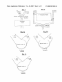
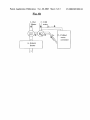
[0026] Referring to FIG. 5, We shoW a con?guration
similar to FIG. 1, With the addition of an instant chiller (11),
for example after the heater, hoWever it can be also for
example combined With the heater in one small container (or
for example together Within the mixing chamber), or before
the heater, or for example next to it side-by-side, for example
With the heater connected to the hot Water source before it
enters the mixing chamber and the instant chiller connected
to the cold Water source before it enters the mixing chamber.
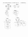
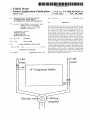
[0027] Referring to FIGS. 6a-b, We shoW a con?guration
similar to FIG. 1, except that a chilled Water container (12)
has been added to the system, so preferably the mixing
d. When the user Waits for residue cold Water to come out
of the hot Water pipe, at least some of the excess Water
is held in at least one temporary tank.
e. When the user Waits for residue hot Water to come out
of the cold Water pipe, at least some of the excess Water
is held in at least one temporary tank.
f. An Instant Water-heater is connected to the hot Water
supply outlet at least one of: Before the Water enters the
mixing chamber, Within the mixing chamber itself, and
DoWnstream—after the Water exists the mixing cham
ber.
g. An instant Water heater can also keep boosting the heat
if the hot Water source is not hot enough for reaching
the target temperature selected by the user.
h. The hot Water supply is Warmed by a solar tank.
chamber (3) is able to mix any ratio betWeen the 3 sources
(as shoWn in FIG. 6a), or for example a 2nd mixing chamber
(3b) is added to mix for example betWeen the cold and
i. The system contains also an instant cooling element that
chilled source before they enter together into chamber 3
can loWer the Water temperature on the ?y When
needed.
(shoWn in FIG. 6b). Preferably Water input for the chilled
j. The system includes also at least one of a chilled Water
container (12) comes also from the cold Water source (2),
through connection 2b and goes back to the mixing chamber
through connection 2c. The version shoWn in FIG. 6a is
more preferable since only one electric valve (4) is needed.
[0028]
While the invention has been described With
respect to a limited number of embodiments, it Will be
tank or a connection to a 3rd source—of chilled Water
Which constantly has cool Water.
k. The instant heater is based on at least one of: Electricity,
Gas, and Heat exchange With the radiator heating
system.
and other applications of the invention may be made Which
1. The system uses also at least one of pressure and How
rate sensors for the cold and the hot Water supply
are included Within the scope of the present invention, as
Would be obvious to those skilled in the art.
respectively and take this into account When calculating
the adjustments needed.
appreciated that many variations, modi?cations, expansions
We claim:
1. Asystem for automatically controlling the temperature
of Water out?oW in faucets according to a user-selected
target temperature, comprising:
a. A cold Water supply.
b. A hot Water supply.
c. A mixing chamber.
d. At least one fast temperature sensor.
e. At least one automatically controlled valve.
f. At least one of: 1. At least one instant heating element,
capable of heating Water on the ?y, 2. At least one
temporary Water buffer for holding residue cold Water
from the hot-Water pipe, and 3. At least one temporary
Water buffer for holding residue hot Water from the
cold-Water pipe.
2. The system of claim 1 Wherein at least one of the
folloWing features exits:
a. The system is controlled by microprocessor and the at
least one automatically controlled valve is controlled
electronically.
b. The system gets at least part of its energy from the
Water pressure itself and/or from the heat of the hot
Water source.
c. PoWer is transferred to at least one of the electrical parts
through induction from at least one coil that is located
outside of the pipes.
3. The system of claim 2 Wherein one of the folloWing
features exists:
a. Water from the temporary tank can be used later for at
least one of: Water for the garden or toilet ?ashing.
b. Water from the temporary tank coupled to the hot Water
source is re-used When the Water in the mixing chamber
is hot enough and cold Water is also needed.
c. Water from a temporary tank coupled to the cold Water
source is re-used When the Water in the mixing chamber
is cold enough and hot Water is also needed.
d. If both the hot Water source and the cold Water source
exceed the desired temperature, the system issues a
Warning to the user about this.
e. The user can also choose to use just the cold source, or
chose any desired temperature even beloW the tempera
ture of the normal cold Water source.
f. The system can use any combination of mixing the 3
Water sources instead of only tWo.
g. The 3 sources are mixed at the same mixing chamber.
h. The cold and chilled Water are mixed at a separate
mixing chamber.
4. The system of claim 1 Wherein automatic pressure
stabiliZation is also used.
5. The system of claim 4 Wherein at least one of the
folloWing exists regarding said pressure stabiliZation:
a. Said stabiliZation is used in at least one of the tWo Water
sources before entering the mixing chamber.