1
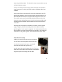
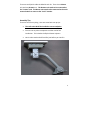
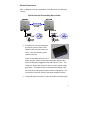
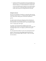
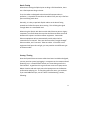
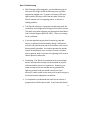
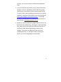
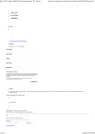
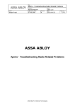
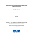
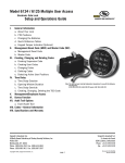
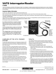
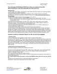
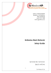
 ZipLink‐Xtreme
Ruggedized Wireless Ethernet Extender (Models# ZipLink‐X, ZipLink‐X200) User Manual v.7.1 Multi‐Link, Inc. 122 Dewey Drive | Nicholasville, KY | 40356 USA Sales and Tech Support 800.535.4651 FAX 859.885.6619 Copyright © 2014, All Rights Reserved, Multi‐Link, Inc. 1
Statement of Conformity Note: This equipment has been tested and found to comply with the limits for a Class A digital device, pursuant to part 15 of the FCC Rules. These limits are designed to provide reasonable protection against harmful interference when the equipment is operated in a commercial environment. This equipment generates, uses, and can radiate radio frequency energy and, if not installed and used in accordance with the instruction manual, may cause harmful interference to radio communications. Operation of this equipment in a residential area is likely to cause harmful interference in which case the user will be required to correct the interference at their own expense. This device complies with Industry Canada license ‐exempt RSS standard(s). Operation is subject to the following two conditions: (1) this device may not cause interference, and (2) this device must accept any interference, including interference that may cause undesired operation of the device. Terminology:
Master – This is the radio that goes where you already have internet
service or the main office.
Remote – This is the location where no network service currently
exists.
2
Technical Support Contact:
1‐800‐535‐4651 techsupport@multi‐link.net *Safety Warnings for Grounding and RF exposure* In order to comply with electrical codes in most areas, as well as provide adequate protection from lightning, you MUST ground the ZipLink outdoor unit! This device contains a low power radio transmitter. When this device is connected and transmitting, it sends out Radio Frequency (RF) signals. This Wireless Radio device has been evaluated under FCC Bulletin OET 65C and found to be compliant to the requirements as set forth in CFR 47 Sections 2.1091, 2.1093, and 15.247(b)(4) addressing RF Exposure from radio frequency devices. The radiation output power of this wireless device is far below the FCC radio frequency exposure limits. Nevertheless, this device should be installed and used in such a manner that limits the potential for human exposure to distances greater than 20 cm or 8 inches from the device. This device should not be installed within 10 meters / 30 feet of any other RF transmitter. 3
Contents
Terminology:................................................................................................2 Technical Support ........................................................................................3 Safety Warnings for Grounding and RF exposure .......................................3 Contents ......................................................................................................4 Introduction.................................................................................................5 Box Contents................................................................................................5 Cabling .........................................................................................................5 Cable Gland Assembly .................................................................................6 Bench Testing ..............................................................................................7 Installation ...................................................................................................8 Assembly Tips ..............................................................................................9 Electrical Connections ...............................................................................11 Aiming the antennas..................................................................................12 Bench Testing ............................................................................................13 Startup / Testing ........................................................................................13 Warranty....................................................................................................16 Disclaimer ..................................................................................................16 Specifications.............................................................................................17 4
Introduction The Multi‐Link ZipLink‐Xtreme is a wireless communications system that provides an Ethernet LAN (internet) connection to be quickly installed between two buildings or locations up to 3 miles / 5 kilometers apart. The ZipLink‐Xtreme is designed to be easy to install. You will need the following tools: ‐
‐
‐
Power Drill / Screwdriver w/ Phillips bits 10mm nut driver / wrench Electrician’s fishline Box Contents The ZipLink‐Xtreme box contains the following: ‐
‐
‐
‐
2 ZipLink‐Xtreme Outdoor Radios, Master & Remote 2 power adapters and Power Injectors 2 Antenna Mounts Accessory Kit Cabling Each ZipLink‐Xtreme radio comes equipped with 30 Meters / 100 feet of OUTDOOR RATED cable which runs from the ZipLink to the Power Injector, which is usually mounted in the telco room. The cable is used for the data connections as well as power. YOU MAY SHORTEN THIS CABLE IF YOU WISH, BUT YOU MAY NOT LENGTHEN IT. Keep in mind that this cable length maximum distance is due to the maximum length allowable for the power wires inside this cable only. The cable length FROM the Multi‐Link power injector RJ45 connector TO the main internet connection or switch/router may be up to 300 feet in total using Cat5e or Cat6 for Ethernet/data, or even greater distances 5
when using shielded cables. This allows for almost any installation to use the ZipLink‐Xtreme system. There is one black connector coming out of the ZipLink. This weather‐
proof connector is for the 4 pair Cat5e outdoor rated data cable that is included. Each outdoor ZipLink radio should be electrically grounded by use of a ground lug installed on one of the bolts used to hold the ZipLink on the pole mount brackets and run to a proper electrical ground. This is not only a safety requirement for lightning dissipation purposes, but also improves system radio performance, since the enclosure provides radio shielding against unwanted radio and electrical noise on the Ethernet connection. Assuming that the outlet which the Multi‐Link Power Injectors power supply is properly installed according to electrical codes, no further grounding points in the system is required. The electrical circuits for the Ethernet/data connections should NEVER be grounded. This includes all connections in the power injector. Ethernet connections must “float”. Cable Gland Assembly Inside the accessory box that came with the ZipLink, you will find 2 black cable glands that look like this: You should unscrew the two parts. You should leave the small rubber O‐ring where it is. You will notice that the O‐ring has a slit in it. This is to allow the Ethernet cable to be completely assembled on the ground, prior to installing it on the radio. 6
This is the correct order for the cable gland components on the cable: The next step is to push the rubber ring into position so that it will compress when the gland is assembled. You should GENTLY use a small screwdriver to slide it inside the main body of the gland housing until it is flush with the little plastic fingers at the bottom of the gland, like shown in the picture to the right: You can now slide the gland up and down the cable while you plug in the Ethernet connector into the bottom of the radio: Screw in the gland housing: And then the bottom gland cap: 7
Bench Testing When bench testing the ZipLink, you need to know the following: ‐
The minimum distance between the radios must be 25 feet or 8 meters. If you have the Master and Remote ZipLink closer together than this during testing, the system may not operate properly, especially for VoIP services testing. ‐
You should always orient the radios similarly to how they will be oriented when they are installed. Optionally, you may sit them BOTH sideways with the SKY arrow pointing at the same wall to facilitate easy RJ45 cable installation. ‐
Both units should be electrically grounded on their chassis to ensure noise from lights and motors in the vicinity do not affect signal quality. Installation Mount the ZipLink Radios as high up as possible on both buildings. The radios must “see” each other without obstructions between them, and since radio travels in a “football” shape between antennas, you must not only have a direct path between the antennas, but the path also must be wide enough, as determined by the distance between the radios: Radio height required by distance between radios Distance (mi./km) .25 / .40 .5 / .80 Minimum Height( ft/m) 10 / 3 14 / 4.3 1 / 1.6 19 / 6 For example, if you have two buildings a half mile apart, the ZipLink radios should be 14 feet above the ground, plus the height of anything else that is in between the buildings. So, if there are vehicles moving between the radios, they need to be 14 above the maximum height of the traffic, approx. 30 feet up. Same rule applies for trees, buildings, and other structures. 8
There are two ZipLink radios included in each kit. There is one Master unit and one Remote unit. The Remote unit needs to be connected to the “remote” end. The Master unit needs to be connected to the main network switch or router at the “main” location. Assembly Tips There are two of everything. Here are some basic set up tips: •
The radio units MUST be installed at correct endpoint. •
You can use any other component at either end of the installation. This includes the ZipLink Power Injectors •
Here is what each end will look like just before you install it: 9
•
First, attach the aluminum bracket to the back of the ZipLink. Use the (4) 10mm bolts, washers, and lock washers provided: •
Next, put the U‐Bolts in place. These are also packaged in the Accessory Kit and are wrapped in plastic wrap, along with washers and lock washers: The hardware for the pole mounts is included with the brackets themselves. Included are three bolts‐‐‐2 short, square‐
flanged bolts and one long pivot bolt‐‐‐with nuts. 10
Electrical Connections Here is a diagram of all the components in the ZipLink kit, and how they connect: ZipLink Electrical Connectivity (Not to Scale) •
The electrical connection between the power injectors and the wall adapters have not been shown for clarity. Here are what the power injectors look like: There are two RJ45 connectors on a power injector. Please ensure that the outdoor ZipLink radio Ethernet cable gets plugged into the side that says “PoE”. This stands for “Power over Ethernet” and is how the outdoor radio gets power. The Ethernet jack on the other side labeled “LAN” will connect to your laptop, Ethernet switch or equipment. The round barrel connector is where the power adapter connects. •
It does not matter the order in which the radios are powered up. 11
•
The RJ‐45 connection on the Master side may be plugged into an office router, etc. If the Remote RJ‐45 connection is to be shared between computers, it is recommended that it is routed as well, to ensure LAN traffic between computers at the remote end does not go “over the air”, thereby affecting the performance of the wireless LAN connection by relaying unnecessary LAN traffic. Aiming the antennas Once you have completed the installation, try to get both radios pointing at the other as best as you can. It is essential that the radios are mounted in such a way that the cabling comes out the bottom (towards the ground). The ZipLink antennas allow up to 15 degrees variation in between the Remote and Master units left/right and up/down. Your aiming does not have to be perfect to have the system work. You can essentially “eyeball them in” and get a good, stable signal. For example, if your ZipLink Remote and Master units are 500 yards/meters apart, and one is mounted 5 feet higher than the other, and the left/right angle is out by 3 or 4 degrees, you will still have a good stable link. The TUtil ZipLink Utility software can assist you in getting the best signal possible. The latest up‐to‐date software may be acquired from Multi‐Link Technical Support (800‐535‐4651). There is no charge for this software. 12
Bench Testing When bench testing the ZipLink prior to doing a field installation, there are a few important things to know. First, the radios are designed to be at least 20 feet apart when in operation. It is possible to overdrive the radios if they are only a few feet apart and facing each other. Generally, it is okay to put both ZipLink radios on the bench facing upwards and a few feet apart when testing. This will bring the signal strength down to a reasonable level. When using the ZipLink with devices with older Ethernet ports or legacy computers, be careful about the way that the Ethernet cables are wired between the injectors and the customer equipment. Some older Ethernet equipment will not automatically switch when the line connections are reversed. There are what are called “straight through” Ethernet cables, and “crossover” Ethernet cables. If the LEDs on the equipment RJ45 ports do not light, you may need to use a different type of Ethernet cable. Startup / Testing Once the ZipLink Ethernet‐Xtreme radios have been installed and aligned, you may test the system by plugging in a computer at the remote end and powering it up. It should behave exactly as if it was being used in the main location. A good check is to get internet access on a laptop at the Master location end and simply move the laptop across to the Remote end location and plug it in. If everything works the same, you are done. If you need additional tips, see the “Basic Troubleshooting” section, following. 13
Basic Troubleshooting •
With Ethernet cables plugged in, you should always get at least one LED to light up on the Ethernet ports you have equipment plugged into. If you do not see any LEDs that light up when you plug in the Ethernet cable, either the ZipLink outside unit is not getting power, or there is a cabling problem. •
TUtil ZipLink software is a program that will assist with the installation and configuration settings of the ZipLink system. The latest up‐to‐date software may be acquired from Multi‐
Link Technical Support (800‐535‐4651). There is no charge for this software. •
If you are experiencing any kind of stuttering, sporadic service, or general bad voice quality during a VoIP phone call, this may indicate that one of the outdoor units has not been properly grounded. You need to ground the outside chassis of the outdoor units in order to ensure a suitable path to ground, both in the case of a lightning strike, and to reduce spurious radio noise. •
Grounding – The ZipLink is considered to be a low voltage device, and therefore usually may be installed by anyone without need for permits or inspections. However, you need to make certain the outside case is grounded for lightning reasons, and you should consult your local electrical / safety codes in your area prior to performing any kind of permanent equipment installation. •
It is important to understand that each ZipLink system is programmed to ONLY talk to itself. If you have two ZipLink 14
systems, you cannot mix and match Remote and Master units. •
If you are experiencing unclear voice or data performance problems, there is a possibility that the ZipLink is getting interference from another wireless network near the site. To check if this is the case download and install on a laptop computer a program called inSSIDer from the following link: http://www.metageek.net/products/inssider/ . If you need assistance, contact Multi‐Link Technical Support directly 1‐
800‐535‐4651; techsupport@multi‐link.net •
Should you wish to remove the original ZipLink sticker from the front of the outdoor unit, and replace it with something else, please ensure that anything installed on the front of the ZipLink radio allows high frequency radio to pass through. You cannot use labels that have any kind of metallic based inks, or a foil label without harming the ZipLink, or seriously degrading its performance. 15
Warranty Multi‐Link warrants the ZipLink system for one year from date of purchase by the original owner. Multi‐Link will replace or repair, at its option, any ZipLink system that fails to perform under normal use, provided that the system is returned, at the cost of the owner, to Multi‐Link. Items that are returned for warranty repair must be accompanied by a copy of the original invoice or proof of purchase. For further details about how to receive warranty or after warranty service information, please contact Multi‐Link Technical Support at 1‐800‐535‐4651; techsupport@multi‐link.net Any operation of the ZipLink outside of specified temperatures, power, environment, or in a manner specified in this manual as harmful to the device will void any warranty. Additionally, any attempted repair or dismantling of any Multi‐Link product, in any way, will void all warranties. In no event shall Multi‐Link liability exceed the original purchase price of the product from direct, indirect, special, incidental, or consequential damages resulting from the use, or misuse, of this product. Disclaimer Installation of this equipment must be in strict accordance with the instructions included in this documentation. Any changes or modifications made to this device that is not expressly approved by Multi‐Link may void the user’s authority to operate the equipment. 16
Specifications Radio Range 3 Miles / 5 kilometers Ethernet Port RJ45 Over the air data rate ZipLink‐X: Up to 80Mbps ZipLink‐X200: Up to 200 Mbps Operating Temperature ‐40F to +145F (‐40C to +60C) Power Required 19W maximum, 10W typical Radio Type 5.8 GHz DSSS, License Free Encryption 256 Bit WPA‐PSK (AES) Radio Power +40 dBm (adjustable) Radio Sensitivity ‐80 dBm @ 10‐5 BER Outdoor Unit Size 12” x 12” x 3.5” (31cm x 31cm x 9cm) System Shipping Weight 23 lbs / 10.5 kg 17
ZipLink Series ‐‐ Available in these Models: ZipLink‐1: Extend a Single analog POTS line AND 12 Mbps of Ethernet up to a mile ZipLink‐2: Extend Two analog POTS lines AND 12 Mbps Ethernet up to a mile ZipLink‐E: Extend 40 Mbps Ethernet up to a mile ZipLink‐X: Extend 80 Mbps Ethernet up to 3 miles ZipLink‐X200: Extend 200 Mbps Ethernet up to 3 miles Contact Info for Data Sheets & Pricing
Multi‐Link, Inc.
122 Dewey Drive Nicholasville, KY 40356 800.535.4651 x225 sales@multi‐link.net 18
When using your telephone/electrical power equipment, basic safety precautions should always be followed to reduce the risk of fire, electric shock and injury to persons, including the following: 1. Read and understand all instructions. 2. Follow all warnings and instructions marked on the product. 3. Unplug this product from the wall outlet before cleaning. Do not use liquid cleaners or aerosol cleaners. Use a damp cloth for cleaning. Let dry thoroughly before plugging device back into 120 Volt outlet. 4. Do not use this product near water, for example, near a bathtub, wash bowl, kitchen sink or laundry tub, in a wet basement, or near a swimming pool. Do not use this product outdoors. 5. Do not place this product on an unstable cart, stand, or table. The product may fall causing serious damages to the product. 6. This product should never be placed near or over a radiator or heat register. This product should not be placed in a built‐in installation unless proper ventilation is provided. 7. This product should be operated only from the type of power source indicated on the marking label If you are not sure of the type of power supply to your home, consult your dealer or local power company. 8. Do not allow anything to rest on the power cord to phone lines connected to locate this product where the cord will be abused by persons walking on it. 9. Do not overload wall outlets and extension cords as this can result in the risk of fire or shock. 10. Never push objects of any kind into this product through cabinet slots as they may touch dangerous voltage points or short out parts that could result in a risk of fire or electric shock. Never spill liquid of any kind on the product. 11. To reduce the risk of electric shock, do not disassemble this product, but take it to a qualified serviceperson when some service or repair work is required. Opening or removing covers may expose you to dangerous voltages or other risks. Incorrect reassembly can cause electric shock when the appliance is subsequently used. 12. Unplug this product from the wall outlet and refer servicing to qualified service personnel under the following conditions: 19
A) When a power supply cord/plug or phone line cord connected to the product is damaged or frayed. B) If liquid has been spilled into the product, but it is thoroughly dried out. C) If the product has been exposed to rain or water, but it is thoroughly dried out. D) If the product does not operate normally by following the operating instructions, adjust only those controls that are covered by the operating instructions because improper adjustment of other controls may result in damage and will often require extensive work by a qualified technician to restore the product to normal operation. E) If the product has been dropped or the cabinet has been damaged. F) If the product exhibits a distinct change in performance. 13. Avoid using a telephone (other than a cordless type) during an electrical storm. There may be a remote risk of electric shock from lightning. 14. Do not use the telephone to report a gas leak in the vicinity of the leak. 15. Do not touch or attempt to unplug this product from the wall outlet if: A) Liquid has been spilled into the product and it is wet or suspected to be wet. B) The product has been exposed to rain or water and it is wet or suspected to be wet. INSTALLATION INSTRUCTIONS 1. Never install telephone wiring during a lightning storm. 2. Never install telephone jacks in wet locations unless the jack is specially designed for wet locations. 3. Never touch uninsulated telephone wires or terminals unless the telephone line has been disconnected at the network interface. 4. Use caution when installing or modifying telephone lines. Copyright © 2014, All Rights Reserved, Multi‐Link, Inc. 20