1
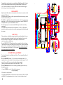
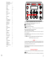
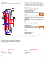
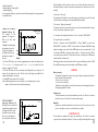
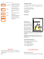
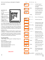
Lunde 2001-01-09
CONTENTS
Side
Installation
Buttons
Symbols
Start up
Winding on the line
Some explanations
Programming
Description of programs
Normal Fishing
Step Jig Fishing
Bottom Fishing
Bottom Fishing w. step
Squid fishing
Display texts
Security lock
Errors
Maintenance
Technical data
Accessories
Warranty
Register A- Z
20
2
2
3
3
3
4
5
6
6
6
7
8
8
9-14
15
15
16
17
17
18
19
1
Congratulations, you have made a very good choice of jig fishing machine. Belitronic
have developed and manufactured electronic Jig Fishing Machines for more than 27
years. Thousands of machines are used in 56 different countries worldwide. Biggest
sales in Norway, Faeroe Islands and Iceland.
wewrtrtt
DECLARATION
Björn Neuendorf AB, Lunde, Sweden manufactures this machine in accordance with the
appropriate EC-directive.
Serial number can be found on a yellow sign outside and beneath the emergency button
also at the inside under the gear.
The BJ5000 is a jig-fishing machine and it should not be used for any purpose other
than fishing. It is also very important to place the machine so that the EMERGENCY
STOP push button is easy to reach should the need arise.
The undersigned gives an assurance that the BJ5000 co mplies with the stated safety
requirements.
The machine must be connected to lead accumulators of 12 or 24 volts. The machine
must only be used by persons who have read this operating manual and fully understand
the contents.
MOUNTING
Take particular care with both the mechanical and the electrical installations. If you are
uncertain, contact authorized personnel for the electrical installation. Always use the
shortest possible power supply cable. Avoid cutting the cable, and do not fit
unnecessary connectors and junctions.
Press the EMERGENCY STOP push button before connecting the cable to the battery.
Connect the power supply cables directly to the battery as follows: Connect both the red
leaders to battery (+) positive pole and both the blue leaders to (-) negative battery pole.
These connections apply for either 12 or 24 volt systems. Never use any other power
source other than regular lead accumulators.
PUSH BUTTONS and SYMBOLS
Twelve push buttons make your fishing more efficient. They are grouped logically and
are easy to use.
Z- button ZERO SET functions. 1) To zero set the electronic depth counter. 2) In
stopped mode; to reset the machine to factory settings by pressing it for approx. five (5)
seconds. Very useful if for any reason the machine behaves strangely.
Valid only for values inside parentesene on the side DISPLAY TEXS
P-button PROGRAM button is used to enter the programming sequence and to step
through the programs.
↵- button ”ENTER” is used to: 1) Enter the first main menu
2) Exit programming.
+/- buttons have triple functions:
1) In normal or fishing mode (AUTO) to increase or decrease values of PULL, CATCH
and BRAKE. 2) In programming mode to select on of six items from the main and
2
19
Battery warning
Beeper (Sounder or Pip)
Bottom Fishing
Buttons
Catch
Code
Display
Display texts
Enter (↵)
Errors
Factory settings
Free run
Info
Installation
Jig
Light
Line, Spooling on
Low Boat battery
Maintenance
Memory mess
Mess on line
More
Motor
Normal fishing
Pause
Pip
Programming
Programs
Push buttons
Ret
Reverse rotation
Security lock
Speed brake
Squid
Start
Step Jig Fishing
Symbols
Technical data
Warranty
Winding on the line
Wheel
15
5
7
2
5
5, 15
5
9-14
3
15
4
4
5
2
6
4
4
15
16
15
4
5
5
6
5
5
5
6
2
6
4
15
4, 5
8
3
6
2
17
17
3
5
secondary menus. 3) In programming, settings of values. The left pair changes the
100th, the middle pair the 10th finally the right pair the single or 1/10th.
- symbol means PULL. (Clutch symbol)
- symbol means BRAKE.
- symbol means CATCH-sensitivity
A-button START of program = AUTO mode. As long as the button is pressed, the
brake is not applied to the wheel, and it can freewheel.
↑-button is used to haul in the line manually
NOTE! A slow push on the button will make the motor run but only for as long as the
button is kept pushed. .
A very rapid push on the button will make the motor run continuously. Another push on
the button will stop the motor.
↓ - STOP-button: 1) Stops everything, programs, manual running of the motor, etc.
2) BRAKE function as long as it’s pressed.
START
Turn on the machine by turning the EMERGENCY STOP push button lightly clockwise
until it pops out. The machine is now powered. Watch the display during start up as it
provides information from the first few seconds.
NB! If the display is dark; the machine is incorrectly connected to the battery. Switch
polarity on the battery
WINDING ON THE LINE
1. Tie the line safely to the wheel. Set PULL to minimum by pushing the -button under
- symbol.
2. Push the ↑-button rapidly. The motor will now run continuously, but without any
18
3
power to the wheel.
3. Increase PULL by pressing the + button under the
- symbol until a smooth pull
is applied in the line.
4. When all the line is wound on, press STOP-button to stop the machine and then press
the Z- button to reset the electronic counter.
5. Don’t forget to set the correct line diameter and the diameter formed by the outermost
turn of line. Measurement of the line will be done under the menus ”WHEEL” and
”NYLON”. To help find the correct diameter of the wheel after the line is wound on,
there are some figures on the outside of the wheel i.e., 160,180 and 200. These values
are in millimeters. If the outside diameter of the line on the wheel falls in between these
numbers, the diameter can be estimated using the figures as a guide.
average during fishing:
Operating voltage:
Cable dimension (max 10m):
Line capacity @ Ø1,4
2- 5A
12 - 30 volts
4*2,5 mm²
>500 m
ACCESSORIES
Cover
Pole Ø40*1150 mm Aluminum pipe
Outrigger Ø30*1150 mm Aluminum pipe
Outrigger holder for placing the outrigger on top of machine.
Extra long cable
SOME EXPLANATIONS
Factory settings: Basic program of the machine. Average values are chosen at the
factory to enable the machine to work without any further programming. Therefore
before you start fishing for the first time only Depth and Jig length have to be set.
Catch and Alarm Beeper (Sounder): A built in beeper sounds when the catch is
hooked. When the catch is at the surface a slower beep will sound. Press STOP-button
to silence the beeper. The beeper will also sound warnings.
Light: Four built in LEDs signal catches and warnings in conjunction with the sounds
of the beeper.
Speed brake: This brake function is activated if the sinker pulls out the line too rapidly.
A maximum allowed speed can be set together with the braking power when fishing.
Factory settings are 600 rpm, 20% braking power and activating time 1,0 sec.
Fishing Line Tangles (Mess): Sometimes lines from two or more machines become
entangled. If the sinker and the hooks are tangled in an other machine and that machine
pulls up the lines, the ”hooked” machine will normally do nothing and its line will float
around in the sea exposed to other lines and hooks. If the ”MESS” function is on, the
“hooked” machine will register that it has lost the load (sinker and catch) on its line and
will automatically wind up the line.
WARRANTY
v Guarantee of this machine is one year (two in Nordic countries) from day of
purchase, covering production- and material faults. Invoice or receipt is
accepted as warranty notes.
v Substitute machines from local dealer may be available during repair period.
v During warranty period (1 year) repair is free of charge and afterwards repair is
made at fixed prices.
v Warranty does not cover any assembly, dismantling or transportation costs.
Neither damage caused by improper handling or wrong mechanical or
electrical installation.
v Warranty does not cover damage caused by defective or bad batteries or
alternators.
v Warranty does not cover loss of catch.
v Save the original box if the machine has to be sent to dealer or factory.
We would be more than glad if you write to us and tell about your experience both
positive and negative. If you do, please enclose a picture of your boat showing our
equipment.
Every year we will premiere one fisherman that has sent us any material regarding
our machine.
Reverse wheel rotation: It is possible to change the hauling direction of the wheel. Take
of the cabinet, swap the cables from the motor on the PC-board. Now the motor will run
the other way. To obtain the counter to count the other way, enter the the menu. ↵ WHEEL - COUNTER – P - any of the three + buttons. You will now read “Reverse” in
the lower line of the display. Press ↵ to exit programming.
Register A – Z
PROGRAMMING
Red Push Buttons are used in programming. At delivery, every BJ5000 is preprogrammed (factory set) to work like the previous famous old BJ5. However you can
4
Accessories
Page
17
17
a couple of times per year.
If the friction surface is sticky use any solvent. Then use an emery cloth to rub the surface a
little.
If the machine needs to be or has been stored and unused for a long periods, clean the
clutch and loosen the box.
adjust the behavior of your BJ5000 to suit your particular fishing requirements.
The P-button provides access to the most necessary functions in each program. More
advanced functions will be found under the main-menu which is reached by pushing the
↵ -button in position “LINE OUT”. Pressing the corresponding +/- buttons gives a
choice from six different items.
MOTOR: values for accelerations and speeds at jigging, at the
instant of catching, when hauling up the catch, during line
tangles and when manually hauling in the line.
PAUSE: different pauses in the programs
CATCH: detecting times and sensitivity of catch. The calibrated value can seen and can
MOTOR PAUS CATCH
be adjusted.
WHEEL BRAKE MORE
WHEEL: Width of wheel. Diameter of the outermost turn and of the line on the wheel
and the diameter of the line wound on the wheel. The number of revolutions of the
wheel counter. Pulses from sensor. Position for stop 1) at surface with soft stop function
or 2) at wheel stop.
SPEED BRAKE: power, time and speed of brake function. Number of free wheel
turns.
MORE: means jump to main menu 2 with more functions.
DISP: contrast, brightness and light time of the display.
Language. Viewing time for DRAG - CATCH - BRAKE
values after last pushed button.
INFO : information about boat battery voltage measured inside
the machine.
DISP INFO
PIP
Temperature and humidity inside the machine. Current measuring onKODE
electronic unit RET
and
motor.
PIP (sound) at button pushing, at catch and when catch at surface.
EXTRA: choice of extra equipment.
CODE: security locking code system.
RET: Return to main menu no. 1.
After one of the main functions above has been selected, use the P-button to scroll. Use
the ↵-button to exit to normal menu ”LINE OUT”.
Also regularly check the value of the humidity. Enter the INFO menu and note the
figures. If the value is decreasing, this is an indication that the humidity has increased
inside the box. Open and check.
TECHNICAL DATA
Weight:
Power consumption: max
16
11,2 kg
30 A @ 12 volts
15 A @ 24 volts
PROGRAM DESCRIPTION
The BJ5000 has five basic programs.
* Normal jig fishing (N)
* Step Jig (S)
5
* Bottom fishing (B)
* Bottom fishing w. Step Jig (BS)
* Squid fishing (Sq)
Every program is built up by steps and a more detailed description of each program and
its contents follows.
NORMAL JIG FISHING
Normal fishing (N)
The simplest of the
programs. See diagram 1.
Built up by three main
sequences:
Regular fishing
When locked there will be only three tries to open it. Then the battery cable must be
disconnected from the battery for more than one minute before three more tries can be
attemted
1) Activate at: ”Power up”
The machine will be locked as soon as the emergency push button is pressed. Obviously
it will be locked when the power is disconnected from the machine.
2) Activate at: ”Battery disconnected”
The machine will only be locked when the power cable is disconnected from the battery
or if the boat battery voltage drops very low.
Diagram 1.
To de-activate the locking functions choose ”Never” from the ”CODE MENU”.
Depth
1. Depth the fishing depth
Jig
the machine will work at.
2.
is the
amplitude
i.e., during which the machine is stopped from the moment the
3. Jig
Depth
Pause
is the time
Depth pause
Time
the
depth
range
of
the
updepth until hauling restarts.
lures reach their chosen
and down movement of
the
lures.
Programming
”Regular Fishing”
1. Push the P -button to go into the programming mode check that display shows
”Fish method (N)” in upper row and ”Normal fishing” in the lower. If not,
change by using the +/- buttons.
2. Push the P -button once more and adjust the fishing depth by pressing the +/buttons. All six buttons can be used. The left ones for 100-settings, the middle for 10settings and the right for 1-settings.
3. Push the P -button again select ”Jig length”.
In the following diagrams you can see a picture, as it would appear in your echo
sounder, of the movement of the sinker during fishing
The personal code is set as follows:
Push the ↵ button to enter the MAIN-MENU 1. Choose ”MORE” to get the next
MAIN-MENU 2 and choose ”CODE”. Select with the +/- buttons of BRAKE locking
method according to your wishes. Push the P-button to select a personal code. Use the
+/- buttons of BRAKE to change the figures and the +/- buttons and of CATCH to
select position (move sideways). When the correct code is found press the P-button to
confirm and the ↵-button to exit.
When the machine is turned on and the code lock is activated the display shows CODE?
Press the P-button and enter the code and press the P-button to confirm.
ERRORS
Battery warning
The machine continuously measures the supply voltage and signals an alarm if it
drops below the following voltages:
10 volts in a 12-volt system
15 volts in a 24-volt system.
Insufficient voltage might be caused by bad connectors, bad or damaged cables loss
of charging equipment or similar.
Memory mess
The built in memory has some bad information in some cells. Press the ↵-button to
proceed. Factory set values will be written into the memory.
Step Jig Program
STEP JIG FISHING
Diagram 2
Step Jig Fishing (S)
Basically this is the same as the
regular fishing method, but the
Jig length is divided up into
Depth
Step Lenght
steps and between each step
sounder during fishing. Two new functions are added to the regular fishing program:
Jig
there
is Jig
a pause.
Diagram
2
1. Step
Length
is the depth
of each step of the Jig length.
shows the picture of the echo
2. Step Jig Pause is the pause between the Step
Jig Lengths.
Step Pause
Depth Pause
6
Time
Humidity
Open the case and check whether there is water in it or not. If it is necessary to dry it
out, use a hair dryer to remove as much moisture as possible
MAINTENANCE
The machine does normally not require any maintenance. The clutch is somewhat
exposed to water and outside pollution. To ensure a perfectly functioning clutch, clean it
15
Pictures
Min Max Fact. Step
LOW BOAT BATTERY
Push button ↵
Read only WARNING
MEMORY MESS
Push button
Version X.X
System XXV
↵
Read only
Read only
Read only
Serie No:
XXXXXX
Overload !
Notes
Confirm by pressing the ↵ button.
CHECK THE BATTERY SYSTEM!
A warning. There might be some mess
data in any me mory cells. Push the ↵
button. Factory set will be done.
Second picture from start up, showing
program version and boat voltage
system.
Third picture showing serial number
appears at start up.
This information is given if the wheel
stops outside the s elected fishing
depth, or outside maximum set depth
in Bottom program.
Programming Step Jig Fishing
1. Push the P -button to enter the programming mode. Select the program by using the
right +/--buttons. Read ”Fish method (S)” in the upper row and ”Step
fishing” in the lower row of the display.
2. Push the P -button again and select ”Depth”
3. Select ”Jig length”.
4. Decide the ”Step length”.
5. Select ”Step pause”.
BOTTOM FISHING
Bottom Fishing
Diagram 3
Bottom Fishing (B)
Means fishing close to bottom. See
No of Jig
diagram 3. The machine will hold the
sinker close to the bottom even if the
depth changes over time. Fishing
Jig
depth can be chosen. Three new
Depth
dist.
turn.
functions
Whenisthe
added
linetoisthis
reeled
program:
out the wheel rotates at aBottom
speed
of many Pause
turns per second,
Detect
timerapidly or stop. When the
but
1. Detect
when time
the sinker
is the time
hits the
the bottom
machineit will slow down
very
Time
rotation
is sothe
slow
that one
takes to speed
recognize
bottom.
It isturn of the wheel takes more time than the selected for
DETECT
TIME,
thewheel
machine
recognizes
this as a sign that the sinker has reached the
equal to the
time the
makes
one
bottom. Immediately it starts winding up the total of the length of BOTTOM DIST. +
JIG LENGTH.
2. Bottom dist. is the depth at which the fishing shall be undertaken over the bottom.
3. No of jigs. This is the number of jigs that the machine will make before it will try to
find the bottom again.
Programming the Bottom Fishing Program
1.
2.
3.
4.
5.
SECURITY LOCK
The machine is equipped with locking system. The lock can be activated in two ways.
1) When the machine is turned off by the Emergency breaker or, 2) when the battery
cable is disconnected.
14
Press “P” once and select fish method ”Bottom fishing (B)”.
Press “P” again and select ”Jig”.
Press “P” again and decide ”Detect time”.
Press “P” again and decide ”Bottom dist.”.
Press “P” again and select ”No. jigs”.
BOTTOM FISHING WITH STEP JIG
Bottom fishing and step (BS)
A combination of bottom fishing and step jig fishing program. Two new functions are
7
added to the regular bottom-fishing program: ”Step Jig Length” and ”Step Jig Pause”.
SQUID FISHING
Squid Fishing
Squid fishing (Sq)
Diagram 4
See diagram 4.
The program is built up of four
components.
Min depth
1. Depth is the first (start) depth the
machine is selected to fish at.
Depth
2. Depth reduc. is the reduction of
Depth
reduc.
depth the machine makes every time
depth
the line
as islong
paidasout
theuntil
value- not is changed or the program is stopped and started again.
3. Min.depth is reached. The
Time
E.g.
If depth
selectedtotofish
50 at
fathoms,
”Depth reduc” is set to 5 fathoms and ”Min.depth”
machine
williscontinue
this
is set to 30 fathoms, following happens when the program is started: 50 fathoms of line are
reeled out. Clutch is activated and the machine starts to haul in all the 50 fathoms. All line
and lures are wound up on the wheel and the line is reeled out again, but this time to 505=45 fathoms. Line is reeled in and next time it is goes out it will go out to 40 fathoms and
so on two more times until the ”Min.depth” (30) will take over. The machine will then fish
at depth of 30 fathoms. If the STOP button or START button is pressed, the machine will
start fishing from 50 again.
4. Square wheel is special function for squid fishing. When it is activated, the motor will
run intermittently i.e., it will alternate between two different speeds, SPEED 1 and SPEED
2, to simulate the motion of the line being wound up on a square wheel. This intermittent
hauling of the line is best fishing method for catching squid. The varying of the motor
speed automatically switched off when many squid are on the hooks.
Pictures
Min Max Fact. Step
INFORMATION
Humidity
XXX
Alarm limit
humidity
XX%
0
30
1
Read only
ALARM! HUMIDITY
LIMIT EXEEDED!
Read only
INFORMAtiON
Motor(Amp)
XX
OUT
IN
IN
Beep ‘on’ or ‘off’, at button pressing.
OUT
99
30
1
Select how many beeps at catch.
2
60
5
1
Aldri
Batt
Select the pause between every single
beep when the catch is at the surface.
Select when security code shall be
activated. Never - At Power up - If
battery has been disconnected.
Select a personal code. Six digits.
2
Bars shown when any of the +/DRAG-buttons are pressed. Amp
shows the actual current of the motor.
Shown when any of the Catch-buttons
are pressed. One unit = 1 ampere.
Shown when any of the Brake -buttons
are pushed.
First picture that appears when the
machine is turned on, or when the Zbutton is pressed 5 sec. for reset.
Second picture witch appears if the Zbutton is pressed for more then 5
seconds.
Show at which depth the catch was
detected. Is shown altered with the
Depth counter.
PIP AT BUTTONS
XXX
PIP AT CATCH
No
XX
Påslag
PIP AT SURFACE
No
X.X
0000000 999999
CODE AT.
XXXX
0
CODE ?
XXXXXh
100 18
XXXXXX
----------<Drag
----------<Amp
Programming Squid Fishing
0
0
1 Push the “P”-button to select ”Fish program Sq”. ”Squid fishing” shall appear in the
lower row of the display.
2 Push the “P”-button again and select ”Depth”.
3 Push the “P”-button and select ”Depth reduc”.
4 Push the “P”-button and select ”Min.depth”.
5 Push the “P”-button and select ”Square wheel” on or off. If on:
6 Push the “P”-button and select ”Speed 1”.
7 Push the “P”-button and select ”Speed 2”.
99
Notes
and open box and check for leakage.
Settable limit for humidity. If
exceeded, alarm will be raised by
sound and light.
Allowable humidity limit inside the
box is exceeded. Acknowledge by
pressing ↵. If the alarm goes on for
the second time, the box must be
opened, checked and cleaned.
Shows the motor current.
----------<Catch
----------<Amp
50
7
1
100 30
2
Read only
------- ---<Brake
----------<Amp
belitronic´s
BJ500X
Read only
Read only
Factory set
values
DISPLAY TEXTS
Catch depth
8
XXX
Read only WARNING
A warning. Boat battery is bad or
other malfunction of electrical system.
13
Pictures
Min
0
Soft stop at 0
in manu
XX
RP-card
T1 @ 12V
XXX
RP-card
T2 @ 12V
XXX
RP-card
Puls @ 12V
XXX
RP-card
T1 @ 24V
XXX
RP-card
T2 @ 24V
RP-card
Puls @ 24V
SPEED LIMIT
Brake Power
SPEED LIMIT
Brake time
SPEED LIMIT
Max speed
DISP
CODE
INFO
XXX
XXX
XX%
X.X
XXX
PI P
RET
DISPLAY
Contrast
XX%
DISPLAY
Brightness
XX%
DISPLAY
Light time
XX.X
Notes
Pauses between demagnetizing pulses
in 12 volt system. One unit = 6ms.
0
20 5
1
Length of demagnetizing pulses in 12
volt system. One unit = 0,1s.
0
5
2
1
Number of demagnetizing pulses in 12
volt system.
0
999 200
1
Pauses between demagnetizing pulses
in 24 volt system. One unit = 6ms.
0
20 2
1
Length of demagnetizing pulses in 24
volt system. One unit = 0,1s.
0
5
2
1
Number of demagnetizing pulses in 24
volt system.
Out 100 20
1
Brake power to obtain a speed limit of
outpaying line.
0,1
5,0 1,0
0,1
Time for brake to be activated if speed
exceed stipulated MAX SPEED.
50
900 400
1
Max speed on paying out line. Used to
avoid backlash on the line.
Menu obtained when MORE is selected from the MAIN MENU.
0
100 70
100 80
1
Ut
INN INN
0,1
20
4,0
DISPLAY
Language English
DRAG CATCH BRAKE
Showtime
XX.X
INFORMATION
Voltage(V) XX.X
:XX.XV
INFORMATION
Temp (°C)
XX.X
12
1
0
0,5
0
Max
999 Fact.
100 Step
1
Read only
Read only
Read only
0,1
Display contrast can be adjusted for
best viewing angle.
Intensity of back light in display.
Time for background light to be on
after last pushed button.
Select language.
Pictures
LINE OUTE:
Min
0
XXX
< XX
Fish methode
XXXXXXXXXXXXXXX
Depth
XXX
Jig
XXX
STEP JIG PROGRAM
Step Length
XX
STEP JI G PROGRAM
Step Pause XX.X
BOTTOM PROG
Detect time XX.X
BOTTOM PROG
Bottom dist
XX
BOTTOM PROG
No jigs
XX
BOTTOM PROG
Max depth
XXX
BOTTOM PROG
Haul
XX%
999
1
Max Fact. Step
4
0
1
Normal display. Shos line out.
Notes
Shows actual selected fishing method.
0
999 20
1
Select fishing depth to fish at.
0
999 10
1
Select jigging length
1
100
1
0,5
10,0 2,0
0,1
Step jig length is a step section of a jig
length
Pause between two step jig
0,5
10,0 2,0
0,1
2
0
20
2
1
0
20
10
1
1
999 999
1
1
100 50
1
1
25
2
1
5
1
0
999
Time the temporary text of DRAGCATCH-BRAKE should be shown in
display after last pushed +/- button.
Voltage of the boat supplies battery.
Measured inside the machine at the
junction terminals.
The temperature inside the machine.
Shall normally not exceed outside
temperature + 25°C.
SQUID PROGRAM
Depth reduc. XX
50
160 120
1
SQUID PROGRAM
Min depth
XXX
0,1
2,0 0,5
0,1
SQUID PROGRAM
Speed 1
XXX
50
160 120
1
SQUID PROGRAM
Speed 1 time X.X
0,1
2,0 0,3
0,1
Humidity inside the box. Normally
less then 50%. If exceeded turn off
SQUID PROGRAM
Speed 2 time X.X
If wheel turns slower than this time,
bottom is detected.
Decide the working distance from
bottom
Number of jigs between bottom
detecting
Max allowed depth during bottom
fishing. If more line is reeled out (e.g.
by strong current or wind) the
machine hauls in as much as ”Haul”
(next function) is set.
“Hauling length” in % of ”Max depth”
selected in bottom program.
“Hauling length” in % of ”Max depth”
selected in bottom program.
Fishing depth after depth reduction in
Squid Fish Program
Speed 1 on motor when simulating
square wheel. See page 8.
Time for Speed 1.
Speed 2 on motor when simulating
square wheel.
Time for Speed 2.
SQUID PROGRAM
Speed 2
XXX
Main menu appears when the ↵- button is pressed in normal mode
9
Pictures
Pictures
MOTOR PAUSE CATC
WHEEL BRAKE MORE
JIG CATCH HAUL
MANU. L.MESS RET
SOFT START TO
Jig Speed
XX.X
Speed at
jig
Speed at
Catch
CATCH SPEED
Time
XXX
XXX
X.X
Soft start to
Haul Speed XX.X
Speed at
Haul
XXX
Soft start to
Manual Speed X.X
Speed at
Manual Up
SPEED AT
Line mess
Value for
Line mess.
XXA
PAUSES
Auto
PAUSES
Depth pause
Out
5,0 1,0
0,1
50
160 150
1
50
160 50
1
Out
10,0 Ut
0,1
Out
XXX
0,1
Speed of wheel during fishing. RPM.
Speed immediately after catch is
detected
Time motor is running at CATCH
SPEED.
Acceleration to haul speed.
XX
CATCH BLINK
Pause
XX.Xs
CATCH BLINK
Brightness
XXX%
DIM LINE COUNTER
STOP-P PV
RET
WHEEL
Width
LINE
Line diam.
0
100 100
1
160 150
1
Speed to haul up the catch to surface.
LINE
Outer diam.
Notes
Time between group of flashes
Brightness in %.
Appears when ”WHEEL” is selected from the MAIN MENU.
1
999
80
1
1,0
5,0
1,4
0,1
130 400
170
1
XXX
X.X
Fathoms
50
Inside width of the wheel. Were the
line is kept.
Diameter of actual used line in
millimeter.
Diameter of outer turn of line on the
wheel. See pge 4.
Select from: Meter - Fathoms - Feet
XXX
Normal / Reverse
Out
10,0 1,0
0,1
50
160 150
1
Speed during manual taking up.
Out
160 Out
1
Speed during taking up mess.
0,0
XXX
1
X.XA
0
0,5
20
50
999
3,5
10
5
10,0 0,5
0,1
0,1
1
0,1
XX
0,5
25,0 2,0
0,1
0,1
10,0 1,0
0,1
1,0
25,0 Ut
0,1
XX.X
X.X
CATCH
Time up
XX.X
CATCH
Time down
XX.X
0
10
10,0 3,0
Acceleration time to jig speed.
CATCH BLINK
No
Min
0,2 Max
60 Fact.
0,2 Step
0,1
Acceleration at manual taking up.
LINE COUNTER
Unit
XXXXX
LINE COUNTER
Direction
XXX
If the haul direction of the wheel is
changed, the depth counter direction
also must be changed. See page 4.
Control of counter sensors.
Menu which appears when STOP-P is chosen.
Wheel count A B
Detect time for
Line mess. XX.Xs
Distance for
Line mess.
Min Max Fact. Step
Notes
Appears when ”MOTOR” is selected from the ”MAIN MENU 1”.
60
1
1
Value of motor current has to be
below to detect mess.
The time the motor current has to be
below ”Value for Line mess”.
Length of the jig stroke must be pulled
before mess can be detected.
Time machine will wait before it starts
fishing after START button is pressed.
(Selection from MAIN MENU 1.)
Pause after selected depth is reached
before any jig stroke starts.
Time the weight of catch has to
override selected catch for sensing.
Catch is detected if one turn of the
wheel takes longer time then this time.
Not in use in Bottom and Squid
Programs
0000
1 1
OUT
IN
IN
IN
1,0
99,9
30,0
0,1
OUT 99,0 OUT
0,1
150
20
ZERO SEA PULLEY
SOFTS.
RET
Stop at 0 ?
XXX
STOP IN WATER
Time
XX.X
STOP IN PULLEY
Time
XX.X
STOP IN PULLEY
Above depth XXX
STOP IN PULLEY
Restart
XX.X
0,1
20
1
60,0 OUT
OUT
IN
OUT
99
OUT
99 OUT
0,1
OUT OUT
8
1
STOP IN PULLEY
Auto zero
XXX
Soft stop at 0
in auto
XX
1
Machine stop when counter comes to
zero.
Maximum run time for the motor if
the wheel do not turn. (Line stuck).
Maximum run time for the motor if
the line is stuck in the pulley.
Only above this depth stop in pulley is
enabled.
Delayed restart after stop in pulley
occurred.
Automatic zero set of counter when
“Restart” (above) is chosen.
If “Stop at zero” is used, the machine
can decrease the speed from this point.
Measured in number of turns of the
wheel.
Same as in auto.
Number of flashes in a group.
11