1
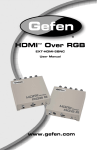
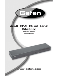
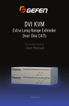
®
EXT-DVI-GI
User Manual
ASKING FOR ASSISTANCE
Technical Support:
Telephone
Fax
(818) 772-9100
(800) 545-6900
(818) 772-9120
Technical Support Hours:
8:00 AM to 5:00 PM Monday through Friday, Pacific Time
Write To:
Gefen, LLC.
c/o Customer Service
20600 Nordhoff St
Chatsworth, CA 91311
www.gefen.com
[email protected]
Notice
Gefen, LLC reserves the right to make changes in the hardware, packaging, and
any accompanying documentation without prior written notice.
DVI Galvanic Isolator is a trademark of Gefen, LLC
© 2012 Gefen, LLC. All rights reserved.
All trademarks are the property of their respective owners.
Rev A1
CONTENTS
1
Important Safety Precautions
3
Introduction
4
Operational Notes
5
Features
6
Panel Layout
7
Panel Descriptions
8
Connecting the DVI Galvanic Isolator
8
9
9
Wiring Diagram
Using the DVI Galvanic Isolator
Sample Application
10 Surface Mounting Instructions
11 Specifications
12 Warranty
IMPORTANT SAFETY PRECAUTIONS
Wiring and Connections
IMPORTANT: The Grounding Stud must be permanently
connected to protective ground by wiring not less than 16
AWG.
Environmental Conditions for Transportation and Storage
Storage Temperature -20°C ~ 70°C
A relative humidity range of 10% to 90%, noncondensing
An atmospheric pressure range of 50 kPa to 106 kPa
Electromagnetic Interference
Operation is subject to the following two conditions:
1.
This device may not cause harmful interference
2.
This device must accept any interference received including
interference that may cause undesired operation
The Gefen EXT-DVI-GI cannot be disposed of in the general trash.
Please contact your solid waste local authority.
1
SAFETY PRECAUTIONS
Read this User Manual before operating the DVI Galvanic Isolator.
•
Cleaning
Unplug this product from main DVI source and DVI sink before cleaning.
Do not use liquid or aerosol cleaners. Use a damp cloth for cleaning.
•
Cables
Use only cables supplied by Gefen.
•
Water and Moisture
Do not use this product near water or in wet environment.
•
Heat
The product should be situated away from heat sources such as
radiators, heat registers, stoves, or other products that generate heat.
•
Power Sources
This product should be operated only from the type of power source
indicated on the marking label.
•
Servicing
Do not attempt to service this product yourself as opening or removing
covers may expose you to dangerous voltage or other hazards. Refer all
servicing to qualified service personnel. The product must be used with
AC/DC power adaptor supplied by manufacturer.
2
INTRODUCTION
Congratulations on your purchase of the DVI Galvanic Isolator. Your complete
satisfaction is very important to us.
About Gefen
We specialize in total integration for your home theater, while also focusing on
going above and beyond customer expectations to ensure you get the most from
your hardware. We invite you to explore our distinct product line. Please visit
http://www.gefen.com for the latest offerings in High-Definition signal solutions
or call us between the hours of 8:00 am and 5:00 pm Monday-Friday, Pacific
Standard Time for assistance with your A/V needs. We’ll be happy to assist you.
The Gefen DVI Galvanic Isolator
The Gefen DVI Galvanic Isolator is used in mission-critical applications where
galvanic isolation between the connected DVI (source and display) is required to
eliminate the potential for ground loops and provide de-coupling between various
devices used in a High-Definition video system. This is a safety requirement in
applications such as medical imaging systems where certain components of the
system (such as endoscopy cameras) come in direct contact with the patient and
the medical operator.
How It Works
Using the included DVI cable, connect the imaging source, such as a camera,
to the DVI input of the DVI Galvanic Isolator. Connect the output of the DVI
Galvanic Isolator to the next DVI component in the system such as a video
scaler or a high resolution display. Connect the supplied 5V DC power supply to
the locking connector on the DVI Galvanic Isolator and to an available electrical
outlet. Power up the systems after all the cables and power connections are
made.
3
OPERATIONAL NOTES
READ THESE NOTES BEFORE INSTALLING OR
OPERATING THE DVI GALVANIC ISOLATOR
•
Operation is subject to the following conditions:
1.
This device may not cause harmful interference.
2.
This device must accept any interference received including
interference that may cause undesired operation.
•
This product is not designed for marine use. Do not use this product near
water or in a wet environment.
•
Always connect a bonding wire between an approved safety ground and the
grounding screw on the chassis.
IMPORTANT: This product cannot be disposed of in the general
trash. Please contact your solid waste local authority.
4
FEATURES
Features
•
Provides up to 5kV full galvanic isolation between DVI components
•
Supports resolutions up to 1920 x 1200 (WUXGA)
•
EDID pass-through
•
HPD pass-through
•
Isolation between the input and out DVI
•
Grounding Terminal
•
Locking power supply connector
Package Includes
(1) DVI Galvanic Isolator
(1) 6 ft. DVI cable (M-M)
(1) 5V DC locking power supply
(1) Set of Mounting Plates
(1) Quick Start Guide
5
PANEL LAYOUT
Front
1
Top
Back
2
3
4
6
5
PANEL DESCRIPTIONS
1
DVI In
Connect the included DVI cable between the imaging source (such as an
endoscopy camera) and the DVI In port.
2
5V DC
Connect the included 5V DC power supply to this connector. Only use the
power supply shipped with this unit.
3
Power
This LED will glow bright blue once the included 5V DC power supply has been
properly connected between the locking power receptacle and an available
electrical outlet.
4
DVI Out
Connect a DVI cable between this port and a video scaler or a high-resolution
display.
5
Grounding Stud
The Grounding Stud must be permanently connected to protective ground by
wiring not less than 16 AWG.
7
CONNECTING THE DVI GALVANIC ISOLATOR
How to Connect the DVI Galvanic Isolator
1.
Connect the included DVI cable from the imaging source (e.g. camera) to the
r
DVI In port on the DVI Galvanic Isolator.
2.
Connect a DVI cable from the DVI Out port on the DVI Galvanic Isolatorr to a
video scaler or high-resolution display.
3.
Connect a bonding wire from the Grounding Terminal to an approved safety
ground.
4.
Connect the included locking power supply to the DVI Galvanic Isolatorr and
connect the AC power to an available electrical outlet.
Wiring Diagram for the DVI Galvanic Isolator
DVI CABLE
Laparoscopic Camera
DVI Galvanic Isolator
Monitor / Display
EXT-DVI-GI
8
USING THE DVI GALVANIC ISOLATOR
Sample Application
The illustration below depicts a medical application using a galvanic isolator.
The DVI Galvanic Isolatorr provides an electrical barrier between low voltage
electronics and an externally-exposed imaging system.
Unwanted contact with sources of high voltage can cause damage to the low
voltage electronics within a camera (or other imaging source). The DVI Galvanic
Isolatorr protects both the imaging source and patient from misdirected electrical
voltages outside of the working zone, indicated by the red plane.
Imaging source
(endoscopy camera)
DVI cable
(input)
DVI Galvanic
Isolator
Isolated
working zone
Earth-ground
(from grounding
terminal)
DVI cable
(output)
High-resolution
imaging system
9
SURFACE MOUNTING INSTRUCTIONS
The Gefen DVI Galvanic Isolator can be mounted on any flat surface using wood
/ drywall screws as shown in the diagram above. There should be an inch or two
of clearance between the edges of the unit and any walls or vertical surfaces to
allow for enough clearance for connection and disconnection of DVI cables.
For installation on a drywall surface, use a #6 drywall screw. When installing, it is
recommended to use the center hole on a stud.
10
SPECIFICATIONS
Maximum Pixel Clock .............................................................................. 165 MHz
Input Connector .............................................. (1) DVI 29-pin, female (digital only)
Output Connector ........................................... (1) DVI 29-pin, female (digital only)
Power Supply ........................................................... (1) 5V DC, locking connector
Storage Temperature.........................................................................-20°C to 70°C
Relative Humidity.....................................................10% to 90% (non-condensing)
Atmospheric Pressure.................................................................50 kPa to 106kPa
Dimensions (W x H x D) .................... 5.8” x 1.2” x 3.5” (146mm x 30mm x 85mm)
Shipping Weight ................................................................................ 2 lbs (0.9 kg)
11
WARRANTY
Gefen warrants the equipment it manufactures to be free from defects in material
and workmanship.
If equipment fails because of such defects and Gefen is notified within two (2)
years from the date of shipment, Gefen will, at its option, repair or replace the
equipment, provided that the equipment has not been subjected to mechanical,
electrical, or other abuse or modifications. Equipment that fails under conditions
other than those covered will be repaired at the current price of parts and labor in
effect at the time of repair. Such repairs are warranted for ninety (90) days from
the day of reshipment to the Buyer.
This warranty is in lieu of all other warranties expressed or implied, including
without limitation, any implied warranty or merchantability or fitness for any
particular purpose, all of which are expressly disclaimed.
1.
Proof of sale may be required in order to claim warranty.
2.
Customers outside the US are responsible for shipping charges to and from
Gefen.
3.
Copper cables are limited to a 30 day warranty and cables must be in their
original condition.
The information in this manual has been carefully checked and is believed to
be accurate. However, Gefen assumes no responsibility for any inaccuracies
that may be contained in this manual. In no event will Gefen be liable for
direct, indirect, special, incidental, or consequential damages resulting from
any defect or omission in this manual, even if advised of the possibility of such
damages. The technical information contained herein regarding the features and
specifications is subject to change without notice.
For the latest warranty coverage information, refer to the Warranty and Return
Policy under the Support section of the Gefen Web site at www.gefen.com.
PRODUCT REGISTRATION
Please register your product online by visiting the Register Product page
under the Support section of the Gefen Web site.
12
Rev A1
20600 Nordhoff St., Chatsworth CA 91311
1-800-545-6900
818-772-9100
www.gefen.com
Pb
fax: 818-772-9120
[email protected]