1
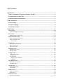
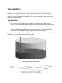
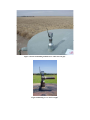
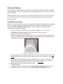
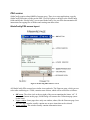
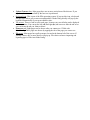
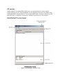
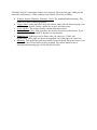
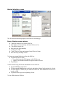
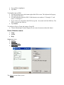
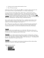
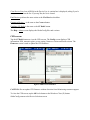
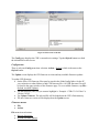
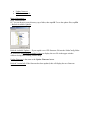
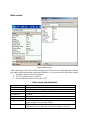
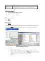
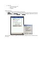
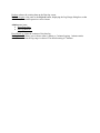
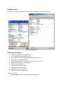
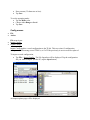
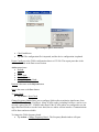
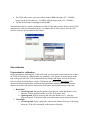
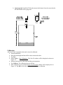
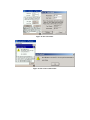
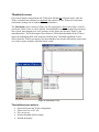
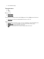
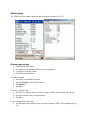
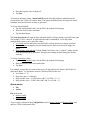
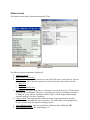
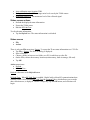
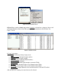
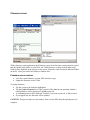
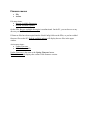
Ferguson Beauregard iMonitoring iNodes
TLMe
Ultrasonic Tank Level Monitor
User Installation and Operating Manual
100387-22, Rev. (-)
3/27/2007
Table of Contents
Introduction.................................................................................................................................... 4
What is an iMonitoring Tank Level Monitor (TLMe)? ..................................................................... 4
Principal features of the TLMe ............................................................................................................. 4
Additional support documentation ....................................................................................................... 5
TLMe installation........................................................................................................................... 6
Tank mounting........................................................................................................................................ 6
Solar panel lighting................................................................................................................................. 8
Installation procedure ............................................................................................................................ 8
iNodeConfig ................................................................................................................................... 9
PDA version .......................................................................................................................................... 10
iNodeConfig PDA screen layout........................................................................................................................10
PC version ............................................................................................................................................. 12
iNodeConfig PC screen layout...........................................................................................................................12
Device Selection screen......................................................................................................................... 14
Device Selection screen actions .........................................................................................................................14
Device Selection menus .....................................................................................................................................15
CFR screens ..................................................................................................................................................17
Data screen ............................................................................................................................................ 20
Data values and definitions ................................................................................................................................20
Data screen actions.............................................................................................................................................21
Data screen menus .............................................................................................................................................21
Data log screen. ..................................................................................................................................... 25
Data log screen actions.......................................................................................................................................25
Data log menus...................................................................................................................................................26
Config screen......................................................................................................................................... 28
Config screen actions .........................................................................................................................................28
Config menus .....................................................................................................................................................29
Site calibration ...................................................................................................................................................31
Preparation for calibration.............................................................................................................................31
Calibration.....................................................................................................................................................32
Thresholds screen ................................................................................................................................. 34
Thresholds screen actions ..................................................................................................................................34
Thresholds menus ..............................................................................................................................................35
Alarms page .......................................................................................................................................... 36
Alarms page actions ...........................................................................................................................................36
Alarm menus ......................................................................................................................................................37
Status screen.......................................................................................................................................... 39
Status screen actions ..........................................................................................................................................40
Status menus ......................................................................................................................................................40
Firmware screen ................................................................................................................................... 43
Firmware screen actions.....................................................................................................................................43
Firmware menus.................................................................................................................................................44
TLMe Specifications .................................................................................................................... 45
Introduction
What is an iMonitoring Tank Level Monitor (TLMe)?
Figure 1. The TLMe.
The Ferguson Beauregard Tank Level Monitor (TLMe) is used to measure fluid levels
ultrasonically in tanks and silos. Part of the iNodes suite of wireless sensors, it delivers data
remotely over the Internet or locally to any Compact Flash Radio-enabled computer. The TLMe
eliminates the need for daily tank gauging, providing 24-hour production data with consistent
daily data collection times.
Principal features of the TLMe
•
•
•
•
•
•
Eliminates the need for manual daily tank gauging.
Uses advanced ultrasonic sensing technology.
Reports fluid depth or distance to fluid.
Collects daily production data consistently.
Provides consistent 24-hour production data with programmable data collection times.
Includes power supply, data storage, processing and bidirectional radio communications
in a small, integrated package.
•
•
•
•
•
•
•
Certified intrinsically safe.
Communicates with any Compact Flash Radio-enabled PC, including pen tablet PCs,
PDAs and our Concentration & Communications Unit.
Solar powered with backup battery.
Rugged IP-65 rated enclosure.
Field configurable and upgradeable.
Low cost.
Basic alarm capabilities (alarm service optional).
Additional support documentation
More detail on mounting options, calibration and other features can be found in the Ferguson
Beauregard Installers’ Guide, which presents in-depth information on all iNode devices. The
Installers’ Guide can be downloaded from the FB Customer Support website
(http://sw.fergusonbeauregard.com) in the iNode Products section.
TLMe installation
The TLMe measures tank fluid levels ultrasonically, using a technique similar to radar. It
transmits a pulse which reflects off the liquid surface and returns to the TLMe. The TLMe
measures the pulse “flight time”, then compensates for the effect of temperature on the speed of
sound. It is important to mount and install the TLMe correctly to obtain the most accurate and
reliable level measurements.
Tank mounting
1. For best accuracy the TLMe must be mounted at right angles to the fluid surface + 2
degrees. This maximizes the signal strength of the reflected signal for best measurement
accuracy.
2. At 260 inches (about 21 feet), there must be at least 15 inches of clearance from the
center of the beam to any obstacles such as internal tank braces. This minimizes any
reflections or weakening of the signal, improving measurement accuracy.
Figure 1 below shows a properly installed TLMe. Figure 2 and Figure 3 show two TLMe field
installations. Figure 2 is the preferred mounting method.
Figure 2. Proper TLMe mounting angle.
Figure 3. Preferred mounting method on a 2" NPT non-vent pipe.
Figure 4 Mounting on a 2" NPT vent pipe.
Solar panel lighting
The TLMe power supply contains a solar panel, high-capacity rechargeable battery, charging
circuit and regulator. When fully charged the TLMe will typically operate for at least two weeks
without sunlight.
Manmade lighting such as fluorescent or incandescent lights will not generate sufficient power
for continuous operation. The TLMe must be mounted so that the solar panel is exposed to
ambient sunlight.
Installation procedure
When the TLMe is installed, it must be provisioned in its intended configuration. The installation
must comply with all regulatory and safety requirements. With the exception of those items
listed in the TLMe installation instructions, the TLMe is shipped with factory default
calibration and configuration settings.
1. If you are unfamiliar with iNodeConfig or TLMe installation, review the Site
Calibration and iNodeConfig sections of this manual before beginning.
2. Remove the TLMe from its packing box.
3. Remove the Phillips head reset button access screw on the bottom of the unit (Figure 5).
Using a non-metallic tool, press and hold the reset button briefly to bring the unit out of
sleep mode, then replace the screw and lightly tighten it.
Figure 5. Reset button access screw.
4. Drop a gauging tape into the pipe fitting where the TLMe will be attached. Measure and
record the distance from the bottom of the tank to the top of the fitting. This is the tank
height.
5. Screw the TLMe temporarily into the pipe fitting (Figure 2 or Figure 3). Mark the last
exposed thread on the TLMe bushing and remove the unit. Measure and record the
distance from the thread to the sensor face. This is the head offset.
6. Permanently mount the TLMe to the tank fitting.
7. Install the antenna.
8. Configure the TLMe as instructed in the iNodeConfig Configuration screen section.
9. Calibrate the TLMe as instructed in the iNodeConfig Site Calibration section.
iNodeConfig
Local communication with iNodes is necessary for setup and maintenance. The same radio
system used to collect data from iNodes by the CCU also supports local communications. The
local communications software, called iNodeConfig, allows you to configure iNodes, set
controls and view or save data and configurations.
There are two versions of iNodeConfig: iNodeConfig-PDA, which runs on PDAs with the
Windows CE operating system, and iNodeConfig-PC, which runs on laptops and PCs with
Windows 2000, NT or XP. An iMonitoring Compact Flash Radio card (CFR) is required. The
two versions are as similar as possible to minimize confusion when switching between a PDA
and a laptop.
The following sections start with the leftmost user screen and move to the right, one screen at a
time. Each user screen shown on the iNodeConfig screen toolbar is denoted by bold type, e.g.
“Data screen”. Configuration or selection items within each screen are denoted by bold type, e.g.
“Configure”.
In these sections you will often be be instructed to “tap” a button or location on the screen. On
the PDA, this means tapping the button or location with the PDA stylus. On PCs, this means
moving the cursor over the button or location, then tapping on a mouse pad, or clicking with the
left mouse button.
Whenever possible, iNodeConfig PDA and PC screen figures are shown side by side so that you
can see the similarities and differences between them. In larger screens, the PDA screen are
shown first and the PC screen are shown second.
The main differences between iNodeConfig for the PC and PDA are:
• The PDA version uses the Windows CE standard tools and features, particularly the
keyboard icon and OK button at the top right of the screen. The PC version uses the
Windows standard tools: Minimize – Maximize – Close buttons at the top right of the
screen, sizeable windows, etc.
• The PC version has no keyboard icon.
• The PDA page tabs run across the bottom of the screen. The PC page tabs run across the
top of the screen.
PDA version
iNodeConfig requires about 800KB of storage space. There is no setup application; copy the
iNodeConfig fileset into a folder on the PDA. Use File Explorer to browse to the iNodeConfig
folder and tap the “iNodeConfig” icon to start iNodeConfig. See your PDA documentation for
instructions on copying files to folders and creating start menu icons.
iNodeConfig PDA screen layout
Figure 6. iNodeConfig-PDA firmware screen.
All iNodeConfig-PDA screens have similar views and tools. The Firmware page, which you can
select after connecting to a TLMe, contains most of them, which will be referred to as follows:
•
•
•
OK button: The white circle at the top right of the screen containing the letters “ok”. If
you tap this button on this page, iNodeConfig will return to the Connection page (more
on this later).
Upper window: Some pages have only one window; others, like the Firmware page, have
two. The upper window usually contains one or more items that can be selected.
Lower window: This window usually contains information items.
•
•
•
•
•
Update Firmware box: Most pages have one or more action boxes like this one. If you
tap a box, the action described by the box text is performed.
Keyboard icon: This is part of the PDA operating system. If you tap this icon, a keyboard
will pop up to allow you to enter text and numbers. iNodeConfig usually will pop up the
keyboard automatically if you tap an editable value.
Tab arrows: There is a tab to select each page. In most cases, not all tabs can be displayed
at the same time. You can tap the left (◄) and right (►) tab arrows to slide the tab set so
you can locate the tab you want to choose.
Firmware tab: Eight pages can be chosen after you connect to a TLMe with
iNodeConfig. These pages are chosen by tapping the tab of the page you want to see.
File menu: Most pages have pull-up menus, located at the bottom left of the screen. If
you tap a menu, one or more choices will pop up. File choices relate to importing and
exporting types of files into iNodeConfig.
PC version
iNodeConfig-PC uses about 6MB of disk space. A setup application is used to install
iNodeConfig on your PC. After installation, use File Explorer to browse to the iNodeConfig
folder and tap the “iNodeConfig.exe” icon to start iNodeConfig. (You may want to copy and
paste the icon as a shortcut to your laptop’s desktop for quick access to the program.)
iNodeConfig PC screen layout
Figure 7. iNodeConfig-PC firmware screen.
All iNodeConfig PC screens have similar views and tools. The Firmware page, which you can
select after connecting to a TLMe, contains most of them, referred to as follows:
•
•
•
•
•
•
Windows buttons (Minimize, Maximize, Close): The standard Windows buttons. They
behave as in other Windows programs.
Upper window: Some pages have only one window; others, like the Firmware page, have
two. The upper window usually contains one or more selectable items.
Lower window: This window usually contains information items.
Update Firmware box: Most pages have one or more action boxes like this one. If you
tap a box, the action described by the box text is performed.
Firmware tab: Eight pages can be chosen after you connect to a TLMe with
iNodeConfig. These pages are chosen by tapping the tab of the page you want to see.
File menu: Most pages have pull-down menus, located at the top left of the screen. If you
tap a menu, one or more choices will be presented. File choices mainly relate to
importing and exporting types of files into iNodeConfig.
Device Selection screen
The first screen iNodeConfig displays is the Device Selection page.
Device Selection screen actions
•
•
•
•
•
•
•
Choose an iNode device from the ESN list.
Find iNodes and automatically add their ESNs to the list.
Clear ESNs from the list.
Enter an iNode ESN manually.
Configure the CFR.
Create a Device Group and assign a Group ID to the Group.
Enter the Setup and Help screens.
To choose an existing iNode device from the ESN list:
• Tap the ESN for the iNode.
o If you double-tap, the ESN appears in the ESN box, or
o Tap the > box and the selected ESN appears in the ESN box.
• Tap Connect.
To make iNodeConfig find iNodes and add them to the ESN list:
• Tap the Find Devices checkbox.
• The bar beneath Find Devices scrolls back and forth as iNodeConfig searches for iNodes.
• As iNode ESNs are found, they are added to the ESN list. Each added ESN will have an *
beside its ESN.
• Tap the checkbox again to stop finding iNodes.
To clear ESNs from the ESN list:
•
•
Tap an ESN to highlight it.
Tap Clear.
To manually enter an ESN:
• Tap the Keyboard icon at the bottom right of the PDA screen. The keyboard will pop up.
• Tap inside the ESN box.
• Use the keyboard to enter the ESN. Valid characters are numbers “0” through “9”, and
letters “a” through “f”.
• If you want to save the ESN in the ESN list, tap the < box to the left of the ESN box. The
ESN is copied to the ESN list.
• Tap Connect.
To configure a Device Group and assign a Group ID:
• Contact iMonitoring Customer Support if you want to learn more about this feature.
Device Selection menus
•
•
•
Setup.
Action.
Help.
Setup menu items:
• Options.
• Group IDs.
• Admin Privileges.
• Demo Mode.
The Options screen allows you to:
•
•
Set behavior with contention and the number of retries.
Show CFR status messages.
Change these settings as needed, then tap the OK box to enable the changes and return to the
Device Selection screen, or tap the Cancel button to exit without making changes.
Contention takes place when another iNode, iNodeConfig or a SCADA radio system is
transmitting as you try to communicate with a device - the signals interfere with each other.
iNodeConfig will detect contention, display a Contention error and stop transmitting. If Ignore
Contention is checked, iNodeConfig will continue to transmit even if there is contention and no
error will be displayed. This is usually an undesirable setting, since it allows you to interfere with
other device communications. The default setting is disabled (unchecked).
Retries sets the number of times iNodeConfig will try to establish communications with an
iNode before quitting. In situations where there is more interference, more retries may be
needed. You can choose 0 through 10 retries (default = 3).
Show CFR status messages allows you to watch the communications progress and messages
between a CFR and an iNode. Expert users enable status messages when troubleshooting
communications problems. Leave this feature disabled unless instructed by iMonitoring.
Group IDs
Groups are used to prevent unauthorized access to iNode data. This feature is risky, as it is
possible to lock users out of devices if the group code is lost or forgotten. Contact iMonitoring
for instructions on the configuration and use of this feature.
User Levels
Three user levels are defined in iNodeConfig: Pumper, Installer and Administrator. A Pumper
can view data but not make configuration changes. An Installer can view data and fully configure
the iNode. The Administrator can change an iNode’s ESN, shut it down, etc. The default level is
Installer. Administrator level requires a password.
Demo Mode
Demo mode allows you to simulate viewing data and configuring an iNode without making
connection to a real device. This option is used in training.
Action menu item selections:
• Clear Device List
• Find Devices
• Connect to Device...
• Configure CF Radio
Clear Device List clears all ESNs in the Device List. A caution box is displayed, asking if you’re
sure you want to clear the list. If you tap Yes, the list is cleared.
Find Devices performs the same action as the Find Devices checkbox.
Connect to Device ... is the same as the Connect button.
Configure CF Radio is the same as the CF Radio button.
The Help - About screen displays the iNodeConfig files and versions.
CFR screens
Tap the CF Radio button to view the CFR screens. The Config screen displays CFR
information: ESN, transmit cypher, power setting, firmware version and board revision. The
Firmware screen is used to update the CFR firmware.
Figure 8. CFR screens on the PDA.
CAUTION: Do not update CFR firmware without direction from iMonitoring customer support.
To close the CFR screen, tap the OK circle button or the Windows Close (X) button.
iNodeConfig returns to the Device Selection screen.
Figure 9. CFR screens on the PC.
The Config page displays the CFR’s current device settings. Tap the Refresh button to refresh
the information on this screen.
Config menus
There is only one Config menu item selection: Action > Refresh, which is the same as the
Refresh button.
The Update screen displays the CFR firmware revision and any available firmware updates.
To update CFR firmware:
• On the PDA, CFR firmware files must be stored in the iNodeConfig folder. On the PC,
you can browse to other folders to find CFR firmware files. All CFR firmware files will
be listed in the upper window of the Firmware page. To see available firmware, tap File >
Refresh Available Updates.
• Tap the firmware (.hex) file you want to highlight it. Example: “CFRv3 3.03.02.hex” is
Version 3.03.02.
• Tap Update Firmware. The selected file will be loaded into the CFR’s flash memory.
• The new firmware version will be displayed on the Update screen.
Firmware menus
•
•
File.
Action.
File menu item selections:
• Browse directories.
• Refresh available updates.
•
•
Update firmware.
Refresh version info.
Browse Directories ...
PDA: Nonfunctional.
PC: You can browse to any directory, tap a folder, then tap OK. To see the update files, tap File
> Refresh Available Updates.
Refresh Available Updates ... If you copied a new CFR firmware file into the iNodeConfig folder
on your PDA, tap Refresh Available Updates to display the new file in the upper window
without closing and restarting iNodeConfig.
Update Firmware is the same as the Update Firmware button.
Refresh Version Info. If the firmware has been updated, this will display the new firmware
version.
Data screen
Figure 10. Data screen.
After connecting to the TLMe, iNodeConfig displays the Data screen, containing data related to
tank liquid depth and important operating information. You can choose from three data formats:
• Transducer data (the most current data),
• RTU data (the data sent to an RTU),
• SatCom data (the last data sent to the iCCU).
Data values and definitions
Item
TLMe ESN
Level
Range
RESERVED
Temperature
Energy level
RSSI margin (dB)
Device status
Definition
Electronic Serial Number (ESN) of the TLMe
The fluid depth.
The distance from the TLMe to the fluid surface.
Not used.
The temperature at the TLMe head.
The charge in the battery in percent.
The Received Signal Strength Indicator value, a measure of the
signal strength received by the TLMe.
Indicates alarm conditions. If an alarm is present, a code and a brief
fault description are displayed, otherwise it displays “Normal”.
Version
Drop in top level,
Drop time span
The TLMe firmware version.
If the level drop alarm is enabled, these will display the level drop
in feet and inches, and the drop time. See the Alarms section.
Data screen actions
•
•
•
View and refresh the current TLMe data.
Export (save) the data to a file.
Run a data loop test.
Data screen menus
•
•
File.
Action.
File menu item.
• Export...
To export the data displayed on the TLMe Data screen to a Comma Separated Variable (CSV)
file, tap File > Export... iNodeConfig will display the Save As screens, shown in Figure 11.
Figure 11. File Export, Save As screens.
•
On the PDA,
o Enter a filename.
o Choose a folder. Tap the ▼ arrow beside the Folder box to list all folders.
o Choose a location. Tap the ▼ arrow beside the Location box for a list of memory
locations: Main Memory, Built-In Storage, or SD Card. (The SD card is the most
reliable, as it does not need a battery to retain its memory.)
o Tap OK.
•
On the PC,
o Type a name for the file.
o Browse to a folder.
o Tap Save.
Action menu items.
• Refresh. Refreshes the data displayed on the screen.
• Data loop... When Data Loop is enabled, iNodeConfig will periodically collect data from
the TLMe. After selecting Data Loop, the Frequency dialog box, which allows you to set
the data collection rate, is displayed:
After choosing a Frequency, tap OK. The collected data is displayed, most recent data at the top
of the page.
Figure 12. Data loop screens.
Data Loop records:
• Time of collection
• Level
• Range
• Temperature
• Energy level
• RSSI margin
• Device status
• Version
• Drop in level
• Drop time span
To save the data, you must enable data logging. NOTE: Any data displayed before data logging
is started cannot be saved later. See File > Log Data below.
Data Loop menu selections
•
•
File.
Setup.
File menu item.
• Log Data...
Log Data allows you to save Data Loop data to a CSV file. If you select this feature, the Save As
dialog is displayed. (This is not the same as the Data Log screen, explained in the next section.)
To log data,
• Enter a file name.
• Choose a folder.
• Tap OK or Save.
PDAs cannot display CSV files directly. You must first move it to a laptop or desktop PC with
ActiveSync, then open it with a spreadsheet program. Logging will continue until you exit the
Data Loop page (tap OK). The PC can display the file contents if it has a spreadsheet program.
Setup menu item:
• Options redisplays the Frequency dialog.
Data log screen.
The TLMe keeps a data log for later review. This log can be downloaded and saved from the
Data log screen.
Figure 13. Data log.
Data log screen actions
•
•
•
Set the log range.
Download the data log.
Save the data log.
When the Data log screen tab is tapped, the Log Range dialog box opens, shown in Figure 14.
By default, the Start Date/Time and End Date/Times are set to the beginning and ending times in
the log. Frequency sets the interval between downloaded log entries: Every 5 minutes, Every 15
minutes, Every Hour, Every 6 Hours, Every 12 Hours, and Every Day.
Figure 14. Data log range screens.
To download the data log,
• Choose a Start Date/Time. (A new date/time must be later than the default and earlier
than the End Date/Time.)
• Choose an End Date/Time. (A new date/time must be earlier than the default and later
than the Start Date/Time.)
• Choose an entry Frequency.
• Tap OK.
A downloaded log is displayed similar to those shown in Figure 13.
The data log contains the following data:
• Entry date and time.
• Range or Level, depending on the operating mode.
• Temperature.
• Energy level.
• Device status.
Data log menus
•
•
•
File
Action.
Admin. (Requires Administrator login.)
File menu items:
• Export...
The data log can be saved to a CSV file for later review. See the Data screen, File > Export. The
save process and screens are the same.
Action menu items:
• Redraw.
• Refresh/Acquire.
Redraw redraws the existing data on the Data log screen.
Refresh/Acquire is the same as the Refresh button, displaying the Log Range dialog box so that
other dates, times and frequencies can be chosen.
Admin menu items:
• Reset Data Log...
• Set Log Interval...
Reset Data Log clears the contents of the data log.
Set Log Interval allows you to choose either 1 minute or 5 minute logging. 1 minute entries
record more data but the log range is reduced. The default setting is 5 minutes.
Config screen.
Most TLMe configuration settings are located on the Config screen, shown in Figure 15.
Figure 15. Config screens.
Config screen actions
•
•
•
•
•
•
•
•
•
•
•
Name the TLMe for easier identification.
Set the operating mode (Range or Level).
In Level mode, set the Tank height and Head offset values.
Set the Filter size and Hysteresis.
Synchronize the real-time clock (RTC) to the PDA or PC clock.
Import and export device configuration.
Perform a site calibration.
Change the RF frequency band.
Change the ESN (admin only).
Change the cypher (admin only).
Shut the TLMe down (admin only).
To name the TLMe:
• Tap the Name value. On the PDA, the keyboard pops up.
•
•
Enter a name (32 characters or less).
Tap Save.
To set the operating mode:
• Tap the Mode value.
• Choose either Range or Level.
• Tap Save.
Config menus
•
•
File
Action.
•
•
File menu items:
Import Config...
Export Config...
Import Config applies a saved configuration to the TLMe. This saves time if configuration
settings are similar among several TLMe’s, or if a TLMe previously in service must be replaced.
To import a saved configuration,
• Tap File > Import Config... The File Open box will be displayed. Tap the configuration
file you want to import. (On the PC, tap the Open button.)
An import options page will be displayed.
Figure 16. Import options selection boxes.
•
•
Check both boxes.
Tap OK. The configuration file is imported, and the device configuration is updated.
Export Config saves the TLMe configuration data to a CSV file. The export procedure is the
same as described in the Data screen section.
Action menu items:
• Refresh.
• Save.
• Sync Clock.
• Site Calibration...
• Change Frequency Band...
Refresh is the same as the Refresh button.
Save is the same as the Save button.
To Sync Clock:
• Tap Action > Sync Clock.
Change Frequency Band allows you to configure iNode radios to minimize interference from
some SCADA radios (e.g. FreeWave). Many SCADA radios, including FreeWave, can be set to
use only a part of the 902 – 928MHz radio band. If the SCADA radios are configured to use the
upper band and iNodes to use the lower band, the two radios will not interfere. Communications
will be faster and more reliable.
To change the TLMe frequency band:
• Tap Action > Change Frequency Band... The Frequency Band window will open.
•
•
The TLMe radio can be set to one of three modes: Wide (the entire 902 – 928MHz
range), A (the lower band, 902 – 916MHz) or B (the upper band, 914 – 928MHz).
Tap the desired mode to highlight it and tap OK.
Note that this requires a similar configuration of the SCADA radio system. Refer to the SCADA
manufacturer’s data for information on how to configure the SCADA system. Also the CFR
must be set to use the same band as the iNodes.
Figure 17. Frequency band settings.
Site calibration
Preparation for calibration.
Before permanently mounting the TLMe to the tank, you must make two measurements so that
the TLM can be properly calibrated after it is installed: (1) the distance from the bottom of the
tank to the point where the TLM is threaded into the fitting (tank depth), and (2) the distance
between where the fitting mates with the TLM thread and sensor head (head offset). The
automated calibration procedure performed after installation subtracts head offset from tank
depth and calculates the distance between the TLM sensor head and the bottom of the tank.
1. Head offset.
a. Closed top tank. Measure the distance from the last visible thread that is seen
when the TLM is installed and the tip of the TLM sensor head.
b. Open top tank. With an open top tank enter this distance as ‘0’, since the
distance from the TLM sensor head to the tank bottom can be measured directly.
2. Tank depth.
a. Closed top tank. Using a gauge line, measure the distance from top of the fitting
where the TLM will be mounted, to the bottom of the tank.
b. Open top tank. Install the TLM and measure the distance from the sensor head to
the tank bottom with a gauge line.
Calibration
After the TLMe is mounted to the tank, it must be calibrated.
• Select Level Mode.
• Enter the tank height and head offset values measured earlier.
• Tap Save.
• Select Action > Site Calibration... The Site Cal window will be displayed as shown in
Figure 18.
• Measure and enter the fluid depth and the gas temperature.
• Tap Calibrate. The calibration process will run.
• If the calibration is successful, the Site Cal Successful window will be displayed as in
Figure 19. Tap OK to close the window and complete the calibration.
Figure 18. Site Cal window.
Figure 19. Site cal successful window.
Thresholds screen
For accurate distance measurement, the TLMe must find the first reflected signal. After the
TLMe is installed and calibrated, its threshold (the signal levels the TLMe uses for distance
calculations) settings can be adjusted for best performance.
The Thresholds screen is shown in Figure 20. If a signal pulse is above the red line, it will be
used by the TLMe. If not, it will be ignored. The threshold levels can be changed by touching a
line or point, then dragging it to a new position. (In the figure, the first blue “signal” is the
transmitted pulse. The second signal is the reflection.) The default thresholds set the TLMe to
ignore the transmitted pulse while using the reflected pulse. Threshold adjustment is more
critical when the TLMe is measuring very short distances between the fluid and the sensor head,
or it needs to ignore multiple reflections inside a tank.
Figure 20. Thresholds screens.
Thresholds screen actions
•
•
•
•
•
Import and export the TLMe configuration.
Export a trace to a CSV file.
Get a new trace.
Restore threshold default settings.
Refresh the display.
•
Save threshold settings.
Thresholds menus
•
•
File.
Action.
File menu items:
• Import Config...
• Export Config...
These selections are identical to those on the Config screen. See the Config section for their use.
•
Export trace saves the trace and threshold data values to a CSV file.
Action menu items:
• Get trace causes the TLMe to acquire a new trace and display it on the Thresholds screen.
• Restore defaults resets the threshold levels and locations to their default values.
• Refresh refreshes the data displayed on the screen.
• Save saves any threshold level or location changes made on the screen.
Alarms page
The TLMe can detect alarm conditions and send alarm messages to a CCU.
Alarms page actions
•
•
•
•
Enable and disable alarms.
Set alarms for low and high fluid levels or temperatures.
Configure a level drop alarm.
Set the alarm holdoff time.
To enable an alarm:
• All alarms are disabled by default.
• Tap the Disabled value beside an alarm.
• Tap Enabled.
• Tap Save.
To set a level alarm value:
• Tap the level setpoint value you want to change. (PDA: The keyboard will pop up.)
• Enter the setpoint value in feet and inches.
• Tap Save.
To set a temperature alarm value:
• Tap the temperature setpoint value you want to change. (PDA: The keyboard will pop
up.)
•
•
Enter the setpoint value in degrees F.
Tap Save.
To minimize nuisance alarms, Alarm holdoff sets the time that an alarm condition must be
present before the TLMe will send an alarm. The longer the holdoff time, the longer the alarm
condition must persist before an alarm is generated.
To set the Alarm holdoff:
• Tap the Alarm holdoff value. On the PDA, the keyboard will pop up.
• Enter the desired value in minutes.
• Tap the Save button.
The level drop alarm will send an alarm when the tank level drops during a selectable time span
(for example, if oil is “thieved” at night when the tank is unattended). Level drop alarm
configuration requires you to enter four values:
• Level drop (in feet and inches) sets the fluid level drop necessary to trigger an alarm.
• Drop time span (in minutes) sets the maximum time interval necessary to trigger an
alarm.
• Drop window start and end (24 hour format, local time) sets a “window” during which a
level drop alarm can be generated. This prevents sending an alarm during the normal
workday.
To set the Level drop values:
• Tap the Alarm holdoff value. On the PDA, the keyboard will pop up.
• Enter the desired value in feet and inches.
• Tap Save.
For example, assume that you want to detect a level drop and send an alarm if the fluid level
drops more than 1’ in 10 minutes, between 7PM and 5AM. In this case,
• Level drop = 1’ 0”.
• Drop time span = 10 minutes.
• Drop window start = 19 (PM values add 12, so 7PM = 12 + 7).
• Drop window end = 5 (AM values don’t add 12, so 5AM = 5).
Alarm menus
•
•
File.
Action.
File menu items:
• Import Config.
• Export Config.
As previously explained in the Configuration section, Import Config and Export Config load
and save TLMe configuration files.
Action menu items:
• Enable (not functional).
• Refresh.
• Save.
Refresh and Save refresh the Alarms values page and save your changes. They are the same as
the Refresh and Save buttons.
Status screen
The Status screen displays information about the TLMe.
Figure 21. Status screens.
The following status information is displayed:
• Firmware version.
• Board (hardware) revision.
• Self-test codes. When it is powered on or reset, the TLMe runs several self-tests. The test
results display ‘OK’ if the test is passed, or a brief description of the failure if it fails.
o Radio test.
o Clock test.
o FLASH (memory) test.
• Reset source. The typical reset source is ‘Hardware reset pin & power-on’ (The hardware
reset pin is the reset button. There are several other reset sources. If another reset source
is displayed, it may indicate a problem with the TLMe. Consult Ferguson Beauregard
customer support if you have a problem.)
• Charge current. This represents the amount of charge current generated by the solar
panel. In average sunlight this value is typically > 40. If the value is 0 in sunlight, there
may be a failure in the solar panel or charging circuit.
• Auto-calibration status. After a successful site calibration, this will display OK.
• Auto-calibration passes. This should display “5”.
•
•
•
Auto-calibration error location. TBD.
Background noise level. The average noise level seen by the TLMe sensor.
Reflection peak level. The maximum level of the reflected signal.
Status screen actions
•
•
•
Refresh the displayed status information.
Export the TLMe status.
Run the RF Link Test.
To refresh status information:
• Tap the Refresh box. The status information is refreshed.
Status menus
•
•
File.
Action.
There is only one File menu item, Export. To export the TLme status information to a CSV file:
• Tap File > Export. The Save As dialog is displayed.
• Enter a filename.
• Choose a folder (or browse to a folder, on a PC) in which to save the file.
• On the PDA, choose the memory location (main memory, built-in storage, SD card).
• Tap OK.
Action menu items:
• Refresh.
• RF Link Test...
Refresh is the same as the Refresh button.
RF Link Test... When RF Link Test is enabled, iNodeConfig collects RF communications data
from the TLMe. After selecting RF Link Test, the Frequency box, which allows you to set the
data collection rate, is displayed. Choose a Frequency, tap the OK button, and collection will
begin.
Figure 22. Data loop options boxes.
RF Link Test is similar to Data Loop, and the Frequency selection box is identical. However all
collected information relates to the radio system used to communicate with all iNodes. See
Figure 23 below.
Figure 23. RF link test data.
RF Link Test displays:
• Time of collection (24-hour format, local)
• CFR RX Channel (inbound channel number)
• CFR Rssi (inbound signal strength)
• CFR TX Channel (outbound channel number)
• Dev RX Channel (outbound
• Dev Abs RSSI (inbound signal strength, seen on the TLMe)
• Dev thres (noise threshold of the received channel on the TLMe)
• Dev margin (noise margin of the received channel on the TLMe)
• Timing offset (timing alignment value synchronizing the TLMe and CFR radios)
After the link test is running, two menu items can be selected:
•
•
File > Log data. The link test data can be logged to a CSV file. NOTE: Data logging must be
selected after the link test is started. Data displayed on the screen before logging is enabled will
not be saved to the log.
Setup > Options. Displays the Frequency dialog box.
RF Link Test is usually only used by iMonitoring for system troubleshooting.
Firmware screen
TLMe firmware can be updated on the Firmware screen. New firmware versions must be copied
into the iNodeConfig folder on your PDA. All TLMe firmware versions in the iNodeConfig
folder will be displayed in the top box on the screen. Firmware can be located in different folders
on the PC, since you can browse folders to find the files.
Firmware screen actions
•
•
View the current firmware version, ESN and device type.
Update the firmware on the TLMe.
To update firmware,
• Tap the version to be loaded to highlight it.
• Tap the Update Firmware box. If the version is older than the one presently loaded, a
notification box will be displayed. Tap OK to proceed.
• A confirmation box will be displayed. Tap Yes if you want to proceed, or No to cancel.
• If you tapped Yes, the firmware will be updated.
CAUTION: This process takes several minutes. Don’t use the PDA until the upload process is
complete.
Firmware menus
•
•
File.
Action.
File menu items:
• Browse Available Directories.
• Refresh Available Updates.
On the PDA, Browse available directories is nonfunctional. On the PC, you can browse to any
directory on the PC to find firmware files.
If firmware files have been copied into the iNodeConfig folder on the PDA, or you have added
firmware files on the PC, Refresh available updates will display the new files in the upper
window.
Action menu items:
• Update Firmware.
• Refresh Version Info.
Update Firmware is the same as the Update Firmware button.
Refresh Version Info displays the current TLMe firmware version.
TLMe Specifications
Measurement
Fluid level range
Accuracy
18 to 240 inches (1.5 to 20 feet)
+/- 2”
Radio range: Sensor to
CCU
Radio range: Sensor to
CFR-enabled device
Radio technology
Communications protocol
1,500 feet typ. line of sight. > 5000 feet with
optional high gain antenna.
500 feet.
Electrical
Data log
902-928 MHz spread spectrum frequency hopping.
Proprietary iMECH protocol specifically designed
for iNode wireless sensors
Access to sensor data can be restricted by cypher
Internally stored data logs, 30 day length
1/4w solar panel, rechargeable Li-Ion battery and
integrated charger/regulator
Level measurement data logs stored internally
Mounting
3” NPT fitting
Operating temperature
Humidity
-40oC to + 60oC (-40oF to 140oF)
0 to 95% non-condensing
Safety listings
FCC approval
UL and c-UL Class l, Div. l,
Groups C and D (Intrinsically safe)
CFR 47 Part 15
Product life
> 5 years by design
Security
Data logging
Power
Mechanical
Environmental
Certifications
Reliability
The Ferguson Beauregard iNodes suite of products includes:
•
•
•
•
•
•
•
•
Tank Level Monitor (TLM1, TLMe, TLM-3)
Wireless Data Switch (WDS)
Electronic Flow Monitor (EFM)
Compact Flash Radio (CFR)
Wireless Pressure Monitor (WPM)
Concentration & Communications Unit (CCU)
CCU with RTU analog and digital input interface (CCU-RTU)
Wireless Two Pen Pressure Recorder (WPM-2P)
Other Services compatible with our iNodes suite:
FieldDIRECT® is an end-to-end service for collecting and storing production data and
delivering it directly to your desktop via a Web-based interface. It operates seamlessly with our
iNodes intelligent sensors and our handheld data entry system. That gives you data capture
options that are economical even for mature fields with wells producing as little as five BOE per
day.
For more details on iNodes and FieldDIRECT, call 1-903-561-4851, fax (903) 561-6567, visit
our Web site at www.FergusonBeauregard.com/products, or send an e-mail to:
[email protected].