1
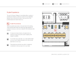
Chapter 1
Getting Acquainted
This chapter describes unpacking the 5 GHz Wireless-N HD Access Point/Bridge WNHDE111, its
key hardware features, and positioning the unit.
This chapter includes the following sections:
•
“Unpacking Your New Wireless-N AccessPoint/Bridge” on page 1-1
•
“Key Hardware Features” on page 1-3
•
“Positioning Your Unit” on page 1-6
Before you begin installing your bridge, check the package contents. Become familiar with the
front and back panels of your bridge—especially the status lights—and the important information
on the bridge label. Then, read the section on positioning your to ensure that you have selected the
best location to install your bridge.
Unpacking Your New Wireless-N AccessPoint/Bridge
Your product package should contain the following items:
•
The bridge
•
A snap-on stand for your bridge
•
An AC power adapter (varies by region)
•
A blue Ethernet cable
•
The Resource CD, which includes:
•
–
The Smart Wizard Installation Assistant
–
A link to the online User Manual
Warranty and Support Information cards
If any of the parts are incorrect, missing, or damaged, contact your NETGEAR dealer. Keep the
carton, including the original packing materials, in case you need to return the product for repair.
1-1
v1.1, May 2008
WNHDE111 5GHz Wireless-N HD Access Point/Bridge User Manual
Prepare for Installation
Carefully peel off the protective film covering both sides of your bridge
Figure 1
Set up your bridge by inserting the tabs of the stand into the slots on its bottom as shown. Then,
remove the protective film covering the status light panel.
Figure 2
Place your bridge in a suitable area for installation (near an AC power outlet and accessible to the
Ethernet cables for your wired connections).
Note: To ensure proper heat dissipation and for bridge stability, it is important that
you connect the stand, place your bridge in an upright position, and do not
block the vent holes at the top.
1-2
Getting Acquainted
v1.1, May 2008
WNHDE111 5GHz Wireless-N HD Access Point/Bridge User Manual
Key Hardware Features
Before you install and connect your bridge, take a moment to become familiar with its front and
back panels—especially the status light and Push N Connect push button on the front panel.
Front Panel
The lights on the front panel indicate the operating status of the bridge.
Illuminated Power LED
On – Amber
The unit is performing the power-on diagnostic tests.
On – Green
The power is on and the router is ready.
Fast blink – Green
A software update is in progress.
Slow blink – Green
There is a problem with the wireless router software.
Off
Power is not being supplied to the unit, the wireless radio is
turned off, or the LED push button switch on the back is off.
Illuminated WPS Push 'N' Connect Button
On – Amber
The unit is performing the power-on diagnostic tests.
On – Green
The wireless range extender has acquired an Internet
address.
Blink – Green
Data is being communicated with the Internet.
Off
Power is not being supplied to the unit, or the LED push button
switch on the back is off.
Figure 1-1
Note: Pressing the LED On/Off button on the back of the unit turns off all the LEDs, including the
these on the front (Power, and WPS), as well as those on the rear (Ethernet status).
Getting Acquainted
1-3
v1.1, May 2008
WNHDE111 5GHz Wireless-N HD Access Point/Bridge User Manual
Back Panel Connectors, Buttons, and Switches
This illustration identifies the connectors and switches on the back of the unit.
Factory Default
Reset Button
Power
Ethernet ports
LED on/off switch
Mode switch
Figure 1-2
Table 1-1. Connectors, Buttons, and Switches
Connector, Button, or Switch
Description
Power connector
Port for connecting the AC power adapter.
Two 10/100 Mbps Ethernet ports
For connecting the unit via Ethernet cables to other equipment like
switches, game consoles, media adapters, print servers, or a router.
Factory default reset button
Restore factory settings button. Use a paper clip to press this button
for about 10 seconds to reset the unit to its factory default settings.
Mode switch settings
• Auto. Auto is the factory default setting. In Auto mode, if it senses it
is connected to a router or gateway, it automatically sets itself to run
as an AP. Otherwise, if connected to any other wired device, it
automatically sets itself to run in Bridge mode.
• AP. When switched to AP (access point) mode, it acts as an access
point. In this mode, connect it to a router. The free Ethernet port can
be used to connect other equipment to your network via an Ethernet
cable.
• Bridge. In Bridge mode, connect devices to it via Ethernet cables
and they will connect to your wireless network. Typically, when a unit
is set to bridge mode, it will be paired with a WNHDE111 working in
AP mode.
LED On/Off button
Press this button to turn off all the LEDs, including the those on the
front (Power, and WPS), as well as those on the rear (Ethernet status).
1-4
Getting Acquainted
v1.1, May 2008
WNHDE111 5GHz Wireless-N HD Access Point/Bridge User Manual
Key Back Panel Label Information
Note: The WNHDE111 comes with a WPA/WPA2 security key enabled by default. This key is
the serial number printed on the label on the back of on the unit. The default wireless
network name (SSID) is NETGEAR-HD.
This illustration identifies key information printed on the back panel label of the unit.
Default Access
Address, User Name
and Password
WPS
Security Pin
1TX18149020CB
Serial number which is also the
default WPA/WPA2 security key
MAC
Address
Figure 1-3
Table 1-2. Product label information
Item
Default Access.
Description
Use this URL, user name and password to log in to the unit.
Note:
Tip:
WPS Security PIN.
During initial setup, the URL will only connect you to the unit
when your computer is attached directly to one of the unit’s
Ethernet ports.
Generally, using the NETGEAR setup wizard will be more
convenient than logging in to the unit with this information.
This PIN is used for devices that require manual entry of the WPS PIN,
or with WPS registrar discovery services, found in Windows Vista for
example.
Getting Acquainted
1-5
v1.1, May 2008
WNHDE111 5GHz Wireless-N HD Access Point/Bridge User Manual
Table 1-2. Product label information
Item
Description
Serial Number which is also
default WPA/WPA2 security
key.
The serial number is also the factory default WPA/WPA2 security key.
This enables easy automated WPS Push 'N' Connect setup.
MAC Address.
The Media Access Control (MAC) address of this unit, which will be
visible in status monitoring screens on the unit or on a router.
Positioning Your Unit
The operating distance or range of your wireless connection can vary significantly depending on
the physical placement of your unit. For example, the thickness and number of walls the wireless
signal must pass through might limit the range.
Note: Failure to follow these guidelines can result in significant performance degradation
or an inability to wirelessly connect to the bridge.
For best results, place your bridge:
•
Near the center of the area where your computers and other devices will operate, preferably
within line of sight to your wireless devices.
•
Accessible to an AC power outlet and near Ethernet cables for wired computers.
•
In an elevated location such as a high shelf, keeping the number of walls and ceilings between
the wireless range extender and your other devices to a minimum.
•
Away from any large metal surfaces, such as a solid metal door or aluminum studs. Large
expanses of other materials such as glass, insulated walls, fish tanks, mirrors, brick, and
concrete can also affect your wireless signal.
•
If placing 2 Wireless-N AccessPoint/Bridges with a direct line of sight between them, do not
place them closer than 15 feet, as the antennas are tuned for this optimum distance. Orient the
2 units with the front panels (the side with the Power light) facing each other.
1-6
Getting Acquainted
v1.1, May 2008