1
Feb. 26, 2004
US 2004/0035973 A1
Winder and is at a 90° angle compared to the axis of the ?rst
pair of slots. One pair of slots has a larger diameter and is
spaced Wider apart. The other pair has a smaller diameter
and is less spaced.
[0018] The Winder is preferably ?tted onto the drill by
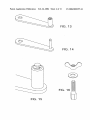
[0033] FIG. 14 is another side vieW of the handle of the
present invention.
[0034] FIG. 15 is yet another side vieW of the handle of
the present invention.
means of its mandrel. Once ?tted onto the drill, the Winder
is pressed onto the ?yreel, in such a manner that the handle
[0035] FIG. 16 is a perspective vieW of another embodi
ment of the present invention shoWing the mandrel of the
and the counterweight Which equip most ?yreels on the
market are lodged in the slots of the Winder. The various
diameters and spacing of the slots match the siZe of about
80% of all ?yreels commonly found in the World. The
Winder is preferably centered on the ?yreel. Circular ribbing
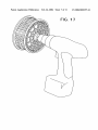
[0036] FIG. 17 is a perspective vieW of another embodi
ment of the present invention shoWing a drill interfaced With
the mandrel of the spool.
on the bottom of the Winder gives the user visual guidance
to center the ?yreel on the Winder. The rear end of the
backing is attached to the ?yreel and the activation of the
drill makes the reel turn, Winding the line on it. Only slight
pressure is needed to keep the Winder on the reel. The
circular ribbing also prevents the ?yreel from slipping out of
the center While Winding the line back onto the ?yreel.
Ideally, the Winder is made of rubber so that it does not
damage the ?yreel.
[0019] Other features and advantages of the invention Will
be apparent from the folloWing detailed description taken in
conjunction With the folloWing draWings.
BRIEF DESCRIPTION OF THE DRAWINGS
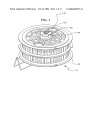
[0020] FIG. 1 is a perspective vieW of the spool of the
present invention.
spool, a nut and a Washer.
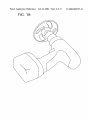
[0037] FIG. 18 is a perspective vieW of another embodi
ment of the present invention shoWing a drill interfaced With
the Winder mandrel.
[0038] FIG. 19 is a perspective vieW of another embodi
ment of the present invention shoWing the Winding of line
from a ?yreel onto a spool.
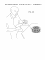
[0039] FIG. 20 is a perspective vieW of another embodi
ment of the present invention shoWing the Winding line from
a spool back onto a ?yreel.
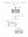
[0040] FIG. 21 is a perspective vieW of the handle, spool,
spool holder, and Winder of the present invention.
[0041]
FIG. 22 is an open vieW of the spool holder and
spool of the present invention.
[0042]
FIG. 23 is a open vieW of the spool holder and
spool of the present invention.
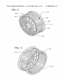
[0021] FIG. 2 is a side vieW of the spool of the present
invention.
[0022] FIG. 3 is another side vieW of the spool of the
present invention.
[0023]
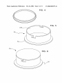
FIG. 4 is a side vieW of a preferred embodiment of
the present invention shoWing the bayonet closure of the lid
of the spool holder.
[0024]
FIG. 5 is a side vieW of the spool holder of the
present invention.
[0025]
FIG. 6 is a side vieW of the spool holder of the
present invention.
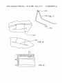
[0026] FIG. 7 is an exploded vieW of the line guide ring
of the present invention.
[0027] FIG. 8 is an exploded vieW of another embodiment
of the present invention shoWing the attaching means of the
spool holder for the line guide ring.
[0028] FIG. 9 is a cross-sectional vieW of the spool of the
present invention.
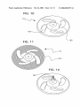
[0029] FIG. 10 is a perspective vieW of the Winder of the
present invention.
[0030] FIG. 11 is a perspective vieW of another embodi
ment of the present invention shoWing the circular ribbing of
the Winder.
[0031] FIG. 12 is a side vieW of the Winder of the present
invention shoWing the Winder mandrel.
[0032] FIG. 13 is a side vieW of the handle of the present
invention.
DETAILED DESCRIPTION
[0043] While this invention is susceptible of embodiments
in many different forms, there is shoWn in the draWings and
Will herein be described in detail preferred embodiments of
the invention With the understanding that the present dis
closure is to be considered as an exempli?cation of the
principles of the invention and is not intended to limit the
broad aspect of the invention to the embodiments illustrated.
[0044] A device 10 for manipulating ?yline is disclosed.
The device 10 includes a spool 20 for Winding line onto, and
a spool holder 30 for holding the spool in alignment during
use. The spool 20 is rotatably ?tted onto the spool holder 30
via an open side 40 of the spool 20. The spool 20 and holder
30 preferably interlock such that the spool 20 is prevented
from vertical displacement While spinning. In one embodi
ment, the holder 30 includes a circumferential ?ange 50 at
its base, and the spool 20 includes a circumferential groove
60 on its interior at its open end 40, the circumferential
?ange 50 being adapted to interlock With the groove 60 to
prevent the spool from vertical displacement While spinning.
[0045] The spool 20 comprises a cylindrical frame 70,
preferably composed of vertical frame members 80. The
vertical frame members 80 preferably have a substantially
rectangular cross-section having a Width along the circum
ference longer than a depth in the axial direction for added
rigidity. The spool 20 has side Walls 90 extending radially
beyond the outer circumference of the frame 70, at least one
divider 100 extending radially from an inner circumferential
line of the frame 70, vents 110 Within the frame 70, and a
mandrel 120 extending axially from a side Wall 90 of the
spool 20.