1
Feb. 26, 2004
US 2004/0035973 A1
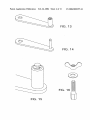
[0046] The mandrel 120 preferably has a threaded inter
face 130, and is adapted to receive a handle 140, such as via
being secured by a nut 150. Preferably, the mandrel 120 has
[0053] In a preferred embodiment, the Winder 170 is a
rubber disk, similar to a grinding disk, equipped With a
stainless steel mandrel 190, secured With a stainless steel
a threaded hole at the distal end for attachment via a screW
screW and Washers. The mandrel may be similar to the
160. The screW 160 preferably has a head With slanted sides
to form a substantially ?ush ?t With a base of the side of the
mandrel 120 on the spool 20. Four oblong slots are placed
opposite to each other at a 90° angle. Each pair of slots
preferably has a different diameter and spacing, in order to
accommodate a Wide variety of ?yreels, and may be curved
in order to lock into place With engaging components of a
spool 20, the spool side being adapted With slanted openings
to interface With the screW 160.
[0047]
The spool 20 ideally includes a means for attaching
a line, such as notches 210.
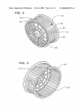
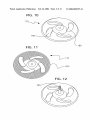
[0048] The system of the invention also includes a Winder
170 having openings 180 on at least one side for interfacing
With a ?yreel, and a Winder mandrel 190 extending axially
therefrom for use With a drill or handle 140. While a handle
Would not likely be used in this conteXt since the ?yreel
typically includes a handle, the handle 140 could be used if
the object being Wound has no handle. The Winder 170
preferably has four slots 180 comprising a ?rst pair and a
second pair on either side of the Winder mandrel 190, an aXis
of the ?rst pair running through the center of the Winder 170
and an aXis of the second pair being at a 90 degree angle
relative to the aXis of the ?rst pair.
[0049]
The Winder 170 is preferably composed of a rubber
disk, and the slots 180 are preferably curved so as to lock
engagement points on a ?yreel When turning and prevent it
from slipping out of center. In a preferred embodiment, the
Winder 170 includes circular ribbing 200 to prevent slipping
and to alloW for visual alignment.
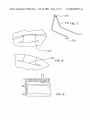
[0050] The spool holder 30 is preferably constructed of
plastic, and comprises a compartment having a cavity 220
for receiving a Weighted substance, such as sand or Water, to
hold the spool 20 in place in use. Ideally, attached to the
spool holder 30 is a line guiding means 230 Which can be
permanently or removably mounted to the spool holder 30.
The line guiding means 230 is preferably a rod or Wire
having a line guiding ring 240 through Which the line is
strung before usage. It can be attached via locking compo
nents 250.
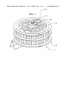
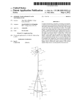
[0051] In another preferred embodiment, as shoWn in
FIG. 1, the spool 20 is made out of molded plastic, ?tted at
the closed face With a stainless steel mandrel 130, and held
in place With a stainless steel screW 160 and a Washer and nut
150. The spool 20 preferably has tWo Walls 90 on either side
to prevent line from slipping off the spool 20. The Walls 90
are preferably equipped With notches 210 to attach the
?yline. Preferably, the spool 20 also has a divider Wall 100
in four sections, to separate ?yline from backing. The spool
20 preferably has a very open construction so that the ?yline
can be cleaned thoroughly and afterWards can dry quickly.
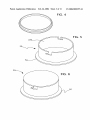
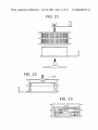
[0052] Also, in one preferred embodiment, the spool
holder 30 is a cylindrical boX With a lid, both made out of
molded plastic. The lid of the spool holder 30 is preferably
locked into place With a bayonet closure. Any other suitable
closure is also contemplated. The bottom of the spool holder
30 preferably has an anti-slip matting. The function of the
spool holder 30 is to serve as a guide for the spool to spin
around. The spool holder 30 can be Weighted, such as by
?lling it With sand or pebbles for eXtra stability. Also, the
spool holder 30 can preferably serve as a container for the
?yreel.
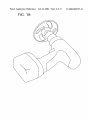
[0054] The spool 20 can be ?tted onto a drill, preferably
a cordless drill. Optionally, the mandrel 120 of the spool 20
is equipped With a threaded interface 130. The threaded
interface 130 alloWs for a handle 140 to be ?tted on the spool
20 for spooling line onto the spool manually. The drill
preferably has a progressive start and a reverse gear. By
activating the drill, the ?yline and/or backing is spooled onto
the spool 20.
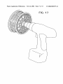
[0055] The Winder 170 preferably can also be ?tted onto
a drill. The Winder 170 is pressed onto the face of a ?yreel.
By activating the drill, the ?yline and/or backing is Wound
onto the ?yreel.
[0056] When spooling the ?yline and/or backing onto the
spool 20, the end of the ?yline is attached to the spool 20,
using one of the line attacher notches 210. By making the
drill turn, the ?yline and/or backing is stripped off the
?yreel. Once all the line is on the spool 20, it is untied from
the ?yreel. The spool 20 is removed from the drill and is
soaked in fresh Water for a period of time. Then it is left to
dry in the open air. When the line is dry, it can either be
Wound back onto the reel using the Winder 170 or the spool
20 can be stored With the line on it until the neXt use.
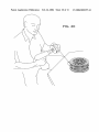
[0057] As shoWn in the ?gures, When Winding the ?yline
and/or backing onto the ?yreel, the spool 20 is slipped over
the spool holder 30 and the end of the ?yline and/or backing
is attached to the ?yreel. A groove 60 at an open end, on the
inside of the spool 20 ?ts over a circular ?ange 50 at the base
of the spool holder 30 to prevent the spool 20 from riding
upWards While spinning. There is also disposed on the spool
20 preferably a line guide ring constructed of stainless steel
or any other suitable material to give better control of the
line When spooling. The line guide ring 230, 240 is prefer
ably ?tted into slots at the bottom of the spool holder 30.
Alternatively, it is inserted in tWo holes in the base of the
spool holder 30. The line is slipped through the line guide
ring before spooling.
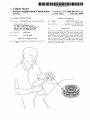
[0058] In one hand, the user presses the drill equipped
With the Winder 170 against the face of the ?yreel, Which is
held in the other hand, in such a manner that the slots in the
Winder 170 ?t around the handle and counter Weight found
on most ?yreels. The slots are curved in shaped to prevent
the ?yreel from slipping out of center While Winding line
back onto the reel. There is further a circular ribbing 200 at
the bottom of the Winder 170 to give the user visual guidance
to center the ?yreel on the Winder. The ribbing 200 also
prevents the ?yreel from slipping out of center While Wind
ing the line back onto the ?yreel. After making sure the
Winder is Well centered on the ?yreel, the drill is progres
sively started Which makes the ?yreel turn.
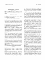
mandrels, screWs, Washers, and a user manual (see also FIG.
[0059]
23).
?yreel. The user makes sure the line is spread evenly on the
The ?yline and/or backing are thus Wound onto the