1
Contents
Section 01 Welcome to AMOS Professional
Chapter 01.01 Welcome
01.1.01 How to exploit this User Guide
01.1.02 A few words of welcome
01.1.05 A potted history of AMOS
Section 02 Installing
Chapter 02.01 Installing AMOS Professional
02.1.01 AMOS Professional Installation Procedure
02.1.03 Hard Disc Users
Section 03 Getting Started
Chapter 03.01 Getting Started
03.1.01 Absolute Beginners
03.1.02 The Edit Screen
03.1.03 Typing in the Edit Window
03.1.03 Your first programs
03.1.04 Direct Mode
03.1.05 Loading a program
Section 04 the Editor
Chapter 04.01 the Editor
04.1.01 The AMOS Professional Editor
04.1.02 The Edit Screen
04.1.02 The Edit Icons
04.1.04 The Editor Window
04.1.04 The Information Line
04.1.05 The Scroll Bar
04.1.05 Direct Mode
04.1.08 The File Selector
04.1.10 Saving and loading a program
04.1.11 Auto-save and Autoresume
The AMOS Professional editor menus
04.1.12 AMOS
04.1.13 Project
04.1.15 Editor
04.1.17 Macros
04.1.21 Block
04.1.22 Search
04.1.23 Config
04.1.27 User
04.1.28 Help
Chapter 04.02 Help
04.2.01 Calling for Help
04.2.01 The Help Window
04.2.02 Summoning help directly
Contents
04.2.03 Additional help
Section 05 the Basics of AMOS Professional
Chapter 5.01 the Bare Bones
05.1.01 Strings
05.1.01 variables
05.1.02 Naming variables
05.1.03 Types of variables
05.1 03 Storing variables
05.1.04 Arrays
05.1.05 Constants
05.1.05 Functions
05.1.06 Parameters
05.1.07 Procedures
05.1.07 Controlling a program skeleton
05.1.09 Separating commands in a line
05.1.10 Marking the bones of a program
Chapter 5.02 String functions
05.2.01 Reading characters in a string
05.2.02 Finding characters in a string
05.2.03 Converting strings
05.2.04 Manipulating strings
05.2.05 Getting infomation about strings
05.2.05 Array operations
Chapter 5.03 Maths
05.3.01 Arithmetical calculations
05.3.01 Calculation priorities
05.3.02 Fast calculations
05.3.03 Relative values
05.3.04 Values and signs
05.3.04 Floating point numbers
05.3.05 Single and double precision
05.3.06 Standard mathematical functions
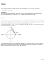
05.3.07 Trigonometry
05.3.10 Random numbers
Chapter 5.04 Control Structures
05.4.03 Decision making
05.4.04 Structured tests
05.4.06 Using loops
05.4.08 Conditional loops
05.4.09 Controlled loops
05.4.10 Forced jumps
05.4.12 Handling data
ii
Contents
Chapter 5.05 Procedures
05.5.01 Creating a procedure
05.5.01 Keeping track of procedures
05.5.02 Opening and closing procedures
05.5.03 Jumping in and out of a procedure
05.5.04 Local and global variables
05.5.07 Returning values from a procedure
05.5.08 Local data statements
Chapter 5.06 Text
05.6.01 Printing on the screen
05.6.02 Setting text options
05.6.03 Changing text options
05.6.03 Setting text styles
05.6.04 Changing the text mode
05.6.05 Positioning the text cursor
05.6.09 Tracking the text cursor
05.6.10 Changing the text cursor
05.6.11 Advanced text commands
05.6.12 Advanced printing
05.6.14 Sending text to a printer
Chapter 5.07 Windows
05.7.01 Creating windows
05.7.03 Manipulating windows
05.7.05 Creating slider bars
05.7.06 Displaying a text window
Chapter 5.08 The Joystick and Mouse
05.8.01 Joysticks
05.8.02 The mouse pointer
05.8.04 Reading the status of the mouse
05.8.06 Limiting the mouse pointer
05.8.06 Finding the mouse pointer
05.8.07 Displaying menus with the mouse pointer
Chapter 5.09 Memory banks
05.9.01 Memory bank numbers, names and types
05.9.02 Reserving a bank
05.9.03 Saving memory banks
05.9.04 Loading memory banks
05.9.05 Saving and loading memory blocks
05.9.06 Deleting memory banks
05.9.07 Swapping banks
05.9.08 Listing banks on the screen
05.9.08 Memory bank functions
05.9.09 Grabbing accessory program memory banks
iii
Contents
05.9.10 Automatic bank grabbing
05.9.11 Creating your own utilities
Section 06 Screen Control
Chapter 6.01 Setting up Screens
06.1.01 The AMOS Professional screens
06.1.01 Defining a screen
06.1.03 Controlling screens
06.1.04 Moving a screen
06.1.06 Manipulating screens
06.1.07 Clearing, hiding and showing screens
06.1.08 Screen priority
06.1.09 Defining screen colours
06.1.10 Screen functions
06.1.11 IFF screens
06.1.12 Extra Half Bright mode
06.1.12 Hold And Modify mode
06.1.13 Interlaced screens
Chapter 6.02 Using Screens
06.2.01 Copying screens
06.2.02 Scrolling the screen
06.2.03 Enlarging and reducing the screen
06.2.03 Physical and logical screens
06.2.04 Screen synchronisation
06.2.05 Screen compaction
Chapter 6.03 Screen Effects
06.3.02 Flashing colours
06.3.04 Rainbow effects
06.3.06 The copper list
Chapter 6.04 Graphics
06.4.01 Graphic coordinates
06.4.01 Setting the graphics cursor
06.4.02 Drawing lines
06.4.03 Drawing outline shapes
06.4.04 Selecting colours
06.4.06 Setting several colours
06.4.07 Filled shapes
06.4.08 Alternative fill style
06.4.10 Overwrite styles
06.4.11 Advanced techniques
Chapter 6.05 Menus
06.5.01 Using AMOS Professional menus
06.5.02 Reading a simple menu
iv
Contents
06.5.03 Creating advanced menus
06.5.05 The Menu control commands
06.5.07 Alternative menu styles
06.5.09 Moving menu displays
06.5.11 Moving a menu within a program
06.5.11 Keyboard shortcuts
06.5.13 Embedded menu commands
06.5.17 Automatic re-drawing of menus
Section 07 Object Control
Chapter 7.01 Hardware sprites
07.1.01 Normal hardware Sprites
07.1.01 AMOS Professional computed Sprites
07.1.03 Hardware Sprites versus computed Sprites
07.1.04 The Sprite command
07.1.06 The Sprite Palette
07.1.08 Sprite Commands
07.1.09 Conversion Functions
07.1.10 The Hot Spot
07.1.11 The Sprite Doctor
Chapter 7.02 Blitter Objects
07.2.01 Displaying a Bob
07.2.03 General Bob Commands
07.2.04 Unmasking Bobs
07.2.05 Bob Priority
07.2.06 Bobs and screens
07.2.09 Bob Bank Commands
07.2.10 Flipping Bob Images
07.2.12 The Bob Doctor
Chapter 7.03 Updating Objects
07.3.01 Moving multiple objects
07.3.02 Displaying objects over a changing background
07.3.02 The update process
07.3.03 The updating commands
07.3.06 The Autoback command
07.3.07 Bob drawing modes
Chapter 7.04 Detecting Collisions
07.4.01 Collision detection options
07.4.01 Types of collisions
07.4.02 Masks
07.4.03 The collision functions
07.4.06 Collisions with rectangular blocks
v
Contents
Chapter 7.05 IFF Animation
07.5.01 Optimising IFF animation
07.5.02 An overview of IFF animation
07.5.02 Creating an IFF animation
07.5.03 Playing an IFF animation
07.5.03 Direct IFF animation
07.5.07 IFF Masking
07.5.07 Freezing the display
Chapter 7.06 AMAL
07.6.01 The AMOS Animation Language (AMAL)
07.6.01 How AMAL is used
07.6.02 The AMAL guided tour
07.6.02 Moving an Object
07.6.03 Animating an Object
07.6.03 Moving within AMAL programs
07.6.04 AMAL registers
07.6.05 Logical decisions
07.6.07 Generating movement patterns
07.6.07 Playing a complex movement path
07.6.08 AMAL function list
07.6.11 Calling an AMAL program from AMOS Professional
07.6.12 Controlling update timings
07.6.12 Assigning Objects to Channels
07.6.13 Animating more than 16 Objects
07.6.13 Manipulating screens
07.6.15 The Autotest system
07.6.17 AMAL program control from AMOS Professional
07.6.20 AMAL errors
07.6.20 AMAL error messages
07.6.21 Compatibility with STOS animation commands
07.6.25 the AMAL editor
Chapter 7.07 Icons and blocks
07.7.01 Background screen graphics
07.7.03 Screen blocks
07.7.04 Compacted blocks
Section 08 Audio
Chapter 8.01 Music
08.1.01 Ready-made sound effects
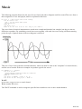
08.1.02 Musical pitch
08.1.02 Channels and voices
08.1.04 Playing notes
08.1.04 Making waves
08.1.08 Making audio envelopes
08.1.09 Playing music
vi
Contents
Chapter 8.02 Samples
08.2.01 Playing a sound sample
08.2.03 Changing a sample bank
08.2.03 Playing a sample from memory
08.2.04 Double buffered sampling
Chapter 8.03 Playing Music Modules
08.3.01 Playing AMOS Professional music
08.3.02 Playing Tracker modules
08.3.03 Playing Med modules
Section 09 AMOS Interface
Chapter 9.01 AMOS Interface
09.1.01 Introducing the Interface
09.1.01 The need for the AMOS Professional Interface
09.1.02 Introducing the AMOS Professional Interface
09.1.03 Variables and numbers
09.1.03 Setting a variable
09.1.04 Expressions
09.1.06 Resources
09.1.06 Calling an AMOS Professional Interface program
09.1.07 Creating a simple requester
09.1.07 Saving the background graphics
09.1.08 Waiting for an event
09.1.09 Interface buttons
09.1.11 Drawing a button
09.1.12 Changing a button
09.1.14 Keyboard short-cuts
Chapter 9.02 Interface language
09.2.01 The graphics functions
09.2.02 The graphics commands
09.2.02 Boxes and bars
09.2.04 Lines and Outlines
09.2.04 Displaying text
09.2.06 Labels and Tests
09.2.07 Interface conditional tests
09.2.08 User-defined functions
09.2.10 Machine code extensions
Chapter 9.03 Advanced Control Panels
09.3.01 Dialogue channels
09.3.03 Testing an active zone
09.3.04 Accessing a variable array
09.3.05 Advanced Control Panels
09.3.05 Editing zones
09.3.07 Sliders and Selectors
vii
Contents
09.3.09 Reading arrays
09.3.10 Displaying items on the screen
09.3.12 Creating a selector
09.3.14 Controlling a selector from the main program
09.3.15 HyperText
09.3.16 Creating some HyperText
Chapter 9.04 Interface Resources
09.4.03 The Resource commands
Section 10 Input/Output
Chapter 10.01 Using the Keyboard
10.1.01 Checking for a key-press
10.1.04 Keyboard inputs
10.1.05 Keyboard Macros
10.1.06 Improving your typing skills
Chapter 10.02 Disc Access
10.2.01 Disc drive names
10.2.01 Volume names
10.2.01 Files and directories
10.2.06 Checking for the existence of a file
10.2.07 Selecting a file
10.2.08 Naming files
10.2.08 Running programs from a disc
10.2.10 Disc space
10.2.10 Disc files
10.2.11 Sequential files
10.2.14 Random access files
10.2.16 Included files
10.2.17 IBM and ST users
Chapter 10.03 Accessing a Printer
10.3.01 The printer device
10.3.02 Embedded commands
10.3.03 Screen dumps
10.3.05 Other printer commands
10.3.06 Other ports and devices
Chapter 10.04 Accessing a Serial Port
10.4.01 Opening the serial port
10.4.02 Setting the serial parameters
10.4.03 Sending and receiving Serial information
10.4.04 Other serial commands
Chapter 10.05 The Parallel Port
viii
Contents
Chapter 10.06 AREXX
10.6.01 Using AREXX
10.6.02 AREXX-Compatible instructions
Section 11 Amiga Dos
Chapter 11.01 Fonts
11.1.01 Text Fonts
11.1.01 Graphic Text Fonts
11.1.01 ROM Fonts
11.1.03 Wiping fonts from memory
11.1.04 Assigning fonts
11.1.04 Converting font coordinates
11.1.05 The AMOS Professional Text Font Editor
Chapter 11.02 Speech
11.2.01 Synthetic Speech
11.2.03 The narrator Mouth
Chapter 11.03 Floating Point Numbers
11.3.01 Floating point libraries
Chapter 11.04 Multi-tasking
11.4.02 Communication between programs
Chapter 11.05 Libraries and Devices
11.5.01 Accessing the system libraries
11.5.03 Equates and Offsets
11.5.05 Adding equates to the equates file
11.5.06 The Requester extension
11.5.06 Control of devices
Section 12 Debugging
Chapter 12.01 the Monitor
12.1.01 Calling the Monitor
12.1.01 Using the monitor
12.1.03 The graphic output window
12.1.03 The Program Listing Window
12.1.03 The Information Window
12.1.03 Changing the window displays
12.1.04 The control keypad
12.1.05 Evaluating expressions
Chapter 12.02 Error handling
12.2.01 Trapping errors
Chapter 12.03 AMOS Errors
12.3.01 Editing error messages
ix
Contents
12.3.06 Program errors
12.3.09 Run-time errors
Section 13 Accessories
Chapter 13.01 Configuration
13.1.01 Defining a new accessory
13.1.02 AMOS Professional Configuration Files
13.1.02 Setting the Editor configuration
13.1.04 Setting the Interpreter Configuration
13.1.06 Saving memory
Chapter 13.02 Object editor
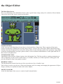
13.2.01 Loading the Object Editor
13.2.02 The Main Menu Screen
13.2.04 Disc Operations
13.2.06 Bank Operations
13.2.07 The Grabber
13.2.08 The Hot Spot
13.2.09 Palette Colours
13.2.10 Screen Resolution
13.2.11 Animation
13.2.12 The Object Editor Drawing Tools
13.2.15 Memory alerts
Chapter 13.03 the Menu Editor
13.3.01 Loading the Menu Editor accessory
13.3.01 The Main Menu
13.3.02 The Main Edit Screen
13.3.03 The Editor Menu
13.3.03 Item Status
13.3.03 Tree Editor
13.3.04 Draw menu
13.3.05 Item Drawing Screen
13.3.05 Draw functions
13.3.06 Settings
13.3.07 Object
13.3.07 Misc
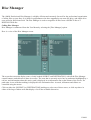
Chapter 13.04 Disc Manager
13.4.01 Calling Disc Manager
13.4.02 Entering a path name
13.4.02 Selecting files
13.4.03 Copying files
13.4.04 Examining files
13.4.05 Formatting discs
13.4.05 Copying discs
x
Contents
Chapter 13.05 the AMAL Editor
13.5.01 The AMAL String Editor Screen
13.5.02 The AMAL Editor Menus
13.5.02 AMOS menu
13.5.02 Edit menu
13.5.04 Recording and playing movement patterns
13.5.04 The Disc Menu
13.5.05 The Option Menu
13.5.05 The Block Menu
13.5.05 The Environment Generator
Chapter 13.06 the Sample Bank Maker
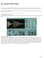
13.6.01 The Sample Bank Maker screen
13.6.01 The Current Sample window
13.6.02 The Sample Bank Window
13.6.02 Transfer buttons
13.6.02 The Information Line
13.6.02 The Control Panel
Chapter 13.07 the Resource Creator
13.7.01 The Resource Creator Main Menu
13.7.02 Editing Graphic Elements
13.7.03 Creating an Object
13.7.05 Editing text strings
13.7.06 Automatic Bank grabbing
Section 14 Appendix
Appendix 14.A: Machine Code
14.A.01 Converting numbers
14.A.03 Manipulating memory
14.A.06 Direct access to variables
14.A.09 Manipulating bits
14.A.11 Using assembly language
14.A.11 Machine code procedures
14.A.12 Creating a machine code language procedure
14.A.12 Communicating with a machine code procedure
14.A.13 Calling machine code from an address or bank
Appendix 14.B: AMOS Professional Run Time
14.B.01 Run-only discs
Appendix 14.C: NTSC vs PAL
14.C.01 International television standard systems
14.C.01 PAL versus NTSC
14.C.01 The display size
14.C.02 Screen updating and running speeds
14.C.03 Restricting programs to a single mode
xi
Contents
14.C.03 Dual mode programs
14.C.04 International television standard systems
Appendix 14.D: Extensions
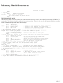
Appendix 14.E: Memory bank structures
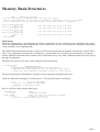
14.E.01 General Information
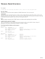
14.E.02 Memory bank headers
14.E.04 WORK BANKS and DATA BANKS
14.E.04 Work Banks and Data Banks stored in memory
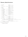
14.E.05 Work Banks and Data Banks stored on disc
14.E.05 Saving Several Banks at once
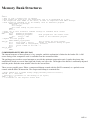
14.E.05 Format of Object Banks and Icon Banks
14.E.05 Object Banks and Icon Banks stored in memory
14.E.07 Object Banks and Icon Banks stored on disc
14.E.08 MUSIC BANKS
14.E.08 Music Banks stored in memory
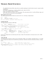
14.E.11 The Patterns
14.E.13 Music Banks stored on disc
14.E.13 SAMPLE BANKS
14.E.13 AMAL BANKS
14.E.14 The AMAL programs
14.E.15 THE RESOURCE BANK
14.E.16 COMPRESSED PICTURES (PIC.PAC )
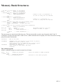
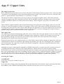
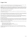
Appendix 14.F: Copper lists
14.F.01 The Amiga co-processor
14.F.01 The Copper List
14.F.01 Accessing the Copper
14.F.02 Recommended Procedures
Appendix 14.G: Command Index
xii
Welcome
AMOS Professional
Welcome to AMOS Professional, the dedicated creation system for producing professional Amiga programs. With
this system at your fingertips, you can exploit the full potential of your computer, and release the full creativity of
your own imagination. There is not a single style of best-selling computer game that cannot be produced with
AMOS Professional, and by reading through this User Guide and examining the hundreds of ready-made examples
on disc, you will soon discover that all of the hard work has been done for you.
AMOS Professional has evolved over several years until it can now provide beginners and experts alike with full
control over superb graphics, animation, audio sampling, synthetic speech, menus, interactive control panels, and
above all, ideas! Most importantly, you can customise AMOS Professional to suit all your own needs, quickly,
simply and precisely.
If you get into any sort of trouble, AMOS Professional offers instant on-screen Help with every command and
aspect of your programming, and there is even a built-in Program Monitor to examine what is happening within
your routines.
Experienced AMOS users will be amazed how many new features and improvements have been added to the
original system. Beginners will probably take it all for granted!
How to exploit this User Guide
A system that has been designed to satisfy all Amiga programming needs must offer its facilities clearly and simply,
otherwise the sheer scale of the package can seem overwhelming, and some of the system's wonders may be
completely overlooked by the user. To make this User Guide as helpful as possible, it has been divided into a series
of self-contained Sections, and each Section deals with a specific aspect of the AMOS Professional system. Where
these Sections cover several related subjects, each subject is examined in its own Chapter.
The number of the current Section and Chapter appears at the top corner of each page, with the page number printed
at the bottom corner. For example, this is page one of Section 1, Chapter 1, so if it appeared in the Index, it would
be referred to as 1.1.01, whereas the first page of Chapter 8 in Section 5 would be referred to as 5.8.01.
However, the printed word can never convey the look and feel of a programming technique, which is why
everything that you read in these pages can also be demonstrated and analysed on screen, at the touch of a button!
AMOS Professional comes complete with pre-programmed instant examples of everything from a single command
to complete arcade games, strategy simulations and practical utilities!
Normally, you will be able to call for ready-made demonstrations and Help directly, but where it is necessary to
load a particular demonstration program from a disc, a special pointer symbol is used in this User Guide. Similar
pointers also appear to make it clear which examples you can type in.
01.01.01
Welcome
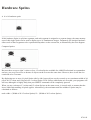
There are four different pointers that can appear at the left-hand side of the page, and they have the following
meanings:
DP> Disc Pointer. Please load this ready-made demonstration program from disc.
E > Edit Pointer. This printed example can be typed in exactly as it appears on the page, from the AMOS
Professional Edit Screen. It can then be Run, and is seen on screen.
D> Direct Mode Pointer. This printed example can be typed in exactly as it appears on
the page, from the AMOS Professional Direct Mode Window. It can then be demonstrated by pressing the [Return]
key.
X> This printed example demonstrates a particular programming technique or part of a routine. There is no need to
type it in, because it cannot be demonstrated in isolation on the screen.
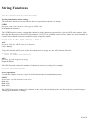
Printed examples of AMOS Professional programs appear in special type, and they are indented on the page like
this:
E>AMOS=1
Print AMOS
AMOS Professional provides over seven hundred command words ready to be exploited in your own programming
routines, and many of them are staggeringly powerful. Because these command words are so important, they are
printed in prominent type throughout this User Guide. When they appear in the main body of the text, they are
printed in capital letters. For example the simple command word for printing items appears as PRINT. Where a
command word is introduced for the first time in the User Guide, it is indented on the page and printed in large bold
type, along with a summary of its use. For example:
PRINT
instruction: print items on screen
Print items
Everything else is fully explained as it is introduced, or is completely self-explanatory. Now that AMOS
Professional has been introduced to you, and before introducing AMOS Professional to your Amiga, here are a few
words of welcome from some of the key players in the team.
A few words of welcome
Welcome to AMOS Professional! Many thanks for buying it and many more thanks for helping us create it. Since
your feedback from the very first versions of AMOS, we have had one constant policy of listening to you, the user.
We have read every letter, and recorded all your comments, suggestions, bouquets and custard pies! Everything has
been evaluated and taken into account, and the result is in your hands right now.
01.01.02
Welcome
So much has been added to the original software, and special attention has been paid to the interface between our
software and your brain: the Editor.
I really want you to be comfortable within AMOS Professional, and I am happy to tell you that the Editor can be
reconfigured to exactly how you like it, and I mean exactly. You can even reprogram my menu options.
We'll keep on listening to your suggestions, so please fill in the Registration Card and when you have taken a little
time to discover the insides of AMOS Professional, tell us your impressions of the product. Old AMOS users, you
are in for a big shock! New users, I want you to be surprised, delighted and made passionate by my software!
FRANÇOIS LIONET
Is it really five years since two French guys visited our offices with STOS Basic in tow? It had sold a couple of
thousand units in France and all its support programs looked terrible! But there was something magical under the
hood: STOS had an amazingly fast sprite engine, a powerful music facility, and it was perfect for writing games.
We got incredibly excited, decided to publish STOS in the UK as The Games Creator, and got the author to write a
Low res sprite editor and a game, for which we supplied all the graphics. STOS was transformed! It was launched in
August 1988 and stormed straight to Number One in the Gallup Charts. It has since sold 40,000 copies through the
shops, and a further 90,000 when Atari bundled it with the ST for a year.
AMOS was started soon after the STOS launch. Until then, François had hardly seen an Amiga, and boy, did he
have problems coming to terms with its idiosyncrasies! Since then, AMOS has transformed the lives of hundreds of
thousands of Amiga programmers! Easy AMOS followed on, to meet the demands of first-time programmers.
François made so many improvements to the original environment that we had to give AMOS a complete overhaul,
and the result is AMOS Professional: what must be the most sophisticated development system for the Amiga yet. I
am sure that as you use AMOS Pro you will appreciate the sheer amount of hard work and love that François,
Richard, Mel, Stephen, Ronnie and the team have put into the package. They have worked long hours, seven days a
week to bring you their pride and joy, based on conversations and questionnaires from very many AMOS users. I
hope that this is exactly what you've been waiting for, and I wish you many happy hours using AMOS Pro to
transform your dreams into reality.
CHRIS PAYNE
I've been involved with AMOS from the very beginning. It's been a wonderful program to work with and I have
always been excited by each new version created by François. With AMOS Professional we have turned the tables
on you, the user. Instead of dictating what this new version was to be, we contacted over two hundred AMOS
enthusiasts to see what they wanted. From their replies we created a Wish List of major features. The ones that made
the most sense and offered the greatest benefits to the majority of users were grafted into the system. AMOS is a
very wholesome product, and it leaves no boulders unturned. Its creative powers allow you to produce endless types
of programs. Have strength in all your programming efforts, and if your human machine tries to defeat you and you
feel like giving up, rely on the strength of AMOS Professional. The satisfaction is well worth the effort. Go for it!
RICHARD VANNER
01.01.03
Welcome
I remember my first glimpse of AMOS Basic, three years ago. A package popped through my letter box containing a
three-and-a-half-inch disc bearing the label AMOS-1 written in biro. Ten minutes later I was completely hooked!
All through the next year, new versions arrived on my welcome mat, and I never quite knew what to expect. It was
like opening Christmas presents every week! There were many surprises along the way, including the AMAL
animation language, but the potential of the system was obvious from that first disc. As the project drew to a close, I
resolved to get down to some serious AMOS programming. Three years and several hundred programs later, I'm
still raring to go!
It looks like Christmas has arrived early this year, and I'm even more enthusiastic about AMOS Professional. It
heralds an exciting new chapter in the world of Amiga programming, and I'm delighted to be part of it. There are
dozens of great new features, and I have already programmed each and every one of them. AMOS has provided me
with years of enjoyment, and AMOS Professional promises more to come. So join me on an extended journey into
the fascinating world of AMOS Programming. you won't regret it!
STEPHEN HILL
When I first became interested in computers, they were an unknown quantity. Friends would ask me, "What can you
do with a computer?", and there I was for six hours a night with my ZX80, 1k RAM, no colour, no sound, no
graphics, writing 101 different programs that printed my name to the screen. At the time I didn't have an answer to
their questions. About twenty years have passed since I plugged in my first transformer, and home computers have
evolved into powerful and complex beasts. AMOS Professional is the tamer of my beast, and with a little effort on
your part, I'm sure it will become one of your best friends as well. Since using the AMOS system, I have the perfect
answer to the old question "What can you do with a computer?" I simply reply, "Anything I like!"
RONNIE SIMPSON
I was a computing crustacean: a creature with an interesting past and possibly extinct. I evolved from the digital
slime when computers were as big as a whale and as daft as plankton. Two years ago They said to me "This is an
Amiga, and this is Easy AMOS. If someone like you can understand how the two go together, then anyone can!" I
understood. I evolved. There were only three things wrong with Easy AMOS: it was sleeker, smarter and friendlier
than its big brother AMOS. So now They have come up with AMOS Professional. I can understand this too. I have
evolved some more.
Now I'm a computing dolphin: streamlined, intelligent, well-loved and a protected species. Thanks everyone.
MEL CROUCHER
01.01.04
Welcome
A potted history of AMOS
We end this Welcome, with a brief summary of the evolution of AMOS Professional.
Christmas 1986: the first lines of STOS are written for the Atari-ST.
November 1987: STOS is launched in France, with staggering sales of four dozen copies.
Spring 1988: Mandarin Software agree to publish STOS in England, provided that one or two improvements
are made.
Autumn 1988: STOS launch is greeted with acclaim, success and the recognition that an Amiga version may
be of some interest.
February 1989: launch of the STOS Compiler.
April 1989: AMOS programming commences, and comes to a temporary halt on 19th March 1990, when
François Lionet is conscripted into the French army. Programming is completed in uniform, in secret and
under stress.
June 12th 1990: launch of AMOS V1.1.
August 1990: manual and extras disc are added.
September 1990: after feedback from users, AMOS V1.21 is launched. Updates are put into the Public
Domain, making them free to the already loyal band of AMOS users. Programming begins on the AMOS
Compiler.
March 1991: Monsieur Lionet's military service comes to an end, and the French version of AMOS is
launched to celebrate this event.
June 1991: AMOS Compiler and AMOS V1.3 are both launched.
July 1991: AMOS-3D is released, and a streamlined beginner's AMOS is commenced. This is to be called
Easy AMOS, and published under Mandarin's new identity, Europress Software.
August 1991: Madame Lionet begins production of a dedicated junior programmer, due for launch in May
1992.
February 1992: Easy AMOS programming completed, AMOS Compiler updated and AMOS VI 34 finished
March 1992: AMOS Professional evolves from AMOS improvements, Easy AMOS features and feedback
from users.
April 23rd 1992: Easy AMOS launched.
May 1992: simultaneous launch of German AMOS and Baby Lionet.
Autumn 1992: the launch of AMOS Professional, with a warm welcome.
March 1993: Baby Lionet says his first word. "AMOS!"
01.01.05
Installing Amos Professional
The AMOS Professional package contains this User Guide, an accompanying Applications Supplement, your
Registration Card and the following floppy discs:
System disc (AMOSPro_System:)
The System Disc contains the bones, muscles, heart and soul of AMOS Professional! All of the system libraries are
held here, as well as items such as communications devices, fonts and the installation program.
Examples disc (AMOSPro_Examples:)
This disc is packed with hundreds of instant examples of AMOS Professional in action. These files can be
summoned up as you program, via the superb AMOS Professional Help system.
Tutorial disc (AMOSPro_Tutorial:)
For detailed step-by-step examples on specialised subjects, the Tutorial disc offers private tuition on a range of
topics, including animation, special effects, menus, Bobs and Sprites.
Accessories disc (AMOSPro_Accessories:)
This disc contains a full range of AMOS Professional Accessories.
Productivity discs 1 and 2 (AMOSPro_Productivity1:,AMOSPro_Productivity2:)
These discs feature complete AMOS Professional games and utilities. All programs are fully annotated and ready for
you to enjoy, explore and adapt. Full details of these ready-made AMOS Professional programs are contained in
your Applications Supplement booklet.
AMOS Professional Installation Procedure
To prepare AMOS Professional ready for your exploitation and enjoyment, the System Disc must be installed for all
users, and other features made accessible for hard disc users. This is very simple and all instructions are displayed on
screen, step by step. Here is an outline of the installation procedure from a floppy disc:
Step One
Take the disc labelled AMOSPro_System:, and make sure that it is write-enabled. In other words, ensure that the tab
at the top right-hand corner of the disc is in the closed position, so that it covers the small square hole. This will
allow you to personalise your copy of AMOS Professional, with your own name appearing on screen to greet you.
If your Amiga is switched on, make sure that the drive light is not illuminated, and take out any disc that may be in
the drive. Switch off your computer and wait about twenty seconds to let it clear its memory and forget any bad
habits that may be lurking there.
Place the write-enabled AMOS Professional System Disc into the internal floppy drive, and switch on.
Step Two
Sit back and enjoy the AMOS Professional animated musical introduction! After a short pause, this screen fades and
the next screen appears.
02.01.01
Installing Amos Professional
Step Three
This is the Registration Screen, asking you to type in your first name and last name, then click on the [OK] panel
with the mouse.
In this User Guide, whenever an option is referred to that appears on the screen, waiting to be selected, it is enclosed
in square brackets on the printed page.
If you make a mistake when typing, you may insert your first or last name again, and when both names are entered
correctly, trigger the [OK] button.
If for some reason this operation is unsuccessful, a screen will appear advising you what to do. Please make sure that
you are using your original AMOS Professional System Disc, and that it is write-enabled before proceeding. If all
else fails, and your disc drive is opera ling correctly, and if the disc in the drive is the original write-enabled System
disc, then there must be a fault on the disc. Please return it for a free re-duplication to:
AMOS Professional Customer Support
Europress Software Ltd.
Europa House
Adlington Park
Macclesfield
SK10 4NP
England
Telephone: 0625 859 333 (UK), or +(44) 625 859 333 (International) Fax: 0625 879 962 (UK), or +(44) 625 879 962
(international)
Fortunately, you are very unlikely to encounter a faulty disc, and there should be no problems in having your name
accepted before proceeding to the next step.
Step Four
The AMOS Professional registration screen appears, containing your unique Registration Number. Write down this
number now, and also copy your Registration Number onto the following items:
All of your original AMOS Professional disc labels.
The Registration Panel on the inside front cover of this User Guide.
Your AMOS Professional Registration Card. Please return this card to Europress Software (Freepost), and
take full benefit of the AMOS Professional Customer Support service, but make sure that you have used
AMOS Professional for at least two weeks before doing so.
Remember to quote your unique Registration Number when contacting Europress Software with any enquiries.
Click on the [OK] panel to reveal the next screen.
02.01.02
Installing Amos Professional
Step Five
This is the Installation Screen, and your System Disc will now boot directly into AMOS Professional. If you want to
boot from floppy disc, press [Ctrl]+[Left Amiga]+[Right Amiga] now. Hard disc users should continue as explained
below.
In this User Guide, whenever you are asked to press a particular key, the key is enclosed in square brackets on the
printed page. When two or more keys should be pressed at the same time, a plus sign is used to link the individual
keys together. So to boot AMOS Professional from floppy disc now, you are asked to press the control key at the
same time as both of the special Amiga keys that are either side of the space bar on your keyboard, or [Ctrl]+[Left
Amiga]+[Right Amiga].
Now is the time to fill in your Registration Numbers and back up your original AMOS Professional discs. Making
copies of discs is very simple, using the AMOS Professional Disc Manager utility, which is fully explained in
Chapter 13.4.
Hard Disc Users
With the Installation Screen still displayed, hard disc users should click on the [OK] panel. The start-up sequence is
changed from running the Installer to running AMOS Professional, but the Installer can be recalled by doubleclicking on its Workbench icon.
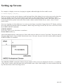
Step Six
Hard Disc Users are taken to the AMOS Professional Hard Disc Installation Screen. When this appears, simply
indicate which items you would like installed onto your hard disc, and as each item is selected, the appropriate
number of kilobytes required will be shown. You have the option to [Quit] at this stage, in which case you will be
returned to the Workbench or CLI, depending on how the Installer was booted. Otherwise, when the required items
have been selected, click on [Install].
Step Seven
If [Install] is chosen, a file selector appears, and you are requested to select the device and current path for the
installation of AMOS Professional. After making your selection, click on [OK] to proceed to Step Eight of the
Installation procedure. Alternatively, the [Cancel] option will return you to Step Six again.
Step Eight
Everything is now automatic. If there is not enough memory available on the selected device, this fact will be
reported. You will be returned to Step Six to make a more modest selection. Otherwise, a loading and saving
sequence is displayed, consisting of an Installation report for each named file, in the form of a percentage figure and
an animated bar.
Step Nine
Once all files have been successfully installed on hard disc, a final report is displayed, along with an option to
[Quit].
The installation procedure will analyse what type of system it is being installed onto and will configure your AMOS
Professional software appropriately.
See Chapter 13.1 regarding these settings.
02.01.03
Getting Started
AMOS Professional is a truly comprehensive programming package, allowing experts to release their full potential.
It has also been designed to provide beginners with rapid access to expert techniques. However, this section is for
absolute beginners only!
If you have upgraded from Easy AMOS or its big brother AMOS, don't be too proud to skip through this Chapter
before moving on to Chapter 4.1, where the AMOS Professional Editor is explained.
Warning: if you have not yet installed your AMOS Professional System disc, please do so now by referring to
Chapter 2.1.
Absolute Beginners
A computer program is simply a collection of instructions telling a computer to perform a list of tasks. Amiga
programs are stored on magnetic discs, and because disc programs are stored magnetically, you must keep them
clear of all magnetic objects. Placing a telephone on top of a hard disc drive can be a risk, and leaving floppy discs
on top of your television set or loudspeaker system is asking for trouble. Always make back-up discs of your
programs, and store them in a safe place out of direct sunlight.
Computer programs that are stored on magnetic discs have to be "loaded" into your computer's memory. If you are
using floppy discs, here is the procedure for loading AMOS Professional:
To explore all of the system's features, a colour television or monitor should be connected to your Amiga via
the appropriate cable. Additionally, a stereo audio system should be connected to the computer's left and right
audio sockets. Make sure that your mouse is also connected to the appropriate socket.
Remove any disc that may be in your Amiga's internal floppy disc drive, switch off the machine, and wait at
least ten seconds.
Place your AMOSPro_System disc in the Amiga's internal floppy disc drive and switch on the computer.
AMOS Professional will load into the machine's memory automatically.
Remember to make back-up copies of your original AMOS Professional discs, and keep the originals in a safe
place.
Hard disc users who want to load AMOS Professional from the Workbench once it has been installed should
double-click on the AMOS Professional System disc icon, and then click on the relevant icon to run the program. If
you are running the system from CLI, simply type in:
AMOSPro
03.01.01
Getting Started
AMOS Professional has been designed to be the friendliest system available to the Amiga programmer. As soon as
it has loaded into your computer, you will be greeted by name before getting down to business! This welcome panel
will disappear automatically after a few seconds, or it can be cleared by pressing any key on your keyboard, or by
clicking a mouse button.
The Edit Screen
To create and edit computer programs with AMOS Professional, you are given a working area called the Edit
Screen. If AMOS Professional has been loaded successfully, the Edit Screen will be displayed now.
There is a complete guided tour of the AMOS Professional Editor in the next Chapter, but you will want to see some
immediate action. So instead of explaining what everything does, here is a rapid introduction to getting started.
Move the mouse around now, and observe how the mouse pointer follows your movements around the Edit Screen.
At the top of the Edit Screen there is a row of control "buttons" that are used to call up various features of the
AMOS Professional system. These little panels are triggered by dragging the mouse pointer over one of them, and
clicking with the left mouse button. You can do no harm by experimenting with any of the Edit Screen features, but
please resist the temptation to do this, and follow this brief introduction.
Identify the control button at the top-centre of the screen, displaying the letter [H]. Move the mouse pointer over it
and click the left mouse button. This is the [Help] icon, and it calls up the AMOS Professional instant Help service.
Now look at the new display on the screen, and identify the small button to the immediate left of the title "AMOS
Professional Help Window", and click on it to return to the original Edit Screen display.
Now press the right mouse button and keep it held down.
When editing, the right mouse button calls up a line of "menu" titles at the top of the Edit Screen. Run the mouse
pointer along this line of titles now, and notice how as soon as the pointer touches one of them, a selection of
further titles is revealed. Each of these items refers to a different feature of the AMOS Professional system.
With the right mouse button still held down, move the mouse pointer to the right-hand side of the line of main menu
headings, and touch the [Help] title. Keeping the right mouse button held down, move the mouse pointer to the
[Help Menu] option, so that it is highlighted in reverse video. As soon as you release the right mouse button, this
feature is called up on screen.
Please clear the Help Main Menu from the screen by pressing the small button as before.
Now look at your keyboard, and identify the large [Help] key. Press this key now, and the AMOS Professional Help
Main Menu is called up once more. Before proceeding, please clear it away again, as described above.
03.01.02
Getting Started
You are already using AMOS Professional like an expert, and have just used the three alternative methods of calling
up one of the most useful AMOS Professional features, as follows:
Clicking on a control button, or "dialogue" box, or "icon", using the mouse. You will soon learn how to design
your own control buttons and dialogue boxes.
Calling up a Menu and selecting one of the items on offer, using the mouse. You will also learn how to exploit
your own menu designs.
Pressing one or more keys on the keyboard directly.
Typing in the Edit Window
If you have been experimenting, and cannot clear the Edit Screen to its original empty state, leave your machine
switched on, with the AMOSPro_System disc in the internal floppy disc drive, and press the
[Ctrl]+[Amiga]+[Amiga] keys together. This will re-boot AMOS Professional, allowing you to clear your electronic
slate.
Look at the empty Edit Screen, and identify the small flashing block in the top left-hand corner of the large area
below the row of control buttons. This is the "program cursor" and it marks the current position where anything you
type in will appear on screen. This top left-hand position marks the "home" starting point of the Edit Window,
which is where the list of instructions that make up your computer programs begin to appear.
Press the [A] key on your keyboard, and a lower-case "a" will appear in the Edit Window, shunting the program
cursor one character to the right. Now hold down one of the [Shift] keys and press [A] again. There should now be a
capital "A" next to the little "a" on screen. The [Shift] key is used to type in upper-case letters as well as any of the
symbols that are marked above the numbers and punctuation marks on your keyboard keys. So to type in a "$"
symbol, you would press [Shift]+[4] together. Type in a "$" now.
Now locate the extra-large key with a turn-left arrow on it, to the right-hand side of the main block of keys. This is
the [Return] key, and it is used to start a new line when writing programs. Please press this key once, so that the
program cursor is waiting at the beginning of a new line.
Just above the large [Return] key, there is a small key marked by a left-arrow. This is the [Delete] key, and it is used
to rub out characters already typed in the Edit Window. Please press it as many times as necessary to get rid of any
characters that you have typed, until the cursor is back "home" in the top-left corner of the Edit Window.
The mouse pointer can also be used to position the program cursor in program lists, as well as to mark out special
blocks of the program, and this will become obvious in the next Chapter.
Your first programs
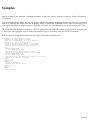
Type in the following program so that it appears in the Edit Window, and then press the [Return] key:
E>Print 2+2
03.01.03
Getting Started
That juvenile program will wait in the Edit Window, until you tell AMOS Professional to "run" it. To run a
program, call up the list of Menu headings by holding down the right mouse button, move the mouse pointer to the
[Project] title, highlight the [Run] option and release the right mouse button.
Alternatively, use a simple keyboard short-cut for running a program, which is to press the [Fl] key. Either way, the
Edit Screen will be flicked out of view, and the result of the program will be displayed on screen. In this case, the
result of two plus two will be printed on screen as "4".
There are several ways to return to the Edit Screen when a program is running. There are special commands that can
be included in the program for an automatic return, which will be explained in future Chapters, or you can break
into a program by pressing the [Ctrl]+[C] keys together, and then press the [Return] key.
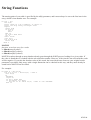
If an audio system is connected to your Amiga, add the following lines to your program, so that it now looks like
this:
E>Print 2+2
Wait 100
Boom
Wait 200
Print "Good-bye"
Wait 50
Edit
Now press [Fl] to run that program. You should already be aware that using AMOS Professional is a very friendly
method of communicating with your Amiga.
Direct Mode
So far, you have been programming your Amiga in the AMOS Professional Edit Mode, but when you are working
on a program professionally you will often want to conduct an instant experiment, or call up an AMOS Professional
feature without interfering with your current task. There is a very powerful Direct Mode provided for this purpose,
which works completely independently from the Edit Mode. To jump to Direct Mode now, use the mouse to click
on the [Arrow] button in the top left-hand corner of the Edit Screen, or alternatively press the [Esc] key at the top
left-hand corner of your keyboard.
The Direct Mode screen is flicked into view over the Default Screen, and it can be repositioned to reveal the
contents of the Default Screen behind it, by clicking on the [DIRECT] panel in the line of control buttons with the
left mouse button, and dragging the Direct Mode screen up and down. To get back to the Edit Screen, press the [Esc]
key again, or click on the [Arrow] button at the top left of the Direct mode "window".
There is a highlighted prompt in the Direct Mode window, waiting for your instructions to be typed in and displayed
next to it. After they have been typed in, these instructions will be obeyed as soon as the [Return] key is pressed,
without interfering with the program that is
03.01.04
Getting Started
currently being worked on in the Editor. Type the following line in Direct Mode now, and then press the [Return]
key.
D>Print "This is Direct Mode"
Direct Mode offers a simple way of gaining access to a disc, to examine its contents, or load some images. It also
allows you to check the results of instant tests of text, graphics and sound commands, before including them in your
programs. Try out the following lines from Direct Mode now, and remember to press [Return] after typing in each
line. The first line instructs AMOS Professional to report how many little dots known as "pixels" make up the height
of the current screen. The middle line calls for a report of how much free chip memory is available. The third line
triggers a print-out of the contents of the current disc, known as a "directory".
D>Print Screen Height
D>Print Chip Free
D>Dir
There is a full guided tour around all of the Direct Mode operations in the next Chapter.
To end this beginner's introduction, take a look at some ready-made programs that have been created by other
programmers using AMOS Professional. If you have been experimenting, and are not quite sure of everything that is
displayed on screen at the moment, leave your AMOSPro_System disc in place, and press [Ctrl] + [Amiga] +
[Amiga] to make sure that you start from scratch again.
After being greeted by your name, and revealing the Edit Screen, remove your AMOSPro_System disc and insert the
disc labelled AMOSPro_Productivityl.
Loading a program
As usual with AMOS Professional, you have a choice of how to select the loading operation. You can call up the
Main Menu titles with the right mouse button, and select the [Load] option from the [Project] menu in the usual
way. Alternatively, there is a keyboard short-cut by pressing [Amiga] + [L]. Either operation will call up a special
interactive panel called a "File Selector". A file is simply a self-contained chunk of computer data, with its own
name, held on a magnetic disc.
With the File Selector in the middle of your screen, use the mouse pointer to highlight one of the programs on offer,
and click on the [Return] icon. If you are interested in an arcade game, you can select and highlight the line that
reads Zybex/Zybex.AMOS, or if you prefer a practical program then Fileo'fax.AMOS is worth examining.
Certain programs need more memory than others, and if there is not enough memory available when you want to
load a particular program, you will be presented with a "dialogue box" on the screen, asking if you want to expand
the size of the relevant memory. When dialogue boxes are presented by AMOS Professional, you normally select
your response using the mouse pointer and clicking on the left mouse button.
03.01.05
the Editor
Welcome to the AMOS Professional Editor! It is assumed that you have either read the last Chapter, or are already
familiar with AMOS or Easy AMOS.
AMOS Professional provides one of the most effective and powerful creative environments for the Amiga
programmer. It is also incredibly simple to use. Here is a synopsis of the AMOS Professional enhancements and
improvements over the previous incarnations of the Editor.
The size of the Editor working area has been dramatically increased.
The increased working area is made possible by the provision of a comprehensive system of pull-down menus.
The main menu headings are invisible until they are revealed by pressing the right mouse button. The second
part of this Chapter provides a detailed guided tour of the vast selection of menu options.
The on-line Help system that was offered by Easy AMOS has been enhanced beyond recognition! Instant
Help is available for any command, offering definitions, correct syntax and working examples. This allows
instant insights into the hundreds of new commands provided by AMOS Professional for existing AMOS and
Easy AMOS users. Chapter 4.2 contains a full analysis of the Help system.
A Monitor accessory can be called for analysis and reports of actual program listings, and this is explained in
Chapter 12.1.
AMOS Professional features a split-screen Editor, allowing you to flick from program to program with a
single mouse click.
There is immediate access to printer support, and listings can be printed by selecting a single menu option.
The block system has been dramatically improved, and given its own mode. Block Mode can be entered by
double clicking on the left mouse button, or by summoning the [Block] menu.
The SET BUFFER command is now intelligent, allowing you to increase the memory area at any time,
without the necessity to save programs first.
Finally, the File Selector is new, improved and extremely friendly!
The AMOS Professional Editor is very easy to use, and it may be tempting to pick up the system as you go along,
particularly if you have experience of AMOS or Easy AMOS. After a few weeks of use, the exploitation of the
Editor features will become almost instinctive.
However, if you plunge into the system without a little guidance, you may well end up using only a fraction of the
Editor's potential capability. The sheer power of the system is vast, and it would be a pity to overlook some of its
exciting features. It is possible that you may only need to refer to this Chapter once, but please make sure that you
are aware of everything that the AMOS Professional Editor has to offer.
The AMOS Professional Editor
The purpose of the Editor is to make it as easy as possible to create, adapt and modify AMOS Professional programs
via your screen. To achieve this, the Editor provides a range of tools that have been designed with the sole purpose
of saving Amiga programmers time, trouble, frustration and confusion. It also short-circuits the need for ugly,
complex program listings!
The Editor is intelligent, and will recognise AMOS Professional instructions as they are typed in, allowing mistakes
to be corrected immediately.
04.01.01
the Editor
You can even tidy up your program listings with an automatic indenting option, and make them pleasing to the eye
and more accessible to the brain.
You are able to move through your streamlined listings at high speed, jumping from one label or procedure to the
next. The procedures themselves are complete program modules that can be compacted into a single line of your
listing by "closing" them.
Wherever possible, the AMOS Professional Editor will call up Help at the touch of a button, whenever you need it.
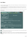
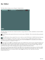
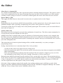
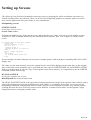
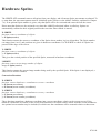
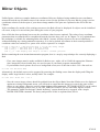
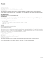
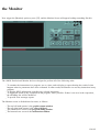
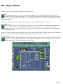
The Edit Screen
Here is a diagram of the AMOS Professional Edit Screen. There follows a short guided tour of its features.
The Edit Icons
The [<D] button at the top-left of the screen is used to go into Direct Mode. This is also achieved by pressing
the [Esc] key. Direct Mode is fully explored later.
The [WB] button at the top-right of the screen is used to go to the Workbench. If AMOS Professional has been
loaded from the Workbench, it will remain in memory, and you can return to AMOS Professional by pressing [Left
Amiga]+[A].
04.01.02
the Editor
The [WB] button will have no effect if the CLOSE WORKBENCH command has been called from one of your
programs, as explained in Chapter 13.1.
Between the [DIR] and [WB] buttons, there is a line of icons that provide rapid access to various features, directly
from the screen. From left to right, they have the following uses:
As usual, all of these icons are activated by the left mouse button. This is the [RUN] button, and it is used to
run the current program listing. If any errors are encountered in the program, a message will be displayed in the
Information Line.
The [TEST] button instructs AMOS Professional to test the current program for errors, without running the
program. A full list of error messages is listed in Chapter 12.3, and the Help facility is available to explain the
correct use and syntax of instructions.
[INDENT]. Use this button to automatically indent your program listings. Where example programs are printed
in this User Guide, they are displayed in indented format.
This icon is used to summon up the AMOS Professional [MONITOR], which provides detailed help and
analysis of your programs. A full explanation of the Monitor can be found in Chapter 12.1.
[HELP]. The next Chapter provides a detailed examination of the AMOS Professional help facilities. Use this
button to call up the Help main menu.
[UNDER] and [ABOVE]. This pair of buttons is used to display the window which is under or above the
current window, in other words it moves to the previous or next window.
The [INSERT/OVERWRITE] button toggles between the two modes of editing, which are explained in the
paragraphs concerning the Information Line, below.
The [PROCEDURES] icon is used to open or close a procedure. Unlike the image of the last button, which is a
toggle, this icon is an animation, and after being activated it returns to its original state.
This icon represents [INSERT A RETURN], and its use is dealt with in the explanations of the menu options.
The two indicator bars to the right of the above icon buttons display the amount of Chip and Fast
memory that is currently being used.
04.01.03
the Editor
The Editor Window
The windows that hold program listings appear immediately below the row of Edit icons.
At the top of each window is an Information Line, that displays the title of the current "project" and provides a
status report. It also displays three Edit Window Icons, as follows:
At the left-hand side of the Information Line, there is a small [CLOSE] icon. This closes the current window
and erases its contents.
Since this is a drastic action, you will be asked to confirm your intentions before the window is closed. Select
[Cancel] to abort the closing operation, and leave the current program intact. Please note that when the last window
is closed in this way, the program will be erased and the window will be left clean, ready for your next editing
action.
You may wish to open a new window now, before experimenting any further. Please hold down the right mouse
button and with the button held down, drag the mouse pointer to the [Project] menu heading and highlight the [Open
New] option. Now release the right mouse button, and a new window will be opened at once. You can open more
windows if you wish, to prove how simple this is, and then close them again with the [CLOSE] button.
You are allowed as many active windows as you wish, providing that there is enough screen space. Once a window
has been opened, it may be re-positioned by dragging its Information Line using the left mouse button, and its size
can be changed by dragging its lower border in the same way.
Only one window can be active at a time, and this is used for all current editing operations, and menu selections. If
there is more than one window open, an individual window is selected by simply clicking on its contents with the
mouse. A flashing cursor will be positioned over the relevant programming line. The Information Lines of any
inactive windows are reduced to a dull display, leaving the current active window's display in its original bright
condition.
There are two other icons at the right-hand end of the Information Line.
The [HIDE] icon is used to hide a normal program from the display. Hidden "accessory" programs are available
directly from the [AMOS] main menu. Accessories are discussed at the beginning of Chapter 13.1.
This icon is the [COMPRESSOR] button, and it is used to compress a window to a single title line, revealing
and windows underneath. To expand a window to its original state, simply click on this icon again.
The Information Line
Between the window icons, the Information Line offers the following status reports, from left to right.
04.01.04
the Editor
The number of the window is displayed first, starting from 1.
The current Editing mode is displayed next. An I means that new characters that are typed in will be inserted
wherever the edit cursor is on the screen. This is the default status. 0 indicates that new characters will overwrite
characters that are already displayed in the Edit Window.
L and C indicate which line and which column are currently being edited, in other words, the current location of the
program cursor.
Free indicates the amount of memory available to hold your listing. The normal setting of approximately 32k can be
increased at any time, via a simple menu option.
Edit lists the filename of the current program. If it is not yet saved onto disc, it will be assigned the name "New
project".
The Scroll Bar
To the right of the window area, there is a thin vertical bar. This can be dragged with the mouse to move your
window over the current program listing. The window may also be scrolled vertically or horizontally by clicking
anywhere along the edges of the display. Moving through a long program listing is explained later, in the menu
options and their equivalent keyboard short-cuts.
If you click on the left mouse button and then hold down the right mouse button, the slider will move rapidly
through the listing, page by page. All AMOS Professional sliders operate on a similar principle.
Direct Mode
If you read through the last Chapter, you will be familiar with the purpose of the AMOS Professional Direct Mode,
otherwise it is assumed that you already have experience of the AMOS or Easy AMOS Direct Mode operations.
The AMOS Professional Direct Mode has been completely redesigned and vastly improved! Here is a synopsis of
the major enhancements,
It is completely independent of the current program screen.
The size and position of the Direct Mode Window can be changed instantly.
If necessary, all screen and graphics operations can be forced onto the Direct Mode Window rather than the
current program screen, using the new [OUTPUT] facility.
[OUTPUT] also allows directory listings and the contents of variables to be displayed via Direct Mode,
without destroying an existing game or utility screens.
The "history buffer" that stores lines already typed via Direct mode is now accessed with the [up arrow] and
[down arrow] keys, similar to the Shell program from the Workbench. The contents of the history buffer is
remembered when you leave Direct Mode, ready to be called up when you return.
Please enter Direct Mode, now either by clicking on the [DIR] button in the Edit Window, or by pressing the [Esc]
key.
04.01.05
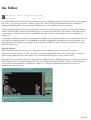
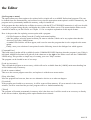
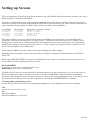
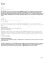
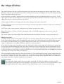
the Editor
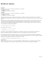
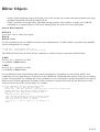
The Direct Mode working screen will appear, looking like this:
The Direct Mode screen has a bar of useful icons above a large window area where commands are entered and their
results displayed.
The [<E] button at the top-left of the screen is used to return to Edit Mode. This is also achieved by pressing the
[Esc] key.
The [WB] button at the top-right of the screen is used to go to the Workbench. If AMOS Professional has been
loaded from the Workbench, it will remain in memory, and you can return to AMOS Professional by pressing
[Amiga]+[A]. The [WB] button will have no effect if the CLOSE WORKBENCH command has been called from
one of your programs, as explained in Chapter 13.1.
To the right of the "DIRECT" identification panel is the [OUTPUT] icon. This is used to toggle the display of all
operations between the Direct Mode window and your program screen. If selected, operations will be performed in
the Direct Mode window, and the program display will remain untouched. To return to normal, simply select the
[OUTPUT] button again. Please note that only text output is permitted within this window.
The row of ten icons between the [OUTPUT] and [WB] icons are the equivalent of pressing one of the Direct Mode
function key pre-sets [Fl] to [F10]. Selecting one of these icons with the left mouse button is the same as pressing
the equivalent function key. Selecting a button with the right mouse button is the equivalent of pressing
[Shift]+[Function key].
04.01.06
the Editor
Here is a list of the pre-set commands called by these icons. Experienced AMOS programmers will already be
familiar with their meanings, and new users will be introduced to them in the following Chapters. The following
function key assignments are for Direct Mode only, and should not be confused with the operation of function keys
from Edit Mode.
Left Mouse Button (LMB). Right Mouse Button (RMB)
LMB LIST BANK
RMB SCREEN CLOSE
LMB DEFAULT
RMB SCREEN OPEN
LMB DIR
RMB WIND OPEN
LMB DIR$
RMB SCREEN CLOSE
LMB PARENT
[F1]
[Shift]+[F1]
[F2]
[Shift]+[F2]
[F3]
[Shift]+[F3]
[F4]
[Shift]+[F4]
[F5]
RMB BOB OFF: SPRITE OFF [Shift]+[F5]
LMB LOAD BANK
RMB FREEZE
LMB SAVE BANK
[F6]
[Shift]+[F6]
[F7]
RMB UNFREEZE
[Shift]+[F7]
LMB LOAD IFF
[F8]
RMB AMAL OFF
[Shift]+[F8]
LMB SAVE IFF
[F9]
RMB EDIT
[Shift]+[F9]
04.01.07
the Editor
LMB return a file's full path string [F10]
RMB SYSTEM
[Shift]+[F10]
The Direct Mode window can be moved around the screen by dragging it with the left mouse button, or by pressing
the [Ctrl] + [Up Arrow] and [Ctrl] + [Down Arrow] keys. The size of the Direct Mode window is changed by
dragging its bottom border, or by using the [Shift]+[Up Arrow] and [Shift]+[Down Arrow] keys.
You are reminded that the [Up Arrow] and [Down Arrow] keys are also used to recall up to twenty previous lines
entered in Direct Mode. Simply hit the [Return] key to execute any recalled line. The number of lines that can be
recalled may be changed from twenty to anything in the range of zero to 128, and this process is explained in
Chapter 13.1.
To end this examination of AMOS Professional Direct Mode, your attention is drawn to the prompt line at the lower
left of the Direct Mode Window. The AMOS Pro> prompt is highlighted, and marks the position at which your
typed instructions will appear. The prompt itself awaits your instructions, which will be executed as soon as you
press the [Return] key.
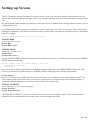
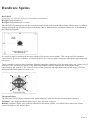
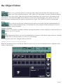
The File Selector
Please summon up the File Selector now. Simply go to Direct Mode and press [F10] on your keyboard.
Programs are stored on discs as "files", and each is given an individual file name. The File Selector is a means to
gain access to individual files, and Chapter 10.2 is devoted to all the aspects of files stored on disc.
The AMOS Professional File Selector is faster than its AMOS and Easy AMOS predecessors, it offers more features
and it happens to be a lot better looking! The physical size and positioning of the File Selector can be changed to
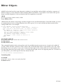
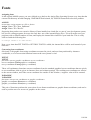
your own preferences and this is explained in Chapter 13.1. When the AMOS Professional File Selector is
summoned, it appears like this:
04.01.08
the Editor
Please note that a maximum of 10k is needed to open the AMOS Professional File Selector. If memory does not
allow for the File Selector to be opened, a simple input line will be displayed instead, inviting you to enter a file
name. If this very rare situation happens, type in the name of the file you wish to load or save, and press [Return].
The standard AMOS Professional File Selector features a window displaying the names of all the files stored on the
current disc. There is a slider bar to the right of this window, as well as a pair of Up/Down arrows, allowing you to
scroll through the file names. By using this slider, all available paths can be displayed, without the need to specify
path names.
On the right-hand side of the File Selector is a column of buttons offering the following facilities, from top to
bottom:
[OK]
This affirmative button informs AMOS Professional that you are satisfied with the current situation and dismisses
the File Selector, returning you to the current program. It can be used to save the current program to disc, after you
have typed in the new program name in the input line at the bottom of the File Selector. Whenever you click on
[OK], AMOS Professional automatically sets its current directory to the directory of the File Selector.
[Cancel]
Cancel your current operation by clicking on this button.
[Parent]
Because the hierarchy of individual files can get complex, it is sometimes necessary to negotiate a path through the
current directory. A full explanation of this subject is covered in Chapter 10.2.
[Devices]
This is used to call up a list of all devices. In other words, the available hardware items, such as disc drives.
[Assigns]
When this option is selected, only the current assigns are listed.
[Sort]
If this button is in the "on" position, files will be automatically sorted when they are read from the disc, and listed in
order. The File Selector will remember the setting of the [Sort] button when it is next called.
[Sizes]
If this button is "on", the size of each file will be displayed. This setting is also remembered when the File Selector
is subsequently called.
[Get Dir]
This button re-reads the current disc directory, and can be useful if the floppy disc has been changed.
04.01.09
the Editor
[Store]
The system works normally if this button is "off", but as soon as it is clicked "on", the directory is stored in
memory. If there is enough memory available, up to ten different directories may be stored with this facility. The
positions in the list are stored along with the list of files themselves, so that next lime you request a directory,
AMOS Professional will scan the list of stored directories and attempt to match any requested path names. If
successful, the directory is displayed instantly, and if unsuccessful, a normal search of the disc will take place.
Below this column of buttons, there is a small slider display indicating available memory. The small [X] button to
the right of this slider is used to erase the current directory from memory. Note that releasing the [Store] button will
erase all stored directories.
Please note that before available memory is exhausted, AMOS Professional will automatically "flush" stored
directories, freeing as much memory as possible.
You can move the File Selector to another position on screen by dragging the title bar with the left mouse
button.
The [Up Arrow] and [Down Arrow] keys can be used to scroll through the list of files.
The [Tab] key can be used to change the path or name of the edit zone.
To summon a new directory, either use the [Get Dir] button or press the [Enter] key.
If error messages are displayed in a small requester, they can be dismissed by a mouse click or by pressing
any key.
Because AMOS Professional stores directories in their most recent state, you should use the [Get Dir] option
to re-display a large directory that has not had time to be fully displayed when it was stored.
The amount of RAM used by the File Selector depends on the size of the screen and the number of files. File
selector routines require 2k, and each file requires its length plus ten bytes (so 100 files of 16 characters needs
3k.)
Saving and loading a program
Once you have created an AMOS Professional program, it can be saved onto disc using the [Save] option from the
[Project] menu, or by pressing [Amiga]+[S]. The File Selector will appear, and you can enter your file name, them
press [return] to save it onto the disc.
Programs are loaded using the same system. Select the [Load] option from the [Project] menu, or press [Amiga]+[L].
Alternatively, you can load a program into a brand new window using the [Open & Load] option, explained later.
Choose the name of the program to load by highlighting it in the File Selector window, then press [Return]. It's as
simple as that.
If your current program is too large for the current Editor window, a dialogue box will appear asking if you wish to
adapt its size. Selecting the [Yes] option will increase the memory to the minimum amount required for holding
your program. To add extra lines will prove impossible unless you make some deletions first. By pressing the [No]
option, a SET TEXT BUFFER operation will be called, setting the buffer area to the exact size required for the
current program. You can now increase the size of the buffer area as required.
04.01.10
the Editor
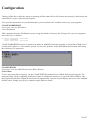
Autosave and Autoresume
As a default, you will be automatically prompted to save the results of your current programming session every 30
minutes. A separate Autosave dialogue box will be displayed for each window on screen. Pressing [Return] or
clicking on the [Yes] button will save your program to disc under its current file name automatically. If the program
has not been previously saved, the File Selector will be summoned inviting you to enter the new program name. The
time elapse between Autosaves can be changed to your own choice, using the configuration options detailed later.
The [Quit options] item from the [Config] menu allows the automatic saving of the current programming
environment to disc, whenever you leave AMOS Professional. This environment includes all current programs,
along with a complete list of currently open windows. Even the cursor positions are saved! This means that when
you return to AMOS Professional, your screen is exactly as it was, and you can re-commence your programming
session at the point from which it was left. This facility is intended for hard drive users, although it can be exploited
if you have an additional floppy disc drive, provided that you boot AMOS Professional directly, as opposed to from
the Workbench, and save your programs on the additional external floppy drive. Your start-up disc should be writeenabled to allow AMOS Professional to load in this way.
The AMOS Professional Editor Menus
The following section of this Chapter contains a comprehensive explanation of every option available from the
AMOS Professional Editor Menus. The menus are examined in the order that they appear, from left to right, when
the right mouse button is pressed to reveal them. All menu headings, menu options and sub-menu items that can be
selected via the mouse are shown between square brackets. Where selections can also be made via the keyboard, the
keys are also shown in square brackets. A function key appears like this [F1], and a key in the numeric keypad
appears like this [N1]. For example:
[About AMOS Professional]
This indicates that the menu option is selected by highlighting it with the mouse pointer, and then releasing the
mouse button.
[Run] or [F1]
This means that the option can be chosen via the mouse, or it can be summoned by pressing a single function key.
[Save As] or [Amiga]+[Shift]+[S]
In this case, the option may be selected using the mouse, or by pressing the indicated combination of keys together.
Main menu headings are shown in large bold type, with their options printed in smaller bold type. Where an option
has its own sub-menu, the items in the sub-menu are shown in standard type, as follows:
Config
Main menu heading
[Set Editor] Menu option
[Setup]
Item in option sub-menu
04.01.11
the Editor
Here is the list of the AMOS Professional Editor Menu options.
AMOS
The [AMOS] menu appears in the top left-hand corner of the screen, and provides information and control of
accessory programs via the following options:
[About AMOS Professional]
This displays a title box, and indicates the number of any extension files that have been installed into AMOS
Professional, such as the music extension or picture compactor extension.
[About Loaded Extensions]
This option displays detailed information about all extensions that are currently loaded. Each extension has its own
title screen, and the list can be examined via the [Prey] and [Next] buttons. Click on [Cancel] to return to the Editor
Screen. You are free to create your own extensions for use with the AMOS Professional system, and more
information on this topic can be found in Appendix D of this User Guide.
[Load Accessory]
When this option is selected, a file selector is opened, allowing any AMOS Professional program to be loaded as an
accessory. Unlike normal programs, accessories are hidden away in memory, and do not need their own window in
order to work. Accessories can be run by selecting their name from this [AMOS] menu list, and if this is done, the
following options are presented:
[Run]
This runs the accessory immediately, without affecting the existing programs.
[Edit]
Use the [Edit] option to copy the selected accessory into a new window, allowing it to be edited directly on screen.
[New]
This erases the accessory from memory, and removes its reference from the AMOS Professional menu.
Please note that the last three options may not be assigned to a keyboard short-cut. If you want to install the
program as a normal menu item, the [Set Program to Menu] option should be used instead. Please refer to the
[Config] main menu for details.
[New All Accessories]
This option is used to delete all accessories from memory. You will be asked to confirm your action before the
deletions are executed.
[Quit]
This quits AMOS Professional completely, and returns you directly the Workbench or CLI.
04.01.12
the Editor
A number of features are provided to save vital data to disc automatically before you quit AMOS Professional, and
these are explained near the end of this Chapter in the [Config] Main menu section.
Project
This menu provides all of the options that are used to manipulate program listings, and existing AMOS and Easy
AMOS users will find some familiar commands here.
[Run] or [F1]
This runs the AMOS Professional program that is in the active window.
[Test] or [F2]
This triggers a check through your program listing, searching for any syntax errors. If a problem is encountered, a
report is given on the screen.
[Indent] or [F3]
Use the automatic indentation system to make program listings easier to read. Extra spaces are added at the
beginning of all lines that belong to particular sorts of routines, and similar indenting is shown throughout the
example programs printed in this User Guide.
[Monitor] or [F4]
See how your programs run and operate under the AMOS Professional Monitor. Chapter 12.1 explains all the
monitor's operations in details.
[Open New] or [Amiga]+[Shift]+[W]
This is used to open a completely new window on the editor screen.
[Open & Load] or [Amiga]+[Shift]+[L]
This is a fast method of loading a program directly into a new window. After it opens the window, the program is
loaded via a standard File Selector.
[Load] or [Amiga]+[L]
This will load a program into the current window, and any existing contents of this window will be completely
erased. If the new program is larger than the available editor buffer space, the following dialogue box appears on
screen:
Text Buffer too small. Adapt size?
If you click on the [YES] response, the size of the buffer will be set to the absolute minimum needed to hold the
program, and it should only be used if you do not intend to make any further changes, because the buffer will be
filled to capacity.
By selecting [NO], the [Set Text Buffer] option will be called from the [Editor] main menu, allowing you to expand
the buffer to any required value.
[Save] or [Amiga]+[S]
This option is used to save your AMOS Professional program to disc. If there is no existing filename for the
program, a request is made to enter a new name via a standard File Selector. If the name already exists, the program
will be copied into the original file immediately.
04.01.13
the Editor
[Save As] or [Amiga]+[Shift]+[S]
This saves the existing program under a new name. A selector will be displayed on screen to allow the destination
file to be selected.
[Close] or [Amiga]+[Shift]+[Q]
When this option is chosen, the active window is closed down and its contents are completely erased. If the window
has been set up using the split-screen option, the original source listing will remain intact.
[New] or [Amiga]+[Q]
Using this option will delete the current program, leaving its window in position, ready for further editing.
[Hide] or [Amiga]+[H]
This closes the present screen window, and hides the program into memory as an accessory. This program may now
be called from the [AMOS] Main menu heading directly.
[Hide]
can only be used if there are at least two windows on the screen, and the last window on display cannot be hidden. If
a split screen is hidden, all splits are erased and the window is then hidden.
[Print] or [Amiga]+[P]
If there is an active printer connected to your Amiga, this option can be used to list the current program directly onto
paper.
[Merge] or [Amiga]+[M]
With this option you can merge in from disc another file that was previously saved as an normal AMOS Professional
program. This allows you to merge in libraries of routines when you need them.
[Merge Ascii] or [Amiga]+[Shift]+[M]
This merges an Ascii text file into the current program listing.
For large listings, the merging-process can take a few minutes to complete, so patience may be needed.
[Check 1.3] or [Amiga]+[Shift]+[I]
Calling all AMOS users of version 1.3! This option performs an automatic test on your AMOS Professional
programs to see if they are compatible with AMOS v1.3. A search is made for any commands that are not available
to AMOS v1.3, as well as any memory banks with an index number above 16. A message will be generated
informing you whether or not your AMOS Professional program can run under AMOS v1.3.
The Editor will save the correct header automatically. If it is compatible with AMOS v1.3, that header will be used,
otherwise the AMOS Professional header will be employed.
04.01.14
the Editor
[Information] or [Amiga]+[I]
This option calls up a useful information panel, where details of the current programming session are summarised
like this:
AMOS Pro Editor Information
Free Chip Ram:
(the amount of available memory for sound and graphics)
Free Fast Ram:
(available space for listings, menu banks and dialogue
routines)
About current program
Text Length:
(memory assigned to the editor window)
Bank length:
(memory used by your banks)
Number of visible lines: (the size of the program in lines)
Number of instructions : (the total number of instructions in the program)
Editor
The [Editor] main menu heading provides the gateway to all of the vital editing commands. It is divided into a set of
sub-menus, each of which provides a group of important related options.
[Procedures]
This displays a small sub-menu that contains all of the options needed to fold and unfold procedure definitions. The
use of procedures is described in detail in Chapter 5.5.
[Open/Close] or [F9]
This option is used to fold or unfold the single procedure which is currently under the cursor. After this has been
done, the whole program is checked for errors, and if a problem is encountered, an appropriate message is displayed
on screen, and the operation is aborted. If all is well, a closed procedure will be opened to reveal all of its original
contents, or an open procedure will be folded away and be replaced by a single line containing nothing but the
procedure's name.
Closed procedures can be cut and pasted as usual, but they cannot be deleted using the editor keys. To remove a
folded procedure, the [Cut] option should be used.
[Open All] or [Amiga]+[Shift]+[O]
Use this option to open all currently folded procedures, displaying the current program in its original glory.
[Close All] or [Amiga]+[Shift]+[C]
This folds all procedures into memory, leaving a single procedure name line for each one.
[Insert Program]
This option is used to load a machine language routine directly into the selected procedure. This procedure will now
be closed and its existing contents will be replaced by the new code. Please see Appendix A for full details.
[Windows]
The windows menu is used to set the size and position of editor windows. Here is a list of the menu items:
04.01.15
the Editor
[Previous] or [F6]
This moves the cursor up to the window above the currently active window.
[Next] or [F7]
When this option is selected, the cursor is positioned over the next window on the display.
[Flip Size] or [Amiga]+[N5]
This reduces the window to a single title line, keeping it displayed and out of the way.
[Split] or [Amiga]+[Shift]+[V]
When a new window is opened on the current program via this option, it can be freely positioned anywhere in the
listing. This allows several different sections of the program to be displayed on screen simultaneously.
Please note that this option does not create a separate copy of the program listing in memory, it simply splits a
single listing between a number of different windows. This means that any changes will be shown on all of the
relevant windows as soon as they are made.
The [Split Screen] option can be de-activated by the [Close] command in the [Project] menu, explained earlier. It
can also be turned off with the [Close Window] icon on the window title.
The window title lines will change automatically to reflect the new mode, with the "Edit" message to the left of the
filename being replaced by "Split".
[Link cursor] or [Amiga]+[C]
This links the movements of the text cursor between any two windows. This means that whenever one of the
selected windows is scrolled through, the other will keep in step.
The source window is the window which is currently active, and a request will be made to select the destination
window as soon as [Link cursor] is selected. To make your choice, move the mouse pointer over a window and click
once on the left mouse button. The source and destination windows are now linked together. To separate them,
trigger [Link Cursor] again and click on the source window.
This option is very useful for copying data from one program to another, as well as for comparing two programs,
line by line.
[Move up] or [Amiga]+[Shift]+[N8]
[Move down] or [Amiga]+[Shift]+[N2]
These two options move the top of the current window up or down in units of eight pixels, which is one screen line.
It is also possible to position the window directly, by dragging the mouse pointer on the window title with the left
button.
[Expand] or [Amiga]+[N2]
This moves the bottom border of the window eight pixels downwards, increasing its size by one screen line.
04.01.16
the Editor
[Reduce] or [Amiga]+[N8]
To reduce the bottom border of the window, use this option to position it higher by one screen
Macros
The [Macros] menu allows a whole string of editor commands to be assigned to a single key-press.
[Enter a New Macro] or [Ctrl]+[M]
After selecting this option, you will be asked which key-press is to be allocated to the new Macro. This can be a
single character or a combination of keys that are to be pressed together. Macros work by referring to the "scan
code" of keys rather than the actual character value. This means that any key or combination of keys can be
assigned independently, including the keys from the numeric keypad, providing that the following rules are obeyed:
Other Macro definitions may not be included. They will be completely ignored!
Each Macro definition can hold up to 400 key presses.
Menu short-cuts can only be used if they do not call up a dialogue box, so the keys allocated to [Search New]
are not available, but the [Search Next] and [Search previous] keys will work without problems.
If your key combination has been previously assigned to a menu item, the existing short-cut keys will be deactivated and the new Macro definition will take priority.
Once a new Macro has been defined, click on a mouse button to save it into memory. To keep Macro definitions,
they can be saved directly onto disc using the [Save Macro] option explained below.
[Delete One Macro]
Simply select the Macro to be deleted by pressing its key combination. It will then be deleted from memory. This
memory space will now be released to the main AMOS Professional system.
[Delete All Macros]
This option is used to erase all Macro definitions in a single operation.
[Load Macros]
This loads a named Macro file from disc.
[Load Default Macros]
Use this option to load the AMOSPro.Macros file from the APSystem folder.
[Save Default Macros]
This saves all defined Macros into a special file on disc, named AMOSPro.Macros. In future, whenever AMOS
Professional is run, the saved Macros will be loaded instantly.
If necessary, Macro definitions can be saved automatically, whenever you leave AMOS Professional. This process is
detailed below, under [Quit Options] in the [Config] Main Menu heading.
04.01.17
the Editor
[Save Macros]
When this option is called, a file selector is opened with a request for a filename to be given. All Macro definitions
will be saved in the chosen file onto disc. This can be used to create special Macro lists for particular programming
tasks.
While working on a very long program, a great deal of time can be wasted moving back and forth through the
listing. The next selection of menu options is used to control up to ten markers, which allow a specific position in
the listing to be marked and saved.
[System Marks]
The first, second and third Marks are automatically loaded with your last three cursor positions, so if you move to a
new label, or execute a [Search/Replace] operation, for example, you can jump back to the previous location
instantly.
The Mark system works like a stack, and every time you move to a new location in the program listing, the position
of the cursor in added at the bottom of the stack, with the oldest Mark being discarded from the top of the stack.
When the [System Mark] option is chosen, the following simple sub-menu is presented:
[Goto 1] or [Ctrl]+[N1]
[Goto 2] or [Ctrl]+[N2]
[Goto 3] or [Ctrl]+[N3]
These three options are used to jump directly to the last, second to last and third from last cursor positions.
[User Marks]
These marker points can be user-defined anywhere in the current program. The Marks are set by holding down the
[Ctrl]+[Shift] keys, and pressing a key from [4] to [9].Once a Mark has been set in this way, it can be jumped to by
holding down the [Ctrl] key and pressing the appropriate number key.
The [User Marks] option presents two lists of Mark numbers from [4] to [9]. By highlighting one of these items, an
additional menu is presented allowing you to [Set] or [Goto] the chosen Mark.
[Cursor Move]
This option is provided to show a representation of the movement keys from within the menu. Once you have
become familiar with the various key combinations, it is probably faster to control movements directly from the
keyboard. Here are the various items in this menu:
[Goto Line Number] or [Amiga]+[G]
This is used to move the cursor directly to a specified line, and a dialogue box is presented ready for the line number
to be entered. The lines in the listing are counted from the top, starting at line number one. Closed procedures are
treated as a single line. Press [Return] or click on the [OK] button to jump to the specified line.
04.01.18
the Editor
[Previous Label] or [Alt]+[Up Arrow]
This is used to jump directly to the previous label or procedure definition in the program listing.
(Next Label] or [Alt]+[Down Arrow]
Use this option to jump to the next label or procedure definition in the listing.
[Text Top] or [Ctrl]+[Shift]+[Up Arrow]
This will display the program listing from the very first line.
[Page Up] or [Ctrl]+[Up Arrow]
Scroll the program listing up by one window page, using this option.
[Page Top] or [Shift]+[Up Arrow]
This moves to the top of the current window.
[Page Bottom] or [Shift]+[Down Arrow]
Jumps directly to the bottom of the current window.
[Page Down] or [Ctrl]+[Down Arrow]
Scrolls the program listing down by a single window page.
[Text Bottom] or [Ctrl]+[Shift]+[Down Arrow]
Use this option to move directly to the last line in the program listing.
[Line Start] or [Ctrl]+[Left Arrow]
jump to the beginning of the current line in the listing.
[Word Left] or [Shift]+[Left Arrow]
This is used to move to the previous word in the program listing.
[Word Right] or [Shift]+[Right Arrow]
The cursor is placed over the next word in the program listing.
[Line End] or [Ctrl]+[Right Arrow]
This option moves the cursor to a position immediately after the last character in the current line.
[Insert/Delete]
Here is a list of the options available for inserting and deleting in program listings:
[Clear Line] or [Ctrl]+[Q]
This is used to delete the entire line in which the cursor is currently positioned, leaving a blank line in its place.
[Delete to S.O.L.] or [Ctrl]+[Backspace]
This erases all characters from the current position of the cursor backwards to the Start Of the current Line.
04.01.19
the Editor
[Delete Left Word] or [Shift]+[Backspace]
The word to the immediate left of the cursor is deleted by this option.
[Delete Right Word] or [Shift]+[Del]
This erases the word in the current line immediately to the right of the cursor.
[Delete to E.O.L.] or [Ctrl]+[Del]
Use this option to erase all characters from the current cursor position forwards to the End Of the current Line.
[Delete Line] or [Ctrl]+[Y]
This completely erases the current line, and the program listing scrolls upwards one line to fill the gap.
[Insert Line] or [F10]
This option is used to insert a blank line at the present position in the program listing.
[Tab Right] or [Tab]
Move the cursor right, to the next Tab setting.
[Tab Left] or [Shift]+[Tab]
This is used to move the cursor one position left to the previous Tab setting.
[Set Tab] or [Ctrl]+[Tab]
This option is used to set the distance in characters between successive Tab stops.
[Set Text Buffer] or [Amiga]+[Shift]+[T]
This is the option which is used to change the size of the memory area assigned for program listings. Each window
has its own separate text buffer, which can be set independently.
A dialogue box appears, allowing a new text buffer size to be entered directly. If the memory allocation is increased,
the new space can be used immediately from the Editor. However, if the new memory setting is smaller than the
previous value, the existing contents of the window will be lost!
[Undo] or [Control]+[U]
This powerful option is used to erase every character edit, movement and block operation that has been created in
the current editing session. You simply keep calling Undo to work back through the changes you made before
calling Undo.
A call to CLOSE EDITOR or the running of a program will clear all the Undo memory store.
[Redo] or [Control]+[Shift]+[U]
As a fail-safe against a hasty undoing operation, this option is provided to re-write everything that has been erased
by an [Undo].
04.01.20
the Editor
Block
The [Block] Main Menu heading reveals all of the cut-and-paste commands which enable the fast copying,
movement and deletion of blocks of a program listing. Here are all the options:
[On/Off] or [Ctrl]+[B]
Use this option to toggle between the Block mode and the normal Editing mode. The same change is achieved by
double clicking on the left mouse button.
As soon as the Block mode is entered, the text cursor is replaced by a solid block cursor, at the current position.
A Block is set by holding down the left mouse button, and dragging the cursor to the desired destination point.
Alternatively, the dimension of the Block can be set directly from the keyboard using the [Up Arrow] and [Down
Arrow] keys. When a Block is set, it will be marked by inverse video highlighting.
Unlike the original AMOS system, AMOS Professional Blocks can be marked out in units of a single character, so
the beginning and end Block positions should include whole command words.
Blocks can be freely copied between different windows, by grabbing a Block into memory from the source window
with [Store] or [Ctr1]+[S], and then clicking in the relevant line of the destination window followed by [Paste] or
[Ctrl]+[P].
[All Text] or [Ctrl]+[A]
This selects all text in the current file, ready for block operations.
[Store] or [Ctrl]+[S]
This option is used to store the marked Block into memory, ready for a subsequent [Paste] operation. The
highlighting of the Block will be removed, and you will be returned to Editing mode.
[Cut] or [Ctrl]+[C]
This grabs the marked block into memory, and cuts it out of the program listing completely.
[Paste] or [Ctrl]+[P]
To insert an exact copy of the Block at the current cursor position, use this option for a Block that has been saved
with a [Store] or a [Cut] option.
[Forget] or [Ctrl]+[F]
This option is used to erase a stored Block from the computer's memory.
[Print] or [Ctrl]+[Shift]+[P]
If a printer is connected and ready to print, this option is used to list the Block directly onto paper.
04.01.21
the Editor
[Save] or [Ctrl]+[Shift]+[S]
This will save the Block as a normal AMOS Professional program. It is vital that the start and end points of the
Block are perfectly aligned, to avoid including nonsense in the final program.
[Save Ascii] or [Ctrl]+[Shift]+[A]
This option saves the Block as an Ascii file. This allows it to be edited by a commercial text editor.
Search
The [Search] menu provides all of the options that are used to search through program listings, hunting for specific
strings of characters. Once located, these strings can be automatically replaced by alternative characters. Users of the
original AMOS and Easy AMOS systems will find several new features here.
A Search dialogue box is called up by the relevant option, and this is used to type in the string of characters to be
sought. The search string can be up to 32 characters long and can include any combination of characters, words or
instructions.
Normally all searches will be made forwards in pursuit of exact matches of the given characters, but by selecting
various options that are explained below, this can be changed. Apart from menu options, there are two settings
available from the dialogue box, as follows:
[Backward]
If ticked for selection, the search will start from the current cursor position backwards through the program listing.
[Upper Case = Lower Case]
If ticked, this ignores any distinction between upper and lower case letters in the search string.
After the characters have been typed in, and any options selected, the search is launched by pressing the [Return]
key or clicking on the [OK] button.
If the search is successful, the cursor will be positioned over the first character in the target string, otherwise a "Not
found" message is displayed.
Current search preferences are kept, so that next time a search or replace operation is carried out in the programming
session, your selected options will be ready for use.
[Search New] or [Amiga]+[F]
This searches through the program for the first occurrence of the selected string of characters, starting from the
current cursor position.
[Search Next] or [Amiga]+[N]
Use this option to search for the next occurrence of the string, after a [Search New] or [Replace] operation.
04.01.22
the Editor
[Search Previous] or [Amiga]+[B]
This will search backwards through the listing until an example of the target string is found, or the beginning of the
program is reached.
[Replace New] or [Amiga]+[Shift]+[F]
This replaces any string of characters or any AMOS Professional instruction with your given text. The dialogue box
for this option contains two editing zones:
The target characters that are to be located and then replaced are to be found in the Search string. This will be the
same as any previously called [Search] operation, or a new string can be specified. The Replace string holds the text
that will be substituted in place of the original characters. Click on the appropriate zone using the left mouse button,
or flick between the Search and Replace strings using the [Tab] key.
As well as the [Backward] and [Upper Case = Lower Case] options, two more settings are available when a Replace
operation is chosen.
[All Occurrences]
This automatically replaces every instance of the target string with the new characters. Obviously this can be a
drastic operation, so you will be asked to confirm your wishes before they are obeyed.
[All in Marked Block]
This restricts the Search and Replace operation to all instances of the target characters within the currently
highlighted Block.
Once the strings have been set, a Replace operation is commenced by pressing [Return] or triggering the [OK]
button. After a successful Replace operation, the cursor is positioned immediately after the amended text. If the
search fails, a "Not found" report will be given in the title line.
[Replace next] or [Amiga]+[Shift]+[N]
Use this option to scan the program listing for another example of the search string. If this is successful, the cursor is
placed immediately after the replaced text.
[Replace Previous] or [Amiga]+[Shift]+[B]
This checks backwards through the program listing, and replaces the targeted characters with the replacement string
entered by a [Replace New] option.
Config
The AMOS Professional editor can be totally re-configured, allowing you to tailor it precisely to your own needs
and preferences. All of the keyboard assignments can be changed, all of the system messages may be freely
customised and you can even assign existing menu items directly to your own programs and call them straight from
the screen!
This sort of feature allows you to use sophisticated techniques with the utmost simplicity, making your programming
truly professional.
04.01.23
the Editor
[Show Keys] or [Amiga]+[K]
As a default, all menu options have their equivalent keyboard commands displayed alongside. This option is used to
remove these explanations from the menus. Keyboard short-cuts can still be used as normal, even if the constant
reminders of their settings are removed. A tick mark is added against this item to show that it has been selected.
[Insert Mode] or [F8]
This toggles the Editor between Insert and Overwrite mode, as explained earlier in this Chapter.
[Sounds]
Sound effects may be used by the AMOS Professional Editor, and this option loads a list of audio samples from the
AMOSPro.Samples folder, providing accompanying effects when various options are called up.
To turn these sound effects off, simply click on the [Sound] option again. The creation of your own sound effects is
dealt with in Chapter 8.2.
[Set Key Short-cut]
Most menu items can be assigned to an equivalent combination of control keys. This allows menu commands to be
accessed directly from the keyboard for extra speed.
AMOS Professional is equipped with its own pre-defined set of keyboard options, but these can be changed from
the Editor at any time. Experienced AMOS programmers and users of commercial word processing packages may
want to change the AMOS Professional layout to something more familiar, and any new definitions can be saved as
part of the configuration file.
This means that your favourite keyboard settings will be available automatically, every time you begin a
programming session.
Setting a keyboard short-cut is extremely simple. Here is the procedure:
Call the [Set Key Short-cut] option from the [Config] menu.
Select any target menu option. This can be any option except accessory items that are assigned to the [AMOS]
Main menu heading.
Enter your keyboard short-cut directly from the keyboard. This can comprise a single key press, as well as
any combination of the [Shift], [Ctrl], [Alt], [Amiga], [Function] or [Cursor Arrow] keys.
Remember that AMOS Professional uses the scancode of keys, and not their Ascii values. This means that the keys
in the numeric' keypad can be assigned different functions from the standard number keys. If a selected combination
of keys is already in use, you will be asked to confirm your choice before proceeding. A response of [YES] will
erase the original short-cut, and replace it with your new setting.
Obviously, if these settings are played with casually, the resulting confusion may be difficult to rectify. If this
happens, reload the AMOS Professional standard settings from the "AMOSPro.Configuration.Backup" file located
within the "Extra_Configs" folder on the "AMOSPro_System" disc.
04.01.24
the Editor
[Set Program to menu]
Ths option allows any menu option to be replaced with a simple call to an AMOS Professional program. This can
be loaded from disc automatically, and executed every time the appropriate menu option is called. Alternatively, the
program can be permanently installed in memory, ready for instant use.
If the program has been defined as an Editor Accessory with the SET ACCESSORY instruction, it will even be able
to call up a program listing directly, and display the results on the Editor screen. This means that the Editor can be
extended as much as you like! Please see Chapter 13.1 for a complete explanation of this superb feature.
Here is the procedure for replacing a menu option with a program:
Call [Set Program to Menu] from the [Config] main menu heading.
After the prompt, select the menu item that you want to redefine, which can be any option other than the
Accessory list in the [AMOS] menu.
A standard File Selector will now appear, and is used to enter the program that is to be assigned to the menu
option.
Finally, enter your selection of run options from the following items in the dialogue box which appears:
[Command Line:]
This holds some text that will be available from the COMMAND LINE$ function when the program is run. If this is
left blank, AMOS Professional will grab all of the characters to the right of the Editor cursor into the COMMAND
LINE$ string. This provides a simple way of creating your own "Help" routines.
The program can be loaded in one of two ways:
[Load As Accessory]
This will load the program as an accessory, which will not be available from the [AMOS] main menu heading, but
will be hidden away in memory.
[Load in current window]
This saves the current program onto disc, and replaces it with the new menu routine.
[Keep After Run]
After the program has been run, there are two alternative choices as to what can happen:
[Un-ticked]
If the program was loaded as an accessory, it will be removed from memory. If it was entered via the current
window, it will be erased and the previous program will be re-loaded automatically.
[Ticked]
The program will remain permanently in memory after it has been run. It will be stored as an accessory or directly
in the current window, depending on the option that has been selected.
04.01.25
the Editor
[Quit Options]
This menu controls what happens when you choose to quit the Editor. A large dialogue box is displayed, offering
these possibilities:
[Confirm Quit]
If this option is ticked, AMOS Professional will always ask for confirmation before allowing you to quit.
[Save Configuration]
If the Editor configuration has been changed during the current editing session, these changes will be saved directly
into the "AMOSPro.Configuration" file in the APSystem folder, before quitting.
[Save Macros]
This forces any new Macro definitions to be saved onto disc whenever AMOS Professional is quit.
[Auto-resume]
If this option is selected, all programs in memory will be stored on disc automatically, before allowing you to leave
AMOS Professional. The next time AMOS Professional is loaded, it will be restored to the exact state in which it
was left. This important facility allows the AMOS Professional programmer to re-commence work at the exact point
and in the exact state of the last working session!
[Autosave]
The Autosave feature provides a regular prompt to remind you that all listings are to be saved to disc. A dialogue
box is displayed at regular intervals for each program in memory.
Selecting the [YES] button saves a program to disc, under its present filename. If [NO] is chosen, the next program
in the list is moved to.
The [Autosave] option offers a choice of the delay interval between each reminder to save your programs, set in
minutes. To turn the reminder system off, simply enter a value of zero.
[Set Editor]
Use this option to reveal the following sub-menu, for setting your own preferences.
[Setup]
The Editor set-up can be changed via the simple dialogue box presented by this option. The AMOS Professional
configuration is fully dealt with in Chapter 13.1.
[Colour Palette]
The On Screen colours can be set to your desired requirements when you click on this menu item.
04.01.26
the Editor
[Menu Messages]
This option allows you to change the default text of the menu messages to your own wording, or into a non-English
language. Menus are explained in Chapter 6.5, and the menu editor is examined in Chapter 13.3.
[Dialog messages]
Similarly, the wording of the AMOS Professional dialogue boxes can be changed. The whole of Section 9 of this
User Guide is devoted to dialogue boxes, buttons and icons, and Chapter 13.7 explains how to create your own
resources.
[Test-Time Messages]
The information messages and error messages that appear when a program is tested can also be changed. A full list
of these messages is contained in Chapter 12.3.
[Run-Time Messages]
Similarly, the messages that are called up when a program is run may be changed to your own wording. These are
also listed in Chapter 12.3.
[Load Configuration]
When this option is selected, a named configuration file is loaded, which holds all of your options for Editor
settings.
[Load Default Configuration]
This option loads a file named AMOSPro.Configuration from the APSystem folder, and the Editor is returned to its
pre-set default settings.
[Save Default Configuration]
Use this option to save your own current settings as the default settings, into the default AMOSPro.Configuration
file. These settings will then be presented whenever AMOS Professional is run.
[Save Configuration]
this item is used to save the current configuration, ready to be loaded with [Load Configuration].
[Set Interpreter]
Selecting this option will call up a special AMOS written Accessory which allows you to define many special
features of the AMOS Professional Interpreter. See Chapter 13.1 for further details.
User
The [User] Main Menu heading presents the options that are used to create your own menu entries in the AMOS
Professional Editor. These entries can be assigned to any AMOS Professional program, and the selected program
will be loaded and run whenever the assigned option is selected. Please see the SET ACCESSORY command for
details of .how to define Editor Accessories, which can access the current program directly.
04.01.27
the Editor
[Add Option] or [Amiga]+[U]
When this option is selected, a dialogue box appears asking for the name of the new option to be inserted at the first
blank position in this [User] menu. The new name can contain up to 16 letters, and there is a maximum of 20
available options.
After the new name has been typed in, you can assign a program to the new option, using the [Set Program to Menu]
command, which is called automatically during this procedure. The new menu option can now be selected with the
mouse, and the associated program file can be chosen from disc. Finally, the [Set Key Short-cut] feature is
presented, allowing a keyboard equivalent to be selected immediately.
[Delete Option] or [Amiga]+[Shift]+[U]
This removes an option from the [User] menu. After selecting this feature, you will be asked to choose an option to
be deleted, using the mouse.
Help
Chapter 4.2 provides a detailed examination of the AMOS Professional Help system. The [Help] menu offers a list
of topics for which additional help is directly available. Select the item that you need help with, and an instant
explanation will be provided on screen.
[Help] or [Help key]
Use this to call up a quick definition, explanation and syntax example of any AMOS Professional instruction at the
current cursor position. The program cursor should be over the first character of the instruction with which you need
assistance.
[Help Menu]
This calls up the Main Menu of the AMOS Professional Help system, which is detailed in Chapter 4.2.
04.01.28
Help
This Chapter explains how AMOS Professional provides detailed on-screen help, co every aspect of the system and
your programming.
The User Guide is provided to explain all the features of AMOS Professional in detail, and to act as your instructor,
but a large book can never offer the instant help made possible by a computer program. AMOS Professional has
been designed to be as friendly as possible, and it harnesses the power of the Amiga itself to provide you with
interactive Help in your programming.
Calling for Help
Help is available at the touch of a button, whenever you are in edit mode. Simply press the [Help] key, it's as
obvious as that! Alternatively, click on the [H] icon at the top of the Edit Screen.
An additional list of Help options is also revealed by holding down the right mouse button, dragging the mouse
pointer to the [Help] menu, and selecting one of the pre-set headings. To start with, select the [Main Menu] option
from the [Help], menu, or simply press the [Help] key, or click on the [H] icon. In all cases, the Main Menu will
appear in a special Help Window.
The Help Window
Whenever [Help] is summoned, the AMOS Professional Help Window is flicked onto the screen. If it obscures your
listing, it can be repositioned by dragging the title bar up and down. All options are selected via the left mouse
buttons. At the left-hand side of the title bar, there is a [Close] button, to return you to the Edit screen.
On the right-hand side of the bar there are three simple options:
[Prev Page]
Click on this to reveal the previous page that was called during the helping process.
[Main Menu]
This option summons the Help system's Main Menu on screen.
[Print]
When this option is selected, you will be requested to check that your printer is ready to receive the words of
wisdom offered by the Help system. Simply click on [Ok] to obtain a printed copy of the current Help text.
On the right-hand side of the Help window there is a vertical slider bar and a pair of up/down arrows, enabling you
to scroll through the Help text.
The Main Menu
Using the AMOS Professional help system is completely straightforward, extremely simple, and incredibly
powerful!
04.02.01
Help
The Main Menu presents a series of sub menus, as follows:
Main Menu
Using Help
Editor
Direct Mode
Syntax conventions
Basics of AMOS
Screen control
Object control
Latest News
Audio
AMOS Interface
Input/Output
AmigaDos
Debugging
Machine code
Tables
Please note that this Menu may not appear exactly as in this User Guide listing, because we may have added more
information since going to print.
If you need assistance with any of these topics, simply select one.
Summoning direct Help during programming is explained later. Please select the [Basics of AMOS] option now, to
reveal a more detailed list of Help topics.
Sub-menus
As soon as an item is triggered by the left mouse button from the Help system Main Menu, a selection of related
topics is revealed. Any of these new headings can now be selected as before. In the case of the [Basics of AMOS]
option that you have just selected, they range from [The Bare Bones] to [Memory Banks]. Please select the [Text]
option that is on your screen now.
As you have probably guessed, all of the AMOS Professional features relating to [Text] are now displayed on screen.
Please select [Print] for a demonstration of instant Help. Not only will this command be explained in the form of
text on your screen, you will also be invited to click on the highlighted instruction [Print] and be treated to an instant
demonstration program!
There is so much electronic Help on offer, that this User Guide may seem redundant! Please keep reading anyway.
Summoning Help directly
In the early stages of AMOS Professional programming, before you become completely familiar with all the
features, it is all too easy to loose track of the precise format of every command. It can be very frustrating to consult
this User Guide in the middle of programming, and even using the various Help menus may break your
concentration. To make programming as painless as possible, Help can be summoned directly from your program
listings!
To receive instant help on any command directly from the Editor, either type in the instruction that you are not sure
about, or go to an instruction that is already in your program, and position the program cursor over the first letter of
that word. Now press the [Help] key or click on the [H] icon for instant assistance.
04.02.02
Help
Additional help
There is a complete range of additional help features available to the AMOS Professional programmer. Here is a
brief introduction to each of them.
Error Messages
If AMOS Professional encounters any problems with your listings, a wide range of helpful messages is available to
pinpoint the error. These error messages appear in the Information Line Hear the top of the Edit Screen, and they
fall into three main categories. Editing messages can appear while you are in the process of editing your programs,
such as "Line too long". Program messages like "FOR without matching NEXT" may be displayed when you [Test]
your work, a lid the program cursor will try to pinpoint where the problem is lurking in your listings. Run-time
messages come complete with their own number code, and they spotlight errors encountered while your program is
up and running.
A full list of these error messages can be found in Chapter 12.3, along with an explanation of what they mean, and
how to deal with the problem. Errors can usually be "trapped", and Chapter 12.2 is devoted to this sport.
The AMOS Professional Monitor
This feature is used to get inside your programs, examine any AMOS professional routine, discover exactly what is
happening, why it is happening and make a full report on screen. The Monitor not only offers help, it provides an
instant diagnosis! All is explained in Chapter 12.1.
Continuing Support
It has always been our policy to provide as much help and support to AMOS users as possible,and AMOS
Professional programmers are offered this assistance too. Future Support is dealt with in Appendix I, at the back of
this User Guide, and you may well want to join the network of world-wide clubs and groups offering a huge range
of help and support to AMOS Professional programmers. The services of the AMOS PD Library are detailed in
Appendix H.
04.02.03
the Bare Bones
Ths Chapter provides you with the bare bones that support AMOS Professional programming. These bones are used
to build program skeletons, and you need to understand what they do and how they work before adding the lifeblood, the muscle-power and the brain-control that endow a program with its own life.
If you are an experienced programmer, you will already be familiar with these bare bones, and you can safely skip
through most of this Chapter.
AMOS Professional is designed to provide you with the easiest and most convenient way of controlling all your
programming needs, and even though it provides very powerful programming features, difficult concepts and terms
are avoided wherever possible. This section begins with one of the simplest concepts in computing, known as
"strings".
Strings
A "string" is a number of characters strung together. A set of quotation marks is placed at either end of the string to
hold it together and keep it separate from the rest of the program. Each string is also identified by its own name, so
that it can be called up by that name, and used elsewhere in the program. The "dollar" character $ is attached to the
end of every string name, to mark the fact that this name refers to a string. On UK Keyboards, quote marks are
typed in by pressing the [Shift] and [2] keys together, and the $ character is typed with [Shift] plus [4].
Characters in a string can be letters, numbers, symbols or spaces. The following example creates a simple string
named A$, and it is defined by letting the name of the string equal the characters enclosed in quotes, like this:
E> "AMOS Professional"
Print A$
Here is another example, using three different strings:
E> A$="AMOS"
B$=""
C$="Professional"
Print A$+B$+C$
Strings are extremely useful, and they can act on their own or work together, as that last example demonstrated. Try
the next example now:
E> A$="AMOS PROFESSIONAL"-"S"
Print A$
The whole of Chapter 5.2 is devoted to how AMOS Professional makes use of strings.
Variables
There are certain elements of a computer program that are set aside to store the results of calculations. The names of
these storage locations are known as "variables".
05.01.01
the Bare Bones
Think of a variable as the name of a place where a value resides, and that the value can change as the result of a
calculation made by your computer. Like strings, variables are given their own names, and once a name has been
chosen it can be given a value, like this:
E> SCORE=100
Print SCORE
That example creates a variable with the name of SCORE, and loads it with a value of 100.
Naming variables
The rules for the naming of variables are very simple. Firstly, all variable names must begin with a letter, so the
following variable name is fine:
E> AMOS2=1
Print AMOS2
But the next name is not allowed:
X> 2AMOS=1
Secondly, you cannot begin a variable name with the letters that make up one of the AMOS Professional command
words, because this would confuse your Amiga. The following variable name is acceptable, because the first letters
are not used by one of the AMOS Professional commands:
E> FOOTPRINT=1
Print FOOTPRINT
But the next name is unacceptable, because the computer recognises the first five letters as the command PRINT:
X> PRINTFOOT=1
If you try and type in an illegal variable name, AMOS Professional will spot the mistake, and point it out by splitting
the illegal characters away from the rest of the name. A full list of the command words can be found in the
Command Index, in Appendix H of this User Guide.
Variable names can be as short as one character, and as long as 255 characters, but they can never contain a blank
space. So the next name is allowed:
E> AMOSPRO=1
Print AMOSPRO
But this is an illegal variable name:
X> AMOS PRO=1
05.01.02
the Bare Bones
To introduce a name, or split it up, use the "underscore" character instead of spaces, by typing [Shift] and [-]
together. For example:
E> _IAM A_LONG_LEGAL_VARIABLE_NAME=1
Print _IAM A_LONG_LEGAL_VARIABLE_NAME
Types of variables
There are three types of variable that can be used in AMOS Professional programs.
Whole Numbers
The first of these types is where the variable represents a whole number, like 1 or 9999. These variables are perfect
for holding the sort of values used in computer games, for example:
E> HI SCORE=1000000
Print HI SCORE
Whole numbers are called "integers", and integer variables can range from -147,483,648 up to 147,483,648.
Real number variables
Variables can also represent fractional values, such as 1.2 or 99.99 and the results from this sort of variable can be
extremely accurate. The accuracy of numbers either side of a decimal point (known as "floating point" numbers) is
fully explained in Chapter 5.3.
Real number variables must always have a "hash" symbol added to the end of their names, which is typed by
pressing the tit] key. For example:
E> REAL_NUMBER#=3.14
Print REAL_NUMBER#
String variables
This type of variable holds text characters, and the length of the text can be anything from zero up to 65,500
characters long. String variables are enclosed in quotation marks, and are also distinguished from number variables
by a $ character on the end of their names, to tell AMOS Professional that they will contain text rather than
numbers. For example:
E> NAME$="Name"
GUITAR$="Twang"
Print NAME$,GUITAR$
Storing variables
All variables are stored in an 8k memory area called a "buffer". This area can hold about 2000 numbers or two
pages of normal text, and it has been set as small as possible to allow more space for memory banks and screens of
graphics. When there is not enough room left to store all of the variables in a program, an error message will appear
saying "Out of variable space". The size of the storage space for variables can be increased at any time, and the only
limit to the size of arrays and string variables is the amount of memory available in your computer.
05.01.03
the Bare Bones
SET BUFFER
instruction: set the size of the variable area
Set Buffer number of kilobytes
The SET BUFFER command can be used inside a program to set the new size of the variable area. Simply follow
the command with the number of kilobytes required, and you are recommended to increase this value by 5k at a
time, until enough space has been reserved in the buffer area. It is important to note that the SET BUFFER
command must be the very first instruction in your program, apart from any REM messages.
Arrays
It is often necessary to use a whole set of similar variables for something like a table of football results or a
catalogue for a record collection. Any set of variables can be grouped together in what is known as an "array".
Supposing you have 100 titles in your record collection, and you need to tell AMOS Professional the size of the
table of variables needed for your array. There is a special command for setting up this dimension.
DIM
instruction: dimension an array
Dim variable name(number,number,number...)
The DIM command is used to dimension an array, and the variables in your record collection table could be set up
with a first line like this:
E> Dim ARTIST$(99),TITLE$(99),YEAR(99),PRICE#(99)
Each dimension in the table is held inside round brackets, and if there is more than one element in a dimension each
number must be separated from the next by a comma.
Element numbers in arrays always start from zero, so your first and last entries might contain these variables:
E> ARTIST$(0)="Aaron Copeland"
TITLE$(0)="Appalachian Spring"
YEAR(0)=1944
PRICE#(0)=12.99
ARTIST$(99)="ZZ Top"
TITLE$(99)="Afterburner"
YEAR(99)=1985
PRICE#(99)=9.95
To extract elements from your array, you could then add something like this to your example program:
05.01.04
the Bare Bones
E> Print TITLE$(0),PRICE#(0)
Print TITLE$(99),YEAR(99),PRICE#(99)
These tables can have as many dimensions as you like, and each dimension can have up to 65,0(K) elements. Here
are some more modest examples:
X> Dim LIST(5),NUMBER#(5,5,5),WORD$(5,5)
Constants
Constants are a special type of number or string that can be assigned to a variable, or used in a calculation. They are
given this name because their value remains constant, and does not change during the course of the program.
AMOS Professional will normally treat all constants that are fractional numbers (floating point numbers) as whole
numbers (integers), and convert them automatically, before they are used. For example:
E> A=3.141
Print A
Any numbers that are typed into an AMOS Professional program are converted into a special format. When
programs are listed, these numbers are converted back to their original form, and this can lead to minor
discrepancies between the number that was originally typed in and the number that is displayed in the listing. There
is no need to worry about this, because the value of the number always remains exactly the same.
Functions
There is a whole set of bare bones in the AMOS Professional skeleton known as "functions". These are command
words that have one thing in common: they all work with numbers in order to give a result.
FREE
function: give the amount of free memory in the variable buffer area
memory=Free
For an example of a function in operation, the FREE function checks how many "bytes" of memory are currently
available to hold your variables, and it can be used to make a report, like this:
E> Print "The number of bytes available is:";Free
Now use the FREE function with the SET BUFFER command (which is explained earlier in this Chapter) as
follows:
E> Set Buffer 13
Print "The number of bytes now available is:";Free
05.01.05
the Bare Bones
AMOS Professional provides over 200 ready-made functions, but it allows you to create as many different functions
as you like! These "user-defined" functions are set up inside your own programs, and they can be used to compute
commonly used values very quickly and very simply.
DEF FN
structure: create a user-defined function
Def Fn name (list of variables)=expression
To create a user-defined function, give it a name and follow the name with a list of variables. These variables must
be held inside a pair of round brackets, and separated from one another by commas, like these examples:
X> Def Fn NAME$(A$)=LOWER$(A$)
Def Fn X(A,B,C)=A*B*C
When a user-defined function is called up my variables that are entered with it will be substituted in the appropriate
positions, as demonstrated below.
FN
structure: call a user-defined function
Fn name(list of variables)
The following examples show how DEF FN is first used to define a function, and how FN calls it up:
E> Def Fn NAME$(A$,X,Y)=Mid$(A$,X,Y)
Print Fn NAME$("Professional",4,3)
E> Def Fn X(A,B,C)=A+B+C
Print Fn X(1,10,100)
The expression that equals the user-defined function can include any of the standard AMOS Professional functions,
and it is limited to a single line of a program.
Parameters
The values that are entered into an AMOS Professional instruction are known as "parameters". If there is more than
one parameter, each parameter must be separated from its neighbour by a comma.
For example, up to three parameters can be used after an INK command, in the form of various numbers which
specify which colour is to be used for drawing operations, then the background colour, and the third parameter
setting a border colour. So an INK command could appear like this, with its three parameters ready to draw a shape:
E> Ink 0,1,2
Bar 10,10 To 100,50
05.01.06
the Bare Bones
Any parameter can be left out, as long as its comma remains in place. When this happens, AMOS professional will
check to see what the current value is, or if there is a default value for this parameter, and automatically assign this
value to the parameter that has been omitted. For example:
E> Ink 0,1,2 : Rem Set drawing, background and border colour
Ink 3,, : Rem Set drawing colour only
Ink ,4, : Rem Set background, leave drawing and border colours alone
Procedures
The more complex the skeleton of a program gets, the easier it is to get lost among all of its routes and connections.
Experienced programmers usually split their programs into small units known as "procedures", which allow one
aspect of the program to be tackled at a time, without getting distracted by everything else that is going on.
AMOS Professional offers all the advantages of using procedures in the most convenient way, and Chapter 5.5 is
dedicated to a full explanation of how to exploit them. You will learn how each procedure module can be given its
own specially defined variables and parameters, and how to take best advantage of them.
Controlling a program skeleton
Once a program is running, there are a number of ways to stop it in its tracks, allowing you to control what happens
next.
WAIT
instruction: wait before performing the next instruction
Wait number of 50ths of a second
The WAIT command tells the computer to stop the program and wait for as long as you want before moving on to
the next instruction. The number that follows it is the waiting time, specified in 50ths of a second.
The following example forces the program to wait for two seconds:
E> Print "I am the first instruction."
Wait 100
Print "I am the next instruction."
END
instruction: end the current program
End
As soon as the END command is recognised, it stops the program. You can either press the [Esc] key to go to Direct
Mode, or use the [Spacebar] to get to the Edit Screen. Try this example now:
E> Print "I am the first instruction."
Wait 150
End
Print "This instruction will never be executed!"
05.01.07
the Bare Bones
STOP
instruction: interrupt the current program
Stop
To stop the current program. The STOP instruction is used like this:
E> Print "Interrupt in two seconds!"
Wait 100
Stop
Print "I have been abandoned"
EDIT
instruction: leave current program and return to Edit Screen
Edit
Similarly, the EDIT instruction forces the program to be abandoned, and returns you straight to the Edit Screen, like
this:
E> Print "Wait four seconds and then EDIT"
Wait 200
Edit
Print "I have been ignored!"
DIRECT
instruction: leave current program and return to Direct Mode
Direct
Use the DIRECT command to jump out of the current program and go straight to Direct Mode for testing out a
programming idea.
E> Print "Take me to Direct Mode immediately"
Direct
Normally, a program can be interrupted by pressing the [Ctrl] and the [C] keys together, returning you to the AMOS
Professional Edit Screen. This facility can be turned off and on at will, creating a crude sort of program protection.
BREAK OFF
BREAK ON
instructions: toggle the program break keys off and on
Break Off
Break On
The BREAK OFF command can be included in a program to stop a particular routine from being interrupted while
it is running. To re-start the interrupt feature, use BREAK ON. But be warned!
05.01.08
the Bare Bones
Never run a program that is still being edited with BREAK OFF activated, or you will lose your work. Make a
back-up copy first. Here are two examples, and if you insist on ignoring this advice, you may be foolhardy enough
to try the second one!
E> Break Off
Print "Try and press the Break keys now"
Wait 500
Break On
Print "Break keys activated"
Wait 100
Direct
E> Break Off
Do
Print "Get out of that!"
Wait Key
Loop
SYSTEM
instruction: go to Workbench
System
To close AMOS Professional altogether, and go to the Workbench, the System command can be given from within
a program, or from the Editor. The Direct Mode pre-set icon, is explained in Chapter 4.1, or simply press
[Shift]+[F10].
D> Print "Au revoir AMOS"
System
Separating commands in a line
So far in this Chapter, individual instructions have been separated from one another by typing them in and pressing
the [Return] key to enter them on a new line of the program. In fact, the AMOS Professional programmer will often
want to place groups of related commands together on the same line of the program. This is achieved by separating
your instructions with a colon character.
AMOS Professional makes typing in instructions as simple as possible, and you will not normally have to worry
about typing in correct spacings, as long as you stick to the rules. When a colon is used to split up commands,
command words are recognised and given a capital letter and a space automatically.
This can be proved by typing in the next example exactly as it appears below, and hitting the Return] key:
E> Print"I'm so":wait key:print"neat!"
05.01.09
the Bare Bones
Marking the bones of a program
Imagine that the skeleton of your latest programming masterpiece is so clever and so complex that you cannot
remember where everything is or what anything is supposed to do! There is a simple and effective way of marking
any part of an AMOS Professional program, by inserting typed messages to remind yourself exactly what this
section of program is for. These little comments or messages are known as "Rem statements".
REM
structure: insert a reminder message into a program
Rem Typed in statement
' Typed in statement
The beginning of a Rem statement is marked by REM or by the apostrophe character, which is simply a short-cut
recognised by AMOS Professional as a REM. The message or comment is then typed in from the keyboard,
beginning with a capital letter. Here are some examples:
X> 'An apostrophe can be used instead of the characters Rem
Rem The next line will print a greeting
Print "a greeting"
'This line is a comment that does nothing at all
Wait 75: Rem Wait one and a half seconds
'Return to the Edit Screen
Edit
These reminders are for human intelligence only, and when a Rem statement is encountered in a program, it is
completely ignored by the computer.
Rem statements can occupy their own line, or be placed at the end of a line of the program, as long as they are
separated from the last instruction by a colon. But the apostrophe character can only be used to mark a Rem
statement at the beginning of a line. The first of the next two lines is fine, but the second will create an error:
X> Print "This example is fine" : Rem Fine example
Print "Wrong!" : ' This is illegal
05.01.10
String Functions
In this Chapter, you will learn how to handle strings. AMOS Professional Basic has a full range of string
manipulation instructions, and experienced Basic programmers should already be familiar with the standard syntax
used.
Reading characters in a string
LEFT$
function: return the leftmost characters of a string
destination$=Left$(source$,number)
Left$(destination$,number)=source$
LEFT$ reads the specified number of characters in a source string, starting from the left-hand side, and copies them
into a destination string. The first type of usage of this function creates a new destination string from the chosen
number of characters of the source string. For example:
E> Do
Input
Print
Input
Print
Loop
"Type in a string:";S$
"Display how many characters from"
"the left?";N
Left$(S$,N)
The second type of usage replaces the leftmost number of characters in the destination string with the equivalent
number of characters from the source string. For example:
E> A$="**** Basic"
Left$(A$,4)="AMOS"
Print A$
Exactly the same processes can be performed with characters from the right-hand side of a string, by using the
equivalent RIGHT$ function.
RIGHT$
function: return the rightmost characters of a string
destination$=Right$(source$,number)
Right$(destination$,number)=source$
Here are two examples demonstrating each version of usage:
E> Print Right$("IGNORED54321",5)
A$=Right$("REJECTED0123456789",10)
Print A$
E> B$="AMOS ************"
Right$(B$,12)="Professsional"
Print B$
05.02.01
String Functions
MID$
function: return a number of characters from the middle of a string
destination$=Mid$(source$,offset,number)
Mid$(destination$,offset,number)=source$
Similarly, the MID$ function returns characters from the middle of a string, with the first number specified in
brackets setting the offset from the start of the string and the second number setting how many characters are to be
fetched. If the number of characters to be fetched is omitted from your instruction, then the characters will be read
right up to the end of the string being examined. Here are some examples:
E> Print Mid$("AMOS Professional",6)
Print Mid$("AMOS Professional",6,4)
E> A$="AMOS Professional ***"
Mid$(A$,19)="Basic"
Print A$
Mid$(A$,19,3)="Mag"
Print A$
Finding characters in a string
It is often necessary to search through a mass of data for a particular reference, in other words, to search through
strings for individual characters or sub-strings. Similarly, you may wish to write an adventure game where lines of
text must be broken down into individual commands.
INSTR
function: search for occurrences of one string within another string
x=Instr(host$,guest$)
x=Instr(host$,guest$,start of search position)
INSTR allows you to search for all instances of one string inside another. In the following examples, the "host"
strings are searched for the first occurrence of the "guest" strings you are seeking. If the relevant string is found, its
location will be reported in the form of the number of characters from the left-hand side of the host string. If the
search is unsuccessful, a result of zero will be given.
E> Print
Print
Print
Print
Instr("AMOS
Instr("AMOS
Instr("AMOS
Instr("AMOS
Professional","AMOS")
Professional","O")
Professional","o")
Professional","Provisional")
E> Do
Input "Type in a host string:";H$
Input "Type in a guest string to be found:";G$
X=Instr(H$,G$)
If X=0 Then Print G$;" Not found"
05.02.02
String Functions
If X<>0 Then Print G$;" Found at position ";X
Loop
Normally, the search will begin from the first character at the extreme left-hand side of the host string, but you may
begin searching from any position by specifying an optional number of characters from the beginning of the host
string. The optional start-of-search position can range from zero to the maximum number of characters in the host
string to be searched. For example:
E> Print Instr("AMOS PROFESSIONAL","O",0)
Print Instr("AMOS PROFESSIONAL","O",4)
Converting strings
UPPER$
function: convert a string of text to upper case
new$=Upper$(old$)
This function converts the characters in a string into upper case (capital) letters, and places the result into a new
string. For example:
D> Print Upper$("aMoS pRoFeSsIoNaL")
LOWER$
function: convert a string of text to lower case
new$=Lower$(old$)
This works in the same way as UPPERS, but translates all the characters in a string into nothing but lower case
(small) letters. These sorts of text conversions are particularly useful for interpreting user-input in interactive data
programs and adventure games, because input can be converted into a standard format which is understood by your
programs. For example:
E> Input "Do you want to continue? (Yes or No)";ANSWER$
ANSWER$=Lower$(ANSWER$) : If ANSWER$="no" Then Edit
Print "OK. Continuing with your program"
STR$
function: convert a number into a string
s$=Str$(number)
Str$ converts a real number variable into a string. This can be used to overcome limitations posed by functions like
CENTRE, which does not accept numbers as parameters, but will work happily with parameters in the form of
strings. Here is an example:
E> Centre "Remaining memory is"+Str$(Chip Free)+" Bytes"
VAL
function: convert a string of digits into a number
v=Val(x$)
v#=Val(x$)
05.02.03
String Functions
To perform the reverse task to STR$, the VAL function converts a list of decimal digits stored in a string, changing
them into a number. If this process fails for any reason, a value of zero will be returned. For example:
D> X=Val("1234") : Print X
STRING$
function: create a new string from an existing string
new$=String$(existing$, number)
Do not confuse this with STR$, which converts numbers into a string. The STRING$ function creates a new string
filled with the required number of copies of the first character from an existing string. For instance, the following
example produces a new string containing ten copies of the character "A".
E> Print String$("AMOS Professional is a joy forever",10)
Manipulating strings
Sometimes you may want to handle your strings for special purposes. For example, if you wish to pad out a piece of
text before it gets printed onto the screen, you will need an accurate method of creating spaces in the string.
SPACE$
function: space out a string
s$=Space$(number of spaces)
Try the following example:
E> Print "Ten";Space$(10);"spaces"
FLIP$
function: invert a string
inverted$=Flip$(original$)
This function simply reverses the order of the characters held in an existing string. For example:
D> Print Flip$("SOMA gnippilf")
REPEAT$
function: repeat a string
r$=Repeat$(text$,number)
To repeat the same string of characters using a single PRINT statement, follow your string of text with the number
of times you want the repetition. Allowable values are between 1 and 127. Whenever the string is printed, a
sequence of control characters is automatically added to the r$ variable, in the following format:
05.02.04
String Functions
Chr$(27)+"RO"+A$+Chr$(27)+"R"+Chr$(48+n)
Getting information about strings
The next three functions are provided to discover particular properties of strings.
CHR$
function: return the character with a given ASCII code
s$=Chr$(code number)
The CHR$ function creates a string that contains a single character generated by a given ASCII code number. Note
that only the characters with ASCII code numbers 32 to 255 are printable on the screen. Others are used internally as
control codes. Match characters with their codes using this routine:
E> For S=32 To 255: Print Chr$(S); : Next S
ASC
function: Give the ASCII code of a character
code=Asc(a$)
To get the internal ASCII code of the first character in a string, use the ASC function like this:
E> Print Asc("B")
Print Asc("AMOS Professional")
LEN
function: give the length of a string
length=Len(a$)
The LEN function returns the number of characters stored in a string. For example:
D> Print Len("0123456789")
Array operations
To end this Chapter, here are a pair of useful instructions for manipulating arrays.
SORT
instruction: sort all elements in an array
Sort a(0)
Sort a#(0)
Sort a$(0)
The SORT instruction arranges the contents of any array into ascending order, and the array may contain integers,
floating point numbers or strings.
05.02.05
String Functions
The starting point of your table is specified by the a$(0) parameter, and it must always be set to the first item in the
array, which is item number zero. For example:
E> N=5 : P=0
Dim A(N)
Print "Type in ";N," numbers, or enter 0"
Print "to stop entry and begin sort"
Repeat
Input A(P)
If A(P)=0
Dec P
Exit
End If
If P=N-1 Then Exit
Inc P
Until False
Sort A(0)
For X=N-P To N
Print A(X)
Next X
MATCH
function: search an array for a value
x=Match(array(0),value)
x=Match(array#(0),value#)
x=Match(array$(0),value$)
MATCH searches through an array that has already gone through the SORT process, looking for a given value. If
the value is found then x is loaded with the relevant index number. However, if the search is not successful the result
will be negative. If you take the absolute value of this result, the item which came closest to your original search
parameter is provided. Only arrays with a single dimension can be checked in this way, and they must already be
sorted before MATCH can be called.
For example:
E> Read N : Dim D$(N)
For X=0 To N-1 : Read D$(X) : Next X
Sort D$(0)
Do
REINPUT:
Input A$
If A$=" "Then End
If A$="print all data"
For X=1 To N: Print D$(X) : Next X: Goto REINPUT
End If
05.02.06
String Functions
POS=Match(D$(0),A$)
If POS<-N-1
If POS>-10
Print "Not found. Nearest to ";D$(1) : Goto JMP
Else
Print "Not found. Nearest to ";D$(N) : Goto JMP
End if
End If
If POS>0 Then Print "Found ",DS(POS);" in record ";POS
If POS<0 Then Inc POS : Print "Not found. Nearest to ":DS(Abs(POS))
JMP:
Loop
Data 8,"Mercury","Venus","Earth","Mars","Saturn","Jupiter","Neptune","Tharg"
Test that example out by entering various inputs, including the names of planets, single characters in upper and
lower case and "print all data". Obviously MATCH can be used with the INSTR function to set up a powerful parser
routine, for interpreting user input in an adventure game.
05.02.07
Maths
This Chapter provides a full explanation of using standard mathematical and trigonometric functions, as well an
insight into how AMOS Professional exploits numbers.
Arithmetical calculations
Nothing could be simpler than asking AMOS Professional to run this sum:
D> Print 2+2
Arithmetical operations are straightforward, provided the correct symbols are used, as follows:
+ the plus sign always signals addition
- the minus sign is used for subtraction
* for multiplication, an asterisk character must be used
/ divisions are made using the forward-slash symbol
^ the circumflex character is used as the exponential symbol, and it means "raise this number to a given power",
which is exactly the same as multiplying a number with itself.
So the following two lines are interchangable:
D> Print 3^5
Print 3*3*3*3*3
The following logical operations can also be used in calculations:
MOD is the "modulo" operator, which acts as a constant multiplier. AND, OR and XOR are the three logical
operations.
Calculation priorities
Arithmetical instructions are taken literally, using a set of built-in priorities. So the following lines give the results 6
and 8 respectively:
D> Print 2+2*2
Print (2+2)*2
AMOS Professional handles a combination of calculations that make up an "expression" in the following strict order
of priority:
exponential numbers are always calculated first ( ^ ).
multiplications and divisions are then calculated in order of appearance, from left to right (*/). Remainders of
divisions will be dealt with by any modulo operations (MOD).
additions and subtractions are calculated last, again in order, from left to right (+-).
any logical operations will not be taken into account until after all the above calculations have been completed
(AND, OR, XOR).
Any calculation placed inside a pair of round brackets is evaluated first, and treated as a single number.
05.03.01
Maths
The next calculation gives a result of 43, because it evaluated in the following order:
D> Print 10+2*5-8/4+5^2
5^2
2*5
8/4
10+10
20-2
18+25
=
=
=
=
=
=
25
10
2
20
18
43
By adding two strategic pairs of brackets to the same calculation, the logical interpretation is transformed, resulting
in an answer of 768, like this:
D> Print (10+2)*(5-8/4+5)^2
10+2
5-8/4+5
5-2+5
8^2
12*64
=
=
=
=
=
12
5-2+5
8
64
768
Fast calculations
There are three instructions that can be used to speedflip the process of simple calculations.
INC
instruction: increment an integer variable by 1
Inc variable
This command adds 1 to an integer (whole number) variable, using a single instruction to perform the expression
variable=variable+1 very quickly. For example:
D> V=10 : Inc V : Print V
DEC
instruction: decrement an integer variable by 1
Dec variable
Similarly to INC, the DEC command performs a rapid subtraction of 1 from an integer variable. For example:
D> V=10 : Dec V : Print V
ADD
instruction: perform fast integer addition
Add variable,expression
Add variable,expression,base To top
05.03.02
Maths
The ADD command can be used to add the result of an expression to a whole number variabk. immediately. It is the
equivalent to variable=variable+ expression but performs the addition nearly twice as fast.
There is a more complex version of ADD, which is ideal for handling certain loops much more quickly than the
equivalent separate instructions. When Base number and Top number parameters are included, ADD is the
equivalent to the following lines:
X> V=V+A
If V<BASE Then V=TOP
If V>TOP Then V=BASE
Here is an example:
E> Dim A(10)
For X=0 To 10:A(X)=X:Next X
V=0
Repeat
Add V,1,1 To 10
Print A(V)
Until V=11 : Rem This loop is infinite as V is always <11
Relative values
It is obvious that every expression has a value, but expressions are not restricted to whole numbers (integers), or any
sort of numbers. Expressions can be created from real numbers or strings of characters. If you need to compare two
expressions, the following functions are provided to examine them and establish their relative values.
MAX
function: return the maximum of two values
value=Max(a,b)
value#=Max(a#,b#)
value$=Max(a$,b$)
MAX compares two expressions and returns the largest. Different types of expressions cannot be compared in one
instruction, so they must not be mixed.
Here are some examples:
D> Print Max(99,1)
Print Max("AMOS Professional","AMOS")
MIN
function: return the minimum of two values
value=Min(a,b)
value#=Min(a#,b#)
value$=Min(a$,b$)
05.03.03
Maths
Similarly, the MIN function returns the smaller value of two expressions. Expressions can consist of strings, integers
or real numbers, but only compare like with like, as follows:
D> A=Min(99,1) : Print A
Print Min("AMOS Professional","AMOS")
Values and signs
Any number can have one of three values: negative, positive or zero, and these are represented by the "sign" of a
number.
SGN
function: return the sign of a number
sign=Sgn(value)
sign=Sgn(value#)
The SGN function returns a value representing the sign of a number. The three possible results are these:
-1 if the value is negative
1 if the value is positive
0 if the value is zero
ABS
function: return an absolute value
a=Abs(value)
a=Abs(value#)
This function is used to convert arguments into a positive number. ABS returns an absolute value of an integer or
fractional number, paying no attention to whether that number is positive or negative, in other words, ignoring its
sign.
For example:
D> Print Abs(-1),Abs(1)
Floating point numbers
Numbers that consist of many digits either side of a decimal point can often give very messy results in Basic
programming. The movement of the decimal point slows down the processing, and levels of accuracy may be too
great for your needs.
INT
function: convert floating point number into an integer
integer=Int(number#)
05.03.04
Maths
The INT function rounds down a floating point number to the nearest whole number (integer), so that the result of
the following two example lines is 3 and -2, respectively:
D> Print Int(3.9999)
Print Int(-1.1)
FIX
instruction: fix precision of floating point
Fix(number)
The FIX command changes the way floating point numbers are displayed on screen, or output to a printer. The
precision of these floating point numbers is determined by a number (n) that is specified in brackets, and there can
be four possibilities, as follows:
If (n) is greater than 0 and less than 16, the number of figures shown after the decimal point will be n.
If (n) equals 16 then the format is returned to normal.
If (n) is greater than 16, any trailing zeros will be removed and the display will be proportional.
If (n) is less than 0, the absolute value ABS(n) will determine the number of digits after the decimal point, and
all floating point numbers will be displayed in exponential format.
Here are some examples:
E> Fix (2) : Print Pi# : Rem Two digits after decimal point
Fix(-4) : Print Pi# : Rem Exponential with four digits after decimal point
Fix(16) : Print Pi# : Rem Revert to normal mode
Single and double precision
Although the standard floating point system is perfect for general use, it may not be accurate enough for genuine
scientific applications, or advanced simulations. AMOS Professional offers a choice of two separate calculation
systems.
Single Precision
This is the default mode, and is automatically used whenever an AMOS Professional program is RUN. Single
precision is accurate to about seven decimal digits, it is very fast and it is ideal for the vast majority of applications.
Double precision
Double precision mode offers double the normal degree of accuracy, and is capable of dealing with extremely
precise values. Unlike most pocket calculators, AMOS Professional double precision can handle numbers with up to
16 significant digits.
This extent of accuracy will consume twice as much memory as the standard version, and it will also cause a great
slowing down of calculations. It should only be used when extra accuracy is absolutely vital.
05.03.05
Maths
SET DOUBLE PRECISION
instruction: engage double precision accuracy
Set Double Precision
Double precision should be set at the start of your program, and all floating point calculations will be performed
using the more accurate mode. Because the two modes are completely separate, single precision and double
precision modes cannot be mixed in the same program.
Standard mathematical functions
SQR
function: calculate square root
square=Sqr(number)
square#=Sqr(number#)
This function calculates the square root of a positive number, that is to say, it returns a number that must be
multiplied by itself to give the specified value. For example:
D> Print Sqr(25)
Print Sqr(11.1111)
EXP
function: calculate exponential
exponential#=Exp(value#)
Use the EXP function to return the exponential of a specified value. For example:
D> Print Exp(1)
LOG
function: return logarithm
a=Log(value)
a#=Log(value#)
LOG returns the logarithm in base 10 (log 10) of the given value. For example:
E> Print Log(10)
A#=Log(100)
LN
function: return natural logarithm
a#=Ln(value#)
05.03.06
Maths
The LN Function calculates the natural logarithm (Naperian logarithm) of the given value. For example:
E> Print Ln(10)
A#=Ln(100) : Print A#
Trigonometry
The AMOS Professional trigonometric functions are often used for calculating angles, creating graphic design
effects, calculating trajectories in gameplay, as well as making intricate musical wave forms.
Pi#
function: return a constant p
p#=Pi#
Pi is the Greek letter it that is used to summon up a number which begins 3.141592653 and on for ever. This number
is the ratio of the circumference of a circle to its diameter, and it is used in trigonometry as the tool for calculating
aspects of circles and spheres. Note that in order to avoid clashes with your own variable names, a # character is part
of the token name. The PI# function gives a constant value of Pi in your calculations.
In the following diagram of a circle, a point is moved from the right hand side of the x-axis up along the perimeter
for a distance a, stopping at position b.
In conventional trigonometry, a circle is divided into 360 degrees, so a defines the number of degrees in the angle
between the x-axis and the line from the centre of the circle to point b. However, your Amiga uses a default by
which it expects all angles to be given in "radians" and not degrees.
05.03.07
Maths
DEGREE
instruction: use degrees
Degree
If, for any reason, you are unhappy with the complexities of radians, AMOS Professional is happy to accept your
trigonometric instructions in degrees. Once the DEGREE command has been activated, all subsequent calls to the
trigonometric functions will expect degrees to be used.
E> Degree
Print Sin(45)
RADIAN
instruction: use radians
Radian
If DEGREE has already been called, the RADIAN function returns to the default status, where all future angles are
expected to be entered in radians.
SIN
function: calculate sine of an angle
s#=Sin(angle)
s#=Sin(angle#)
The SIN function calculates how far point b is above the x-axis, known as the sine of the angle a.
Note that SIN always returns a floating point number. For example:
E> Degree
For X=0 To 319
Y#=Sin(X)
Plot X,Y#*50+100
Next X
COS
function: calculate cosine of an angle
c#=Cos(angle)
c#=Cos(angle#)
In the above diagram, the distance that point b is to the right of the y-axis is known as the cosine. If b goes to the
left of the y-axis, its cosine value becomes negative. (Similarly, if it drops below the x-axis, its sine value is
negative.) The COS function gives the cosine of a given angle.
To demonstrate this, add the following two lines to your last example between the PLOT and NEXT instructions:
E> Y#=Cos(X)
Plot X,Y#*50+100
05.03.08
Maths
TAN
function: calculate tangent of an angle
t#=Tan(angle)
t#=Tan(angle#)
For any angle, the tangent is the result of when its sine is divided by its cosine. The TAN function generates the
tangent of a given angle. For example:
E> Degree : Print Tan(45)
Radian : Print Tan(Pi#/8)
ACOS
function: calculate arc cosine
a#=Acos(number#)
The ACOS function takes a number between -1 and +1, and calculates the angle which would be needed to generate
this value with COS. For example:
E> A#=Cos(45)
Print Acos(A#)
ASIN
function: calculate arc sine
a#=Asin(number#)
Similarly to ACOS, the ASIN function calculates the angle needed to generate a value with SIN.
ATAN
function: calculate arc tangent
a#=Atan(number#)
ATAN returns the arctan of a given number, like this:
E> Degree : Print Tan(2)
Degree : Print Atan(0.03492082)
A hyperbola is a conical section, formed by a plane that cuts both bases of a cone. In other words, an asymmetrical
curve. Wave forms and trajectories are much more likely to follow this sort of eccentric curve, than perfect arcs of
circles. The hyperbolic functions express the relationship between various distances of a point on the hyperbolic
curve and the coordinate axes.
HSIN
function: calculate hyperbolic sine
h#=Hsin(angle)
h#=Hsin(angle#)
05.03.09
Maths
The HSIN function calculates the hyperbolic sine of a given angle.
HCOS
function: calculate hyperbolic cosine
h#=Hcos(angle)
h#=Hcos(angle#)
Use this function to find the hyperbolic cosine of an angle.
HTAN
function: calculate hyperbolic tangent
h#=Htan(angle)
h#=Htan(angle#)
HTAN returns the hyperbolic tangent of the given angle.
Random numbers
The easiest way to introduce an element of chance or surprise into a program is to throw some numbered options
into an electronic pot and allow AMOS Professional to pull one out at random. After a number has been selected
and used, it is thrown back into the pot once again. It then has the same chance as any other number offered for
selection, when the next random choice is made.
RND
function: generate a random number
value=Rnd(number)
The RND function generates integers at random, between zero and any number specified in brackets. If your
specified number is greater than zero, random numbers will be generated up to that maximum number. However, if
you specify 0, then RND will return the last random value it generated. This is useful for debugging programs. Here
is an example:
E> Do
C=Rnd(15) : X=Rnd(320) : Y=Rnd(200)
Ink C : Text X,Y,"AMOS Professional at RANDOM"
Loop
RANDOMIZE
instruction: set the seed for a random number
Randomize seed
In practice, the numbers produced by the RND function are not genuinely random at all. They are computed by an
internal mathematical formula, whose starting point is taken from a number known as a "seed". This seed is set to a
standard value whenever AMOS Professional is loaded into your Amiga, and that means that the sequence of
numbers generated by the RND function will be exactly the same each time your program is run.
05.03.10
Maths
This may well be acceptable for arcade games, where pre-set random patterns generated by RND can be used to
advantage, but it is a useless system for more serious applications.
The RANDOMIZE command solves this problem by setting the value of the seed directly. This seed can be any
value you choose, and each seed will generate an individual sequence of numbers. RANDOMIZE can also be used
in conjunction with the TIMER variable, to generate genuine random numbers.
TIMER
reserved variable: count in 50ths of a second
v=Timer
Timer=v
The TIMER reserved variable is incremented by 1 unit every 50th of a second, in other words, it returns the amount
of time that has elapsed since your Amiga was last switched on. As explained above, this makes it a perfect "seed"
to be used with the RANDOMIZE function, as follows:
X> Randomize Timer
The best place to use this technique is immediately after the user has entered some data into the computer. Even a
simple key-press to start a game will work perfectly, and generate truly random numbers.
05.03.11
Control Structures
There is a traditional group of instructions that allow computer programs to make decisions. They are usually known
as control structures. This Chapter explains how AMOS Professional takes (lie best of these traditions and uses them
to give your Amiga a logical brain.
GOTO
structure: jump to a specified place in the program
Goto label
Goto line number
Goto expression
A computer program that can only obey a list of instructions one after the other is a very limited computer program
indeed. One way of forcing programs to jump to specified locations is to use the old fashioned GOTO structure,
followed by a target destination. In AMOS Professional, these destinations can be a label, a line number or a
variable. These are explained in Chapter 5.1.
label markers can consist of names that use any string of letters or numbers, as -well as the underscore character
"_", and they must be ended with the colon character ":" as follows:
E> Print "Jump in two seconds" : Wait 100
Goto LABEL_MARKER
Wait 180000 : Rem Wait one hour
LABEL_MARKER:
Print "Now is the time to jump!"
Numbers may be used to identify specific lines, and the program can be commanded to GOTO one of these
optional markers, like this:
E> Goto 5
Print "I am being ignored"
5 Print "I am line 5"
It should be obvious that these identification numbers have nothing to do with the number of lines in a program, but
they may still lead to confusion. Labels are much easier to remember and to locate.
Expressions can also be used for this purpose, and the expression may be any string or integer. Strings hold the
name of a label, and integers return a line identification number. Here is an example:
E> BEGIN:
Goto "BED"+"2"
End
BED1:
Print "This Bed will never be used"
Bed2:
Print "Welcome to Bed Two!"
Wait 20
Goto BEGIN
05.04.01
Control Structures
GOSUB
structure: jump to a sub-routine
Gosub label
Gosub number
Gosub expression
Packages of program instructions that perform a specific task can be thought of as "routines". When such routines
are split into smaller packages of instructions, they can be thought of as "sub-routines". GOSUB is another
antiquated command, and is used to perform a jump to a sub-routine. In fact, GOSUB is made redundant by the
AMOS Professional procedure system, but it can be useful for STOS users who want to convert programs.
As with GOTO, there are three alternative targets for a GOSUB instruction: labels, line numbers or expressions.
To make sub-routines easier to spot in your program listings, it is good practice to place them at the end of the main
program. A statement such as EDIT or DIRECT should also be used to end the main program, which prevents
AMOS Professional from executing any GOSUBs after the main program has finished.
RETURN
instruction: return from a sub-routine called by GOSUB
Return
When a program obeys a GOSUB instruction, it must be instructed to RETURN to the main program after the subroutine has been executed. It should be noted that a single GOSUB statement can be linked to several RETURN
commands, allowing exits from any number of different points in the routine, depending on the circumstances. After
the RETURN, a jump is made back to the instruction immediately after the original GOSUB. For example:
E> Print "I am the main program"
For N=1 To 3
Gosub TEST
Next N
End
TEST:
Print "Here we go GOSUB" : Wait 50
Print "Number =";N
Return
POP
instruction: remove RETURN information
Pop
Normally you cannot exit from a GOSUB statement using a standard GOTO, and this may be inconvenient. For
example, there could be an error that makes it unacceptable to return to the
05.04.02
Control Structures
program exactly where you left it. In such circumstances, the POP command can be used to remove the return
address generated by a GOSUB, allowing you to leave the sub-routine without the final RETURN statement being
executed. For example:
E> Do
Gosub THERE
Loop
HERE:
Print "I've just popped out!"
Direct : Rem No risk of accidental subroutine
THERE:
Print "Hello There!"
If Mouse Key Then Pop : Goto HERE
Return
Decision making
The command words used in the decision making process have very similar meanings in AMOS Professional as
they do in normal English.
IF
THEN
structure: choose between alternative actions
If conditions Then statements
The IF ... THEN structure allows simple decisions to be made within a program, so IF a condition is true THEN the
computer decides to take a particular course of action. If the condition is not true, the machine does something else.
For example:
E> NIGHT=12
DAY=12
Print "What time is it now?" : Wait 150
If NIGHT=DAY Then Goto BED
Print "Time I bought a watch"
Goto WATCHMAKER
BED:
Print "I think it is bed time"
WATCHMAKER:
AND
OR
structures: qualify a condition
If condition And condition Then statement
If condition Or condition Then statement
05.04.03
Control Structures
The list of condition; in an IF ... THEN structure can be any list of tests, including AND and OR. Try changing the
conditions of the last example with either of the following lines:
E> If NIGHT=DAY And NIGHT<>12 Then Goto BED
E> If NIGHT<DAY Or NIGHT=12 Then Edit
ELSE
structure: qualify a condition
If condition Then statement1 Else statement2
ELSE is also understood when making decisions, as to what action should be taken, depending on conditions. So the
last example could be changed to something like this:
E> If NIGHT+1=DAY Then Goto BED Else Shoot
The alternative choice of statements in this sort of structure must be a list of one or more AMOS Professional
instructions. Also remember to include a separate GOTO command if you want to jump to a label or a numbered
line, otherwise the label will be treated as a procedure name and it could possibly generate an error. For example:
X> If NIGHT=1 Then Goto BED: Rem This is perfect
X> If NIGHT=1 Then BED: Rem This looks for a BED procedure
An IF ... THEN statement is limited to a single line, of a listing, which is not very satisfactory to an AMOS
Professional programmer. This technique has been superseded by a "structured test", where IF is used to trigger off
a whole range of instructions, depending on the outcome of a single decision.
Structured tests
END IF
structure: terminate a structured test
If structured test End If
In a structured test, each test is set up with an IF and ended with a matching END IF, but under no circumstances
can a THEN be used anywhere inside such a test! The statements in a structured test are separated by colons on any
particular line, as usual, but can extend over any number of lines in your listing, as required. Look at this old
fashioned schematic line:
X> If condition=true Then Goto Label1 Else Label2
This may now be replaced by the alternative structured test format:
X> If condition=true : Goto Label1 : Else Goto Label2 : End If
05.04.04
Control Structures
Here is a working example:
E> Input "Type values A,B and C: ";A,B,C
If A=B
Print "A equals B";
Else
Print "A is not equal to B";
If A<>B And A<>C
Print "or to C"
End If
End If
Note how each IF statement must be paired with a single END IF to inform AMOS Professional exactly which
group of instructions is to be executed inside the test.
ELSE IF
structure: allow multiple structured tests
If condition Else If multiple conditions ... Else statement End If
This allows multiple tests to be performed. ELSE IF must be used within a normal IF ... END IF statement, and the
only rule to remember is that there must be one ELSE just before the END IF. This sort of test waits for an
expression, and if the expression is True, then what comes after it is executed. Here is an example:
X> If A=1
Print "A=1"
Else If A=2
Print "A=2"
Else If A=3
Print "A=3"
Else
Print "Something Else"
End If
If necessary, an entire test can be placed in a single line, as follows:
X> If A=1 : Print "A=1" : Else If A=2 : Print "A=2" : Else : Print "Something Else" : End If
When taking logical decisions, your Amiga understands the following character symbols, which are used as a form
of short-hand:
Symbol
=
<>
>
>
>=
<=
Meaning
equal to
not equal to
greater than
less than
greater than or equal to
less than or equal to
There are also three functions that can be called during the decision making process.
05.04.05
Control Structures
TRUE
FALSE
functions: hold value of -1 (True) and zero (False)
value=True
value=False
In all the conditional operations such as IF ... THEN and REPEAT ... UNTIL, the value of -1 is used to represent
TRUE, and the value of 0 is used to represent FALSE. A value of either -1 (True) or 0 (False) is produced every
time a test is made to satisfy a condition.
NOT
structure: toggle binary digits
value=Not digits
NOT is used to swap over every digit in a binary number from a 0 to a 1, and vice versa. For example:
E> Print Bin$(Not%11110000,8)
Since -1 (True) can be expressed in binary as %1111111111111111, then NOT TRUE must be equal to FALSE, and
a logical NOT operation is achieved.
SWAP
structure: swap the contents of two variables
Swap a,b
Swap a#,b#
Swap a$,b$
Use the SWAP command to swap over the data between any two variables of the same type. For example:
E> A=10 : B=99: Print A,B
Swap A,B : Print A,B
Using loops
To write a separate routine for dozens of logical choices, and to end up with dozens of END IFs is not only messy,
but also extremely tedious. AMOS Professional offers all of the expected programming short-cuts to allow sections
of code to be repeated as often as necessary. These repeated parts of programs are known as "loops".
DO
LOOP
structure: keep repeating a list of statements
Do
list of statements
Loop
05.04.06
Control Structures
This pair of commands will loop a list of AMOS Professional statements forever, with DO acting as the marker
position for the LOOP to return to. Both the DO and LOOP should occupy their own lines, as follows:
E> Do
Print "FOREVER AND": Wait 25
Loop
EXIT
structure: break out of a loop
Exit
Exit number
EXIT forces the program to leave a loop immediately, and it can be used to escape from all the types of loop
employed in AMOS Professional, such as FOR ... NEXT, REPEAT ... UNTIL, WHILE ... WEND and DO ... LOOP.
Any number of loops may be nested inside of one another, and when used on its own, EXIT will short-circuit the
innermost loop only. By including an optional number after EXIT, that number of nested loops will be taken into
account before the EXIT is made, and the program will jump directly to the instruction immediately after the
relevant loop.
For example:
E> Do
Do
Input "Type in a number";X
Print "I am the inner loop"
If X=1 Then Exit
If X=2 Then Exit 2
Loop
Print "I am the outer loop"
Loop
Print "And I am outside both loops!"
EXIT IF
structure: exit from a loop depending on a test
Exit If expression
Exit If expression,number
It is often necessary to leave a loop as a result of a specific set of conditions, and this can be simplified by using the
EXIT IF instruction. As explained above, in conditional operations, the value -1 represents True, whereas a zero
represents False. After using EXIT IF, an expression is given which consists of one or more tests in standard AMOS
Professional format. The EXIT will only be performed IF the result is found to be -1 (True).
05.04.07
Control Structures
As before, an optional number can be given to specify the number of loops to be jumped from, otherwise only the
current loop will be aborted. For example:
E> While L=0
A=0
Do
A=A+1
For X=0 To 100
Exit If A=10,2 : Rem Exit from DO and FOR loops
Next X
Loop
Exit 1: Rem Exit from WHILE loop
Wend
Conditional loops
WHILE
WEND
structure: repeat loop while condition is true
While condition
list of statements
Wend
This pair of commands provides a convenient way of making the program repeat a group of instructions all the time
a particular condition is true. WHILE marks the start of this loop, and the condition is checked for a value of -1
(True) from this starting position through to the end position, which is marked by a WEND. The condition is then
checked again at every turn of the loop, until it is no longer true. For example:
E> BLAZES:
Print "Please type in the number 9"
Input X
While X=9
Cls : Print X : Wait 50 : Goto BLAZES
Wend
Print "That is not a 9!"
You are free to use AND, OR and NOT to qualify the conditions to be checked.
REPEAT
UNTIL
structure: repeat loop until a condition is satisfied
Repeat
list of statements
Until condition
05.04.08
Control Structures
Unlike that last example, instead of checking if a condition is true or false at the start of a loop, the pair of
commands makes its check at the end of a loop. REPEAT marks the start and UNTIL the end of the loop to be
checked. This means that if a condition is false at the beginning of a
WHILE ... WEND structure, that loop will never be performed at all, but if it is true at the beginning of a REPEAT
... UNTIL structure, the loop will be performed at least once. Here is an example that waits for you to press a mouse
button:
E> Repeat
Print "I can go on forever" : Wait 25
Until Mouse Key<>0
Controlled loops
When deciding how many times a loop is to be repeated, control can be made much more definite than relying on
whether conditions are true or false.
FOR
TO
NEXT
structure: repeat loop a specific number of times
For index=first number To last number
list of statements
Next index
This control structure is one of the programmer's classic devices. Each FOR statement must be matched by a single
NEXT, and pairs of FOR ... NEXT loops can be nested inside one another. Each loop repeats a list of instructions
for a specific number of times, governed by an index which counts the number of times the loop is repeated. Once
inside the loop, this index can be read by the program as if it is a normal variable. Here is a simple example:
E> For X=1 To 7
Print "SEVEN DEADLY SINS"
Next X
STEP
structure: control increment of index in a loop
For index=first number To last number Step size
Normally, the index counter is increased by 1 unit at every turn of a FOR ... NEXT loop. When the current value
exceeds that of the last number specified, the loop is terminated. For example:
E> For DAY=1 To 365
Print DAY
Next DAY
STEP is used to change the size of increase in the index value, like this:
E> For DAY=1 To 365 Step 7
Print DAY
Next DAY
05.04.09
Control Structures
Forced jumps
So far, it has been explained how certain jumps are made to another part of a program by logical decisions based on
whether a situation is true or false. Similar jumps can be made whenever a particular variable is recognised, in other
words, regardless of any other conditions. GOTO and GOSUB are examples of a "forced" jump.
ON
structure: jump on recognising a variable
On variable Proc list of procedures
On variable Goto list of numbered lines or labels
On variable Gosub list of numbered lines or labels
ON can be used to force the program to jump to a pre-defined position when it recognises a specified variable.
Furthermore, jumps can be made to a choice of several positions, depending on what value is held by the variable at
the time it is spotted. ON can force a jump to any of the following structures.
Procedures. When using an ON ... PROC structure, one or more named procedures is used as the target destination
for a jump, depending on the contents currently held by a variable. Look at the following line:
X> On X Proc PROCEDURE1,PROCEDURE2
That is exactly the same as saying:
X> If X=1 Then PROCEDURE1
If X=2 Then PROCEDURE2
It is important to note that procedures used in this way cannot include any parameters. If information is to be
transferred to the procedure, it should be placed in a global variable, as explained in Chapter 5.5.
Goto is used to jump to one of a list of numbered lines, or a label, depending on the result of an expression. For
example:
E> Print "Type in a value from 1 to 3"
Input X
On X Goto LABEL1,LABEL2,LABEL3
LABEL1:
Print "Ready"
LABEL2:
Print "Steady"
LABEL3:
Print "Go!"
05.04.10
Control Structures
For that to work properly, X must have a value from 1 up to the number of the highest possible destination. Any
other values would cause problems. In fact the third line of that example is a very economical way of writing the
following lines:
X> If X=1 Then Goto LABEL1
If X=2 Then Goto LABEL2
If X=3 Then Goto LABEL3
Now change the third line of the last example to this:
E> On X Goto LABEL3,LABEL2,LABEL1
Gosub. The use of an ON GOSUB structure is identical to ON ... GOTO, except that it must employ a RETURN to
jump back to the instruction immediately after the ON ... GOSUB statement. Destinations may be given as the name
of a label, or the identification number of a line between 1 and the maximum number of possible destinations.
ON is also used with the ON BREAK PROC structure, as well as ON ERROR GOTO, which are explained in the
relevant sections of the Procedures and Error Handling Chapters of this User Guide.
EVERY
instruction: call subroutine or procedure at regular intervals
Every time Gosub label
Every time Proc name
The EVERY statement is used to call up a sub-routine or a procedure at regular intervals, without interfering with
the main program. Simply specify the length of time between every call, measured in 50ths of a second. Obviously
the time taken for a sub-routine or a procedure to be completed must be less than the interval time, or an error will
be generated.
After a sub-routine has been entered, the EVERY system is automatically disabled. This means that in order to call
this feature continuously, an EVERY ON command must be inserted into a sub-routine before the final RETURN
statement. Similarly, EVERY ON must be included in a procedure before returning to the main program with an
END PROC. For example:
E> Every 50 Proc TEST
Do
Print At(0,0); "Main Loop"
Loop
Procedure TEST
Shared A
Inc A: Print "This is call number ";A
Every On
End Proc
05.04.11
Control Structures
EVERY ON
EVERY OFF
instruction: toggle regular EVERY calls
Every On
Every Off
As explained, EVERY ON should be used before the relevant sub-routine or procedure has finished executing.
EVERY OFF is the default condition, and is used to disable the automatic calling process altogether.
Handling data
DATA
structure: place a list of data items in a program
Data list
A DATA statement lets you include whole lists of useful information in your programs. Each item in the list must
be separated by a comma, like this:
X> Data 1,2,3,4
Also each DATA instruction must be the only statement on the current line, because anything that follows it will be
ignored! Prove that with the following line:
E> Read A$: Print A$
Data "I am legal" : Print "But I am not!"
Data can be "read" into one or more variables, and unlike many Basic languages, AMOS Professional allows you to
include expressions as part of your data. So the following lines of code are all equally acceptable:
X> Data $FF50,$890
Data %11111111,%110011010110
Data A
Label: Data A+3/2.0-Sin(B)
Data "AMOS"+"Professional"
Examine those lines, and note that the A at Label will be input as the contents of variable A, and not the character
A. The expression will be evaluated using the latest value of A.
Data statements may be placed at any position in your program, but any data stored inside an AMOS Professional
procedure will not be accessible from the main program. Each procedure can have its own individual set of data
statements, which are completely independent from the rest of the program.
05.04.12
Control Structures
For example:
E> EXAMPLE
Read A$: Print A$
Data "I am Main Program Data"
Procedure EXAMPLE
Read B$: Print B$
Data "I am Procedure Data only"
End Proc
READ
structure: read data into a variable
Read list
When READ loads items of information that have been stored in a DATA statement into a list of variables, it uses a
special marker to jump to the first item in the first DATA statement of your listing. As soon as that item of data has
been read, the marker moves on to the next item in the list.
It must be remembered that the variables to be read must be of exactly the same type as the data held at the current
position. If you match up one type of stored data with a different type of variable after a READ command, the
appropriate error message will be given. Here is an example of correct matching:
E> N=Rnd(100)
Read A$,B,C,D$
Print A$,B,C,D$
Data "Text string",100,N,"AMOS"+"Professional"
RESTORE
structure: set the current READ pointer
Restore Label
Restore LABEL$
Restore Line
Restore number
To change the order in which your data is read from the order in which it was originally stored, you can alter the
point where a READ operation expects to find the next DATA statement. The RESTORE command sets the position
of this pointer by referring to a particular label or line number, and both labels and numbers may be calculated as
part of an expression.
For example:
E> Restore LAST
Read A$
Print A$
Data "First"
Data "Middle"
LAST:
Data "Last"
Each Amos Professional procedure has its own individual data pointer, so any calls to the command will apply to
the current procedure only.
RESTORE is one of the AMOS Professional programmer's most useful devices to force the computer to select
information, depending on the actions of the user. It can be used for educational and business routines as well as
adventure and role-playing games.
05.04.13
Procedures
A procedure is a component of a computer program that allows the AMOS Professional programmer to tackle one
aspect of the program at a time, without becoming distracted or side-tracked by other programming considerations.
Procedures can be thought of as programming modules, each with a specific purpose and sphere of operation. This
Chapter explains how procedures are created and fully exploited.
Creating a procedure
PROCEDURE
structure: create a procedure
Procedure NAME [list of optional parameters]
END PROC
structure: end a procedure
End Proc
A procedure is created in exactly the same way as a normal variable, by giving it a name. The name is then followed
by a list of parameters and the procedure must be ended with an END PROC command. PROCEDURE and END
PROC commands must be placed on their own individual lines. For example:
E> Procedure HELLO
Print "Hello, I am a procedure!"
End Proc
If you try and run that program, nothing will happen. This is because a procedure must be called up by name from
inside your program before it can do anything. Now add the following line at the start of that last example, and then
[Run] it.
E> HELLO
There is nothing preventing a procedure from calling itself, but this recursion is limited by the area of storage
allocated for local variables. If this local variable space is full, it can be increased using the SET BUFFER
command. Programs can also be held up if there is no more stack space available, and this problem is cured by the
following command.
SET STACK
instruction: set stack space
Set Stack number
When AMOS Professional procedures call themselves, an "Out of stack space" error message will be generated
after about fifty loops. Use the SET STACK instruction by specifying the new number of procedure calls that an be
made.
Keeping track of procedures
To help you find the starting positions of procedures in a very long program, there is a simple short-cut that uses just
two keys.
05.05.01
Procedures
By pressing [Alt] and [Down Arrow] together, the edit cursor automatically jumps to the next procedure definition
in your program. To jump to the previous procedure, press [Alt] and [Up Arrow] together. This shortcut works
equally well with labels and line numbers!
If you are using several procedures on the same line, you can avoid the risk of a procedure being confused with a
label by adding an extra space at the end of each statement. For example:
X> HEY: HEY: HEY: Rem Perform HEY procedure three times
HEY: HEY: HEY: Rem Define label HEY and perform HEY procedure twice
PROC
structure: flag a procedure
Proc NAME
Another way to identify a procedure is to precede it with a PROC statement. Run the following example:
E> Rem Demonstrate that a procedure is being called not simply a command
Proc HELLO
Rem The same can be achieved without the Proc
HELLO
Procedure HELLO
Print "Hey!"
End Proc
It is possible to place the procedure definition anywhere in your program. When AMOS Professional encounters a
procedure statement, the procedure is recognised and a jump is made to the final End Proc. In this way, there is no
risk of executing your procedure by accident.
Opening and closing procedures
If a great many procedures are used, your listings may appear cluttered and confused by all of their definitions.
Because of this problem, there is a simple method of "closing" a procedure. Self-contained procedures can be neatly
hidden away inside your main program if you need to reduce the size and complexity of your listings.
Type in the following procedure on your editing screen:
E> MAIN_TITLE
Procedure MAIN TITLE
Curs Off
Centre "Main Title"
Say "Amos Professional presents."
Fade 5
End Proc
Run that if you like, and then return to the Edit screen.
05.05.02
Procedures
Make sure that the edit cursor is over the procedure statement, select the [Procedures] option rom the [Editor] menu
and trigger the [Open/Close] option, or hit [F9] as a short-cut. The procedure definition is neatly folded away from
view, and in normal practice you would be allowed to concentrate on your main program without the distraction of
chunks of procedures getting in the way. In other words, you can achieve greater programming clarity in your
listings by closing procedures from view. The last example should now look like this:
X> MAIN TITLE
Procedure MAIN_TITLE
To reveal the procedure at any time, simply move the cursor back to the procedure line and reveal its definitions
with [F9] or [Open/Close].
Closed procedures can be executed as normal, and saved or loaded along with an AMOS Professional program
listing. But a closed procedure cannot be deleted using the program cursor, and a deletion can only be made if the
procedure is opened again or by means of the [Cut] option.
To open and close all of the procedures in the current program, the [Open All] and [Close All] options are provided.
Alternatively, you can use the keyboard short-cuts [Amiga]+[Shift] +[0] and [Amiga]+[Shift]+[C], as already
explained under the full list of Editor options in Chapter 4.1.
Jumping in and out of a procedure
You should be familiar with the use of ON for jumping to a GOSUB routine. It is just as simple to use this structure
with procedures.
ON ... PROC
structure: trigger a jump to a procedure
On variable value Proc NAME
In this case, if a variable holds a particular value, a system is automatically triggered that forces a jump to a named
procedure. Of course you can have as many values triggering off as many jumps to different procedures as you
want. For example:
X> On X Proc PROCEDURE1,PROCEDURE2
Which is exactly the same as saying:
X> If X=1 Then PROCEDURE1
X> If X=2 Then PROCEDURE2
Normally, procedures will only return to the main program when the END PROC instruction is reached. But
supposing you need to jump out of a procedure instantly.
POP PROC
structure: leave a procedure immediately
Pop Proc
05.05.03
Procedures
The POP PROC instruction provides you with a fast getaway, if you ever find yourself in need of escape. Try this:
E> ESCAPE
Procedure ESCAPE
For PRISON=1 To 1000000000
If PRISON=10 Then Pop Proc
Print "I am abandoned."
Next PRISON
End Proc
Print "I'm free!"
ON BREAK PROC
structure: jump to a procedure when break in program
On Break Proc NAME
A jump can also be made to a specified procedure when the program is interrupted. For example:
E> On Break Proc BROKEN
Do
Print "Unbroken" : Wait 50
Loop
Procedure BROKEN
Print "I am the procedure"
End Proc
Local and global variables
All of the variables that are defined inside a procedure work completely separately from any other variables in your
programs. We call these variables "local" to the procedure. All local variables are automatically discarded after the
procedure has finished executing, so that in the following example the same value of 1 will always be printed, no
matter how many times it is called:
X> Procedure PLUS
A=A+1 : Print A
End Proc
All the variables OUTSIDE of procedures are known as "global" variables, and they are not affected by any
instructions inside a procedure. So it is perfectly possible to have the same variable name referring to different
variables, depending on whether or not they are local or global.
When the next example is run, it can be seen that the values given to the global variables are different to those of the
local variables, even though they have the same name.
05.05.04
Procedures
Because the global variables cannot be accessed from inside the procedure, the procedure assigns a value of zero to
them no mater what value they are given globally.
E> A=666 : B=999
EXAMPLE
Print A,B
Procedure EXAMPLE
Print A,B
End Proc
To avoid errors, you must treat procedures as separate programs with their own sets of variables and instructions. So
it is very bad practice for the AMOS Professional programmer to use the same variable names inside and outside a
procedure, because you might well be confused into believing that completely different variables were the same, and
tracking down mistakes would become a nightmare. To make life easy, there are simple methods to overcome such
problems.
One method is to define a list of parameters in a procedure. This creates a group of local variables that can be
loaded directly from the main program. For example:
E> Procedure HELLO[NAME$]
Print "Hello ";NAME$
End Proc
Rem Load N$ into NAME$ and enter procedure
Input "What is your name?",N$
HELLO[N$]
Rem Load string into NAME$ and call HELLO
HELLO["nice to meet you!]
Note that the values to be loaded into NAME$ are entered between square brackets as part of the procedure call.
This system works equally well with constants as well as variables, but although you are allowed to transfer integer,
real or string variables, you may not transfer arrays by this method. If you need to enter more than one parameter,
the variables must be separated by commas, like this:
X> Procedure TWINS[A,B]
Procedure TRIPLETS[X$,Y$,Z$]
Those procedures could be called like this:
X> TWINS[6,9]
TRIPLETS["Xenon","Yak","Zygote"]
SHARED
structure: define a list of global variables
Shared list of variables
05.05.05
Procedures
There is an alternative method of passing data between a procedure and the main program. When SHARED is
placed inside a procedure definition, it takes a list of local variables separated by commas and transforms them into
global variables, which can be directly accessed from the main program. Of course, if you declare any arrays as
global using this technique, they must already have been dimensioned in the main program. Here is an example:
E> A=666: B=999
EXAMPLE
Print A,B
Procedure EXAMPLE
Shared A,B
A=B-A: B=B+1
End Proc
EXAMPLE can now read and write information to the global variables A and B. If you need to share an array, it
should be defined as follows:
X> Shared A(),B#(),C$()
In a very large program, it is often convenient for different procedures to share the same set of global variables. This
offers an easy way of transferring large amounts of information between your procedures.
GLOBAL
structure: declare a list of global variables for procedures
Global list of variables
GLOBAL sets up a list of variables that can be accessed from absolutely anywhere in your program. This is a
simplified single command, designed to be used without the need for an explicit SHARED statement in your
procedure definitions. Here is an example:
E> A=6 : B=9
Global A,B
TEST1
TEST2
Print A,B
Procedure TESTI
A=A+1 : B=B+1
End Proc
Procedure TEST2
A=A+B : B=B+A
End Proc
AMOS Professional programmers who are familiar with earlier versions of the AMOS system are now able to
employ the new facility of using strings in procedure definitions. As with disc names, the "wild card" characters *
and ? can also be included. In this case, the * character is
05.05.06
Procedures
used to mean "match this with any list of characters in the variable name, until the next control character is
reached", and the ? character means "match this with any single character in the variable name". So the next line
would define every variable as global:
X> Global "*"
Now look at the following example:
X> Shared A,"V*","VAR*END","A?0S*"
That line would declare the following variables as shared:
A, as usual.
Any variable beginning with the character V, followed by any other characters, or on its own.
Any variable beginning with the letters VAR, followed by any other characters, and ending with the characters
END.
Any variable beginning with A, followed by any single letter, followed by OS, followed by any other
characters.
GLOBAL or SHARED should be employed before the first use of the variable, otherwise it will have no effect on
an interpreted program, although it will affect programs compiled with the AMOS Professional Compiler.
Only strings may be used for this technique. Global and shared arrays cannot be defined using wild cards. These
must be defined individually, using brackets. Also, if you try to use an expression in this way, an error will be
generated.
For example:
X> A$="AM*"
Global A$
In that case, the A$ variable would be regarded as global, and it would not be taken as a wild card for subsequent
use.
With AMOS Professional, you are able to define global arrays from a procedure, even if the array is not created at
root level, as follows:
X> Procedure VARIABLES
Dim ARRAY(100,100)
Global ARRAY()
End Proc
Returning values from a procedure
If you want to return a parameter from inside a procedure, that is to say, if you need to send back a value from a
local parameter, you need a way of telling your main program where to find this local variable.
05.05.07
Procedures
PARAM
function: return a parameter from a procedure
Param
Param#
Param$
The PARAM function takes the result of an expression in an END PROC statement, and returns it to the PARAM
variable. If the variable you are interested in is a string variable, the $ character is used. Also note how the pairs of
square brackets are used in the next two examples:
E> JOIN_STRINGS["one","two","three"]
Print Param$
Procedure JOIN_STRINGS[A$,B$,C$]
Print A$,B$,C$
End Proc[A$+B$+C$]
For real number variables, the # character must be used as in the following example:
E> JOIN_NUMBERS[1.5,2.25]
Print Param#
Procedure JOIN_NUMBERS[A#,B#]
Print A#,B#
End Proc[A#+B#]
Local data statements
Any data statements defined inside your procedures are held completely separately from those in the main program.
This means that each procedure can have its own individual areas of data. Let us end this Chapter with a modest
example that calls the same procedure using different parameters, and then sets up additional data in variables.
E> Curs Off : Paper 0
RECORD["Francois","Lionet",29,"Genius"]
RECORD["Mel","Croucher",44,"Unemployed"]
A$="Richard" : B$="Vanner" : AGE=25 : OCC$="Slave Driver"
RECORD[A$,B$,AGE,OCC$]
Procedure RECORD[NAME$,SURNAME$,AGE,OCC$]
Cls 0: Locate 0,3
A$=NAME$+" "+SURNAME$
Centre A$: Locate 0,6
A$="Age: "+Str$(AGE)
Centre A$: Locate 0,9
A$="Occupation: "+OCC$
Centre A$: Locate 0,16
Centre "Press a key" : Wait Key
End Proc
05.05.08
Text
This Chapter explains how to use the advantages of AMOS Professional for handling written text. You may want to
remind yourself of the visible character set by running this simple routine:
E> For 0=32 To 255
Print Chr$(C);" =Ascii Code";
Print Asc(Chr$(C)) : Wait 10
Next C
Printing on the screen
The PRINT instruction is one of the most familiar command words in most Basic languages.
PRINT
instruction: print items on screen
Print items
Items are printed on the screen, starting from the current cursor position, and they may include the characters in any
group of variables or constants, up to the maximum line length of 255 characters. The PRINT command is also used
to display graphics and information on screen, as is demonstrated throughout this User Guide. This Chapter will deal
with printing text only.
Print statements can occupy their own lines, but if more than one element to be printed is written as a single line of
your program, each element must be separated from the next by either a semi-colon character or a comma. An
element to be printed can be a string, a variable or a constant, and is placed inside a pair of quotation marks.
A semi-colon is used to print elements immediately after one another, like this:
E> Print "Follow";"on"
A comma moves the cursor to the next "Tab" position on the screen, as follows:
E> Print "Next","Tab"
A Tab is an automatic marker that sets up a location for printing, and is often used to lay out columns of figures, or
to make indentations in text, and setting Tab positions is explained later.
Normally, the cursor is advanced downwards by one line after every PRINT command, but by using the semi-colon
or comma, the rule can be changed. Here is an example:
E> Print
Print
Print
Print
Print
"AMOS"
"Professional"
"AM";
"OS",
"Professional"
05.06.01
Text
Setting text options
PEN
instruction: set the colour of text
Pen index number
This command sets the colour of the text displayed in the current window, when followed by the colour index
number of your choice. The default setting of the pen colour is index number 2, which is white, and alternative
colours may be selected from one of up to 64 choices, depending on the current graphics mode. For example:
E> For INDEX=0 To 15
Pen INDEX
Print "Pen number ";INDEX
Next INDEX
PEN$
function: return a control index number to set the pen colour
p$=Pen$(index number)
This function returns a special control sequence that changes the pen colour inside a string. This means that
whenever the string is printed on the screen, the pre-set pen colour is automatically assigned to it. The format of the
string returned by PEN$ is: Chr$(27)+"Pen"+Chr$(48+number). Here is an example:
E> P$=Pen$(2)+"Well all WHITE, "+Pen$(6)+" I still got the BLUES"
Print P$
Pen 4
Print "In the RED"
PAPER
instruction: set colour of text background
Paper index number
To select a background colour on which your text is to be printed, the PAPER command is followed by a colour
index number between 0 and 63, depending on the graphics mode in use, in exactly the same way as PEN. The
normal default colour index number is 1, giving an orange background colour, with other possibilities listed under
the SCREEN OPEN command in this User Guide. Run the following simple example:
E> Pen 2: For INDEX=0 To 15
Paper INDEX: Print "Paper number ";INDEX;Space$(23)
Next INDEX
05.06.02
Text
PAPER$
function: return a control index number to set background colour
b$=PAPER$(index number)
Similarly to the PEN$ function, PAPER$ returns a character string that automatically sets the background colour
when the string is printed on the screen. For example:
E> Pen 1
B$=Paper$(3)+"Flash Harry"+Paper$(1)+"The Invisible Man"
Print B$
Changing text options
INVERSE ON/OFF
instructions: toggle inverse mode of subsequent text
Inverse On
Inverse Off
The INVERSE instruction swaps over the text and background colours already selected by the PEN and PAPER
commands, and so sets up an inverse mode for printing. For example:
E> Pen 2 : Paper 4: Print "I appear normal"
Inverse On : Print "Poetry inverse"
Inverse Off : Print "Don't be so negative"
SHADE ON/OFF
instructions: toggle shading of subsequent text
Shade On
Shade Off
The appearance of your text can be changed more subtly by introducing a mask pattern that reduces the brightness of
the characters when printed. To make use of this shading facility, simply turn it on and off like this:
E> Shade On :Print "Shady Lady"
Shade Off:Print "Norman Normal"
Setting text styles
As well as customising the appearance of your text by changing the text options, you can also use the standard typeface techniques available to printers and word processors.
UNDER ON/OFF
instructions: toggle underline mode of subsequent text
Under On
Under Off
05.06.03
Text
To underline text when printed on screen like this, use the UNDER instructions, as follows:
E> Under On : Print "This is where we draw the line"
Under Off: "That is groundless"
In Section 11.1 there is a full explanation of how to take advantage of any number of different type faces or fonts, by
making use of what is known as "graphic text". For the time being, try the next example:
E> Cls: For S=0 To 7: Set Text S
Text 100,S*20+20,AMOS Professional" : Next S
SET TEXT
instruction: set the style of a text font
Set Text style number
The SET TEXT command allows you to change the style of a font by selecting one of eight different styles that are
produced by mixing the following three elements
Bit 0 Underline
Bit 1 Bold
Bit 2 Italic
Set the appropriate bits in the form of a style number from 0 to 7, as in the last example.
TEXT STYLES
function: return current text style
s=Text Styles
This function returns the index reference of the text style you last selected using SET TEXT. The result is a bit-map
in the same format as explained above:
Set Text 2: Print "Style Two"
Print Text Styles
Changing the text mode
For even more flexibility in presenting your text on screen, you can select the way it is combined with other screen
data.
WRITING
instruction: select text writing mode of subsequent text
Writing value1
Writing value1,optional value2
The WRITING command is used to control how the subsequent text interacts with what is already on the screen,
and it can be followed by either one or two values.
05.06.04
Text
The first value selects one of five writing modes:
Value
0
1
2
3
4
Mode
REPLACE
OR
XOR
AND
IGNORE
Effect
New text replaces any existing screen data
Merge new text with screen data, using logical OR
Combine new text with screen data, using OR
Combine new text and screen data, using logical AND
Ignore all subsequent printing instructions
A number set as the optional second value selects which parts of the text are to be printed on the screen, as follows:
Value
0
1
2
Mode
Normal
Paper
Pen
Effect
Print text and background together
Only the background to be drawn on screen
Ignore paper colour and print text on background colour zero
The default value for both of the WRITING parameters is zero, giving normal printed output.
Positioning the text cursor
Characters are always printed at the current position of the text cursor, and the AMOS Professional programmer is
offered several methods of controlling the cursor in order to make text look more orderly, attractive or eye-catching.
LOCATE
instruction: position the text cursor
Locate x,
Locate ,y
Locate x,y
This command moves the text cursor to the coordinates of your choice, and this new location sets the start position
for all subsequent text printing until you command otherwise. All screen positions are measured in "text
coordinates", which are measured in units of one printed character on screen, with the x-coordinate controlling the
horizontal position and the y- coordinate referring to the vertical. So, the top left-hand corner of the screen has
coordinates of 0,0 whereas text coordinates of 15,10 refer to a position 15 characters from the left-hand edge of the
screen and 10 characters from the top.
The range of these coordinates will depend on the size of your character set and the dimensions of the display area
allocated, known as a "window". All coordinate measurements are taken using text coordinates relative to the current
window. If you try and print something outside of these limits, an error will be generated. Windows are dealt with in
the next Section, but the current screen is automatically treated as a window, so there is no need to "open" one to
test the following examples:
E> Print "0,0": Locate 10, : Print "Stay on current line"
Locate ,5 : Print "Six from the top."
Locate 10,10 : Print "Ten down and ten across"
05.06.05
Text
HOME
instruction: force text cursor home
Home
Whenever you need to move the text cursor back to the top left-hand corner of the screen in a hurry, simply tell it to
go HOME and it will automatically be relocated to coordinates 0,0 like this:
E> Cls: Locate 10,10: Print "I am going"
Wait 100: Home : Print "Home!"
CMOVE
instruction: move text cursor
Cmove width
Cmove height
Cmove width,height
It is also possible to move the text cursor a pre-set distance away from its current position, which can come in useful
if you need to show speech bubbles or shunt your text to one side temporarily. The CMOVE command is followed
by a pair of variables that represent the width and height of the required offset, and these values are added to the
current cursor coordinates. Like LOCATE, either of the coordinates can be omitted, as long as the comma is
positioned correctly. An additional technique is to use negative values as well as positive offsets. For example:
E> Cls :
Cmove
Cmove
Cmove
Print "Iceland"
5,5: Print "Scotland";
,-3 : Print "Norway"
10,14: Print "France"
CMOVE$
function: return control string to move text cursor
a$=Cmove$(x,y)
Characters can be printed relative to the current cursor position by setting up a string using the CMOVE$ function.
The following example prints a string at coordinates 10,10 from the current text cursor:
E> A$=Cmove$(10,10)
A$=A$+"AMOS Professional"
Print A$
AT
function: return a string to position the text cursor
a$=At(x,y)
05.06.06
Text
You may also change the position of the text cursor directly from inside a character string. This is ideal for
positioning text once and for all on screen, no matter what happens in the program, because the text cursor can be set
during the program's initialisation phase. The string that is returned takes the following format:
Chr$(27)+"X"+Chr$(48+X)+Chr$(27)+"Y"+Chr$(48+Y)
So whenever this string is printed, the text cursor will be moved to the text coordinates held by X and Y. For
example:
E> A$="A"+At(10,10)+"Of"+At(2,4)+"String"+At(20,20)+"Pearls"
Print A$
Imagine a Hi-Score table positioned like this:
E> SCORE=999
Locate 12,10: Print "Hi Score ";SCORE
By using the AT function, the same table can be moved by editing a single string, no matter how many times it is
used in the program, like this:
E> HI_SCORES=At(12,10)+"Hi Score"
SCORE=999
Print HI_SCORE$;SCORE
CENTRE
instruction: print text centrally on current line
Centre a$
Programmers often need to position text in the centre of the screen, and to save you the effort of calculating the text
coordinates in order to achieve this, the CENTRE command takes a string of characters and prints it in the middle of
the line currently occupied by the cursor. For example:
E> Locate 0,1
Centre "ABOVE"
Cmove ,3
Centre "suspicion"
TAB$
function: move text cursor to next Tab
t$=Tab$
The TAB$ function returns a special control character called TAB, which carries the Ascii code of 9. When this
character is printed, the text cursor is automatically moved to the next tabulated column setting (Tab) to the right.
05.06.07
Text
The default setting for this is four characters, which can be changed as follows:
SET TAB
instruction: change Tab setting
Set Tab number
This simple command specifies the number of characters that the text cursor will move to the right when the next
TAB$ is printed. For example:
E> Cls : Print "Home"
Print Tab$;"And"
Set Tab 10 : Print Tab$;"Away"
CDOWN
instruction: move text cursor down
Cdown
Use this command to force the text cursor down a single line, like this:
E> Cls: Print "Over" : Cdown : Print "the Moon"
CDOWN$
function: return control character to move text cursor down
c$=Cdown$
The effect of summoning up the special control character (Ascii 31) is exactly the same as printing after a CDOWN
command. The advantage of this alternative is that several text cursor movements can be combined in a single
string, using CDOWN$. For example:
E> C$="Going Down"+Cdown$
For A=0 To 20
Print C$
Next A
CUP
instruction: move text cursor one line up
Cup
CLEFT
instruction: move text cursor one character left
Cleft
CRIGHT
instruction: move text cursor one character right
Cright
05.06.08
Text
These three commands are self-explanatory, and work in exactly the same way as CDOWN. their equivalent
functions are listed below, and work in the same way as CDOWN$:
CUP$
function: return control character (30) to move cursor up one line
x$=Cup$
CLEFT$
function: return control character (29) to move cursor left one character
x$=Cleft$
CRIGHT$
function: return control character (28) to move cursor right one character
x$=Cright$
CLINE
instruction: clear some or all text on current cursor line
Cline
Cline number
This command is used to clear the line currently occupied by the text cursor. If CLINE is qualified by a number,
then that number of characters get cleared, starting from the current cursor position and leaving the cursor exactly
where it is. For example:
E> Print "Testing Testing Testing";
Cmove -7,
Cline 7
Wait Key
Cline
Tracking the text cursor
To track down the exact position of the text cursor, the following pair of functions may be used
XCURS
function: return the x-coordinate of the text cursor
x=Xcurs
YCURS
function: return the y-coordinate of the text cursor
y=Ycurs
In this way, a variable is created that holds the relevant coordinate of the cursor, in text format, and these two
functions may be used independently or together. For example:
E> Locate 5,10: Print Xcurs; : Print Ycurs
MEMORIZE X/Y
instructions: save the x or y text cursor coordinates
Memorize X
Memorize Y
05.06.09
Text
The MEMORIZE commands store the current position of the x or y text cursor, so that you can print any text on the
screen without destroying the original cursor coordinates. These may be reloaded using the REMEMBER
commands, as follows:
REMEMBER X/Y
instructions: restore the x or y text cursor coordinates
Remember X
Remember Y
Use REMEMBER to position the text cursor at the coordinates saved by a previous MEMORIZE command. If
MEMORIZE has not been used, the relevant coordinate will automatically be set to zero. There is a ready-made
example demonstrating these commands to be found under the SET CURS command, which is below.
Changing the text cursor
CURS PEN
instruction: select colour of text cursor
Curs Pen index number
As a default, whenever your screen mode provides four or more colours the text cursor is set to index number 3,
which is endowed with a built-in flash. The flashing can be turned off and back on again at any time using the
FLASH OFF and FLASH commands, but as soon as you select another colour for your text cursor, the automatic
flash will not apply. To change colours, use the CURS PEN command, followed by the index number of your
choice. For example:
X> Curs Pen 2
Note that the new colour only effects the text cursor in the current open window, and has no influence over other
cursors used by any other windows. If you want to introduce a flash to that last example, you could add this line
before the CURS PEN command:
X> Flash 2,"(FFF,15)(000,15)"
SET CURS
instruction: set the shape of the text cursor
Set Curs L1,L2,L3,L4,L5,L6,L7,L8
To customise the text cursor into something a little more personalised, you can change its shape into anything you
like, providing you limit yourself to the eight lines of eight bits each that represent its appearance. Lines are
numbered one to eight from top to bottom, and every bit set to 1 results in a pixel drawn in the current cursor pen
colour, whereas a zero displays the current paper colour. To familiarise yourself with the technique, try the next
example, which changes the text cursor into a Hallowe'en mask:
05.06.10
Text
E> L1=%00111100
L2=%01111110
L3=%01011010
L4=%11100111
L5=%10111101
L6=%01011010
L7=%00100100
L8=%00011000
Set Curs L1 L2 , L3 L4 L5, L6 , L7, L8
Your routine will appear slightly different from that, because the system automatically strips away any leading zeros
in binary listings.
CURS ON/OFF
instructions: toggle text cursor
Curs On
Curs Off
This pair of commands is use to hide and reveal the text cursor in the current window. It has no effect at all on any
cursors used in other windows.
Advanced text commands
ZONE$
function: create a zone around text
z$=ZONE$(text$,zone number)
The AMOS Professional programmer is allowed to create powerful dialogue boxes and on- screen control panels
without the need to employ complex programming. The ZONES function surrounds a section of text with its own
screen zone, so that the presence of the mouse pointer can be detected using the ZONE function. Simply supply the
two parameters in brackets, which are the string of text for one of your control "buttons", followed by the number of
the screen zone to be defined.
The maximum number of zones will be limited by the value specified in a previous RESERVE ZONE command.
The format for the control string is as follows:
Chr$(27)+"ZO"+A$+Chr$(27)+"R"+Chr$(48+n)
BORDER$
function: create a border around text
b$=Border$(text$, border number)
This works in much the same way as ZONES, by returning a string of characters that create a border around the
required string of text. The AMOS Professional programmer can use it with ZONES to set up special "buttons" for
alert windows and control consoles.
05.06.11
Text
In this case, the text held in the string will start at the current text cursor position. Border numbers can range from 1
to 16, for example:
E> Locate 1,1: Print Border$("AMOS Professional",2)
The control sequence returned by BORDER has the following format:
Chr$(27)+"E0"+A$+Chr$(27)+"R"+Chr$(48+n)
HSCROLL
instruction: scroll text horizontally
Hscroll number
This command scrolls all text in the current open window horizontally, by a single character position. The following
numbers can be used:
Number
1
2
3
4
Effect
Scroll
Scroll
Scroll
Scroll
current line to the left
entire screen to the left
current line to the right
entire screen to the right
VSCROLL
instruction: scroll text vertical
Vscroll number
Similarly to HSCROLL, the values given to this command result in different vertical scrolling effects, one character
at a time.
Number
1
2
3
4
Effect
Scroll
Scroll
Scroll
Scroll
down text on and below current cursor Line
down text from top of screen to current cursor line only
up text from top of screen to current cursor line only
up text on or below current cursor line
Note that blank lines are inserted to fill any gaps left by these scrolling operations.
Advanced printing
The AMOS Professional programmer is not restricted to the standard PRINT command for displaying information.
?
instruction: print
Print
The question mark character (?) can be used instead of PRINT as a keyboard short-cut.
05.06.12
Text
When used in this way, it is automatically displayed as PRINT as soon as the line has been entered into your listing.
E> ? "AMOS Professional"
USING
instruction: format printed output
Print Using format$;variable list
USING is always employed with the PRINT command to allow subtle changes in the way output is printed from a
list of variables. The format string contains special characters, and each one has a different effect, as explained
below.
~
tilde character [Shift]+[#]
Every ~ in the string variable is replaced by a single character from left to right, taken from an output string. For
example:
E> Print Using "This is a ~~~~~~ example";"simple"
#
hash character
Each # specifies one digit at a time, to be printed out from a given variable, with any unused digits being replaced
by spaces. For example:
E> Print Using "###";123456
+
plus character
This adds a plus sign to a positive number or a minus sign if the number is negative. For example:
E> Print Using "+##";10 : Print Using "+##";-10
minus character
This gives a minus sign to negative numbers only. Positive numbers will be preceded by a space. For example:
E> Print Using "-##";10:Print Using "-##";-10
05.06.13
Text
.
full stop character
When used with PRINT USING, the full stop (period) character places a decimal point in a number, and
automatically centres it on screen. For example:
E> Print Using ".###";Pi#
;
semi-colon character
This centres a number, but will not output a decimal point. For example:
E> Print Using "Pl is #;###";Pi#
^
exponential (circumflex) character [Shift]+[6]
This causes a number to be printed out in exponential format. For example:
E> Print Using "This is an exponential number^";10000*10000.5
Sending text to a printer
Chapter 10.3 is devoted to the exploitation of the printer device by AMOS Professional. The following command
offers easy access to a printer from inside an AMOS Professional program or via Direct mode.
LPRINT
instruction: output a list of variables to a printer
Lprint variable list
The LPRINT command is exactly the same as a PRINT command, but it sends data to a printer instead of the
screen, like this:
X> Lprint "Greetings from AMOS Professional!"
05.06.14
Windows
The AMOS Professional programmer expects to be able to produce file selectors, warning boxes and on-screen
control panels with a few simple lines of code. The range of windowing command featured in this Chapter allow
you to create interactive dialogue boxes by restricting text and graphics operations to selected areas of the current
screen.
A "window" is simply a rectangular display area, which must first be opened before electronic life can course
through it. Your current screen is treated as a window, and opened automatically by the AMOS Professional system
as window number zero. All other windows have to be opened by you, and you are advised not to re-open window
zero or change its size or position.
Creating windows
WIND OPEN
instruction: create a window
Wind Open number,x,y,width,height
Wind Open number,x,y,width,height,border
The window opened by this instruction will be displayed on screen and used for all subsequent text operation until
you command otherwise. WIND OPEN must be qualified by a window number (don't forget that zero has already
been allocated to the current screen), followed by the x,y graphic coordinates setting the top left-hand corner of the
new window, followed by the width and height of the new window in the number of characters needed. You may
also specify an optional border style, with values ranging from 1 to 16.
Because the Amiga employs its blitter to draw windows, they must always lie on a 16-pixel boundary. AMOS
Professional automatically rounds your x-coordinates to the nearest multiple of 16. Additionally, if you have
specified a border for your window, the x and y-coordinates will be incremented by an additional 8 pixels. In this
way, you can be sure that your windows always start at the correct screen boundary. There are no boundary
restrictions on the y- coordinates. Titles can also be included in window borders, which will be dealt with a little
later. Try this example:
E> For W=1 To 3
Wind Open W,(W-1)*96,50,10,15,W
Paper W+3 : Pen W+6 : Clw
Print "Window";W
Next W
WINDOW
instruction: change the current window
Window number
This command sets the window number specified as the active window, to be used for all future text operations.
There is an automatic saving system for re-drawing the contents of windows, which is explained below.
05.07.01
Windows
For now, run the last example from Direct mode and enter the following statements:
D> Window 1: Print "AMOS"
D> Window 3: Print "open windows on the world"
D> Window 2: "lets me"
The active window is host to the flashing text cursor, unless it has been made invisible with a CURS OFF command.
BORDER
instruction: change window border
Border number,paper, pen
This command allows you to change the style and colour of the current window border. Border style numbers range
from 1 to 16, and the paper and pen colours can be selected from any available colour index numbers. Any of these
parameters can be omitted from the BORDER instruction as long as the commas are included for any missing
values: If the last example is still on screen, enter these lines from direct mode:
D> Border 3,2,3
D> Border 2,,
TITLE TOP
instruction: set title at top of current window
Title Top title$
Use this command to set a border title at the top of the current window to your chosen title string. This facility will
only operate with bordered windows, as follows:
E> Cls: Wind Open 4,1,1,20,10,1
Title Top "Top of the morning"
TITLE BOTTOM
instruction: set title at bottom of current window
Title Bottom title$
Similarly, this instruction assigns a string to the bottom title of the current window, like this:
E> Cls : Wind Open 5,75,50,24,15
Border 5,6,
Title Bottom "Bottom of the barrel"
05.07.02
Windows
Manipulating windows
WINDON
function: return the value of the current window
w=Windon
Before using windows in your programs, you will need to refer to their identification numbers. This function returns
the value of the current window. For example:
E> Do
Cls : Wind Open Rnd(99)+1,1,1,25,5,1
Print "Window number ";Windon : Wait Key
Loop
WIND SAVE
instruction: save the contents of the current window
Wind Save
This command is extremely valuable for the AMOS Professional programmer. Once activated, the WIND SAVE
feature allows you to move your windows anywhere on screen without corrupting the existing display, by the
following method. The contents of the current window is saved as soon as the command is used, and then every
time a new window is opened, the contents of the windows underneath get saved automatically. The screen is then
re-drawn whenever a window is moved to a new position or closed.
As you begin a new program, the current window (the default screen) consumes 32k of valuable memory, and this
would be wasted if you were to save it as background beneath a small dialogue box. To solve this problem, create a
dummy window of the size you need, and place it over the zone you want to save. Now execute your WIND SAVE
command and continue with your program. When this dialogue box is called up, the area beneath it will be saved as
part of your dummy window, so it will automatically be restored after your box has been removed.
WIND CLOSE
instruction: close the current window
Wind Close
The WIND CLOSE command deletes the current window. If the WIND SAVE command has been activated, the
deleted window will be replaced by the saved graphics, otherwise the area will be totally erased from the screen.
Here is an example:
E> Wind Open 1,1,8,35,18,1 : Print "Press a key to close this window"
Wait Key
Wind Close
WIND MOVE
instruction: move the current window
Wind Move x,y
05.07.03
Windows
The current window can 'be moved to any acceptable graphic coordinates. Give the new x,y- coordinates after the
WIND MOVE command, and the x-coordinate will be rounded to the nearest 16-pixel boundary automatically. Here
is an example:
E> Wind Save : Wind Open 1,0,2,30,10,1 : Wind Save
For M=1 To 100
Pen Rnd(15) : Paper Rnd(15) : Print : Centre "Making Movies"
Wind Move Rnd(30)+1,Rnd(100)+1
Wait VbI
Next M
SCROLL ON/OFF
instructions: toggle window scrolling on and off
Scroll On
Scroll Off
The SCROLL commands are used to control the scrolling of the current window. SCROLL OFF turns off the
scrolling, and whenever the cursor passes beyond the bottom of the window it will reappear from the top. SCROLL
ON starts the scrolling process again, so that a new line is inserted when the cursor tries to pass beyond the bottom
of the window.
WIND SIZE
instruction: change the size of the current window
Wind Size width, height
To change the size of the current window, specify the new width and new height in terms of the number of
characters. If WIND SAVE has been activated, the original contents of the window will be re-drawn by this
instruction. If the new window size is smaller than the original, any parts of the original image that lie outside of the
new window boundaries will be lost. Alternatively, if the new window is larger, the space around the saved area will
be filled with the current paper colour. Please note that the text cursor is always re-set to coordinates 0,0. For
example:
E> Wind Open 1,16,16,22,10,2
Print "I want to be wider!"
Wind Save
Wait 50
Wind Size 30,10
CLW
instruction: clear the current window
Clw
This simple command erases the contents of the current window and replaces it with a block of the current PAPER
colour.
05.07.04
Windows
Like this:
E> Cls: Paper 4 : Wind Open 1,1,1,12,5,1
Window 1: Print "Clear Off" : Wait 75
Paper 9 : Clw
Creating slider bars
One of the standard uses of windows is to create interactive slider bars, like the one at the right- hand side of your
AMOS Professional Edit Screen.
HSLIDER
instruction: draw a horizontal slider bar
Hslider x1 ,y1 To x2,y2, units, position, length
Horizontal slider bars are set up by giving the HSLIDER command, qualified by the following parameters: the x,ycoordinates of the top left-hand corner of the bar in pixels followed by the x,y-coordinates of the bottom right-hand
corner, then the number of individual units that the slider is divided into. Next, you must specify the position of the
active slider box or control button from the left-hand end of the slider, measured in the same sized units as the slider
divisions. Finally, give the length of the slider control box in these units. The size of each unit is calculated with this
formula:
(x2-x1)/number of units
Here is an example:
E> Hslider 10,10 To 100,20,100,20,5
Hslider 10,50 To 150,100,25,10,10
VSLIDER
instruction: draw a vertical slider
Vslider x1 ,y1 To x2,y2,units,position,length
This works in the same way as Hslider, and sets up vertical slider bars. For a working demonstration, examine the
vertical slider in the Editor window, where the number of units into which the slider is divided is set to the number
of lines in the current program.
Here is a simpler example:
E> Vslider 10,10 To 20,100,100,20,5
Vslider 250,0 To 319,199,10,2,6
SET SLIDER
instruction: set fill pattern for slider bar
Set Slider ink1,paper1,outline1,pattern1,ink2,paper2,outline2,pattern2
SET SLIDER is used to set up the colours and patterns used for your slider bars and their control boxes.
05.07.05
Windows
Simply give the index numbers of the ink, paper, outline and pattern to be used for the slider bar, followed by the
ink paper, outline and pattern to be used by the slider control box. If negative values are used for either pattern, a
sprite image will be commandeered from the sprite bank, allowing even more spectacular effects. Try this example:
E> Centre "<Press a key>" : Curs Off
Do
A1=Rnd(15) : B1=Rnd(15) : C1=Rnd(15) : D1=Rnd(24)
A2=Rnd(15) : B2=Rnd(15) : C2=Rnd(15) : D2=Rnd(24)
Set Slider Al ,B1,C1,D1,A2,B2,C2,D2
Hslider 10,10 To 300,60,100,20,25
Vslider 10,60 To 20,190,100,20,25
Wait Key
Loop
Having set up your slider bars, you will want to activate them using the mouse. A simple routine to create working
slider bars needs to be included in your main program. As always, remember to test out the ready-made example
programs, for a working guide.
Displaying a text window
To end this Chapter, here is an extremely useful AMOS Professional feature that allows the display of a text file
directly on screen. Text can be displayed in its own independent screen, it may be scrolled through at will, the
display window can be dragged around the screen and there is even a facility to include a title line.
READ TEXT$
instruction: display a text window on screen
Read Text$ name$
Read Text$ name$,address, length
In its simplest form, the READ TEXT$ command reads the text held in a specified filename on disc, for example:
X> Read Text$ Fsel$("**")
You can move through the displayed text using scroll bars, the arrow icons or via the following key combinations:
Key Press
[Up Arrow]/[Down Arrow]
[Shift]+[Up Arrow]/[Down Arrow]
[Ctrl]+[Up Arrow]/[Down Arrow]
[Esc] or [Return]
Effect
Move up/down by one line
Scroll up/down by one page
Jump directly to top/bottom of text
Exit
To read some text from an address in memory, there is an alternative version of the READ TEXT$ command. In
this case the name$ parameter refers to a title line that will be printed at the top of the viewing window. Address
holds the address of the first line of the text to be read. Length specifies the length of the text to be read, in bytes.
05.07.06
the Joystick and Mouse
This Chapter clarifies all aspects of controlling and exploiting the joystick and mouse in your programs.
Joysticks
A joystick can be used to control movement around the screen by pushing its handle in the desired direction, and to
trigger all sorts of actions by pressing one or more buttons built in to its mechanism. Either of the two joystick
sockets at the back or side of your Amiga will happily accept a joystick plug. If two users want to control one
joystick each for specially written programs, both ports can be used. To make a joystick interact with your programs,
the computer !Weds to be able to read its movements and actions. AMOS Professional offers a number of useful
functions to do just that.
JOY
function: read status of joystick
status=Joy(port number)
This inspects what is happening with the joystick and makes a report. If the joystick you are interested in is plugged
into the joystick port, the computer must be told to look at port number (1). If you are using the mouse port call that
port number (0). For example:
E> Do
J=Joy(1)
Print Bin$(J,5),J
Loop
When you run that routine, reports are given about the movements of the joystick and the status of the fire-button in
the form of binary numbers. The pattern of ones and zeros in the report can then be inspected. Binary bits shown as
zero indicate that nothing is happening, whereas if any of the bits in the report is shown as a one, it means that the
joystick has been moved in the direction that relates to that bit. Here is a list of those bits along with their meanings.
Bit number
0
1
2
3
4
Meaning
Joystick has been moved Up
Joystick has been moved Down
Joystick has been moved Left
Joystick has been moved Right
Fire-button has been pressed
Each of those aspects of the joystick status can be accessed individually, using the following functions:
JLEFT
function: test for joystick movement towards the left
x=Jleft(port number)
This returns a value of -1 (meaning True) if the joystick connected to the given port number has been pushed to the
left, otherwise a value of 0 is returned (meaning False).
05.08.01
the Joystick and Mouse
The three other function in this family are self-evident, as follows:
JRIGHT
function: test for joystick movement towards the right
x=Jright(port number)
JUP
function: test for joystick movement upwards
x=Jup(port number)
JDOWN
function: test for joystick movement downwards
x=Jdown(port number)
These functions can be demonstrated by the following example:
E> Do
If Jleft(1) Then Print "WEST"
If Jright(1) Then Print "EAST"
If Jup(1) Then Print "NORTH"
If Jdown(1) Then Print "SOUTH"
Loop
FIRE
function: test status of fire-button
x=Fire(port number)
To set up a routine for testing to see if the fire-button has been pressed, use the FIRE function followed by the
joystick port number. A value of -1 will be given only if the fire-button on the relevant joystick has been pressed.
E> Do
F=Fire(1)
If F=-1 Then Centre "BANG!": Shoot
Print
Loop
The mouse pointer
The mouse is often used in practical programming whereas joysticks have become associated with playing computer
games, but they both do much the same thing. They can both control moving objects on screen and be used to select
from a range of on-screen options, using a cursor.
The mouse cursor has been pre-programmed to look like a pointer arrow, along with two additional standard shapes
that can be selected at any time. The standard shapes have been assigned the numbers one to three, as follows:
05.08.02
the Joystick and Mouse
Number
1
2
3
Shape of mouse cursor
Arrow pointer (default shape)
Cross-hair
Clock
CHANGE MOUSE
instruction: change the shape of the mouse pointer
Change Mouse number
To change the shape of the pointer arrow, use this command followed by the number of the required shape listed
above. For example:
E> Do
For N=1 To 3
Change Mouse N
Wait 25
Next N
Loop
There is no need to restrict your choice to these three shapes. If you select an image number greater than three,
AMOS Professional will look at an image stored in the sprite bank, and install it as the mouse pointer. The first
image in the bank may be called up by using Change Mouse 4, the second by specifying number 5, and so on. To
make use of this option, sprites can feature no more than four colours, and they must be exactly 16 pixels wide,
although any height is allowed. For such oversized sprites, the SET SPRITE BUFFER command should be used,
which is explained in Chapter 7.1.
HIDE
instruction: remove the mouse pointer from the screen
Hide
Hide On
This instruction hides the mouse pointer by making it invisible. Although it cannot be seen, it is still active and
sending back reports, and the position of the mouse pointer co-ordinates can still be read. AMOS Professional will
automatically count the number of times that the HIDE instruction is used, and employ this number to SHOW the
mouse pointer once again at your command. If you prefer to keep the mouse pointer invisible all the time and ignore
the counting system, use the special ON version of the instruction, like this:
X> Hide On
SHOW
instruction: reveal the mouse pointer back on screen
Show
Show On
This makes the mouse pointer visible again after a HIDE instruction.
05.08.03
the Joystick and Mouse
As a default, the system counts the number of times that the HIDE command has been used, then reveals the pointer
on screen when the number of SHOWs equals the number of HIDEs. To bypass this counting system and reveal the
mouse pointer immediately, use SHOW ON.
E> Do
For N=1 To 10
Hide : Wait N : Show
Next N
Loop
Reading the status of the mouse
Whether or not the mouse pointer is visible, the computer must know two things in order to make any use of the
mouse. It needs to recognise where the mouse pointer is as well as if any of the mouse buttons have been pressed.
X MOUSE
reserved variable: report or set the x-co-ordinate of the mouse pointer
X Mouse
x=X Mouse
X MOUSE reports the current location of the x-coordinate of the mouse pointer. Because movement is controlled by
the mouse rather than by software, coordinates are given in hardware notation, which is demonstrated by the
following example:
E> Do
Print X Mouse
Loop
This can also be used to set a new coordinate position for the mouse pointer and move it to a specific position on the
screen. This is done by assigning a value to X MOUSE as if it was a Basic variable. For example:
E> For N=200 To 350
X Mouse=N
Print X Mouse
Next N
Y MOUSE
reserved variable: report or set the y-coordinate of the mouse pointer
Y Mouse
y=Y Mouse
Y MOUSE is used to give the y-coordinate of the mouse pointer in hardware co-ordinates, or to reposition the
mouse pointer on screen, and it is employed in exactly the same way as X MOUSE.
05.08.04
the Joystick and Mouse
E> For N=150 To 300
X Mouse=N : Y Mouse=N/2
Print X Mouse : Print Y Mouse
Next N
MOUSE KEY
function: read status of mouse buttons
k=Mouse Key
The MOUSE KEY function checks whether one of the mouse buttons has been pressed and makes a report in the
form of a binary pattern made up of these elements:
Pattern
Bit 0
Bit 1
Bit 2
Report
Left mouse button
Right mouse button
Third mouse button if it exists
As usual, the numbers zero and one make up the report, with a one displayed when the relevant button is held down,
otherwise a zero is shown. Try this routine:
E> Curs Off
Do
Locate 0,0
M= Mouse Key : Print "Bit Pattern ";Bin$(M,8);" Number ";M
Loop
MOUSE CLICK
function: check for click of mouse button
c=Mouse Click
This is similar to MOUSE KEY, but instead of checking to see whether or not a mouse button is held down,
MOUSE CLICK is only interested in whether the user has just made a single click on a mouse button. It returns the
familiar bit pattern of these elements:
Pattern
Bit 1
Bit 2
Bit 3
Report
Single test for left mouse button
Single test for right mouse button
Single test for third mouse button, if available
These bits are automatically re-set to zero after one test has been made, so they will only check for a single key
press at a time. Here is an example:
E> Curs Off
Do
M=Mouse Click
If M<>0 Then Print "Bit Pattern ";Bin$(M,8);" Number";M
Loop
05.08.05
the Joystick and Mouse
Limiting the mouse pointer
One of the commonest screen conventions for both leisure and serious programs is the use of control panels. AMOS
Professional relies on them extensively for ease of use and clarity. Supposing you need to set up a control panel on
your screen, but you want to prevent the mouse pointer from wandering outside the area of that panel.
LIMIT MOUSE
instruction: limit mouse pointer to part of the screen
Limit Mouse x1 ,y1 To x2,y2
Limit Mouse
This command sets up a rectangular area for the mouse pointer to move around, and traps it inside the boundaries
,set by hardware coordinates, from the rectangle's top-left TO bottom right-hand corner. For example:
E> Limit Mouse 300,100 To 350,150
If you need to restore freedom to the mouse pointer and allow it to move around the entire screen, use the LIMIT
MOUSE instruction on its own, without any coordinates after it. Note that SCREEN OPEN must be followed by a
WAIT VBL command before LIMIT MOUSE can be used, otherwise no screen will be set up for screen limits to be
set.
Finding the mouse pointer
If you already understand the concept of different screens and screen zone numbers, you will appreciate that it is not
difficult to lose track of the mouse pointer.
You may need to keep a check on various screens and screen zones in order to keep in control of the mouse pointer.
If you do not already understand the concept of different screens and screen zone numbers, you will need to become
familiar with the various SCREEN commands and ZONE functions.
MOUSE ZONE
function: check if the mouse pointer is in a zone
zone number=Mouse Zone
The MOUSE ZONE function checks to see where the mouse pointer is currently located, and if it has entered a
screen zone, the number of that zone is returned. It is equivalent to the following line:
X> X=Hzone(X Mouse,Y Mouse)
MOUSE SCREEN
function: check which screen the mouse pointer is occupying
screen number=Mouse Screen
05.08.06
the Joystick and Mouse
Use MOUSE SCREEN to return the number of the screen where the mouse pointer is currently located, like this:
E> X=Mouse Screen
Print X
Displaying menus with the mouse pointer
Finally, as an AMOS Professional programmer, you will want to make use of the automatic facility for displaying
all the menus whose root starts from the current position of the mouse pointer.
MENU MOUSE
instruction: display menu under current mouse pointer location
Menu Mouse On
Menu Mouse Off
When this facility is turned ON, any menus that have been set up at the current location of the mouse pointer are
instantly displayed on screen. The mouse coordinates are added to the MENU BASE in order to calculate the
position where the menus are displayed, so you are able to place a menu at a pre-set distance away from the mouse
pointer if you like. To stop this automatic process, simply use MENU MOUSE OFF.
Please see Chapter 6.5 which deals with all aspects of AMOS Professional menus, if you are not experienced in their
use.
05.08.07
Memory Banks
This Chapter explains what memory banks are, the sort of information they can hold and how they are used.
Any AMOS Professional program can include optional lists of images, audio samples or music themes. These items
are managed by the AMOS Professional system automatically, and they can be permanently installed as part of your
programs. This means that once these items have been set up, they may be exploited instantly.
AMOS Professional stores this information in special areas of accommodation known as memory banks", and these
banks can be created by certain accessories such as the Object Editor, or directly inside a program with the
RESERVE command. Memory banks are also generated as a direct result of certain instructions, such as GET
SPRITE and FRAME LOAD.
Memory bank numbers, names and types
Every memory bank is assigned its own unique number, ranging from 1 up to 65535. Bank numbers 1 to 4 are
normally reserved for Objects, icons, music and AMAL programs, and the remaining banks can be used for any
information you choose.
As well as their identification number, most memory banks also have a name, indicating the type of information that
they are holding. Here are some typical names:
"Sprites" can contain Objects used for Sprite and Bob images.
"Samples" can hold sound samples.
"Music" can store melodies and background music.
"Resource" can store definitions for control buttons and boxes.
There are two main types of memory bank, "data banks" and "work banks".
A data bank is used to hold vital information which must be permanently available for your programs to use. Data
banks are saved along with the program's Basic listings automatically. This means that once they have been
installed, there is no need to worry about them any further.
A work bank is temporary, and is freshly defined every time that a program is run. Work banks are totally discarded
when programs are saved onto disc.
Memory banks are also organised according to the type of memory that they make use of.
Fast banks are stored in fast memory, if this type of memory is available. Fast memory cannot be used for items
that need to be accessed by the Amiga's hardware chips, such as Sprites or samples, but they are fine for AMAL
programs or menu definitions.
Chip banks are reserved using the Amiga's chip memory, and they can be used directly with the Amiga's own
sound and graphics chips. Depending on the model of Amiga in use, there can be anything between 512k and 2024k
of chip Ram at your disposal.
05.09.01
Memory Banks
Here is a list of the most common types of memory bank that will be used with AMOS Professional programs:
Bank Name
Sprites
Icons
Music
AMAL
Samples
default
Menu
Pic.Pac
Resource
Tracker
Chip Work
Fast Work
Chip Data
Fast Data
Items Stored
Sprite or Bob images
Icon images
Melodies
AMAL progs. and PL table
audio samples
Bank Type
Permanent
Permanent
Permanent
Permanent
Permanent
Memory
Chip
Chip
Chip
Fast
Chip
menu definitions
compressed pictures
buttons and dialogues
Noisetracker music
temporary chip workspace
temporary fast workspace
long-term chip data
constant fast data
Permanent
Permanent
Permanent
Permanent
Temporary
Temporary
Permanent
Permanent
Fast
Fast
Fast
Chip
Chip
Fast
Chip
Fast
Notes
Bank 1
Bank 2
Bank 3
Bank 4
Bank 5
any
any
any
any
any
any
any
any
only
only
only
only
bank
bank
bank
bank
bank
bank
bank
bank
Reserving a bank
It has already been explained that AMOS Professional allocates certain types of bank automatically. To create any
other required memory bank, they must first be "reserved". The RESERVE AS command is followed by the type of
bank that you want to create, a comma, then the number of bytes needed for the length of this bank.
If a selected bank already exists, it will be erased to make room for the new definition.
Allowable bank numbers range from 1 to 65535, but because bank numbers 1 to 4 are already used internally by
the AMOS Professional system, new banks should be reserved using the bank numbers 5 and above. For users who
have upgraded from earlier versions of the AMOS system, you will have noted the increase in the range of available
bank numbers from the original 15. There are four alternative types of bank that can be reserved, and these will now
be explained.
RESERVE AS DATA
instruction: reserve a new data bank
Reserve As Data bank number,length
This reserves the selected bank number with the number of bytes specified as its length. Data banks are permanent,
and wherever possible, their memory will be allocated from fast memory, so this type of bank should not be used
for information such as Objects and samples which need to be accessed directly by the Amiga's hardware chips.
RESERVE AS WORK
instruction: reserve a new work bank
Reserve as Work bank number,length
This allocates a temporary workspace of the requested length from fast memory, if it is available.
05.09.02
Memory Banks
The work data will be erased every time the program is run from the Editor, and it will be discarded when the listing
is saved onto disc. A quick check can be made to see if the data area has been successfully assigned to fast memory,
using the FAST FREE function, like this:
E> M=Fast Free : Rem Give the amount of available FAST memory
Reserve As Work 10,1000
If M<>Fast Free
Print "The Data has been stored in FAST Ram"
Else
Print "Sorry, there is only CHIP Ram available"
End If
RESERVE AS CHIP DATA
instruction: reserve a new chip data bank
Reserve As Chip Data bank number,length
Use this variation of the RESERVE AS instruction to allocate a permanent area of memory using Chip Ram. If
there is none available, an "Out of Memory" error will be reported. You can obtain an instant read-out of the
remaining chip memory by calling the CHIP FREE function, as follows:
E> CF=Chip Free
Print "Remaining Chip memory = ";CF;" bytes."
Once a bank has been defined by this command, it will be saved automatically, along with your AMOS Professional
Basic program.
RESERVE AS CHIP WORK
instruction: reserve a new chip work bank
Reserve As Chip Work bank number,length
This command allocates the selected block of temporary memory using Chip Ram, and it is often used with the
DOUBLE BUFFERED sampling system, to play samples directly from hard disc. Here are some typical examples of
the different RESERVE AS commands:
X> Reserve
Reserve
Reserve
Reserve
As
As
As
as
Chip
Work
Chip
Data
Work 10,10000: Rem 10000 bytes of chip workspace to bank 10
11,5000: Rem 5000 bytes of fast workspace to bank 11
Data 12,2000 : Rem 2000 bytes of permanent chip data to bank 12
13,1000 : Rem 1000 bytes of fast data to bank 13
Saving memory banks
AMOS Professional provides the simplest of instructions for saving memory banks.
SAVE
instruction: save one or more memory banks onto disc
Save "filename.abk"
Save "filename.abk",bank number
05.09.03
Memory Banks
If a bank has been created using RESERVE, or some screen Objects have been defined with a command such as
GET BOB, the new data can be saved onto a suitable disc in one of two ways.
When the SAVE command is followed by a string containing a filename, all current memory banks will be saved
into a single large file, bearing that name. The filename can be anything at all, but it is common practice to add the
".Abk" extension at the end, to remind yourself that this is an AMOS Professional memory bank. Similarly, an
".Abs" extension is used to indicate a file containing a group of several memory banks.
By adding an optional bank number after the filename, only that selected bank will be stored in the named file onto
disc.
Here is an example of an instant image-bank generator:
E> N=1 : Rem Set number of first new image to create
S=1 : Rem Set size of image*16
Rem Create images in bank one
For G=0 To 4
Rem Draw the images
Ink G+1 : Circle S*7,S*7,S*7 : Paint S*8,S*8
Ink 0: Ellipse S*4,S*5,S*1,5*2 : Paint S*4,S*5
Ellipse S*1 0,S*5,S,S*2 : Paint S*10,S*5
Ellipse S*7,S*10,S*5,S*3 : Ellipse S*7,S*9,S*4,S : Paint S*1 1,S*1
Ink G+1 : Bar S*3,S*7 To S*13,S*9
Rem Now grab them as Objects
Get Bob G+N,0,0 To S*16-1 ,S*16-1
Rem Clear them from the screen
Cls 0,0,0 To S*16,S*16
Next G
F$=Fsel$("*.Abk"," ","Save your images")
Rem Save Objects in bank 1
If F$<>0
Save F$,1
End If
Loading memory banks
Once saved, memory banks need to be retrieved and loaded, ready for use. AMOS Professional makes this process
very easy too.
LOAD
instruction: load one or more banks into memory
Load "filename"
Load "filename",bank number
Remember it has been suggested that memory bank filenames should have the following extensions, acting as
reminders for human eyes, and identification flags for computer searches:
05.09.04
Memory Banks
"filename.Abk" to indicate a single AMOS Professional memory bank
"filename.Abs" for a file containing a group of several memory banks.
These identifiers can be very useful when employed with certain instructions, as follows:
E> Rem Load an Object bank from current disc
Load Fsel$("*.Abk"," ","Load an Object bank")
List Bank : Rem List bank details on screen
As can be seen, the LOAD command will load the selected memory bank directly from the appropriate disc file. An
optional destination bank number can be added after the filename to be loaded, but if it is omitted, or given the
number zero, data will be re-loaded into the same bank numbers from which it was originally saved. Any current
information in these existing banks will be completely lost!
Object and Icon files are treated slightly differently. If the bank number is greater than zero, any additional images
will be added to the end of the existing bank of images.
Saving and loading memory blocks
BSAVE
instruction: save an unformatted memory block
Bsave file$,start To end
A block of memory between a specified start and end location can be saved into a specified file on disc. For
example:
Bsave "Test",Start(5) To Start(5)+Length(5) : Rem Save memory bank 5
The above example would save the data in memory bank number 5 to a suitable disc. The difference between this
file and a file saved as a normal memory bank is that while SAVE causes a special bank header to be written,
containing information about the bank, this header is not written for a file when BSAVE is used. This means that
LOAD cannot be used for this type of file. It is also not suitable for Object banks.
BLOAD
instruction: load block of binary data into bank or address
Bload file$,bank number
Bload file$, address
The BLOAD instruction loads a file of binary data into memory. It does not alter the data in any way. To load this
data into a memory bank, the bank must first be reserved, otherwise an error will be generated. Also note that files
to be loaded must not be any larger than the reserved bank, or other areas of memory will be corrupted.
The file of data can also be loaded from disc into a specified address, using BLOAD.
05.09.05
Memory Banks
Deleting memory banks
During the course of a program, it may be necessary to define temporary memory banks for specific purposes. For
instance, a title screen may need to be enhanced by an animation sequence or some background music. Since this
data would only be needed at the beginning of the program, it would serve very little purpose to hold it in memory
permanently, and the extra memory space could be better used for additional graphics and sound in the actual
program. AMOS Professional allows you to delete memory banks directly from inside your programs.
The Amiga's memory system is notoriously wasteful, so care should be taken not to overuse this technique,
otherwise although the CHIP FREE and FAST FREE functions may insist that there is plenty of memory available,
you can still run out! If this should happen, it would be necessary to quit the program and re-start the Amiga, but
providing you are aware of the potential problem and provided that memory banks are kept as small as is practical,
all should be well.
ERASE
instruction: clear a single memory bank
Erase bank number
The ERASE command clears the memory space used by the specified bank number, and returns this memory to the
main program, for future use. For example:
E> Reserve as Chip Work 5,1000: Rem Reserve temporary work bank 5
Print "Free Chip Memory = ";Chip Free
Wait Key
Erase 5
Print "There is now ";Chip Free; "available bytes."
ERASE ALL
instruction: clear all current memory banks
Erase All
This command is used to erase all memory banks that are assigned to the current program, quickly and completely!
Memory banks allocated to certain types of computer games can often become much larger than the actual program
listings. In this case, it is sensible to store all Objects in separate files on disc, and only load them into memory when
they are specifically needed in the game. This dramatically reduces the size of program files and makes it very easy
to change the Objects independently of the main routines. It also allows the same Objects to be used for several
different programs.
In order to exploit this system, all the memory banks used by the program need to be carefully erased before the
program is saved to disc, otherwise masses of useless data could be stored as part of the program listing. Use the
ERASE ALL command carefully to save large amounts of valuable disc space.
05.09.06
Memory Banks
ERASE TEMP
instruction: clear temporary memory banks
Erase Temp
This instruction is used to erase all of the temporary work banks from the current program. Any permanent data
banks used for holding Sprites, music or samples will be completely unaffected. For example:
E> Reserve As Data 5,1000: Rem Reserve 1000 bytes of permanent data
Reserve As Work 6,1000: Rem Reserve 1000 bytes of temporary workspace
Reserve As Chip Work 7,2000: Rem Reserve 2000 bytes of chip memory
Erase Temp
List Bank
BANK SHRINK
instruction: reduce the size of a bank to new length
Bank Shrink bank number To length
This instruction does not erase a bank at all, but shrinks it! BANK SHRINK will not work with Object or Icon
banks, but it is used to reduce the length of a previously reserved memory bank to the specified smaller length. The
excess memory will be returned for use by the main program without complications.
This feature is very useful if you create a bank by poking it into memory, and wish to save it with a more suitable
size. For example:
E> Reserve As Data 10,1000000: Rem Very large bank
Poke$ Start(10)-8,"My Bank" : Rem Rename bank 8 bytes
Poke$ Start(10),"This is a small bank!" : Rem Poke some data
Bank Shrink 10 To 100: Rem Shrink bank to 100 bytes
Save "My_Bank.Abk",10
Swapping banks
BANK SWAP
instruction: swap over two memory banks
Bank Swap first bank number, second bank number
The BANK SWAP command switches over the memory pointers assigned to a pair of selected banks, so that the
first bank is assigned to the second bank's memory block and the second bank grabs the locations used by the first.
Note that the items held in these banks are completely unaffected by this operation, and the only thing that changes
is the number and type of the memory bank to which the items are assigned.
05.09.07
Memory Banks
BANK SWAP is commonly used in conjunction with Objects, Icons and music banks. For example, it can be used
to instantly flick between the images in an Icon bank and an Object bank, like this:
X> Load "Objects.Abk" : Rem Please use your own filename
Load "Icons.Abk" : Rem Select appropriate filename
Bank Swap 1,2 : Rem Banks 1 and 2 normally used for Sprites and Icons
Another possibility is to store several different music banks in memory, and swap them as required.
Listing banks on the screen
LIST BANK
instruction: list all current banks in memory
List Bank
The LIST BANK instruction is used to provide a complete list of all the banks that are available from the current
program. Information about the banks is listed in the following order:
The bank number, ranging from 1 to 65536
A single letter indicating the type of bank, with "F" for Fast or "C" indicating Chip Ram.
The name of the bank, held in a string of eight characters. Please note that Object banks are identified with the
letters "Sprite", even though the same images can be used equally well for Sprites or Bobs.
The address of the start of the bank in memory, using hexadecimal notation.
The length of the bank in normal decimal format. In the case of "Sprite" or "Icon" banks, the number of
images in the bank will be given instead.
LIST BANK will result in the following sort of report appearing on the screen:
1-C- SpritesS:C61298
3-C- Music S:C60E80
6-F- Work
S:100000
L:0000005
L:0001000
L:0010000
Memory bank functions
AMOS Professional provides a full range of memory bank functions, which are used to provide information about
the status of available banks.
LENGTH
function: return the length of a memory bank
length=Length(bank number)
The LENGTH function is used to find the size of the bank whose number is specified in brackets. Normally, this is
measured in bytes, but if the bank contains Objects or Icon data, the number of images in that bank will be given.
05.09.08
Memory Banks
A value of zero is returned for any bank that has not been defined. For example:
E> Load Fsel$("*.Abk"," ","Load an Object bank") : Rem Bank 1
Print "There are ";Length(1);" images available."
START
function: return the address of a memory bank
address=Start(bank number)
Use the START function to reveal the address of the memory area allocated to a bank, whose number is specified in
brackets. The address will usually remain fixed for the duration of a program, but it can be changed by a BANK
SWAP command.
If the specified bank number does not exist, AMOS Professional will give a "Bank not reserved" error report. This
can be avoided by checking the status of a bank with the LENGTH function, like this:
E> If Length(N)>0: Rem give N a suitable bank number
Print "Address of the bank is ";Start(N)
Else
Print "This bank does not exist!"
End If
The FAST FREE and CHIP FREE functions that are used to find the amount of relevant free memory have already
been explained. These should not be confused with the FREE function, which reports the amount of free memory in
the variable area.
Grabbing accessory program memory banks
Any memory banks that are used by an accessory are independent from the main program. Existing AMOS users
will find that the system for grabbing memory banks has been greatly enhanced for AMOS Professional
programmers.
The PRG UNDER command is used to check whether a program is accessible "under" the current program, and if
all is well, its memory banks can be grabbed for the current program. As many different programs as memory
allows can be run using the PRUN command, and full details of these commands as well as communication between
programs is explained in Chapter 11.4. Here are the available bank-grabbing instructions and functions:
BLENGTH
function: return the length of a memory bank from a previous program
length=Blength(bank number)
This function is used to get the length of the specified bank number from a previous AMOS Professional program, if
this is possible. A value of zero will be returned if the specified bank has not been defined in the previous program,
or if there is no previous program accessible at all (PRG UNDER= 0).
05.09.09
Memory Banks
BSTART
function: return the address of a memory bank from a previous program
address=BSTART(bank number)
Similarly, the BSTART function will give the address of the specified memory bank from a previous program, if
possible. An error will be returned if no such bank has been reserved.
BGRAB
instruction: grab a memory bank used by the previous program
Bgrab bank number
This command is used to grab a memory bank from the previous program. The selected bank is erased from its
former program and appropriated to the current program's list of memory banks. If a selected bank number already
exists in the current program, then it will be erased before being replaced by the grabbed bank. However, a grabbed
bank is not automatically replaced at its original location. This must be achieved using a BSEND instruction, which
is explained next.
If the bank which is specified to be grabbed does not exist a "Bank not reserved" message will be generated.
BSEND
instruction: transfer a memory bank from the current program to the previous program
Bsend bank number
This command is the exact opposite of the BGRAB instruction. The specified bank is erased from the current
program list of banks, and appears in the list of banks belonging to the previous program. If a bank already occupies
this position in the previous program, it will be erased. Both the BGRAB and BSEND commands are very fast, and
blocks of data are not reserved first.
Here is an example of how to grab memory banks safely. The example lists all of the banks of the previous program
before they are grabbed, and it should be noted that the name of the bank is located eight bytes before the BSTART
address:
X> If Prg Under : Rem Check availability of a previous program
For B=1 To 1000: Rem Check the first 1000 banks!
If Blength(B)
Print "Bank number:";B;" found. Name: ";Peek$(Bstart(B)-8,8)
Bgrab B: Rem Grab the bank
End If
Next
End If
Automatic bank grabbing
This feature is a unique bonus! It allows memory banks to be passed between programs completely automatically.
You could be in the middle of writing an arcade game, call up the
05.09.10
Memory Banks
Object Editor, change the Bobs in the game, and return to the creation of your program routines bringing the new
Bobs with you!
No loading and saving are necessary, everything is handled by AMOS Professional, and your working life is made
that much easier! An example of this technique is featured in Chapter 13.7.
Creating your own utilities
The following functions are provided in order to provide developers with full access to the inner workings of the
AMOS Professional system. They are definitely not intended for the casual programmer, but they do allow advanced
users to create customised AMOS Professional utilities.
SCREEN BASE
function: get screen table
address=Screen Base
This function returns the base address of the internal table that is used to hold the number and position of AMOS
Professional screens.
ICON BASE
function: get Icon base
address=Icon Base(number)
ICON BASE returns the address of the Icon whose number is specified in brackets. The format of this information is
exactly the same as for the SPRITE BASE function, explained below.
SPRITE BASE
function: get Sprite table
n=Sprite Base(number)
SPRITE BASE provides the address of the internal data list for whichever Sprite number is specified in brackets. If
the Sprite does not exist, then the address of the table is returned as zero. Negative values for the Sprite number will
return the address of the optional mask associated with that Sprite, and the number that is returned can contain one
of three possible values, as follows:
A negative number indicates that there is no mask for this Sprite.
Zero indicates that the specified Sprite does have a mask, but it is yet to be generated by the system.
A positive number indicates the address of the mask in memory. The first "long word" of this area holds the
length of the mask, and the next gives the actual definition.
05.09.11
Setting up Screens
This Chapter explains how AMOS Professional screens are created and made ready to display the wonders of text,
graphics and special effects.
Think of your television set or monitor as a glass window, through which you can view whatever AMOS
Professional displays on its own "screen". The screen used to show AMOS Professional images is not the same as
your TV display, because an AMOS Professional screen can be changed in many different ways, while the glass
window of the TV set remains firmly fixed!
So far in this User Guide, everything has been displayed on a single AMOS Professional screen that appears in the
glass window of your TV set. As an aid to understanding the theory of different screens, and to see the theory put
into practice, make sure that you use the ready-made HELP programs as you read through this Chapter.
The AMOS Professional screens
The default screen
Whenever an AMOS Professional program is run, a screen area is automatically set up to display the results of that
program. This is known as the "default" screen, and it forms the standard display area that is used for all normal
drawing operations. The default screen is given the identity number zero. The individual dots on the screen that make
up the image are known as "pixels", and screen zero is 320 pixels wide, 200 pixels high and it can display 16
different colours.
Additional screens
Apart from the default screen, seven more screens can be set up and used for AMOS Professional programs, and
each of these new screens is given an identity number from 1 to 7. When a new screen is set up, it has to be
"opened", and when this is done, its individual width, height, number of colours and pixel size is also defined.
Screen resolution
Although the default screen is 320 pixels wide, this "resolution" can be doubled to 640 pixels across the screen.
When the screen is 320 pixels wide it is in low resolution, or "Lowres", for short. If this is changed to 640 pixels
wide, the screen is in high resolution, known as "Hires".
Defining a screen
SCREEN OPEN
instruction: open a new screen
Screen Open number,width,height,colours,pixel mode
To open a new screen give the SCREEN OPEN command, followed by these parameters:
Number is the identification number of the new screen, ranging from 0 to 7. If a screen with this number already
exists, it will be completely replaced by this new screen.
06.01.01
Setting up Screens
Width sets up the numbest- of pixels that will make up the width of the new screen. There is no problem in opening
a screen that is wider than the physical limit of the television or monitor display, and extra-wide screens can be
manipulated by the SCREEN OFFSET command. The widest possible screen is 1024 pixels across, from zero to
1023.
Height holds the number of pixels that make up the height of the screen. Like the width parameter, this can be larger
than the visible screen height to a maximum of 1023 pixels, and scrolled into view. Screens with oversized widths
and heights can be used with all of the normal screen techniques which are explained later.
Colours sets the number of colours to be used for the new screen. The choice for this number is normally between
2,4,8,16 or 32. There are two special sorts of screens that can make use of 64 colours (Extra Half Bright mode
screens), and 4096 colours (Hold And Modify mode screens), and these modes are explained at the end of this
Chapter.
Pixel mode is a choice of the width of the pixel points on the screen. Lowres is the normal status, allowing 320
pixels to be displayed across the screen, at any one time. Hires halves the width of each pixel, and so allows 640 to
be displayed.
LOWRES
function: set screen mode to 320 pixels wide
Screen Open number,width,height,colours,Lowres
HIRES
function: set screen mode to 640 pixels wide
Screen Open number,width,height,colours,Hires
When the default screen is automatically opened, screen 0 is the equivalent to the following setting:
X> Screen Open 0,320,200,16,Lowres
To open screen number 1 as an oversize high-resolution screen with eight colours, you would use something like
this:
D> Screen Open 1,600,400,8,Hires
This routine opens all eight available screens and brings them into view:
D> Curs Off : Cls 13: Paper 13
Print : Centre "Hello, I'm SCREEN 0"
For S=1 To 7
Screen Open S,320,20,16,Lowres
Curs Off : Cls S+2 : Paper S+2
Centre "And I am SCREEN"+Str$(S)
Screen Display S,,50+S*25,,8
Next S
06.01.02
Setting up Screens
Here is a table which lists the different screen options, along with an indication of the amount of memory a standard
size screen will consume.
Colours
2
2
4
4
8
8
16
16
32
64
4096
Resolution
320x200
640x200
320x200
640x200
320x200
640x200
320x200
640x200
320x200
320x200
320x200
Memory
8k
16k
16k
32k
24k
48k
32k
64k
40k
48k
48k
Notes
PAPER=0 PEN=1 no FLASH Cursor=1
as above
PAPER=1 PEN=2 FLASH=3 Cursor=3
as above
PAPER=1 PEN=2 FLASH=3 Cursor=3
as above
default setting
Extra Half Bright mode
Hold And Modify mode
Controlling screens
SCREEN CLOSE
instruction: erase a screen
Screen Close number
Use the SCREEN CLOSE command to erase a screen and free the memory it was using for other programming
needs. Simply specify the screen number to be deleted.
DEFAULT
instruction: re-set to the default screen
Default
The DEFAULT instruction closes all currently opened screens and restores the display back to the original default
setting.
AUTO VIEW ON
AUTO VIEW OFF
instructions: toggle viewing mode on and off
Auto View On
Auto View Off
When SCREEN OPEN is used to create a new screen, the screen is usually displayed at once. This may be
inconvenient during the initialisation stages of a program, in which case the AUTO VIEW OFF command can be
used to disable this automatic display system. Screens can then be updated at a convenient point, using the VIEW
instruction. To re-activate the automatic screen updating system, use the AUTO VIEW ON command.
06.01.03
Setting up Screens
VIEW
instruction: display current screen setting
View
When the AUTO VIEW OFF instruction is engaged, VIEW can be used to display any changes that have been made
to the current screen settings, and they will be displayed at the next vertical blank period following the VIEW
command.
Moving a screen
Once a screen has been opened, it can be positioned and moved anywhere on the television display. This means that
screens can be made to bounce, slip, slide, flip over, sink out of sight and behave in all sorts of bizarre ways. This
also means that screens can overlap or be displayed above one another, and so several different screen modes can be
shown at once in separate areas of the display.
SCREEN DISPLAY
instruction: position a screen
Screen Display number
Screen Display number,x,y, width,height
To position a screen, the SCREEN DISPLAY command is used, followed by these parameters:
Number refers to the number of the screen to be displayed, from 0 to 7. All or any of the other parameters can be
omitted, but the relevant commas must be included.
The x,y-coordinates are given as "hardware" coordinates, which refer to physical positions on the television screen,
not the area used by AMOS Professional screens. These set the position from which your AMOS Professional
screen will be displayed on the TV screen.
X coordinates can range from 0 to 448, and they are automatically rounded down to the nearest 16-pixel boundary.
Only the positions from 112 to 432 are actually visible on the TV screen, so avoid using an x-coordinate below 112.
Y coordinates can range between 0 and 312, but because every TV set displays a slightly different visible area, it is
sensible to keep the range between 30 and 300. A small amount of experimenting will reveal what suits your own
system.
Width sets the width of the screen in pixels. If this is different from the original setting, only a part of the image
will be shown, starting from the top left-hand corner of the screen. It will also be rounded down to the nearest 16
pixels.
Height is used to set the height of the screen in exactly the same way as the width.
If any of the optional parameters are left out, the default settings will be applied automatically.
06.01.04
Setting up Screens
For example, to display screen zero, keeping its original width and height, this line could be used:
X> Screen Display 0,112,40,,
Only one screen at a time can be shown on each horizontal line of the display, but several screens can be placed on
top of one another. If screens are placed next to each other, in other words if they are sewn together to make a
continuous display, there is one line of pixels where the screens meet that becomes "dead". This effect can be seen
by moving the mouse pointer between the Direct mode window and the Default Screen, where a line of "dead"
pixels occurs.
One way of getting over this dead zone is to create an extra-large screen that is bigger than the TV display, and then
move the visible area around inside its boundaries. When using extra-large screens, the area to be viewed is set with
the SCREEN OFFSET command.
SCREEN OFFSET
instruction: offset screen at hardware coordinates
Screen Offset number,x,y
Look at the diagram below, where the area of the visible screen is shown as a sort of "port-hole" 320 pixels wide by
200 pixels high, inside a larger AMOS Professional screen. Of course, the port- hole can be made smaller using the
SCREEN DISPLAY command.
The SCREEN OFFSET command is followed by the number of the screen to be displayed, then the x,y-coordinates
of the "offset", which is the point where the top left-hand corner of the visible display is to start, measured from the
top left-hand corner of the extra-large screen.
06.01.05
Setting up Screens
The visible area can be Moved around the extra-large screen by changing the offset coordinates, and some very
smooth scrolling effects are achieved. These can be used for background graphics in computer games, as well as
more serious applications like route finders or star constellations.
Manipulating screens
SCREEN CLONE
instruction: clone a screen
Screen Clone number
To create an identical copy of the current screen, and assign this new "clone" with a new screen number, use the
SCREEN CLONE command followed by the destination screen number. Here is an example of a multi-cloned
screen:
E> Screen Open 0,320,20,4,Lowres
Flash Off
Screen Display 0,,70,,
For S=1 To 7
Screen Clone S
Screen Display S,,S*20+70,,
Next S
Print "Start typing";
Do
AS=Inkey$
If A$<>"" Then Print A$;
Loop
Screen cloning is an ideal technique for two-player computer games, with each player controlling half of the visible
display area.
The clone uses the same memory area as the original screen, and will be displayed at the same place as the original.
Any of the usual screen operations can be used with the clone, such as SCREEN DISPLAY and SCREEN OFFSET.
However, because there is only one copy of the original screen data in memory, it is impossible to use the SCREEN
command with the cloned copy.
DUAL PLAYFIELD
instruction: combine two screens
Dual Playfield first screen,second screen
The DUAL PLAYFIELD mode is the equivalent of mixing together two images from separate video cameras, and is
achieved by displaying two screens simultaneously at the same x,y- coordinates. Each of the two screens can be
manipulated completely independently from one other, and this can be exploited to produce very smooth parallax
scrolling. Because the sizes of the two screens can be different, a smaller screen can be scrolled against a larger
background screen, creating the parallax effect.
06.01.06
Setting up Screens
The two components of this dual playfield are treated as any other AMOS Professional screen, and they can even be
double buffered or animated with AMAL.
To create a dual playfield screen, simply give the command, followed by the two numbers of the relevant screens,
which have already been defined using SCREEN OPEN. Both screens must have the same resolution, and there are
some restrictions on the number of colours allowed. Here is a table of the possibilities:
1st Screen
2 colours
4 colours
4 colours
8 colours
8 colours
2nd Screen
2 colours
2 colours
4 colours
4 colours
8 colours
Resolution of both screens
Lowres or Hires
Lowres or Hires
Lowres or Hires
Lowres only
Lowres only
The colours of these screens are taken from the palette of the first screen with colour zero being IF treated as
transparent. The first screen makes use of colours zero to 7, while the second screen uses 8 to 15. When you are
drawing to the second screen, AMOS Professional will automatically convert the colour index to the appropriate
number before using it. This means that colours zero to 7 of the second screen's palette will use colours 8 to 15 of
the first screen's palette, in ascending order.
Always make the first screen the current screen when changing the colour settings.
Remember that the automatic conversion process does not apply to assignment statements such as COLOUR or
PALETTE.
When using SCREEN OFFSET to position a dual playfield screen, always specify the first screen, and never set
screen offsets for both dual playfield screens to zero.
DUAL PRIORITY
instruction: reverse order of dual playfield screens
Dual Priority first screen, second screen
Normally, the first screen of a dual playfield is displayed directly over the second screen. To reverse this order, so
that the second screen appears in front of the first, use the DUAL PRIORITY command. Please note that this
instruction only changes the order of display, and has no effect on the screen organisation at all, so the first screen in
the parameter list is still used for all colour assignments, and with the SCREEN DISPLAY command.
Clearing, hiding and showing screens
Screens can be removed from view by permanently erasing them, or by hiding them away for later display.
CLS
instruction: clear current screen
Cls
Cls colour number
Cls colour number,x1,y1 To x2,y2
06.01.07
Setting up Screens
The CLS command erases.all or part of the current screen. Used on its own, the contents of the current screen are
deleted and replaced by the current paper colour. Any windows that may have been set up will also be cleared in this
way.
By specifying the index number of a particular colour after the CLS command, the clearing operation will be carried
out using that colour.
A rectangular part of the current screen can also be cleared, leaving the rest of the screen intact. This is achieved by
adding the coordinates of the block to be filed with the specified colour, from the top left-hand corner, to the bottom
right. For example:
E> Cls: Circle 100,98,98: Cls 0,50,50 To 150,150
SCREEN HIDE
instruction: hide a screen
Screen Hide
Screen Hide number
SCREEN SHOW
instruction: show a screen
Screen Show
Screen Show number
Use the SCREEN HIDE command to remove the current screen from view. It can then be restored using a SCREEN
SHOW instruction, like this:
E> Cls : Print "I am the Current Screen" : Wait 100
Screen Hide : Wait Key
Screen Show
Any screen can be temporarily hidden, by including its index number after the SCREEN HIDE instruction. This
screen is revealed with a similar request to SCREEN SHOW, followed by the relevant screen number.
Screen priority
Because screens may be of different sizes, and because they can be displayed at various positioned on the TV by
offsets and overlaps, and because there can be up to eight electronic screens queuing up one behind the other, a
method is needed to bring any one of these screens to the front of the display.
SCREEN TO FRONT
instruction: move screen to front of display
Screen To Front
Screen To Front number
Use SCREEN TO FRONT to move the selected screen to the front of the display queue. If the screen number is
omitted after the command, then the current screen will be brought to the front.
06.01.08
Setting up Screens
SCREEN TO BACK
instruction: move screen to back of display
Screen To Back
Screen To Back number
This command is used to move a screen to the background of the display. If another screen is already there, it will
be displayed in front of the chosen screen. Again, if the screen number is omitted after a SCREEN TO BACK
command, the current screen will be relegated to the back of the display queue. Try this example:
E> Centre "Hello again, Screen 0 here"
Wait 100
Screen Open 1,320,200,2,Lowres
Centre "Excuse me, make way for Screen 1"
Wait 100 : Screen To Front 0
Screen 0
Wait 100 : Screen To Back
SCREEN
instruction: set current screen
Screen number
This command allows all graphical and text operations to be directed to the selected screen number, like this:
E> Screen Open 2,320,32,16,Lowres
Screen Display 2,,130,,
Screen 0
Plot 0,0: Draw To 320,200
If the chosen screen is outside of the current display area or is hidden, there will be no visible effect. However, any
graphics will be drawn in memory, waiting to be displayed whenever this screen comes into view, or out of hiding
after a Screen Show command.
Defining screen colours
DEFAULT PALETTE
instruction: define standard palette
Default Palette $1,$2,$3 ... $32
It is often necessary to open several screens using the same palette. To simplify this process, the DEFAULT
PALETTE instruction is used to define a standard palette which will be used by all subsequent screens created by
the SCREEN OPEN command. Colours are set using the $RGB values that are fully explained in the COLOUR
section of Chapter 6.4. Up to 32 colours may be defined, depending on the screen mode, and any colours that are not
re-set must have their appropriate commas in place. Here is an example line for eight colour screens:
D> Default Palette $000,$111,$A69,,,,,$FFF
06.01.09
Setting up Screens
GET PALETTE
instruction: copy palette from a screen
Get Palette number
Get Palette number,mask
This command copies the colours from a specified screen, and loads them into the current screen. This is useful
when data is being moved from one screen to another with a SCREEN COPY command, and the same colour
settings need to be shared for both screens. An optional mask can be added after the screen number, allowing only
selected colours to be loaded. This works in exactly the same way as a mask for a GET SPRITE PALETTE
command, and is explained in Chapter 7.1.
Screen functions
AMOS Professional provides a full range of screen functions, to monitor and exploit the current status of your
screens.
SCREEN
function: give current screen number
screen number=Screen
SCREEN can be used as a function to return the number of the screen which is currently active. This screen is used
for all drawing operations, but it is not necessarily visible.
SCREEN HEIGHT
function: give current screen height
height=Screen Height
height=Screen Height number
SCREEN WIDTH
function: give current screen width
height=Screen Width
height=Screen Width (number)
This pair of functions is used to return the height and the width of the current screen or a particular screen, if that
screen number is specified. The dimensions of the current screen can be found like this:
E> Print Screen Height
Print Screen Width
SCREEN COLOUR
function: give maximum number of colours
number=Screen Colour
06.01.10
Setting up Screens
To find the maximum number of colours in the screen that is currently active, test the SCREEN COLOUR function
now:
D> Print Screen Colour
SCIN
function: give screen number at hardware coordinates
number=SCIN(x,y)
The SCIN function (short for SCreen In) is normally used with X MOUSE and Y MOUSE to check whether the
mouse cursor has entered a particular screen. It returns the number of the screen which is underneath the selected
hardware coordinates. If there is no screen there, a negative number will be returned.
IFF screens
IFF stands for Interchangeable File Format, commonly used to pass data between computers. IFF pictures from
Dpaint are a classic example. As well as importing your own IFF drawings, AMOS Professional allows you to make
use of legally available, ready-made pictures in the public domain, for your own programs.
LOAD IFF
instruction: load an IFF screen from disc
Load Iff "filename"
Load Iff "filename",screen number
With the appropriate IFF picture files ready to be loaded on disc, this command is used to load the selected filename
to the current screen. There is an optional screen number parameter, which will open that screen for the picture. If
this numbered screen already exists, its contents will be erased and replaced by the IFF data.
SAVE IFF
instruction: save an IFF screen to disc
Save Iff "filename"
Save Iff "filename",compression mode
The SAVE IFF command saves the current screen as an IFF picture file with the selected filename onto disc. Certain
data is automatically added to this IFF file, which stores the present screen settings, including any SCREEN
DISPLAY, SCREEN OFFSET, SCREEN HIDE and SCREEN SHOW. This will be stored and recognised by
AMOS Professional whenever this file is loaded again, so that the IFF screen will be displayed exactly as it was
saved. Please note that this data will be ignored by other graphics packages, such as Dpaint 3, also that it is not
possible to save double buffered or dual playfield screens with this command.
An optional parameter can be added after the filename, which selects whether or not the IFF file is to be compacted
before it is saved. A value of 1 specifies that the standard AMOS Professional compression system is to be used,
whereas a zero saves the picture without any compression.
06.01.11
Setting up Screens
Extra Half Bright mode
The colour of every point on the screen is governed by a value held in one of the Amiga's colour registers. Each
register can be loaded from a selection of 4096 different colours.
There is no point in wasting the computer's memory with dozens of available colours, if only two of them are going
to be employed for some simple text. On the other hand, there is no point being restricted to 16 or 32 colours if
images need to be as realistic as possible. There are two special screen modes that change the number of colours for
use, Extra Half Bright mode (EHB), and Hold And Modify mode (HAM).
Extra Half Bright mode doubles the number of available colours to 64. This is achieved by creating two colours from
each of the Amiga's 32 colour registers. Colour numbers 0 to 31 are loaded straight from one of the colour registers,
as normal. But the EHB mode creates an extra set of colours alongside the originals, by looking at their values and
dividing them in half. This makes the new set of colours exactly half as bright as the originals. The new set of
colours uses index numbers from 32 to 63.
Obviously, you can take full advantage of EHB by loading the 32 colour registers with the brightest colours
available, so that pastel shades are generated automatically. Alternatively, if you needed to create specialised
graphics, like an old-fashioned photograph for example, you might want to restrict the 32 colour registers to reds,
greys and browns.
Using EHB mode makes no difference at all to any other parts of your programming, and EHB screens are treated in
exactly the same way as the default screen. It is also possible to create Bobs in this mode. Here is a simple example
of EHB colours.
E> Screen Close 0
Screen Open 2,320,167,64,Lowres : Flash Off
For C=1 To 32
Ink C
Bar 0,(C-1)*5 To 160,(2+C-1)*5
Ink C+32
Bar 160,(C-1)*5 To 319,(2+C-1)*5
Next C
Hold And Modify mode
For an artist to carry around 4096 tubes of different coloured paint would be expensive and stupid, so an artist makes
use of common colours, and mixes them together to create the exact shade needed. Computers use exactly the same
process, allowing the programmer to hold on to an existing colour and modify it very slightly, time and time again.
This is the theory behind the Amiga's Hold And Modify (HAM) mode.
HAM mode splits up colour values into four separate groups. Colours 0 to 15 are normal, and the others exploit the
way that all colours are made up from basic Red, Green and Blue components.
06.01.12
Setting up Screens
It must be stated that HAM mode is difficult to use, but AMOS Professional is able to exploit its full potential. This
is valuable for displaying digitised colour pictures, either grabbed from video images or created using special
packages such as Dpaint 4. To open a HAM screen ready to display all 4096 available colours, the following line
could be used:
E> Screen Open 0,320,256,4096,Lowres
All text and graphics operations may be used directly with a HAM screen, and it can be manipulated by the normal
SCREEN DISPLAY and SCREEN OFFSET commands.
Do set the first point of each horizontal line to a colour numbered from 0 to 15, which will serve as the starting
colour for all shades on the current line. To prevent unwanted fringe colours when SCREEN COPY is used, see that
the screen's border zone also uses a colour from 0 to 15. This ensures that HAM screens are re-drawn at a new
position using their original colours.
Do not try to scroll a HAM screen horizontally, unless you wish to see fringes of spurious colour at the side of the
picture. This problem does not occur with vertical scrolls.
Interlaced screens
Interlaced mode is perfect for displaying pictures, but is not recommended for much else.
LACED
reserved variable: return a value in conjunction with screen resolution
Screen Open number,width,height,colours,Laced+resolution
LACED is a reserved variable which holds the value of 4. It is used in addition to either the Hires or Lowres
parameters when opening a screen, like this:
E> Screen Open 0,320,200,16,Laced+Lowres
Interlaced screens have double the number of vertical lines, which is excellent for graphic displays. Unfortunately
they take twice as long to update, which is no good at all for fast-action games! Interlaced screens will only give
flicker-free results if a "multi-sync" monitor is being used. Also certain TV sets and monitors do not take kindly to
excessive switching between interlaced and normal screens.
All of the usual operations may be used with interlaced screens, such as SCREEN DISPLAY, SCREEN OFFSET,
and so on, but for technical reasons interlacing is not allowed during copper list calculations. As soon as the last
interlaced screen has been closed, the entire display returns to normal mode.
SCREEN MODE
function: return screen mode
value=Screen Mode
This simple function is used to report the mode of the current screen. If the screen is LACED, 4 or $8004 will be
returned. If the screen is LOWRES, a value of $0 is given. For a HIRES screen, $8000 will be returned.
06.01.13
Using Screens
IF you are familiar with the screen concepts set out in the last Chapter, this is where you make AMOS Professional
screens come alive. This Chapter explains how to manipulate your screens, and we have provided ready-made
demonstrations of the techniques on disc, complete with led notes in their listings.
Copying screens
Any rectangular part of a screen can be copied and moved on the current screen or to any other screen, time and
time again, at great speed. Copying between the "physical" and "logical" screens is fully discussed in Chapter 7.2,
along with detailed explanations of double buffering.
SCREEN COPY
instruction: copy an area of a screen
Screen Copy source number To destination number
Screen Copy source number,x1,y1,x2,y2 To destination number,x3,y3
Screen Copy source number,x1 ,y1 ,x2,y2 To destination number,x3,y3,mode
SCREEN COPY is the most important screen command of all. It can be used to achieve classic screen techniques
like "wiping" from one screen to another, as well as providing all sorts of special effects. At its simplest level, use
this command to copy the whole contents of one screen to another screen. Simply give the number of the source
screen that holds the image to be copied, which can be a logical or physical screen. Then determine the number of
the destination screen, which is where you want the image copied to. For example:
X> Screen Copy 1 To 2
Exact sections of screens can be copied by giving the coordinates of the top left-hand and bottom right-hand corners
of the areas to be copied, followed by the number of the destination screen and the coordinates where the copy's top
left-hand corner should be placed. If the destination screen number is omitted, the copied image will appear at the
new coordinates on the current screen. For example:
X> Circle 50,50,10 : Wait 50
Screen Copy 0,20,20,70,70 To 0,100,100
Note that there are no limits to these coordinates, and any parts of the image that fall outside of the current visible
screen area will be clipped automatically.
There is also an optional parameter which selects one of 255 possible blitter modes for the copying operation. These
modes affect how the source and destination areas are combined together on the screen, and are set using a bitpattern in the following format:
Mode Bit
4
5
6
7
Source Bit
0
0
1
1
Destination Bit
0
1
0
1
06.02.01
Using Screens
Please note that the bottom four bits in the pattern are not used by this instruction, and should always be set to zero.
Also, that SCREEN COPY combines the source and destination graphics using blitter areas B and C, but not area A.
To short-circuit the mass of all 255 options, here is a list of five of the most common modes, along with their binary
bit-map patterns, followed by a ready-made working example to examine:
Mode
Bit-pattern
REPLACE %11000000
INVERT
%00110000
AND
%10000000
OR
%11100000
XOR
%011000000
Effect
Replace destination graphics with a copy of the
source image. (Default mode.)
Replace destination graphics with an inverse
video image of the source.
Combine together the source and destination
images, with a logical AND operation.
Overlap the source image with the destination
graphics.
Combine together an inverse source image and
destination graphics, with an Exclusive OR.
Examine that demonstration program, and use the mouse pointer to copy the image anywhere on screen, with a
single click of the left mouse button. Keep the button held down and move the mouse pointer to see the full potential
of SCREEN COPY, then press any key to call up the next mask and repeat the process.
Scrolling the screen
DEF SCROLL
instruction: define a scrolling screen zone
Def Scroll number,x1,y1 To x2,y2,horizontal value, vertical value
Using the AMOS Professional system, you are able to define up to 16 different scrolling screen zones, and each one
can have an individual pattern of movement. Simply follow your DEF SCROLL command with the number from 1
to 16 of the zone you are setting up. Then give the coordinates of the area of the zone to be scrolled, from the top
left-hand corner to the diagonally opposite bottom right-hand corner. Finally, give this zone a scrolling pattern by
setting the number of pixels to be shifted horizontally, and the number of pixels to be shifted vertically during each
scrolling operation. Positive horizontal values will cause a shift to the right whereas negative values will shift the
zone towards the left of the screen. Similarly, positive vertical values will scroll downwards and negative values
cause an upward scroll.
SCROLL
instruction: scroll a screen zone
Scroll zone number
To scroll a screen zone already specified with a DEF SCROLL setting, use SCROLL followed by the zone number
you require.
06.02.02
Using Screens
Enlarging and reducing the screen
ZOOM
instruction: change size of part of screen
Zoom source number, x1 ,y1 ,x2,y2 To destination number,x3,y3,x4,y4
This one command allows you to produce a range of remarkable effects that change the size of the image in any
rectangular area of the screen. Depending on the relative sizes of the source and destination areas, images can be
magnified, shrunk, squashed and stretched as you wish. ZOOM is qualified by the number of the screen from where
your source picture will be taken, followed by the coordinates of the top left-hand corner and bottom right-hand
corner of the area to be grabbed, After the TO structure, give the, number of the destination screen and the new
coordinates of the area which is to hold the zoomed image. AMOS Professional will automatically re-size the
image.
The LOGIC function may be used to grab an image from the appropriate logical screen, instead of specifying a
physical screen number. In the same way, you are allowed to deposit a zoomed image to a logical screen. This is
explained below.
Physical and logical screens
When you watch the moving images shown at the cinema or on video, you are watching an illusion. Graphical
animation in the movies is created by a fast sequence of still pictures known as frames. Television screens do not
display moving images either. They fool the brain and the eye by updating still images on the screen, fifty limes
every second.
In order to create really smooth moving graphics, your computer has to complete all new drawing operations in less
than one fiftieth of a second. So the AMOS Professional programmer must achieve this speed, otherwise programs
will suffer from an ugly flicker. The problem is solved by using a technique that switches between screens during
drawing operations. This is how it works.
Think of the actual area where images are displayed as the "physical" screen. Now imagine that there is a second
screen which is completely invisible to the eye, where new drawing operations are executed. Call that the "logical"
screen. Flicker-free movement is achieved by switching between the physical and logical screen.
The physical screen is displayed as usual, then once the new image has been drawn on the logical screen, they are
swapped over. The old physical screen becomes the current logical screen, and is used to receive the drawing
operations that will make up the next image. This process is completely automatic when using the DOUBLE
BUFFER command, which is fully explained in Chapter 7.2.
SCREEN SWAP
instruction: swap over logical and, physical screens
Screen Swap
Screen Swap number
06.02.03
Using Screens
This is the command that swaps over the physical and logical screens, so that the displays are instantly switched
between the two of. them. If the DOUBLE BUFFER command has been engaged, this process is automatic.
LOGBASE
function: return the address of logical screen bit-plane
address=Logbase(plane)
The LOGBASE function allows expert programmers to access the Amiga's screen memory directly. The current
screen is made up of six possible bit-planes, and after LOGBASE has been called, the address of the required plane
is returned, or zero is given if it does not exist.
PHYBASE
function: return the address of the current screen
address=Phybase(plane)
PHYBASE returns the address in memory of the specified bit-plane number for the current screen. If this plane does
not exist, a value of zero is given. For example:
X> Loke Phybase(0),0 : Rem Poke a thin line directly onto screen
PHYSIC
function: return identification number for physical screen
number=Physic
number=Physic(screen number)
The PHYSIC function returns an identification number for the current physical screen. This number allows you to
access the physical image being displayed by the automatic DOUBLE BUFFER system, and the result of this
function can be substituted for the screen number in ZOOM, APPEAR and SCREEN COPY commands. The
PHYSIC identification number of the current screen will be returned, unless an optional screen number is specified.
LOGIC
function: return identification number for logical screen
number=Logic
number=Logic(screen number)
Use the LOGIC function to get an identification number for the current logical screen, or use an optional screen
number to specify a particular logical screen. The identification number that is returned can now be used with the
ZOOM, APPEAR and SCREEN COPY commands, to change images off screen, without affecting the current
display.
Screen synchronisation
It has already been explained that the image on your screen is updated fifty times every second. A single update
consists of an image drawn by an electron beam scanning across every line of the screen until it reaches the bottom
right-hand corner, at which point the beam switches off
06.02.04
Using Screens
and starts scanning again at the top left-hand corner of the screen. The period between the completion of one screen
and the beginning of the next update is known as the "vertical blank period", or VBL for short. This is the period
when AMOS Professional jumps in to perform important tasks like moving Bobs and swapping screens.
AMOS Professional is so efficient, it considers a 50th of a second to be a huge waste of time, and is eager to get on
with any other tasks that need doing. This means that your programs could get out of synchronisation with what is
actually happening on screen, so there are situations when AMOS Professional must be instructed to wait for the
next vertical blank period, in order keep in step.
WAIT VBL
instruction: wait for next vertical blank period
Wait Vbl
This simple command can be included to achieve perfect synchronisation, and is especially useful after a SCREEN
SWAP.
Screen compaction
Naturally you will want to exploit the most spectacular images in your programs, but the idea becomes less attractive
because of the large amounts of program memory that get used when a graphical screen is used. With a single, 64
colour, full-size screen consuming 60k of RAM, the AMOS Professional programmer needs to crunch the data that
makes up screen graphics, pack it into an acceptable amount of memory and then unpack it when necessary.
SPACK
picture compactor extension: pack a screen
Spack screen number To bank number
Spack screen number To bank number xl,y1,x2,y2
This command stands for "screen pack", and it supports all standard graphic modes, including HAM. Memory is
crunched to a fraction of its original requirement, and in its simplest form you only need to define the screen number
that holds the source of your image (from 0 to 7), and the number of the memory bank where you want the packed
image deposited (from 1 upwards), for example:
X> Spack 7 To 20
If the selected memory bank does not already exist, AMOS Professional will reserve it automatically before packing
in the screen data, which includes everything about the image including its mode, size and any offsets or display
settings. This means that when the data is unpacked, the image will be re-created in its original state. Your new
memory bank will be stored in fast memory if available, and will be saved along with your Basic program. After
SPACK has been called, you can determine the size of your crunched screen with the LENGTH function.
06.02.05
Using Screens
If you only want to pack a part of any screen and not bother about the remaining area, simply add the coordinates of
the top left and bottom right-hand corners of the section to be packed. Note that all x-coordinates will be
automatically rounded to the nearest 8 pixel boundary.
To provide you with the maximum memory saving, AMOS Professional will try and SPACK your images using
several alternative strategies. It will then choose the method that consumes the least amount of memory. You are
requested to be patient during the five or six seconds that this process takes, and are assured that unpacking takes
less than a second, so your programs will run smoothly. If a one second delay is not acceptable to you, please see
the alternative system that uses GET CBLOCK and PUT CBLOCK in Chapter 7.7.
PACK
picture compactor extension: pack screen data
Pack screen number To bank number
Pack screen number To bank number xl,y1,x2,y2
The PACK command is slightly different from SPACK, because it only compresses the image data. This means that
the image must always be unpacked into an existing screen. Also there will be a slight flicker when the image is
unpacked, unless the screens have been double buffered, so it is better to use single buffered screens here. Screen
numbers, memory bank numbers and optional coordinates for smaller sections of the screen to be packed are used in
exactly the same way as with the SPACK command, and x-coordinates are rounded to the nearest 8 pixel boundary
too.
SPACK is fully compatible with the standard AUTOBACK system explained in Chapter 7.2, so it is easy to
combine compacted images with moving screens. Images can even be unpacked behind existing Bobs, so it is
possible to exploit this command together with SCREEN OFFSET to create superb scrolling backgrounds.
UNPACK
picture compactor extension: unpack a compacted screen
Unpack bank number
Unpack bank number,x,y
Unpack bank number To screen number
As you might expect, this is used to unpack crunched images. Using double buffered screens will give smooth
results, otherwise unpacking may get messy, and always make sure that the destination screen is in exactly the same
format as the packed picture or an error will be generated.
To unpack screen data at its original position, state which memory bank is to be unpacked, like this:
X> Unpack 15
To re-draw the packed image starting from new top left-hand corner coordinates, include them
06.02.06
Using Screens
after the bank number. If the new image does not fit into the current screen, the appropriate error message will
appear.
The other form of the UNPACK command is open a screen and unpack the data held in the selected bank to that
screen. For example:
X> Unpack 15 To 1
If the screen you select already exists, its image will be replaced by the newly unpacked picture within one second.
06.02.07
Screen Effects
The AMOS Professional programmer expects to achieve superb visual effects with simple, economic commands.
Classic cinematic and video techniques are readily available, as well as more spectacular routines that are only made
possible by the power of the computer.
When the image of one screen dissolves and melts into the image of another screen, various "fade" effects are
produced.
APPEAR
instruction: fade between two screens
Appear source screen To destination screen, pixels
Appear source screen To destination screen, number pixels, range
This command creates a fade between two pictures. Choose the number of the source screen where the original
picture comes from, then the number of the destination screen whose picture it fades into. LOGIC and PHYSIC
functions can be substituted for screen numbers, if required.
Next determine a value that will cause the desired effect, by setting the number of pixel points on the screen, ranging
from 1 pixel all the way up to every pixel in the display.
Normally APPEAR affects the whole of your screen area, but there is an optional parameter that causes only part of
the screen to be faded. Because screens are drawn from top to bottom, set the area to be faded by adding the range
of the number of pixels from the top of the screen. For example:
E> Load "AMOSPro_Tutorial:Objects/Bobs.Abk"
Flash Off : Get Bob Palette
Paste Bob 100,0,1
Wait 100
Screen Open 1,320,90,16,Lowres
Flash Off : Get Bob Palette
Appear 0 To 1,1,28800
That example fades the top part of your default screen into the newly opened Screen 1. Obviously, the appearance of
fades will vary, depending on the screen mode being used.
FADE
instruction: blend colours to new values
Fade speed
Fade speed,colour list
Fade speed To screen number
Fade speed To screen number,mask
The classic "fade to black" movie effect takes the current palette and gradually fades all values to zero. Set the speed
of the fade by choosing the number of vertical blank periods between each colour change. Try this:
E> Flash Off : Curs Off
Centre "GOOD NIGHT"
Fade 5
06.03.01
Screen Effects
Fade effects are executed using interrupts, so it is sensible to wait until the fade has ended before going on to the
next program instruction. The length of wait required can be calculated with this formula:
wait = fade speed * 15
So that last example is sure to work with the rest of your program if the third line is changed to this:
E> Fade 5 : Wait 75
By adding a list of colour values, the fade effect will generate a new palette directly from your list, and it is used
like this:
E> Flash Off : Curs Off
Centre "RED SKY AT NIGHT"
Fade 10,$100,$F00,$300
Wait 150
Any number of new colours can be set up like this, depending on the maximum number allowed in your current
screen mode. Any settings that are omitted will leave those colours completely unaffected by the fade, as long as you
include the right number of commas. For example:
E> Fade 5,,$100,,,$200,$300
There is an even more powerful use of the FADE command, which takes the palette from another screen and fades it
into the colours of the current screen. Set the speed of the fade as usual, then give the number of the screen whose
palette is to be accessed. By using a negative number instead of a screen number, the palette from the sprite bank
will be loaded instead.
There is one more parameter that can be added, and this creates a mask that only permits certain colours to be faded
in. Each colour is associated with a single bit in the pattern, numbered from 0 to 15, and any bit that is set to 1 will
be affected by a colour change. For example:
E> Load "AMOSPro_Tutorial:Objects/Bobs.Abk"
Screen Open 1,320,90,16,Lowres
Flash Off : Get Object Palette
Paste Bob 100,0,1
Wait 100
Fade 1 To 0,%01111000011001010
Wait 15
Flashing colours
You will already be aware that colour index number 3 is pre-set to flash on and off, and is the
06.03.02
Screen Effects
default setting for the text cursor. By using interrupts, any colour index can be cycled through a series of colour
changes, producing complex flashing effects.
FLASH
instruction: set flashing colour sequence
Flash index number,"(colour,delay)(colour,delay)(colour,delay)..."
Flash Off
When FLASH is followed by the index number of any colour, that colour will display animated flashing every time
it is used, until FLASH OFF is called. Up to 16 colours can be cycled to customise your flashing effects, and the
rate of delay from one colour change to the next can be individually set. Try this:
E> Flash 1 ,"(0A0,10)(F0F,40)"
In that example, the colour to be affected is set to index number 1. After the comma, the set of quotation marks can
contain up to 16 pairs of brackets, and each pair of brackets contains the colour that is next on the list to be flashed,
and the time it will appear for. Colour is set in RGB component values, which are fully explained in the next
Chapter. Delay time is set in units of a 50th of a second. So the last example has the effect of flashing colour
number 1 between a green value and a violet value once every second. The next example is more subtle:
E> Cls : Centre "SILENT MOVIES"
Flash 1,"(111,4)(333,4)(555,4)(777,4)(555,7)(333,7)
Curs Off : Wait 250 : Flash Off
SHIFT UP
instruction: rotate colour values upwards
Shift Up delay,first,last,flag
This command takes the values held in the colour registers and shunts them forwards. The delay between colour
shifts is set in 50ths of a second, similarly to the FADE command.
Next the values of the colours to be affected are set, from the first colour to the last colour in the sequence. The first
colour in the list will be copied to the second, the second to the third, and so on until the last colour in the series is
reached.
Finally, a flag is set to either 0 or 1. When this flag is set to zero, the last colour is discarded, and the rotation will
cycle for the number of times it takes to replace all colours with the first colour in the list. Alternatively, if the flag is
set to one, the last colour index in the list is copied into the first, causing the colours to rotate continuously on
screen.
Each of your screens can have its own set of animated colour rotations, and because they are executed using
interrupts they will not affect the running of your programs.
SHIFT DOWN
instruction: rotate colour values downwards
Shift Down delay,first,last,flag
06.03.03
Screen Effects
This command is identical to SHIFT UP, except for the fact that colours are rotated in the opposite direction, so that
the second colour is copied into the first, the third to the second, and so on. With the final flag set to zero, all colours
are eventually replaced with the last colour in the list.
SHIFT OFF
instruction: turn off all colour shifts for current screen
Shift Off
Use this command to terminate all colour rotations previously set by the SHIFT UP and SHIFT DOWN instructions.
Rainbow effects
So far, most of the screen effects in this Chapter take a colour index and change its value over a set period of time.
AMOS Professional offers an alternative system, where colour indexes are changed depending on specific screen
locations. This means that a single colour index can be used to generate hundreds of colours in some spectacular
rainbow effects. Before any rainbows can be conjured up, their parameters must first be set.
SET RAINBOW
instruction: define a rainbow
Set Rainbow number,index,height,red$,green$,blue$
Try the next example before analysing how it works:
E> Set Rainbow 0,1,16,"(1,1,15)","",""
Rainbow 0,56,1,255
Curs Off : Flash Off
Locate ,12 : Centre "RED STRIPE"
Up to four different rainbows may be set up for later use, and SET RAINBOW is followed by an identification
number for this rainbow, from 0 to 3.
The next parameter is the colour index that is to be changed, and only colours 0 to 15 can be affected. In practice,
this colour can be assigned a different value for each horizontal screen scan line, if necessary.
Following this, the height parameter sets the size of the table to be used for colour storage, in other words, it sets the
height of the rainbow in units, with each unit ready to hold one scan line of colour. The size of this table can range
from 16 to 65500, but only the first 280 or so lines can be displayed on screen at once. So if your table is less than
the physical height of your rainbow, the colour pattern will be repeated on the screen.
Finally, the Red, Blue and Green components of the rainbow colours are set up as strings, each within their own
brackets. The last example leaves out any reference to the Green and Blue components, which is why the resulting
effect is completely in the Red. These strings will be
06.03.04
Screen Effects
cycled to produce the final rainbow pattern, and their format comprises three values contained in each relevant pair
of brackets, as follows:
(number,step,count)
Number refers to the number of scan lines assigned to one colour value. Think of it as controlling the "speed" of the
sequence. Step is a value to be added to the colour, which controls the colour change. Count is simply the number of
times this whole process is performed.
RAINBOW
instruction: display a rainbow
Rainbow number,offset,vertical position,height
The last example also demonstrates the parameters of the RAINBOW command, which is used to display one of the
rainbows created with SET RAINBOW.
The rainbow number is obvious, and refers to one of the four possible rainbow patterns from 0 to 3. The offset sets
the value for the first colour in the table created with SET RAINBOW, and it governs the cycling or repetition of the
rainbow on screen.
The vertical position is a coordinate which must have a minimum value of 40, and it affects the starting point of the
rainbow's vertical display on screen. If a lower coordinate is used, the rainbow will be displayed from line number
40 onwards.
Finally, the height number sets the rainbow's vertical height in screen scan lines.
Please note that normally only one rainbow at a time can be displayed at a particular scan line, and the one with the
lowest identification number will be drawn in front of any others However, experienced Amiga users will be able to
start more than one rainbow at the same line, using the Copper. See Appendix F for an explanation of this technique.
RAINBOW DEL
instruction: delete a rainbow
Rainbow Del
Rainbow Del number
Use this command on its own to get rid of all rainbows that have been set up. If a rainbow identity number is added,
then only that particular rainbow will be deleted.
RAIN
function: change the colour of a rainbow line
Rain(number,line)=colour
This powerful rainbow instruction allows you to change the colour of any rainbow line to value you choose. RAIN is
followed by a pair of brackets containing the number of the rainbow to be changed and the scan line number that is
to be affected.
06.03.05
Screen Effects
The next example demonstrates the following technique. Rainbow number 1, with colour index 1, is given a colour
table length of 4097, which is one entry for every colour value that will be displayed on screen. The RGB values are
left blank, to be set up by the first FOR ... NEXT routine, that contains the RAIN command. The second FOR ...
NEXT routine uses RAINBOW to display a pattern 255 lines long, starting at scan line 40. The DO ... LOOP
structure is used to repeat the process.
E> Curs Off : Centre "OVER THE RAINBOW"
Set Rainbow 1,1,4097,"","",""
For L=0 To 4095
Rain(1,L)=L
Next L
Do
For 0=0 To 4095-255 Step 4
Rainbow 1,C,40,255
Wait Vbl
Next C
Loop
The copper list
The appearance of every line displayed on your screen is controlled by the Amiga's co- processor, known as the
"copper". The copper is a self-contained processor with its own special set of instructions, and its own internal
memory. A massive number of special effects can be created by programming the copper, but the copper list is
notoriously difficult to manipulate, and many competent programmers have failed to master its mysteries.
A full discussion of the copper lists may be found in Appendix F of this User Guide.
06.03.06
Graphics
In this Chapter, you will learn how to master the arts of form and colour.
AMOS Professional allows the programmer to harness the Amiga's full graphic potential, and all aspects of design
can be controlled simply, accurately and almost instantaneously. The computer-graphics artist is provided with a
standard electronic canvas 320 pixels wide and 200 pixels high, and there are potentially 4096 different colours to
exploit. In order to apply the chosen colour to the correct point, you will need to know the coordinates of each
available pixel, and as long as these graphic coordinates are not confused with the broader scale of text coordinates,
all will be well.
Graphic coordinates
PLOT
instruction: plot a single point
Plot x,y
Plot x,y,colour
This is the simplest drawing command of all, and plots a single pixel of ink colour between graphic coordinates 0,0
and 319,199. When followed by specific x,y-coordinates, the current ink colour will be plotted at this new position.
You are allowed to omit either the x or the y- coordinate, provided the comma is left in the correct position. If an
optional colour index number is added the new colour will be used for this and all subsequent drawing operations.
For example:
E> Cls: Curs Off
Do
Plot Rnd(319),Rnd(199),Rnd(15)
Loop
POINT
function: return the colour of a point
c=Point(x,y)
Use this function to find the index number of the colour occupying your chosen coordinates, like this:
Cls : Plot 160,100
Print "The colour is ";Point(160,100)
Setting the graphics cursor
GR LOCATE
instruction: position the graphics cursor
Gr Locate x,y
The graphics cursor sets the starting point for most drawing operations. To establish this point, use GR LOCATE to
position the graphics cursor at your chosen coordinates.
06.04.01
Graphics
For example:
E> X=150 : Y=10
For R=3 To 87 Step 3
Gr Locate X,Y+R
Circle ,,R
Next R
XGR
YGR
functions: return the relevant coordinate of the graphics cursor
x=Xgr
y=Ygr
Use these functions to find the current coordinates of the graphics cursor, which is the default location for future
drawing operations. For example:
E> Cls : Circle 100,100,50
Print Xgr,Ygr
Drawing lines
DRAW
instruction: draw a line
Draw x1 ,y1 To x2,y2
Draw To x,y
Line drawing is extremely simple. Pick two sets of graphic coordinates, and draw your line from one to the other. To
draw a line from the current position of the graphics cursor, use DRAW TO followed by a single set of coordinates.
For example:
E> Cls: Ink 2
Draw 50,50 To 250,150
Draw To 275,175
Line styles
Changing the appearance of straight lines is very simple with AMOS Professional. Each line pattern is held in the
form of a binary number made up of 16 bits, with zeros setting blank spaces in the current background colour, and
ones setting the solid parts of the pattern in the current ink colour. So a normal solid line can be imagined as having
all its bits set to one, like this:
%01111111111111111
06.04.02
Graphics
SET LINE
instruction: set a line style
Set Line binary mask
This command sets the style of all straight lines that are subsequently drawn. Theoretically, the 16-bit mask can
generate values for different patterns between 0 and 65535, but here is a more practical example:
E> Cls
Set
Box
Set
Box
: Ink 2
Line $F0F0
50,100 To 150,140
Line %1100110011001100
60,110 To 160,160
Drawing outline shapes
Here is a range of AMOS Professional short-cuts for drawing outline shapes on the screen.
POLYLINE
instruction: draw multiple line
Polyline x1 ,y1 To x2,y2 To x3,y3
Polyline To x1 ,y1 To x2,y2
The POLYLINE is identical to DRAW except that it accepts multiple coordinate settings at the same time. In this
way, complex many-sided outlines can be drawn with a single statement. In its POLYLINE TO form, drawing
begins at the current graphic cursor position. For example:
E> Circle 160,100,95
Polyline 160,6 To 100,173 To 250,69 To 71,69 To 222,173 To 160,6
BOX
instruction: draw a rectangular outline
Box x1 ,y1 To x2,y2
Boxed outlines are drawn at settings determined by the top left-hand and bottom right-hand coordinates, as in the
last example.
CIRCLE
instruction: draw a circular outline
Circle x,y,radius
To draw circles, a pair of coordinates sets the position of the centre point around which the shape is to be drawn,
followed by the radius of the circle (the distance between the centre point and the circumference or rim of the
circle.) If the x,y-coordinates are omitted, the circle will be drawn from the current graphic cursor position.
06.04.03
Graphics
For example:
E> Cls : Curs Off : Ink 3
Gr Locate 160,100
Circle ,,45 : Wait 100: Flash Off
Do
Ink Rnd(15) : X=Rnd(250) : Y=Rnd(150) : R=Rnd(90)+1
Circle X,Y,R
Loop
ELLIPSE
instruction: draw an elliptical outline
Ellipse x,y,radius1,radius2
An ellipse is drawn in a similar way. After the x,y-coordinates have set the centre location, two radii must be given,
one to set the horizontal width and the second to set the height of the ellipse. Coordinates may be omitted as usual,
providing the commas remain in place. For example:
E> Ellipse 100,100,50,20
Ellipse ,,20,50
CLIP
instruction: restrict drawing to a limited screen area
Clip Clip x1 ,y1 To x2,y2
This command is used to set an invisible rectangular boundary on the screen, using the normal top left-hand corner
to bottom right-hand corner coordinates. All subsequent drawing operations will be clipped off when they reach
these boundaries. To toggle the command and restore the normal screen display area, use CLIP and omit the
coordinates. Areas that are preserved outside of the clipped zone can be used for items such as borders and control
panels. For example:
E> Clip 150,5 To 280,199
For R=4 To 96 Step 4
Gr Locate 150,R+5
Ellipse ,,R+9,R
Next R
Selecting colours
The next part of this Chapter explains how the AMOS Professional programmer is free to exploit the Amiga's superb
colour-handling features. Although the Amiga only provides 32 colour registers, AMOS Professional allows the use
of colour numbers ranging from 0 to 63. This is in order to make full use of the extra colours available from the
Half-Bright and HAM modes, as explained in Chapter 6.1.
06.04.04
Graphics
INK
instruction: set drawing colour
Ink number
Ink number,pattern,border
You are not restricted to the pre-set colours that have been allocated for drawing operations. The INK command is
used to specify which colour is to be used for subsequent drawing, and the number of the colour register is set like
this:
E> Cls: Ink 5
Draw To 319,199
The INK instruction can also be used to set patterns for filling shapes, as well as colours for borders around shapes,
and this will be explained later. The next concept to understand is how different colours are mixed.
Every shade of colour displayed on your television set or monitor is composed of various mixtures of the same three
primary colours: Red, Green and Blue (RGB for short). There is a range of 16 intensities available for each of the
RGB levels in every colour. A zero level is equivalent to "none" of that colour (black), and the maximum intensity
of 16 is the equivalent of "all" of that colour. Because there are three separate components each with 16 possible
strengths, the maximum range of available shades is 16 times 16 times 16, in other words 4096 possible colours.
The Amiga prefers to recognise colours by their RGB components, given in hexadecimal values, known as "hex".
The following table shows the equivalent decimal and hex values for the 16 numbers involved:
Hex digit 0
Decimal
0
1
1
2
2
3
3
4
4
5
5
6
6
7
7
8
8
9
9
A B C D E F
10 11 12 13 14 15
COLOUR
function: read the colour assignment
c=Colour(index)
It is not difficult to find which colours are occupying the colour index, and analyse how much Red, Green and Blue
is used to make up each shade. The COLOUR function can take an index number from 0 to 31, and returns the
colour value assigned to that number. Hex$ is used for this purpose, as follows:
E> Curs Off : Flash Off
For C=0 To 15: Ink C
Print Hex$(Colour(C),3)
Circle 160,75,(C+1)*4
Next C
06.04.05
Graphics
That example creates a lit of 16 colour values in hex code, alongside a ripple of circles in those colours. Note that
the $ symbol is always used to introduce a hex number for the Amiga to recognise. The first hex value in the
example table should be $000, meaning no Red, no Green and no Blue component is present in colour index 0. Sure
enough, the innermost circle is drawn in black ink.
Here are some other examples in this form of notation:
Colour
White
Grey
Green
Violet
Ox blood
Pig foot
Hex value
$FFF
$666
$0F0
$FOF
$801
$A74
RGB
R=F
R=6
R=0
R=F
R=8
R=A
components
G=F B=F
G=6 B=6
G=F B=0
G=0 B=F
G=0 B=1
G=7 B=4
COLOUR
instruction: assign a colour to an index
Colour number,$RGB
Used as an instruction, COLOUR allows you to assign the RGB components of a colour to each of the Amiga's 32
colour registers. For example, if you wanted to load colour number 1 with a subtle shade of pig's feet, you would use
this:
E> Cls : Colour 1,$A74
COLOUR BACK
instruction: assign a colour to the screen background
Colour Back $RGB
Colour Back (number)
This command is used to assign your choice of RGB components for the screen's background colour, which fills
unused areas at the top and bottom of the visible screen. Alternatively, existing colours may also be specified when
enclosed in brackets.
Setting several colours
Impressive effects can be programmed using multi-colour changes, but assigning individual colours to every colour
index would be a tedious business. AMOS Professional handles all the donkey work as usual.
PALETTE
instruction: set the current screen colours
Palette colour list
This is a much more powerful command than COLOUR, and it can be used to set as few or as
06.04.06
Graphics
many colours in your artist's palette as are needed. Your programs always begin using a list of default colour values,
and these values may be changed as in the next example.
Remember that only the colours specifically set with this command will be affected, and any others will retain their
original values.
E> Palette $FFF : Rem set colour 0 to white
Palette ,,,,$F00,$D00,$A00,$700,$400 : Rem colours 4 to 8 graded reds
Palette $000,,$000: Rem colours 0 and 2 both black
PALETTE can also be used to set the colours used by the Half-Bright and HAM modes, and some superb readymade examples are available, care of Chapter 6.1. For a little light relief, try his routine, which changes the first five
colours in the palette with a hexadecimal poem, and displays the result on screen. Feel free to change the values or
the poetry.
E> Palette $BAD,$0DD,$B0D,$FAB,$F1B
Curs Off : Flash Off
For C=0 To 4: Ink C
Print Hex$(Colour(C,3)
Bar 50,8*C To 150,8*C+8
Next C
Filled shapes
You should now be familiar with drawing basic shapes and setting choices of colour. The next stage explains how to
combine these skills. Re-set your colours now, by getting rid of any customised PALETTE commands, before
continuing.
PAINT
instruction: fill a screen area with colour
Paint x,y
Paint x,y,mode
The PAINT command allows you to fill any section of your screen with a solid block of colour. You may also fill
areas with various patterns previously selected with the SET PATTERN command, which is explained later. Decide
which area is to be filled, and follow the PAINT command by a set of coordinates located anywhere inside the
section of screen you want to paint with the current ink colour. Try this, which if all goes well should result in the
Japanese national flag:
E> Palette 0,$F00
Circle 160,100,50
Paint 50,50
The optional mode setting can be set to either zero or one. A value of 0 ends your PAINT operation at the first pixel
encountered of the current border colour. A mode of 1 stops the painting operation at any colour which is different
from the existing ink colour. If there are any gaps in the boundaries of the sections you wish to fill, colour will leak
out and stain the adjoining area.
06.04.07
Graphics
BAR
instruction: draw a filled rectangle
Bar x1,y1 To x2,y2
This is used to draw solid bars of colour by the familiar method of setting the top left-hand and bottom right-hand
graphic coordinates.
POLYGON
instruction: draw a filled polygon
Polygon x1,y1 To x2,y2 To x3,y3
Polygon To x1,y1, To x2,y2
This can be regarded as creating a solid version of the POLYLINE command, and your shape will begin at the
current graphic coordinates if you commence the command in its POLYGON TO form. Provided that your single
statement does not exceed the maximum allowed line length of 255 characters, there is no limit to the number of
pairs of coordinates you can use. Try this example:
E> Do
Ink Rnd(15)
X1=Rnd(250) : Y1=Rnd(150) : H=Rnd(200) : W=Rnd(150)
Polygon X1,Y1 To X1+W,Y1 To X1+W/2,Y1+H To X1,Y1
Loop
Alternative fill style
Filling shapes with plain colours is a useful technique, but the AMOS Professional programmer has a much wider
choice of fill effects.
SET PATTERN
instruction: select a fill pattern
Set Pattern number
Use this command to select from a range of pattern styles. The default status fills shapes with the current ink colour,
and is set with a zero, like this:
X> Set Pattern 0
If SET PATTERN is followed by a positive number from 1 to 34, shapes are filled from a ready- made selection of
patterns.
06.04.08
Graphics
View them now, by running this routine:
D> Do
For N=0 To 34
Set Pattern N
Ink 0,1,2: Set Paint 1
Bar 50,50 To 150,150
Locate 0,0: Print N ;" "
Wait 50
Next N
Loop
If SET PATTERN is followed by a negative number, shapes will be filled with a pattern grabbed from a Sprite or
Bob image, taken from the Object Bank (memory bank 1). Because these patterns can be very complex, AMOS
Professional will simplify them automatically, as follows.
The width of the image is clipped to 16 pixels, and the height is rounded to the nearest power of two (2, 4, 8, 16, 32
and so on.)
The original colours of the image are discarded, and the pattern is drawn using the current ink and paper colours.
Two-colour patterns are drawn as monochrome images.
If multi-coloured images are required using the original Object colours, the INK must first be set up, as follows:
X> Ink 15,0
Set Pattern -1
Paint 100,100
That example fills the screen area around the given coordinates with any of the Object colours, except the
transparent colour zero. The colour index number 15 acts as a mask, defining which colours are to be used, and sets
the range from 1 to 15. If the INK command is changed to the following line, the Object will be drawn with the
normally transparent colour filled by colour 1:
X> Ink 15,1
Before making use of sprite images as fill patterns, remember to use GET SPRITE PALETTE to avoid messy
displays. Here is an example:
E> Flash Off : Cls 0
Load "AMOSPro_Tutorial:Objects/Pattern.Abk"
Get Sprite Palette
Box 1,1 To 319,199
Ink 15,0
Set Pattern -1
Paint 102,102
06.04.09
Graphics
SET PAINT
instruction: toggle outline mode
Set Paint mode
This is a simple command that toggles outlines off and on for any shapes drawn using the POLYGON and BAR
instructions. Follow SET PAINT with a mode value of 1, and borders will appear in the previous ink colour. If the
mode is set by a zero, the default setting applies, with no borders shown. For example:
E> Ink 0,1,2 : Set Paint 1
Bar 5,5 To 200,100
Set paint 0: Bar 210,75 To 310,190
In the last example, the INK command carried additional parameters. These optional settings follow the usual colour
number, and are used to determine paper and border colours. In other words, they can set the colours to be used for
fill patterns and outlines of bars and polygons. Remember to include any commas for unused options, as follows:
3: Rem Set ink colour
,,5: Rem Set border outline only
0,8,2: Rem Set ink, fill colour and border
6,13: Rem Set ink and background fill colour
X> Ink
ink
Ink
Ink
Overwriting styles
When graphics are drawn, they normally get "written" over what is already displayed on the screen. There are four
alternative drawing modes that change the way your graphics appear, and they may be used individually or
combined to generate a whole range of effects.
GR WRITING
instruction: change graphic writing mode
Gr Writing bitpattern
This command is used to set the various modes used for drawing lines, shapes, filled shapes and graphical text.
Settings are made using a bit pattern, whose values give the following results:
Bit
Bit
Bit
Bit
0
0
1
2
=
=
=
=
0
1
1
1
only draw graphics using the current ink colour.
replace any existing graphics with new graphics (default condition).
change old graphics that overlap with new graphics, using XOR.
reverse ink and paper colours, creating inverse video effect.
The normal drawing state is where new graphics overwrite old graphics, like this:
E> Ink 2,5 : Text 100,80, "NORMAL TEXT"
Wait 100 : Gr Writing 1
Text 10 ,80, "REPLACE"
06.04.10
Graphics
Try the next example for some simple demonstrations of alternative settings:
E> Ink 2,5 : Text 100,80,"NORMAL TEXT"
Wait 100 : Gr Writing 0
Text 100,80, "MERGED"
Wait 100 : Gr Writing 4
Text 100,90, "STENCIL"
Wait 100 : Gr Writing 5
Text 100,100, "REVERSE"
Advanced techniques
Whenever AMOS Professional performs a fill command, a special area of memory is reserved to hold the fill
pattern. This memory is automatically returned to the system after the fill instruction has been performed. The size
of the memory buffer is equivalent to a single bit plane in the current screen mode, so the default screen takes up a
total of 8k.
SET TEMPRAS
instruction: set Temporary Raster
Set Tempras
Set Tempras buffer address,buffer size
This command allows the AMOS Professional programmer to adjust the amount of memory used by the various
graphics operations. You are warned that improper usage can cause your computer to crash! The address and size of
the graphics buffer can be changed as explained below.
The buffer address can be either an address or a memory bank, and the memory reserved for this buffer should
always be Chip RAM. After allocating the buffer area at the start of your program, there is no need to keep on
reserving and restoring it, which means that the execution of your programs can be speeded up by up to 5%!
The buffer size is the number of bytes you want to reserve for the buffer area, ranging from 256 to 65536. To
calculate the amount of memory you need for a particular object, enclose the object in a rectangular box and apply
the following formula:
Memory area = Width/8*Height
If you are intending to use the PAINT command, make sure that your shape is closed, otherwise additional memory
may be called for, causing the system to crash.
The buffer area can be restored to its original value by calling SET TEMPRAS with no parameters.
06.04.11
Menus
In this Chapter, the AMOS Professional programmer will learn how to create, control and use powerful on-screen
menus. These techniques allow you to customise your own menu designs and operations, and offer true interactivity.
AMOS Professional menus can have as many as eight overlaid levels and any menu item can be repositioned
anywhere on screen. There is no restriction to the inclusion of title styles and graphic images, and your own Bobs
and icons can be used directly.
When reading your menus, branching to user-selected points in your programs can be automatic, whether triggered
by the mouse or directly from the keyboard. And if you cannot wait to see all this in action, the Chapter is
accompanied by a full range of ready-made demonstration programs available on the AMOSPro Tutorial disc.
Using AMOS Professional menus
SELECTING. All of these menus are activated by holding down the right mouse button. Once the relevant menu has
appeared on screen, drag the mouse cursor over the option you wish to select and release the button. The selected
option number is automatically returned to your program.
REPOSITIONING. A menu can be repositioned on screen by placing the mouse cursor over its lop left-hand corner
and holding down the left mouse button. When a small box appears on the menu bar, drag it across the screen using
the mouse. To freeze the current position of a menu, hold down the [Shift] key as well. This allows you to explore
the menu without activating any of its options.
AMOS Professional menus can be created directly from within your programs, or you may prefer to use the menu
defining program supplied on disc.
Simple menus
MENU$
reserved variable: define a menu title or option
Menu$(number)=title$
Menu$(number,option)=option$
To create a simple menu, its title line must first be defined. Each heading in a title line created with MENU$ must
be assigned its own number. The title at the left-hand edge of the title line is represented by 1, the next title by 2,
and so on, from left to right. The characters in your title string hold the name of the numbered title. This example
sets up a menu title line offering two titles, and you should note the use of the spaces to separate titles when they
appear in the title line:
E> Menu$(1)," Action"
Menu$(2)," Mouse"
06.05.01
Menus
The second type of usage of MENU$ defines a set of options that will be displayed in the vertical menu bar. The
brackets after MENU$ contain two parameters, the first is the number of the menu heading that your option is to be
displayed beneath, followed by the option number you want to install in the vertical menu bar. All options are
numbered downwards from the top of the menu, starting from 1. The option string holds the name of your new
option, and can consist of any text you choose. The following lines could be added to the last example above:
E> Rem Action menu has one option
Menu$(1,1)=" Quit " : Rem Ensure three spaces after Quit
Rem Mouse menu has three options
Menu$(2,1)="Arrow " : Rem Ensure five spaces after Arrow
Menu$(2,2)="Cross-hair"
Menu$(2,3)="Clock " : Rem Ensure five spaces after Clock
That specifies your list of alternatives for the "Action" and "Mouse" menus. Before this program can be run, it must
first be activated.
MENU ON
instruction: activate a menu
Menu On
Use this command to initialise the menu previously defined by a MENU$, and the menu line will appear when the
right mouse button is pressed. To activate the previous example, add the following lines:
E> Menu On
Wait Key
Trigger the menu and its options now, and use the left mouse button to re-locate the title bar. Now that this simple
menu has been activated, the selected options must be read and reported back to the system.
Reading a simple menu
CHOICE
function: read a menu
selection=Choice
title number=Choice(1)
option number=Choice(2)
CHOICE will return a value of -1 (true) if the menu has been highlighted by the user, otherwise a value of 0 (false)
is returned. After the status of your menu is tested, the value held by CHOICE is automatically re-set to zero.
CHOICE(1) will return the value of the title number which has been chosen.
06.05.02
Menus
CHOICE(2) will return the value of the option number which has been selected.
Now remove the Wait Key from the last example, and replace it with the following lines. This should change the
shape of the mouse cursor, depending on the option selected from your menu. Note that Choice=-1 can be simplified
to Choice.
E> Do
If Choice and Choice(1)=1 Then Exit
If Choice(1)=2 and Choice(2)<>0 Then Change Mouse Choice(2)
Loop
Creating advanced menus
The use of MENU$ and CHOICE is not limited to the creation of simple menus. In fact, their use can be extremely
sophisticated.
MENU$ is used to define the appearance of each individual item in one of your menus, whether it is a title, an
option, a sub-option, all the way down to the eighth layer of options in the menu hierarchy. In this Chapter, when
"single item parameters" is used it simply means those numbers separated by commas and held inside a single pair
of brackets, that refer to the position of a single item somewhere in the menu. Up to eight parameters can be used,
separated by commas. To make sure that is clear, here are some examples of parameters defining the position of a
single item in the menu hierarchy:
X> Menu$(1)="Title1"
Menu$(1 ,1)="Title1 Option1"
Menu$(2,3)="Title2, Option2"
Menu$(1,1,1,1)="Title1, Option1, Sub-option1, Sub-sub-option1"
Now look at these uses of MENU$, which are used to give a single item its own characteristics:
MENU$
instruction: define appearance of a single item in a menu
Menu$(single item parameters)=normal$
Menu$(single item parameters)=normal$,selected$,inactive$,background$
Normal$ is simply the string of characters that make up the normal appearance of an item when it is displayed on
screen. The following strings are all optional.
The selected$ changes the appearance of the item when it is selected by the mouse. As a default, selected items are
highlighted by printing the string in inverse text.
The inactive$ comes into effect when an item has been deactivated using the MENU INACTIVE command, which
is explained later. It can be used to display alternative text or appearance, but if it is omitted, inactive items are
automatically displayed in italics.
The background$ creates a background effect for menu items when they are initially drawn, such as a box or a
border created by the internal BAR or line drawing commands.
06.05.03
Menus
Similarly, the CHOICE function can return the option selected at a required level in the menu hierarchy. For
example:
E> Menu$(1)="Title"
Menu$(1,1)="Option 1"
Menu$(1,2)="Option 2"
Menu$(1,2,1)="Option 2.1"
Menu On
Do
If Choice Then Print Choice(1),Choice(2),Choice(3)
Loop
For very large menus, the IF structure as used in the last example would become unwieldy, and cause delays while
the menus were being read. AMOS Professional provides a method for handling the largest of menus.
ON MENU PROC
instruction: automatic menu selection
On Menu Proc procedure1
On Menu Proc procedure1,procedure2
Each title in your menu can be assigned its own procedure which will be executed automatically when that option is
selected by the user. Like the other ON MENU commands that are described next, ON MENU PROC uses
interrupts, which means that it is performed 50 times a second. So your program can be engaged in other tasks while
the menus are continually checked by the system.
When automatic selection takes place as the result of ON MENU PROC, the procedure is executed and the program
will be returned to the instruction immediately after the ON MENU call. Procedures can make use of the CHOICE
function to monitor which option has been triggered, and to perform the appropriate action.
ON MENU GOSUB
instruction: automatic menu selection
On Menu Gosub label1
On Menu Gosub label1,label2
Depending on which option has been selected by the user, ON MENU GOSUB goes to the appropriate subroutine.
Unlike Amiga Basic, each title on the menu title bar is handled by its own individual subroutine. After using this
instruction, ON MENU should be used to activate the menu system before jumping back to the main program with a
RETURN. Also note that the labels used with this command cannot be replaced by expressions, because the label
will be evaluated once only when the program is run.
06.05.04
Menus
ON MENU GOTO
instruction: automatic menu selection
On Menu Goto label1
On Menu Goto label1, labe12...
Although this command is available for use, it has been superseded by the more powerful ON MENU PROC and
ON MENU GOSUB instructions. It is retained to provide compatibility with programs written in STOS Basic.
ON MENU ON/OFF
instruction: toggle automatic menu selection
On Menu On
On Menu Off
To activate the automatic menu system created by the ON MENU PROC, GOSUB or GOTO commands, simply
give the ON MENU ON command. After a subroutine has been accessed in this way, the system is automatically
disabled. Therefore you must reactivate the system with ON MENU ON before returning to the main program.
To suspend the automatic menu system, ON MENU OFF is used. This can be vital if your program is executing a
procedure which must be performed without interruptions, such as loading and saving information to disc. Menus
are reactivated using ON MENU ON.
ON MENU DEL
instruction: delete labels and procedures used by ON MENU
On Menu Del
Use ON MENU DEL to erase the internal list of labels or procedures created by the range of ON MENU
commands. You are warned that this command can only be used after menus have been deactivated by ON MENU
OFF.
The Menu control commands
MENU ON
instruction: activate a menu
Menu On
Menu On bank number
The simple form of this command has already been dealt with at the beginning of this Chapter. After MENU ON, a
menu is displayed when the user next presses the right mouse button. If an optional bank number is included after
the command, the appropriate menu will be taken from the numbered memory bank. Please see MAKE MENU
BANK, below.
MENU OFF
instruction: deactivate a menu
Menu Off
06.05.05
Menus
This command temporarily turns a menu off, making it inactive. The menu can be reactivated at any time with the
MENU ON command.
MENU DEL
instruction: delete one or more menu items
Menu Del
Menu Del(single item parameters)
On its own, MENU DEL erases the whole menu. But be warned, once the menu has been deleted it cannot be
retrieved!
MENU DEL can also be qualified by up to eight parameters, separated by commas, and held in a single pair of
brackets. These values represent the precise position of the item in the menu hierarchy to be deleted. For example:
X> Menu Del(1) : Rem Delete title number 1
Menu Del(1,2) : Rem Delete option 2 of title 1
Menu Del(2,3,4) : Rem Delete sub-option 4 of option 3 of title 2
MENU TO BANK
instruction: save menu definitions into a memory bank
Menu To Bank number
Use this command to save your menu along with its entire structure of branch definitions to the numbered bank.
Once the menu has been stored in the selected memory bank, it will automatically be saved along with your Basic
program. By storing your menu definitions in a memory bank, the size of your program listings are reduced
significantly, freeing valuable space in the editor memory. If the bank number you select already exists, the
appropriate error message will be given.
BANK TO MENU
instruction: restore a menu definition saved in a menu bank
Bank To Menu number
Follow BANK TO MENU with the number of the memory bank where your menu data is stored. The menu will be
restored to its exact state when originally saved, so the restoration process may take a few seconds. To activate the
restored menu, call MENU ON.
MENU CALC
instruction: recalculate a menu
Menu Calc
Any item in an AMOS Professional menu can be changed during the course of a program. This is extremely useful
for designing adventure games or creating self help programs, where individual menu options can be updated
depending on the user's actions. After the menu has been defined, items may be added and options replaced as you
please, and everything will be repositioned automatically as soon as the menu is called up with the right mouse
button.
06.05.06
Menus
This is process may take a few seconds, particularly with very large menus, and the MENU CALC command is
designed to perform this recalculation at the most suitable point in the program, in order to minimise any delays.
You are advised to freeze your menus with MENU OFF at the start of the recalculation procedure, to prevent the
user calling the menu half way through an update. It may then be made active again using MENU ON after the
updating process is over.
Alternative menu styles
The AMOS Professional programmer is free to change the display format of any level of any menu, and design a
customised layout. As a default, all titles are displayed in a horizontal bar with their related options arranged below
in a vertical block. Here are the alternatives:
MENU LINE
instruction: display menu options as a horizontal line
Menu Line level number
Menu Line (single item parameters)
Use this command to change the display of options that relate to a particular title from a vertical block into a
horizontal line. The line of options will now start from the left-hand corner of the first menu title and stretch to the
bottom right-hand corner of the last title. Follow MENU LINE with the number of the level you want to affect, and
make sure that this command is only called during your menu definitions. The level number can range from 1 to 8,
and it specifies the layer of the menu to be affected.
It is perfectly legal to set individual items by this method, and with the following MENU TLINE and MENU BAR
commands. This can result in some highly eccentric displays.
X> Menu Line(1,1,1) : Rem Display sub-option 1,1,1 as a line
MENU TLINE
instruction: display a menu as a total line
Menu Tline level number
Menu Tline(single item parameters)
MENU TUNE is used to display a section of your menu as a total line, stretching from the extreme left to the
extreme right of the screen. The complete line will be drawn even if the first item is centre screen. Use this
instruction in the same way as MENU LINE during your menu definitions.
MENU BAR
instruction: display menu items as a vertical bar
Menu Bar level number
Menu Bar(single item parameters)
06.05.07
Menus
This instruction displays.the selected menu items as a vertical bar whose width is automatically set to the length of
the largest item in the menu. As a default, this option is used for levels 2 to 8 of your menu, and it must be used
during the program's initialisation. There will be no effect if it is called after the menu has been activated.
When followed by a list of bracketed parameters, MENU BAR can also be used to change the style of your menus
once they have been installed. Here is an example of a customised menu layout:
E> FLAG=0
SET_MEN
Do
If Choice and Choice(1)=2 and Choice(2)=1 Then CHANGE
Loop
Procedure SET_MEN
Menu$(1)="Try me first " : Menu$(2)="Select me " : Rem Four spaces
Menu$(1,1)="1 am useless " : Rem Five spaces
Menu$(2,1)="Please select me!"
Menu On
End Proc
Procedure CHANGE
Shared FLAG
Menu Del
If FLAG=0 Then Menu Bar 1: FLAG=1 Else Menu Tline 1: Flag=0
SET_MEN
End Proc
MENU INACTIVE
instruction: turn off a menu item
Menu Inactive level number
Menu Inactive(single item parameters)
Use this command to turn off options in your menu. By selecting the number of a level from 1 to 8, all items in that
level will be deactivated. If you define an individual item in brackets by giving its parameters, only that item will
become inactive.
If no inactive string has been defined when you originally set your menu up with MENU$, any menu options that
have been made inactive will be shown in italics. Otherwise the special inactive string will appear.
MENU ACTIVE
instruction: activate a menu item
Menu Active level number
Menu Active(single item parameters)
06.05.08
Menus
MENU ACTIVE reverses the effect of a previous MENU INACTIVE command. An entire level or single item
specified by its parameters can be re-activated and the original appearance of their title strings will be re-displayed.
Moving menu displays
As has been explained, AMOS Professional menus can be displayed anywhere on your screen. he display positions
can be moved either by the user or by your program.
MENU MOVABLE
instruction: activate automatic menu movement
Menu Movable level number
Menu Movable(single item parameters)
The default condition is that the menu items at a particular level may be moved directly by the user. Any level can
be repositioned by moving the mouse pointer over the first item in the menu and holding down the left mouse
button. A rectangular box will appear around the selected menu item, and it can be dragged to its new screen
position. When the left mouse button is released, the menu is re-drawn at this location, along with all of its
associated items.
Use MENU MOVABLE to set the status of entire menu levels, or selected items in a menu hierarchy, but please
note that this command does not allow you to change the status of any items below the selected level.
MENU STATIC
instruction: fix a menu in static position
Menu Static level number
Menu Static(single item parameters)
One characteristic of mobile menus is that the amount of memory they use changes during the course of the
program. With large menus or programs that are on the boundary of available memory this can cause real problems.
MENU STATIC can be used to avoid these difficulties by setting the level or item at which the entire menu
becomes immovable by the user.
MENU ITEM STATIC
instruction: fix items in static positions
Menu Item Static level number
Menu Item Static(single item parameters)
This command locks one or more menu items into place, and is the default setting.
MENU ITEM MOVABLE
instruction: move individual menu options
Menu Item Movable level number
Menu Item Movable(single item parameters)
06.05.09
Menus
This is similar to MENU MOVABLE, but it allows the re-arrangement of various options in a particular level.
Normally it is not possible to move items outside of the current menu bar, but this can be overcome by the MENU
SEPARATE command, which is explained below.
To use MENU ITEM MOVABLE for changing the position of a menu item, the entire menu bar must itself be
movable. So if MENU STATIC has been called, this command will have no effect. The first item in a menu bar can
not be moved, because this would move the entire line. Furthermore, if the last item in a menu bar is moved, the size
of that bar will be permanently reduced.
This problem can be overcome either by setting the last item into place with a MENU ITEM STATIC command, or
by enclosing the whole menu bar with a rectangular box, like this:
X> Menu$(1 ,1)=,,,,"(Bar40,100)(Loc0,0)"
MENU SEPARATE
instruction: separate a list of menu items
Menu Separate level number
Menu Separate(single item parameters)
This command is used to separate all the items in the numbered level of the menu. Each item will then be treated
independently. If no background string has been defined, every item is offset from the preceding item by two pixels,
creating a stepped effect, which can be removed by editing from the Menu utility.
By specifying the parameters of a single item after the MENU SEPARATE command, a menu bar can be split at
any chosen point. Once an item has been separated it can be affected by the MENU MOVABLE command instead
of the ITEM instructions.
MENU LINK
instruction: link a list of menu items
Menu Link level number
Menu Link(single item parameters)
This is the exact opposite of MENU SEPARATE, and is used to link one or more items together.
X MENU
function: return the graphical x-coordinate of a menu item
x=X Menu(single item parameters)
The X MENU function allows you to get the position of a menu item, relative to the previous option on screen. This
information can be used to set up very powerful menus.
Y MENU
function: return the graphical y-coordinate of a menu item
y=Y Menu(single item parameters)
06.05.10
Menus
Y MENU returns the y-coordinate of a menu option, measured relatively to the previous item on screen. Please refer
to the demonstration program above.
Moving a menu within a program
MENU BASE
instruction: move the starting position of a menu
Menu Base x,y
Use this command to move the starting point of the first level in your menu hierarchy to the absolute screen
coordinates at x,y. All subordinate menu items will now be displayed relative to this starting point.
SET MENU
instruction: move a menu item
Set Menu(single item parameters) To x,y
SET MENU sets the screen position of the top left-hand corner of the menu item whose parameters are given in
brackets. These coordinates are measured relative to the previous level, so the starting point for the entire menu can
be set by the MENU BASE command. All levels of the menu below this single item will also be moved by your
SET MENU command. The coordinates can be negative as well as positive, so you are free to position items
anywhere on screen.
MENU MOUSE ON
MENU MOUSE OFF
instruction: display the menu at position of mouse cursor
Menu Mouse On
Menu Mouse Off
Use these commands to toggle the display of all menus starting from the current position of the mouse cursor. The
mouse coordinates are added to the MENU BASE to calculate the menu position, so it is possible to lace a menu at a
fixed distance from the mouse pointer.
Keyboard shortcuts
Menus are an extremely useful system of selecting from a clear choice of options. They present the user with a
simple method of performing some complex operations, and they are particularly suitable for the less experienced or
younger user. But the AMOS Professional programmer can be more concerned with speed rather than simplicity,
and menu operations can become a little tedious. This is why you may prefer to choose your options directly from
the keyboard.
AMOS Professional allows you to assign a keyboard shortcut to any of your menu items, and these key presses are
interpreted as their exact equivalents. They can be used with any menu command, including the ON MENU range.
06.05.11
Menus
MENU KEY
instruction: assign a key to a menu item
Menu Key(single item parameters) To c$
Menu Key(single item parameter) To scancode, bitmap
Any key can be assigned to an item in a previously defined menu, provided that the item specified is at the bottom
level of the menu. In other words, keyboard shortcuts cannot be used to select sub-menus because each command
must correspond to a single option in the menu.
In its simplest form, define the single item parameters as usual, by giving their hierarchy numbers in brackets after
MENU KEY. Then assign the item TO a string containing a single character. Any additional characters in this string
will be ignored.
Because each key on the Amiga keyboard is assigned its own scancode, this code can be made use of for those keys
that have no Ascii equivalents, the so-called control keys. Here is a simple routine to print out scancodes:
E> Do
Repeat
A$=inkey$
Until A$<>""
Z=Scancode
Print Z
Loop
The following scancodes can also be used with the MENU KEY command, instead of a character string:
Scancode
80 to 89
95
69
Keys
Function keys [Fl] to [F10]
[Help]
[Esc]
An optional bitmap can also be added, to check for control key combinations such as [Ctrl] + [A]. Here are the
alternatives:
Bit
0
1
2
3
4
5
6
7
Key Tested
left [Shift])
right [Shift]
[Caps Lock]
[Ctrl]
left [Alt]
right [Alt]
left [Amiga]
right [Amiga]
Notes
only one [Shift] key can be tested at a time
only one [Shift] key can be tested at a time
either ON or OFF
this is the [Commodore] key on some keyboards
06.05.12
Menus
If more than a single bit is set in this pattern, several keys must be pressed at the same time in order to call up the
associated menu item. Any of these keyboard shortcuts can be erased by using MENU KEY with no parameters. For
example:
X> Menu Key(1,10) : Rem Erase shortcut assigned to item (1,10)
Here is an example that checks for key presses of the Amiga's ten function keys:
E> Menu$(1)="Function Keys"
For A=1 To 10
OPT$="F"+Str$(A)+" "
Menu$(1,A)=OPT$
Menu Key(1,A) To 79+A
Next A
Menu On
Do
If Choice Then Print "You have pressed Function Key ";Choice(2)
Loop
Embedded menu commands
AMOS Professional menus offer complete freedom to make use of any text styles of graphics you want. The final
part of this Chapter deals with the commands that make this possible.
Any menu string can include a powerful set of optional embedded commands that allow you to customise the
appearance of your menus. These embedded commands must be enclosed between sets of brackets, and individual
commands must be separated by colons, like this:
X> Menu$(1)"(LOcate 10,10: Ink 1,1)I am embedded"
Each embedded command consists of only two characters, which can be in either upper or lower case. Any other
characters will be ignored. So the following characters will be treated as "LO" when entered as an embedded
command:
X> LO
lo
locate
Lonniedonegan
Most embedded commands also require you to input one or more numbers. These numbers must never make use of
expressions, because they will not be evaluated.
In the listings for all of the following embedded commands, the two important characters that make up the command
are in upper case bold type.
LOCATE
embedded command: move the graphics cursor
LOcate x,y
06.05.13
Menus
The LOcate embedded command moves the graphics cursor to coordinates x,y measured relative to the top left-hand
corner of the 'menu line. Please note that after this command, the graphics cursor will always be positioned at the
bottom right of the object which has just be drawn. These coordinates will also be used to determine the location of
any further items in your menu. For example:
E> Menu$(1)="Example " : Menu$(1,1)="Locate (LO 50,50) in action"
Menu$(1,2)="Please guess my coords"
Menu On : Wait Key
BOB
embedded command: draw a bob
BOb number
The BOb command draws the specified Bob image from the Object Bank at the current cursor position. The
existence of any hot spot will be ignored. Colour zero will normally be treated as transparent, but this can be
changed with NO MASK. All coordinates will be measured relative to the top left-hand corner.
ICON
embedded command: draw an icon
ICon number
ICon draws the given icon number at the current cursor position. Colour zero is not normally transparent in this case,
but transparency can be achieved with MAKE ICON MASK, as detailed in Chapter 7.7.
INK
embedded command: set pen, paper or outline colour
INk mode,value
The INk command assigns the colour index values to be used for the pen, paper and outline colours in your menu
drawing. The numbers to be used for the various modes are as follows:
Number
1
2
3
Mode
Set text PEN colour
Set PAPER colour
Set OUTLINE colour
SFONT
embedded command: set font
SFont number
SFont sets the current menu font to the selected graphics font number. This font will now be used for all subsequent
menu items. GET FONTS must be called before this instruction is executed.
06.05.14
Menus
SSTYLE
embedded command: set font style
SStyle bit-pattern
SStyle sets the style of the "Current font to the selected bit-pattern. In the following table, a setting of 1 will have
the listed effect, whereas a setting of zero will have no effect:
Bit
0
1
2
Effect
underline
bold
italic
LINE
embedded command: draw a line
LIne x,y
LIne draws a line from the current cursor position to the graphics coordinates x,y.
SLINE
embedded command: set line pattern
SLine pattern
SLine sets the line style to be used in all subsequent LIne commands to the selected bit-pattern. Because there is no
evaluation of expressions, the bit-pattern must be converted into decimal notation before use.
BAR
embedded command: draw a bar
BAr x,y
BAr draws a rectangular bar from the current cursor coordinates to x,y.
PATTERN
embedded command: draw a pattern
PAttern number
PAttern changes the fill pattern used by the BAr command to the numbered style.
OUTLINE
embedded command: enclose a bar with an outline
OUtline value
OUtline draws a border in the current outline colour (set to ink colour 3) around all subsequent bars. A value of 1
activates the border and a value of 0 removes it.
06.05.15
Menus
ELLIPSE
embedded command: draw an ellipse
ELlipse radius1 ,radius2
ELlipse draws an ellipse centred on the current coordinates, with the chosen radii. To draw a circle centred at the
current coordinates, simply make radius1 equal to radius2.
PROC
embedded command: call a procedure
PRoc NAME
PRoc allows you to call any AMOS Professional procedure directly within a menu line. The called procedure cannot
include any parameters, otherwise a syntax error will be generated.
This is the command that allows you to customise your menu to your own needs and ignore the limitations of the
available menu commands.
At the start of your procedure, the following values are held in the Amiga's 68000 processor registers:
DREG(0) holds the graphical x-coordinate of the top left-hand corner of the current menu item. Do not draw
graphics to the left of this point on the screen unless you want to confuse the menu re-drawing process and generate
bizarre effects.
DREG(1) holds the y-coordinate of your menu item. Avoid drawing below this point on the screen to minimalise
possible errors.
DREG(2) holds the current status of your menu drawing operations. It contains a value of 0 (false) while the menu
item is being drawn, in which case you must load DREG(0) and DREG(1) with the x,y-coordinates of the bottom
right-hand corner of your menu zone, and return from the procedure immediately. If DREG(2) is -1 (true), you are
free to perform the graphics operations used by the procedure. After completion, you should return the coordinates of
the bottom right-hand corner of your item in DREG(0) and DREG(1) as above.
DREG(3) holds a value of -1 if the menu is selected and the first menu string is on display, otherwise it will contain
a value of 0.
DREG(4) is set to TRUE when the menu branch is initially opened.
AREG(1) holds the address of the zone created with RESERVE. It is used to allow different procedures to
communicate with one another.
06.05.16
Menus
Here is the general structure of a menu procedure:
X> Procedure ITEM
If DREG(2)
X=DREG(0) : Y=DREG(1)
drawing instructions go here
Endif
DREG(0)=BX : Rem x coord of bottom right corner of menu item
DREG(1)=BY : Rem y coord of bottom right corner of menu item
Endproc
The dimensions of the menu item as it is displayed on screen are set using the coordinates BX and BY. These must
be loaded into registers DREG(0) and DREG(1) before leaving your procedure because they are needed to create the
final menu bar.
While inside your procedure, most AMOS Professional instructions can be performed, including other procedures.
However, the following rules must be observed to avoid your Amiga crashing!
Never change the current screen inside a menu.
Do not set or re-set a screen zone.
Avoid instructions that halt the action of your program (WAIT, INPUT, INKEY$, etc)
All disc operations are absolutely forbidden.
Errors will bypass any error trapping in the procedure, and the program will return to the editor after closing
the procedure.
RESERVE
embedded command: reserve a local data area for a procedure
REserve number of bytes
REserve allocates the chosen number of bytes of memory for a menu item. This area can then be accessed from
within your menu procedure using the address held in AREG(1). The data area that is reserved in this way is for the
storage of variables. This area is local to the menu item that calls the procedure.
Automatic re-drawing of menus
The last two commands in this Chapter affect the automatic process which re-draws the selected menu 50 times
every second.
MENU CALLED
instruction: re-draw a menu item continually
Menu Called(single item parameters)
MENU CALLED engages the automatic re-drawing process. This command is normally used with a menu
procedure to generate animated menu items, often with spectacular moving graphic effects.
06.05.17
Menus
To use this facility, a menu procedure should first be defined, as explained above. Next, add a call to this procedure
in the required title strings, using an embedded PRoc command. Finally, activate the updating process with MENU
CALLED. When the user selects the chosen item, your procedure is repeatedly accessed by the menu system.
Because menu items are not double buffered, bobs may flicker a little, but the use of computed sprites will present
no such problems.
MENU ONCE
instruction: turn off automatic re-drawing
Menu Once(single item parameters)
MENU ONCE turns off the automatic updating system instigated by MENU CALLED. After the command is given,
each menu item will only be re-drawn once when the menu is called on the screen. It is used like this:
X> Menu Once(1,1)
06.05.18
Hardware Sprites
Section 7 of this User Guide concentrates on the moving image. You will learn how to create, edit and control
moving objects and backgrounds, how to make them react to one another and how to create professional animations.
AMOS Professional offers ,a choice of two moving-object systems, each with its own characteristics and benefits.
Objects stored as part of the current screen are featured in the next Chapter. These blitter objects (Bobs) are easy to
use, very fast and incredibly flexible. Unfortunately, they consume a lot of memory and tend to slow down on 32 or
64-colour displays.
By contrast, this Chapter deals with those graphical objects that exist independently from the screen, known as
Sprites. You will discover how AMOS Professional shatters the limitations imposed by the Amiga on the number,
size and colours of Sprites, and how to fully exploit their potential.
Normal hardware Sprites
Sprites are directly generated by the Amiga's hardware. Because they are completely independent from the screen,
they can be moved at very high speeds over any type of screen, including the 4096-colour screens achieved in HAM
mode. This makes hardware Sprites ideal for use in arcade games.
The Amiga offers up to eight hardware Sprites for instant display over any position on screen. They are supposed to
be exactly 16 units wide, up to 270 scan lines high and feature three colours, with colour zero "transparent",
allowing the background screen to show through. The computer's hardware can also combine pairs of Sprites,
increasing the range of colours to 15, but halving the number of available Sprites to just four.
A choice between eight 3-colour and four 15-colour Sprites on screen is very limited, and quite unacceptable to the
AMOS Professional programmer, so the old Rule Book has been torn up and rewritten for your benefit.
AMOS Professional computed Sprites
The AMOS Professional system takes the original hardware Sprites and combines them in a revolutionary way. The
new "computed Sprites" are extremely powerful, they are perfect for the games programmer and they offer the
following advantages:
56 computed Sprites are allowed on screen at once.
Each Sprite can feature up to 15 colours.
Each Sprite may be up to 64 units wide.
Each Sprite may be up to 270 lines high.
In order to take full advantage of computed Sprites in practice, you will need some working knowledge of the theory
behind them.
AMOS Professional computed Sprites rely on the fact that each original Amiga hardware Sprite is up to 270 units
high. So if your required image is smaller than this, most of the Sprite area is effectively wasted. Look at the
diagram below, which shows a single hardware Sprite positioned at the centre of a typical screen.
07.01.01
Hardware Sprites
A 16 x 16 hardware sprite
If this hardware Sprite is split into segments, and each segment is assigned to a separate image, the same memory
area of this single Sprite can be used to display up to 16 simultaneous images. Fortunately, the Amiga's hardware
allows each of these segments to be repositioned anywhere on the current line, as illustrated by the next diagram.
Computed sprites
Because there are up to eight 3-colour or four 15-colour Sprites available for AMOS Professional to commandeer
and use, you are given access to dozens of objects on the screen at the same time. However, there is still the size
restriction to be overcome.
By displaying two or more 16-pixel Sprites side by side, larger objects can be created, up to a maximum width of 64
pixels for 15-colour and 128 pixels for 3-colour Sprites. Even if these width limits are exceeded, your programs will
still run, although it is highly likely that your SPRITE command will be completely ignored!
When you use a mixture of 3-colour and 15-colour Sprites on the same screen, it is much safer to assume that the
lower width limit totalling 64 pixels applies. Alternatively, the maximum total line widths of Sprites may be
calculated as follows:
total width = (Width of all 15-colour Sprites)*2 + (Width of all 3-colour Sprites)
07.01.02
Hardware Sprites
By assuming that the total width must always be less than 128 pixels, you will not cause any disasters.
Hardware Sprites versus computed Sprites
The greatest problem when using computed Sprites is that you never know precisely which hardware Sprite is going
to be assigned to any particular object! Each computed Sprite can be instructed from a mixture of hardware Sprites,
and the mixture changes every time the object is moved on the screen.
This can lead to major problems, especially if you need to animate objects that must stay visible in a wide range of
Sprite combinations. In these circumstances it is useful to assign a specific group of hardware Sprites to a single
object, and the SPRITE command allows you to allocate such Sprites directly by using an identification number
between 0 and 7. For Example, the next line allocates hardware Sprite 2 to image number 1, and positions it at
coordinates 200,100:
X> Sprite 2,200,100,1
After a Sprite has been grabbed in this way, it will be completely removed from the computed Sprite system, so
there will be an inevitable reduction in the number of computed Sprites that can be displayed on screen.
If the required image is wider than 16 pixels, AMOS Professional will automatically assign additional hardware
Sprites to this object. These Sprites will be allocated in consecutive order, starting from your original Sprite number.
Look again at the last example line above. Suppose that image number 1 contains a 30 by 20 picture in three colours.
The SPRITE command will automatically grab Sprite number 3 as well as number 2, so any future attempt to
display Sprite number 3 would fail, because it is already in use. You would then be restricted to assigning hardware
Sprites 0,1,4,5,6 and 7 only, and greatly reducing the number of possible computed Sprites.
It is also important to understand that each 15-colour Sprite is actually displayed by using a pair of 3-colour Sprites.
The Amiga's hardware allows you to combine matched pairs of Sprites in the following groups only:
0 and 1, 2 and 3, 4 and 5, 6 and 7.
So it is vital to assign 15-colour images to even Sprite numbers, or AMOS Professional will be forced to display
your object using the next pair of Sprite numbers, which is a complete waste of a Sprite.
There is a trouble-shooting section at the end of this Chapter, which should answer the most common problems
experienced with Sprites. Meanwhile, please load this ready-made program, which demonstrates the advantages of
using computed Sprites over Bobs:
D> Load "AMOSPro Tutorials:Tutorials/Sprites_v_Bobs.AMOS"
07.01.03
Hardware Sprites
The Sprite command
SPRITE
instruction: display a Sprite on the screen
Sprite Sprite number
Sprite Sprite number,hx,hy,image number
The SPRITE command assigns an image to a Sprite, and displays it at the selected hardware coordinates.
The Sprite number can range from 0 to 63. Normally, Sprite number zero is not available because it is already
allocated to the mouse pointer. To ensure that you have the maximum number of Sprites at your disposal, remove the
mouse pointer from the screen with HIDE ON. Sprite identification numbers from 0 to 7 refer to the eight hardware
Sprites whose limitations have already been explained. You will probably want to make use of the AMOS
Professional computed Sprites in your programs instead, and these are assigned the numbers from 8 to 63.
The hardware coordinates hx and hy set the position at which the Sprite will be displayed. Since Sprites are totally
independent from the current screen, normal screen coordinates cannot be used for this purpose. Instead, all Sprites
are positioned by special hardware coordinates as used by the mouse pointer and the SCREEN DISPLAY command.
Hardware coordinates can be converted from normal screen coordinates by the X HARD and Y HARD functions,
which are explained later.
The position of the Sprite is measured from a single spot related to that Sprite, known as the "hot spot". This is
usually taken to be the top left-hand corner of the Sprite, but it can be placed anywhere you like using the HOT
SPOT command. Hot spots are explained in detail near the end of this Chapter.
When the Sprite has been allocated an identification number and given its display coordinates, you must select an
image for the Sprite to display. Images are created using the Object Editor (there is a guided tour of this process in
Chapter 13.2) and deposited in the Object Bank, which is normally memory bank 1. Each image in this bank is
assigned its own number, starting from one. To select an image for a Sprite to display, simply give the appropriate
image number. Sprite images may be installed into your programs using the LOAD command, like this:
X> Load "Sprites.Abk"
Once images have been installed in this way they will be saved along with your AMOS Professional programs
automatically.
The image number and coordinate parameters can be omitted after a SPRITE command, but the appropriate commas
must be included.
07.01.04
Hardware Sprites
For example:
E> Load "AMOSPro Tutorial:Objects/Sprites.Abk"
Flash Off : Get Sprite Palette
Curs Off : Cls 0
Sprite 8,200,100,1
Wait Key
Sprite 8,,150,1
Wait Key
Sprite 8,250,,1
Wait Key
Sprite 8,,,2
DEL SPRITE
instruction: delete an image from the Object Bank
Del Sprite number
Del Sprite first To last
The DEL SPRITE command permanently deletes one or more Sprite images from the Object Bank. To erase a
single image, simply give the image number to be deleted, like this:
X> Del Sprite 2
Whenever an image is deleted, all the subsequent images in the Bank are moved up one place in the numerical order.
For instance, if the Bank originally contained four images, the above example would remove image number 2 from
memory, leaving a gap between images 1 and 3. This gap would be filled immediately, as the old image numbers 3
and 4 were shunted up one place, to become the new image numbers 2 and 3.
If more than one image is to be removed from the Bank, you can set the range from the first image to the last after a
DEL SPRITE command. The following example would delete Sprite images 4,5,6 and 7:
X> Del Sprite 4 To 7
After the last image has been deleted from the Object Bank, the entire Bank is erased automatically.
INS SPRITE
instruction: insert a blank Sprite image into the Object bank
Ins Sprite number
Ins Sprite first To last
INS SPRITE inserts a blank image at the numbered position in the current Object Bank. All of the images after this
numbered position will then be moved down one place in the numerical order. The second version of this command
allows you to create several spaces in a single operation, by giving the range of new gaps between the first and last
image numbers that you specify.
07.01.05
Hardware Sprites
Any of these new image spaces are completely empty, and so cannot be allocated to a Sprite Or displayed directly
on screen while they are still blank. An actual image must first be grabbed into the Object Bank, using a GET
SPRITE or GET BOB command. If this is not done, the appropriate error message will be given as soon as you try
to access the empty image.
Both DEL SPRITE and INS SPRITE are provided to be used with the GET BOB and GET SPRITE commands.
They allow you to modify and adjust your Sprite images from inside AMOS Professional programs, with complete
freedom.
The Sprite Palette
Although Sprites are independent of the screen, the colours that they use are definitely not! So before displaying a
Sprite image it is essential to grab the correct colours. All colours are taken from the standard 32 colour registers
provided by the Amiga's hardware, but the precise registers to be used depend on the type of Sprite.
15-colour Sprites. These use colour registers 16 to 31, which may not be needed by 16-colour screens, but are vital
when 32-colour and 64-colour modes are in use, ensuring that these Sprite images are.totally consistent with the
screen background.
If you employ background screen graphics created with a commercial drawing package such as Deluxe Paint, you
must ensure that your Sprite images use exactly the same colour values as the screen image. This presents no
problem to AMOS Professional, and is achieved as follows.
Load the colour palette from an IFF file of the screen image directly into the AMOS Professional Object Editor,
using the [Grabber] option to select any part of the picture. Please see Chapter 13.2 for full details. The correct
colour values are copied directly to the Sprite Bank, and will be saved along with your images automatically.
It is also possible to display 32-colour image files on a 16-colour screen. Because the Bob and Sprite palettes are
completely separate, colours 0 to 15 can be reserved for Bobs and colours 16 to 31 for Sprites.
3-colour Sprites. Things are a little more complex when using these, because each pair of Sprites uses its own set of
colour registers, as follows:
Hardware Sprites
0 and 1
2 and 3
4 and 5
6 and 7
Transparent
16
20
24
28
Colour registers
17,18,19
21,22,23
25,26,27
29,30,31
Note that for each pair of Sprites there is one register that is assumed to be transparent, and three colour registers.
As has been explained, the hardware sprites used to create computed sprites will vary during the course of your
program, so it is vital that the three colours used by each pair of hardware
07.01.06
Hardware Sprites
sprites are exactly the same. A procedure is provided to accomplish this, and it may be found along with a host of
other useful procedures, in Appendix C.
GET SPRITE PALETTE
instruction: grab sprite colours into screen
Get Sprite Palette
Get Sprite Palette mask
This command copies the colour values used by your Sprite and Bob images and loads them into the current screen.
It is an intelligent instruction, so if 16-colour screens are in use, values are automatically copied into colour registers
16 to 31. This means that you can use the same images for either Bobs or Sprites with no risk of colour clashes!
Here is an example:
E> Load "AMOSPro Tutorial:Objects/Sprites.Abk"
Curs Off : Flash Off : Cls 0
Get Sprite Palette
Rem Set computed Sprite at hardware coords 128,50 using image 1
Sprite 8,128,50,1
Wait Key
The optional mask parameter allows the colour selection to be limited. Each colour is represented by a single digit in
a 32-digit bit mask. If the appropriate digit is set to 1, the colour is copied from the Object Bank. Any colours to be
omitted (masked) should have their digit set to 0. The following example copies colours 0 to 3 from the Object Bank
into the screen:
X> Get Sprite Palette %0000000000001111
Because the mask is entered as a normal number, either hexadecimal or decimal modes can also be used:
X> Get Sprite Palette $FFFF0000
Please note that the GET BOB PALETTE and GET OBJECT PALETTE instructions perform an identical task to
the GET SPRITE PALETTE command.
GET SPRITE
instruction: grab screen image into the Object Bank
Get Sprite image number,x1,y1 To x2,y2
Get Sprite screen number,image number,x1,y1 To x2,y2
Use this command to grab images directly from the screen and transform them into Sprites. Simply define the new
image number, then give the coordinates, from top left-hand to bottom right-hand corner, of the rectangular area to
be loaded into the Sprite Bank. The image will be grabbed from the current screen unless an optional screen number
is specified.
Provided that the given coordinates lie inside of existing screen borders, there are no limitations to the area that can
be grabbed in this way.
07.01.07
Hardware Sprites
If there is no existing Sprite with the selected number, it will be created automatically. Similarly, the Sprite Bank
will be reserved by AMOS Professional, if it is not already defined.
It should be noted that the GET BOB instruction is identical to GET SPRITE, making them interchangeable.
SET SPRITE BUFFER
instruction: set maximum height of Sprites
Set Sprite Buffer number
This command allocates extra memory for hardware and computed Sprites to work within. Although each hardware
Sprite can be up to 270 lines in height, AMOS Professional reserves sufficient memory for 128 lines, as the default
allocation.
If you are using computed Sprites, it is more practical to extend the SET SPRITE BUFFER number to a larger
value. This is economical on memory, since each line only consumes 96 bytes. Thus a maximum height value of 256
would require about 12k of extra memory.
Be warned that this command erases all current Sprite assignments, as well as re-setting the mouse pointer, so it
must be used at the beginning of your programs! For example, the following line would be placed at the start of
your listing:
X> Set Sprite Buffer 256
Sprite Commands
SPRITE UPDATE
instruction: control Sprite movements
Sprite Update
Sprite Update Off
Sprite Update On
The SPRITE UPDATE family of commands provide total control of Sprite movements. Normally, when a Sprite is
moved its position is updated automatically during the next vertical blank period. Please see WAIT VBL if this
needs explaining. However, when many Sprites are moved with the SPRITE command, updates will happen before
all of the Sprites have been successfully repositioned, which can result in jerky patterns of movement. In these
circumstances, the automatic updating system can be turned off with a SPRITE UPDATE OFF command.
When the Sprites have been moved successfully, a call to SPRITE UPDATE will reposition any Sprites that have
been moved since the last update. Alternatively, SPRITE UPDATE ON returns to the default status of automatic
updating.
SPRITE OFF
instruction: remove Sprites from screen
Sprite Off
Sprite Off number
07.01.08
Hardware Sprites
The SPRITE OFF command removes all sprites from your display, and all current Sprite movements are aborted. To
re-start them, the movement pattern must be initialised again. (Please see the AMAL facilities explained in Chapter
7.6). If an optional Sprite number is given, only that Sprite will be de-activated and removed from the screen.
Please note that Sprites are de-activated every time the AMOS Professional editor is called up. Sprites are
automatically returned to their original positions the next time Direct Mode is entered.
X SPRITE
function: return x-coordinate of a Sprite
x=X Sprite(number)
This function returns the current x-coordinate of the Sprite whose number is given in brackets. The Sprite number
can range from 0 to 63, and positions are given in hardware coordinates. Use X SPRITE to check if a Sprite has
passed off the edge of the screen.
Y SPRITE
function: return y-coordinate of a Sprite
y=Y Sprite(number)
This gives the vertical position of the specified Sprite, measured in hardware coordinates.
I SPRITE
function: return current image number of a Sprite
image=I Sprite(number)
This function returns the current image number being used by the specified Sprite. If the Sprite is not displayed, a
value of zero will be returned.
Conversion Functions
X SCREEN
function: convert hardware x-coordinate to screen x-coordinate
x=X Screen(xcoordinate)
x=X Screen(screen number,xcoordinate)
Y SCREEN
function: convert hardware y-coordinate to screen y-coordinate
y=Y Screen(ycoordinate)
y=Y Screen(screen number,ycoordinate)
These functions transform a hardware coordinate into a screen coordinate, relative to the current screen. If the
hardware coordinates lie outside of the screen, both functions will return relative offsets from the screen boundaries.
An optional screen number may be included, in which case the coordinates will be returned relative to that screen.
07.01.09
Hardware Sprites
X HARD
function: convert screen x-coordinate into hardware x-coordinate
x=X Hard(xcoordinate)
x=X Hard(screen number,xcoordinate)
Y HARD
function: convert screen y-coordinate into hardware y-coordinate
y=Y Hard(ycoordinate)
y=Y Hard(screen number,ycoordinate)
These functions convert screen coordinates into hardware coordinates, relative to the current screen. As with X
SCREEN and Y SCREEN, an optional screen number can be given, and coordinates will be returned relative to that
screen.
With all four of the above functions, sensible values can only be returned when the relevant screen has been fully
initialised. Both the SCREEN OPEN and SCREEN DISPLAY commands only come into effect from the next
vertical blank, and the following examples demonstrate that the correct coordinate values (in this case 128,50) are
only returned after a WAIT VBL command.
E> Screen Open 0,320,255,16,Lowres
Print X Hard(0,0); Y Hard(0,0)
Now try the correct version:
E> Screen Open 0,320,255,16,Lowres
Wait Vbl
Print X Hard(0,0); Y Hard(0,0)
The default screen is initially located at hardware coordinates (128,50), and if you find the whole business of
hardware coordinates and screen coordinates tiresome, you can bypass the entire conversion system.
By setting the HOT SPOT of your Sprite images to (-128,-50), the reference point for all position calculations is
removed to the far corner of the display. Once an image has been prepared in this way, it can be assigned to a Sprite
and moved around using normal screen coordinates. For example:
X> Hot Spot 1,-128,-50: Rem Set up hot spot
Sprite 8,160,100,1 : Rem Sprite 8 to screen coords 160,100
The Hot Spot
Whenever an image is drawn on screen using the SPRITE or BOB command, it is positioned using an invisible
reference point known as the "hot spot". This reference point is then used for all coordinate calculations.
07.01.10
Hardware Sprites
HOT SPOT
instruction: set reference point for all coordinate calculations
Hot Spot image number,x,y
Hot Spot image number,pre-set value
The HOT SPOT command sets the hot spot of an image stored in the current Object Bank. The hot spot x,y-offset is
measured from the top left-hand corner of the image, and is added to those coordinates before use, as illustrated in
the following diagram:
It is perfectly legal to position the hot spot outside of the current screen display. This can be used for automatic
conversion of all screen coordinates, as explained above, or to set up a games sequence with Sprites appearing from
off-screen.
There is another version of this instruction, allowing automatic positioning of the hot spot to any one of nine pre-set
positions. These positions are shown in the following diagram, with the central point of the Object image
represented by the value $11. The value for a pre-set hot spot at the top right-hand corner of the image is $20, for
the bottom left-hand corner $02, and so on.
The Sprite Doctor
The final part of this Chapter contains some instant diagnoses and remedies for common Sprite illnesses!
Problem: I can't display hardware Sprite zero. It does not want to appear.
Remedy: Hardware Sprite zero is already allocated to the mouse pointer. Use HIDE ON to remove the mouse
pointer from the screen, and try again.
07.01.11
Hardware Sprites
Problem: Whenever the distance between my computed Sprites exceeds about half the screen, the lower ones
vanish.
Remedy: Although hardware Sprites can be a maximum of 270 units high, the default setting is 128. Increase the
height using SET SPRITE BUFFER by placing the following line at the start of your program:
Set Sprite Buffer 256
Problem: How do I display 15-colour Sprites on a 32 or 64-colour screen?
Remedy: Create your images in 32-colour mode, and draw your Sprites using colour numbers 16 to 31. When these
images are loaded into your program, the Sprites will be displayed correctly.
Problem: When I try to move Sprites with AMAL, some of the objects disappear at random.
Remedy: The total width of your Sprites exceeds the maximum of 64. You should read the User Guide more
thoroughly! Replace some of your larger Sprites with Bobs to free up as many component hardware Sprites as
possible. Alternatively, reduce the total number of Sprites on the screen and try using a small number of fast objects
instead of a large number of slower ones.
Problem: When I move the screen with SCREEN OFFSET and SCREEN DISPLAY, my Sprites go most peculiar.
Remedy: There is a hardware confrontation between the Sprite system and the Display system, probably because
AMOS Professional is stretching your Amiga to its absolute limits! Reduce the load on the system as follows. At the
start of your program, just after the SET SPRITE BUFFER command, define hardware Sprites 6 and 7 using the
SPRITE command. Now assign these Sprites to negative coordinates, and position them off the screen. It is now
impossible to use them for computed Sprites, and if they are never displayed on the screen during your scrolling
operations, your problem is solved.
07.01.12
Blitter Objects
In this Chapter you will learn how to take full advantage of the Amiga's "Blitter" chip, which can copy large sections
of a screen almost instantaneously.
At its fastest, the Blitter can move a million screen points per second, which is the equivalent of a dozen graphic
screens. AMOS Professional exploits this facility for the incredible speed achieved in commands like SCREEN
COPY, but the Blitter is capable of far more than simple graphics.
Professional animations are readily available, using special "Blitter Objects" known as "Bobs". Bobs can be
displayed at any point on the screen and freely moved over the entire screen area, without disturbing any existing
graphics. They may be guided, tested for collisions and even animated with AMAL, exactly like Sprites.
The main advantage of Bobs over Sprites is that they are far easier to use. There is no imit to the size or number of
Bobs, and they are stored as part of the current screen, so all positions are measured in simple screen coordinates. As
has been explained in the previous Chapter, Sprites only work in certain combinations, but Bobs may be displayed
with no restrictions at all, at any position, and in vast numbers. The only limit is the amount of available memory!
The other main advantage over Sprites is that Bobs can have up to 64 colours.
Naturally, all this power carries a price tag, and although Bobs are more flexible than Sprites, they are also slightly
slower and consume additional memory. So the ideal solution is to use both Sprites and Bobs to their full advantage
in the same program. They make a superb team, just like your Amiga, AMOS Professional and you!
Displaying a Bob
Images to be used as Bobs are stored in memory Bank 1, and are each referred to by a simple number, which ranges
from 1 up to the maximum number of objects in the bank. Load up some images now, like this:
E> Load "AMOSPro Tutorial:Objects/Bobs.abk"
To find how many objects are in memory bank 1, use the LENGTH function for an instant read- out. Type this next
line from Direct Mode:
D> Print Length(1)
This Object Bank is also used for any Sprite images, so the same objects can be displayed as Bobs or Sprites with
great ease. To create a Bob, the image of an object is taken from the bank, and allocated for display as follows.
BOB
instruction: display a Bob on screen
Bob number,image
Bob number,x,y,image
Each Bob must be given an identification number from 0 to 63. As a default, only 64 Bobs may be displayed on
screen at once, but this limit can be increased if necessary.
07.02.01
Blitter Objects
Unlike Sprites, which use complex hardware coordinates, Bobs are displayed using standard screen coordinates,
measured from the top left-hand corner of the current screen. Set the position of your new Bob by giving it screen
coordinates relative to the hot spot of your chosen image number. Hot spots are explained at the end of the last
Chapter.
If the coordinates lie outside of the existing screen area, the Bob will not be displayed. So objects can be initialised
off screen, ready to be moved into place during the course of your program.
Once a Bob has been positioned on screen, the coordinate values become optional. The values of any coordinate
parameters that are omitted will be remembered from the last time they were set. In Chapter 7.6 it is explained how
this technique is valuable for animating Bobs with AMAL, because it allows objects to be moved effortlessly,
without disturbing any existing animation sequences. It is vital to include all commas in their normal positions if
coordinate values are omitted, or a syntax error will be reported. For example:
D> Bob
Bob
Bob
Bob
1,160,100,1 : Rem Position Bob 1 at 160,100 using image1
1,,150,1 : Rem Move Bob 1 down 50 pixels
1,110,,1 : Rem Move Bob 1 50 pixels left
1,,,2 : Rem Display new image 2 at Bob 1 current position
Before examining the next instant demonstration program, here is a step-by-step technique for correctly displaying a
Bob.
First, some images must be made available for Bobs to use, with a call to LOAD the appropriate filename.
Once images have been loaded, they are saved as part of your Basic program automatically.
If you intend to load a picture for use as a background screen, now is the time to do it. Use a line such as:
X> Load Iff "Picture.IFF"
Alternatively, the default screen can be prepared by removing the flashing cursor from the display and filling the
display with a large block of colour, usually black. For example:
X> Curs Off: Flash Off : Cls 0
Now the correct image colours should be grabbed from the Object Bank. Note that if Bobs are to be displayed
against an existing background screen, you will need to ensure that the images use exactly the same colour
values as your picture, otherwise serious colour clashes will be generated. GET BOB PALETTE can be called
if you are using Bobs on their own, or call GET SPRITE PALETTE for use with either Sprites or Bobs.
The automatic AMOS Professional "double buffering" system should now be engaged, with a simple
DOUBLE BUFFER command. The theory and practice of this is explained later, but in
07.02.02
Blitter Objects
essence, double buffering creates an invisible copy of the current screen where drawing operations take place,
resulting in beautifully smooth movement effects.
Finally, your Bobs are assigned their individual starting positions. This could be a simple series of BOB
commands, or a complex pattern of off-screen starting points for each level of an arcade game.
General Bob Commands
BOB OFF
instruction: remove a Bob from display
Bob Off
Bob Off number
Use this command to remove all Bobs from the screen simultaneously. If a Bob number is specified, only that Bob
will be extinguished. For example:
X> Bob Off 1: Rem Remove Bob1 only
Bob Off : Rem Remove all Bobs from screen
The BOB OFF instruction also turns off any animation or collision routines associated with these Bobs.
X BOB
function: get x-coordinate of a Bob
x-coordinate=X Bob(number)
Y BOB
function: get y-coordinate of a Bob
y-coordinate=Y Bob(number)
It is not difficult to keep track of Bobs under normal circumstances, but if Bobs are moved with AMAL, their
coordinates can vary unpredictably. In which case, the X BOB and Y BOB functions may be used to get a snapshot
of their current position, by returning the screen coordinates of your selected Bob. Specify the number of the chosen
Bob on screen, and the appropriate coordinate will be returned, as measured from the top left-hand corner of the
screen to the hot spot of the current image. For example:
E> Load "AMOSPro_Tutorial:Objects/Bobs.abk"
Curs Off : Cls 0: Rem Set up screen
Flash Off : Get Bob Palette : Rem Grab Bob colours from image bank
Double Buffer : Rem Engage double buffering
Autoback 1: Rem Engage fast drawing mode
Do
Rem Move Bob1 with mouse
Rem Convert hardware coords to screen coords
Bob 1,X Screen(X Mouse),Y Screen(Y Mouse),1
Rem Print new location on screen
Locate 0,0 : Print X Bob(1);" ";Y Bob(1);" ";
Loop
07.02.03
Blitter Objects
AMOS Professional provides many alternative methods of moving Bobs, and each Bob can display a sequence of
different images to create animation. When animating Bobs with AMAL, it is possible to loose track of the precise
image currently displayed, so the next function has been supplied to rectify this.
I BOB
function: get image number used by a Bob
image=IBob(number)
I BOB returns the number of the image currently assigned to the specified Bob number. If the Bob number you want
to examine does not exist, an illegal function error will be given, so it is vital to define the Bob correctly before
calling I BOB. Here is an example:
E> Load "AMOSPro Tutorial:Objects/Bobs.abk"
Flash Off : Get Bob Palette : Double Buffer : Autoback 0
Bob 1,160,100,1: Rem Display Bob 1 at centre of screen
Do
For IMAGE=1 To Length(1) : Rem Create simple animation
Rem Move Bob 1 with the mouse
Bob 1,X Screen(X Mouse),Y Screen(Y Mouse),IMAGE
For W=0 To 3 : Wait Vbl : Next W
Rem Display image number on screen
Locate 0,0 : Print "Image ";I Bob(1);" ";
Next IMAGE
Loop
GET BOB PALETTE
instruction: load image colours into current screen
Get Bob Palette
Get Bob Palette mask
This command loads the whole colour palette used for your Bobs into the current screen. A mask can be added if
you like, which will load a selection of these colours only. Each individual colour is represented by one "bit" of the
mask being set to a zero (off) or a one (on). Colours run from right to left, so that colour zero is represented by the
bit at the right-hand end of the mask, colour 1 is second from the right, and so on. Supposing there are 16 colours in
your Bob palette, you would copy the first four colours like this:
X> Get Bob Palette %0000000000001111
Unmasking Bobs
NO MASK
instruction: remove colour zero mask from Bob
No Mask number
07.02.04
Blitter Objects
A "mask" means that the background colour (colour zero) around a Bob is made transparent, so t hat the screen
graphics show through. The mask is also used by certain collision detection routines. A mask is automatically set up
for every Bob, and the NO MASK command takes away this mask, so that the entire Bob image is drawn on the
screen, including its original background colour and any other graphics in colour zero. To remove a mask, simply
use this command followed by the number of the Bob image you are interested in.
Never remove a mask from a Bob while it is being displayed on screen, or its image will be scrambled! Remember
to always use the BOB OFF command first.
Bob Priority
It is important to understand that every Bob automatically possesses a priority of importance, and that this priority is
based on the Bob's number. So a Bob carries a priority value from 0 to 63, and AMOS Professional uses this value
to decide in which order Bobs are displayed and which Bobs barge their way in front of others when moving around
the screen.
The general rule is that a Bob with a higher priority number is displayed in front of one with a lower priority
number. For example, Bob 5 would cut in front of Bob 4, but be obscured if Bob 6 crossed its path. So it is clear that
this priority system should always be remembered when you number your Bobs.
AMOS Professional allows changes in the priority system to suit your needs, this first system offers an alternative
based not on Bob numbers, but on the position of Bobs on the screen.
PRIORITY ON
instruction: set Bob priority to highest y-coordinate
Priority On
PRIORITY OFF
instruction: set Bob priority to default status
Priority Off
When PRIORITY ON is used, Bobs with the highest y-coordinates take priority on the screen. It is usually best to
set hot spots at the bottom of Bobs to exploit this priority, and some superb perspective effects can be created. All
that is needed to re-set the original Bob number priorities is to use the PRIORITY OFF command.
PRIORITY REVERSE ON
instruction: toggle on Reverse Priority of Bobs
Priority Reverse On
PRIORITY REVERSE OFF
instruction: toggle off Reverse Priority of Bobs
Priority Reverse Off
07.02.05
Blitter Objects
The PRIORITY REVERSE ON command changes around the entire priority table based on Bob numbers. Not only
does it give a lower Bob number priority over a higher Bob number, when used with PRIORITY ON it also gives
priority to a Bob with the lowest y-coordinate. As you would expect, PRIORITY REVERSE OFF sets the priority
system back to normal.
Bobs and screens
AMOS Professional offers a full range of commands to allow Bobs and screens to interact.
LIMIT BOB
instruction: limit Bob to part of screen
Limit Bob x1 ,y1 To x2,y2
Limit Bob number,x1,y1 To x2,y2
Limit Bob
This command keeps all Bobs restricted to moving inside an invisible rectangular area of the screen, whose
coordinates are set by the usual top left to bottom right-hand corner coordinates. If LIMIT BOB is followed with a
Bob number, then only that Bob becomes restricted by the boundaries of the rectangle.
Note that the width of the rectangle must always be wider than the width of the Bob, and that the x -coordinates are
always rounded up to the nearest 16-pixel boundary. To keep Bob number 1 trapped inside an area, you would use
something like this:
X> Limit Bob 1,10,0 To 320,100
Remember that a Bob must be called up with the BOB command before LIMIT BOB is used, otherwise the
limitation will have no effect. To restore a Bob's freedom to move around the whole screen, use the command
without any coordinates, like this:
X> Limit Bob
DOUBLE BUFFER
instruction: activate Double Buffering system
Double Buffer
Throughout this Chapter, extensive reference is made to the technique known as "double buffering". The DOUBLE
BUFFER command creates an invisible copy of the current screen and stores it as a "logical screen". All graphics
operations, including Bob movements, are now performed directly on this logical screen, without disturbing your
existing display at all. This is because the existing display on your television screen is taken straight from the
original screen area, now called the "physical screen".
Once the image has been re-drawn, the logical screen and physical screen are swapped over. The old logical screen
is flicked onto the display, and the old physical screen is hidden away to become the new logical screen. The entire
process now cycles continuously, producing a solid, smooth display, even when dozens of Bobs are moving on the
same screen.
07.02.06
Blitter Objects
Any complexities of this technique are completely automatic, so once DOUBLE BUFFER has been engaged, you
can relax.
Since hardware Sprites are overlaid directly onto your television display, double buffering will hive no effect at all
on any existing Sprite animations.
The double buffering system works equally well in all of the Amiga's graphics modes, and can also be used in
conjunction with dual playfields. You should be aware that double buffering requires two separate areas of memory,
one for the logical and one for the physical screen. So it will double the amount of memory required, for example an
extra 32k will be needed for a standard 16-colour screen. This means that if you try and DOUBLE BUFFER too
many screens, available memory will be exhausted.
In practice, double buffering is invaluable, and the additional memory required is well spent. It can be exploited for
advanced three-dimensional routines, and is especially useful for scrolling screen effects, because the new areas of
display are copied straight into the invisible background without corrupting the current display.
As an optional extra, AMOS Professional provides total control over the entire DOUBLE BUFFER system, and a
full explanation may be found in the next Chapter. For a rapid insight into the effect of not using DOUBLE
BUFFER, make sure you run the HELP_26 demonstration program.
That demonstration produces a horrible flickering effect. Whenever a Bob moves around the screen, the graphics
beneath it are replaced at their original position. Unfortunately, since Bobs are updated at the same time as the screen
images, this sort of flickering effect is generated. By including a DOUBLE BUFFER command, screens are
switched after the drawing process is complete, and as explained above, the process is completely automatic.
GET BOB
instruction: grab an image from part of screen
Get Bob image,x1,x2 To x2,y2
Get Bob screen number,image,x1,y1 To x2,y2
This command grabs a selected part from the current screen and copies it straight into the Object Bank. After giving
the image number to be created, set the area to be grabbed from the top left-hand corner to the bottom right-hand
coordinates. If your chosen image number already exists, the existing image will be replaced by the new picture,
otherwise the new picture will be added to the bank.
An optional screen number may be given immediately after the GET BOB command, allowing an image to be
grabbed from a specific screen. Here is an example:
E> Curs Off : Cls 0 : Double Buffer : Flash Off
Text 50,10, "AMOS Professional Basic!"
Get Bob 1,50,0 To 250,20
For B=0 To 180
Bob 1,50,B,1
Wait Vbl
Next B
07.02.07
Blitter Objects
GET BOB is an extremely useful command, allowing any section of a screen to be loaded into a Bob, and then
manipulated with the AMAL system. You can even write your own object editor from start to finish! It is also
possible to create and modify Bob images from AMOS Professional Basic. This allows, you to produce stand-alone
program listings that will run without the need for external image files. Try the next example:
E> Double Buffer : Flash Off : Curs Off
Rem Draw an expanding circle and grab it as a Bob
For C=1 To 15
Ink 5 :Circle 16,16,C: Paint 16,16
Get Bob C,0,0 To 32,32
Cls 0,0,0 To 32,32
Next C
Rem Animate new Bob image
Do
Add IMAGE,1
If IMAGE>15 Then IMAGE=1
For W=0 To 4: Wait Vbl : Next W: Rem Slow down animation
Rem Assign next image in sequence to Bob 1
Bob 1,X Screen(X Mouse),Y Screen(Y Mouse),IMAGE
Loop
PUT BOB
instruction: put a fixed copy of a Bob on screen
Put Bob number
The PUT BOB command takes the Bob whose number is given and fixes a permanent copy of its image on the
screen, at the current position. This is achieved by preventing the background area beneath the Bob from being redrawn. Note that after the image has been copied, the original Bob can be animated and moved with no ill effects.
In actual fact, PUT BOB is included as a support for STOS programmers, who wish to make their old Atari STOS
programs compatible with AMOS Professional. Because it only works with single buffered screens, it is not
particularly useful, and PASTE BOB is recommended as the preferred command. Please see below.
PASTE BOB
instruction: draw an image from Object Bank
Paste Bob x,y,image
PASTE BOB takes an image held in the Object Bank, and draws it straight onto the current screen. Unlike the PUT
BOB command, the image is drawn immediately, so there is no need to add the WAIT VBL commands before
proceeding.
It is important to note that the coordinates for the given image number are measured from the top left-hand corner of
the image, and take no account of the current hot spot setting!
07.02.08
Blitter Objects
PASTE BOB is just like any other graphics instruction, so it does not need a double buffered screen. It can be used
to generate a range of extremely fast graphical operations, and it is also useful for mapping complex displays in
scrolling arcade games. Here is an example:
E> Flash Off : Curs Off : Cis 0
Rem The following Palette values go on one line
Palette 0,$100,$200,$300,$400,$500.$600,$700,$800,
$900,$A00,$B00,$000,$D00,$E00,$F00
Rem Create some coloured circles for images
For C=1 To 15
Ink C : Circle 16,16,15 : Paint 16,16
Get Bob C,0,0 To 32,32
Next C
Do
Rem Choose a random circle and choose its position
N=Rnd(14)+1 : X=Rnd(320) : Y=Rnd(200)
Rem Paste image on screen at new coordinates
Paste Bob X,Y,N
Loop
Bob Bank Commands
DEL BOB
instruction: delete an image from the Object Bank
Del Bob number
Del Bob first To last
The DEL BOB command permanently deletes one or more Bob images from the Object Bank. To erase a single
image, simply give the image number to be deleted, like this:
X> Del Bob 2
Whenever an image is deleted, all the subsequent images in the Bank are moved up one place in the numerical order.
For instance, if the Bank originally contained four images, the above example would remove image number 2 from
memory, leaving a gap between images 1 and 3. This gap would be filled immediately, as the old image numbers 3
and 4 were shunted up one place, to become the new image numbers 2 and 3.
If more than one image is to be removed from the Bank, you can set the range from the first image to the last after a
DEL BOB command. The following example would delete Bob images 4,5,6 and 7:
X> Del Bob 4 To 7
After the last image has been deleted from the Object Bank, the entire Bank is erased automatically.
07.02.09
Blitter Objects
INS BOB
instruction: insert a blank Bob image into the Object bank
Ins Bob number
Ins Bob first To last
INS BOB inserts a blank image at the numbered position in the current Object Bank. All of the images after this
numbered position will then be moved down one place in the numerical order. The second version of this command
allows you to create several spaces in a single operation, by giving the range of new gaps between the first and last
image numbers that you specify.
Any of these new image spaces are completely empty, and so cannot be allocated to a Bob or displayed directly on
screen while they are still blank. An actual image must first be grabbed into the Object Bank, using a GET SPRITE
or GET BOB command. If this is not done, the appropriate error message will be given as soon as you try to access
the empty image.
Both DEL BOB and INS BOB are provided to be used with the GET BOB and GET SPRITE commands. They
allow you to modify and adjust your Bob images from inside AMOS Professional programs, with complete
freedom. They may be used to create numerous special effects such as interactive screen animations and animated
brushes, as used in Deluxe Paint.
Flipping Bob Images
AMOS Professional is designed to meet every programming need when it comes to animating images. You will
often need to animate mechanical objects and cartoon characters as realistically as possible, so every movement
sequence must be created from a number of images, and each image in the sequence must be carefully drawn using
the Object Editor, ready for smooth animation with AMAL.
Unfortunately, perfectly animated sequences need a great many images, which take up a great deal of memory. To
move the animated character in several directions makes the problem much worse, because each direction needs a
separate sequence of images.
AMOS Professional cuts such waste of memory to a minimum. This is achieved by allowing you to display the same
image in different orientations, so that a character can be mirrored and turned upside down, simply by flipping its
image.
HREV
function: flip an image horizontally
new number=Hrev(image number)
This function reverses an image from left to right, creating a mirror image. Use HREV by specifying the existing
image number (in brackets) to be flipped horizontally, in order to create a new identification number for the reversed
image. This new image number can be freely used with any of the standard Bob commands.
07.02.10
Blitter Objects
Here is an example:
E> Load "AMOSPro_Tutorial:Objects/Bobs.abk" : Rem Load Bob images from disc
Curs Off.: Cls 0 : Rem Set up screen
Flash Off : Get Bob Palette : Rem Grab Bob colours from image bank
Double Buffer : Rem Engage Double Buffering
For X=360 To -60 Step -4: Rem Move Bob across screen
Bob 1,X,100,2 : Rem Display Bob at a new position
Wait Vbl : Rem Wait for next vertical blank period
Next X
For X=-60 To 400 Step 4: Rem Flip image and move from left to right
Bob 1,X,100,Hrev(2) : Rem Display Bob at new position
Wait Vbl : Rem Wait 50th of second for Vbl
Next X
There is a hexadecimal version of this function, and the value returned by the HREV function is in the following
format:
$800+n
Where $8000 is a "flag" telling AMOS Professional to reverse the Bob whenever it is displayed on screen, and
where n is the number of your image. This technique can be used to flip images directly from an AMAL animation
sequence.
Supposing your original sequence was created with this:
X> "Anim 0,(1,2)(2,2)(3,2)(4,2)"
To reverse these images, either of the following two lines could be used:
X> "Anim 0,($8000+1,2)($8000+2,2)($8000+3,2)($8000+4,2)"
X> "Anim 0,($8001,2)($8002,2)($8003,2)($8004,2)"
When an image is reversed like this, the location of the hot spot is reversed horizontally too. So if the hot spot was
originally in the top left-hand corner, the hot spot of the HREV image will be in the top right-hand corner:
Depending on the image involved, this can have a great effect on the way your image is displayed on screen. Be
careful to position your hot spots sensibly, or avoid any risks by setting them centrally, using the appropriate HOT
SPOT command.
VREV
function: flip an image vertically
new number=Vrev(image number)
VREV is identical to HREV, except that it takes the specified image and turns it upside down before displaying it on
the screen. This is best used for animated objects that move vertically, although comic effects can be achieved with
cartoon characters.
07.02.11
Blitter Objects
As with HREV, there is an equivalent hexadecimal version of the VREV function, which can be used with AMAL
animation strings. The format is:
$4000+n
Where $4000 acts as the reversal flag, and n is the image number. Here are two typical AMAL string of reversed
animation:
X> "Anim 0,($4000+1,2)($4000+2,2)($4000+3,2)($4000+4,2)"
X> "Anim 0,($4001,2)($4002,2)($4003,2)($4004,2)"
REV
function: double-flip an image vertically and horizontally
new number=Rev(image number)
REV combines HREV and VREV into a single function. It takes the image whose number is held in brackets,
reverses it from left to right and then performs another reversal from top to bottom. For example:
E> Load "AMOSPro Tutorial:Objects/Bobs.abk"
Curs Off : Cls 0
Flash Off : Get Bob Palette
Double Buffer
For Y=200 To -40 Step -1
Bob 1,Y*2,Y,1
Wait Vbl
Next Y
For Y=-40 To 200
Bob 1,Y*2,Y,Rev(1)
Wait Vbl
Next Y
Don't forget to try the HELP programs for a demonstration. If your own attempts at flipping Bob images cause any
problems, you may wish to consult the Bob Doctor, below.
The Bob Doctor
Here are some free consultations which answer common problems encountered when flipping Bobs.
Problem: When I use flipped Bobs on screen with their original images, my display slows down to a crawl.
Remedy: Do not display the same image in different orientations on screen at the same time. AMOS Professional
flips images during the updating process, just before Bobs are re-drawn on screen. Once reversed, images stay in this
new state until displayed in a different direction. Whenever AMOS Professional flips a reversed image, it first needs
to restore the image to its original state. This takes a great deal of processor time, and slows down your display.
07.02.12
Blitter Objects
Problem: Can I reverse an image for later use, without displaying it on screen?
Remedy: Yes. PASTE BOB works perfectly with flipped images, and can be used directly with HREV, VREV and
REV. If you want to reverse an image quickly, without displaying a Bob, try something like this:
X> Paste Bob 500,500,Vrev(1)
Since the coordinates lie outside of the current screen area, the image is not displayed, but it is still flipped by the
PASTE BOB command.
Problem: I want to flip my Sprites as well as my Bobs?
Remedy: The flip functions do not work with Sprites directly, but there is no problem in displaying a flipped Bob
image as a Sprite. This line would be completely ignored:
X> Sprite 8,300,100,Hrev(5)
But the following routine will solve your problem:
E> Load "AMOSPro_Tutorial:Objects/Sprites.abk"
Curs Off : Cls 0 : Flash Off : Get Sprite Palette
Paste Bob 50,50,Vrev(5)
Sprite 8,300,100,5
Wait Vbl
Problem: Can I check for a collision between two copies of the same image, for example, between an original
image and its own mirror-image?
Remedy: Yes, but it is not recommended. If the image's hot spot has been centred the results should be acceptable,
but if the hot spot is asymmetrical you will generate unpredictable problems.
07.02.13
Updating Objects
This Chapter explains the theory behind the AMOS Professional system for updating and drawing moving objects.
As well as a comprehensive range of commands, a completely automatic system is provided for your use.
Moving multiple objects
As a default condition, AMOS Professional manages the position of each and every object on the screen
automatically. The moment that the coordinates of these objects change, they are re- drawn almost instantly. When it
comes to programming complex arcade games, that "almost instantly" can cause problems!
The next two ready-made programs demonstrate a typical problem, first with Sprites and then with Bobs. If you
examine them, you will see that the objects are moving at slightly irregular times, because even though AMOS
Professional is updating their positions at regular intervals, it is not keeping pace with the FOR ... NEXT loop.
To avoid wobbly Sprites and Bobs, all objects must be re-drawn at the same instant in your program, and AMOS
Professional provides three commands for this purpose. SPRITE UPDATE, is to be used for updating Sprites, BOB
UPDATE displays Blitter Objects and the UPDATE command re-draws both Sprites and Bobs in the same
operation.
Before calling any of these commands, the automatic updating system must be disengaged using the relevant
command, SPRITE UPDATE OFF, BOB UPDATE OFF or UPDATE OFF, as appropriate. Here are two working
examples to type in yourself:
E> Load "AMOSPro_Tutorial:Objects/Sprites.Abk"
Curs Off : Flash Off : Cls 0
Set Sprite Buffer 256
Hide On
Get Sprite Palette
Sprite Update Off
For X=X Hard(0) To X Hard(330)
For S=0 To 8
Sprite S+8,X,S*25+50,2
Next S
Sprite Update : Wait Vbl
Next X
E> Load "AMOSPro Tutorial:Objects/Bobs.Abk"
Curs Off : Flash Off : Cls 0
Double Buffer
Get Bob Palette
Bob Update Off
For X=0 To 330
For B=0 To 1
Bob B,X,B*90,2
Next B
Bob Update
Wait Vbl
Next X
07.03.01
Updating Objects
Displaying objects over a changing background
When objects need to be displayed against a rapidly changing background picture, other problems can occur. The
most important thing to understand is that although they can hold the same images, Sprites and Bobs are completely
different from one another. The following tables set out these differences.
Sprites
exist independently in the Amiga's memory
are created by the Amiga's DMA hardware
are stored independently from the screen, in a separate memory area
use hardware coordinates
Bobs
do not exist independently, their appearance on screen is all there is!
are created by software using the Blitter chip
are stored as part of the current display
use screen coordinates
This has far reaching implications for your programming, and is the crucial reason for the entire DOUBLE BUFFER
system. It is the complete independence of Sprites that make them so useful.
AMOS Professional allows you to use Bobs with animated screens, and the next section explains how screens are
updated to permit this.
The update process
This explanation of the Bob movement system is very detailed. If you are not interested in the theory, then the BOB
CLEAR and BOB DRAW commands are explained later in this Chapter, and will be enough to allow you to
proceed.
The updating of single buffered screens will now be examined. Supposing you want to display a single Witter
Object on the screen. The following steps need to be undertaken:
Draw up the display screen as usual.
Discover the start position where the Bob is going to be displayed, and establish the background area
underneath the Bob.
Copy this background area to a safe location in memory.
Display the Bob over the original graphics in the target area, using the appropriate image from the Object
Bank.
Discover the next position where the Bob is going to move.
Clear the Bob from its current position, by displaying the safely copied background image at its original
screen location.
Examine each Bob in turn to see if it has moved since the previous update. If so, make a copy of the original
screen image at the new coordinates.
Finally, update by re-drawing the Bob at its new screen position.
07.03.02
Updating Objects
If you are using double buffered screens, a separate copy of the background area is created for each of the two
screens. At the end of a display routine, the logical and physical screens are swapped around by the system, to
ensure that these two screens are perfectly synchronised. All the time that the contents of an animated screen stay
completely still, there can be no problems with updating a static image. Unfortunately, as soon as the contents of a
screen changes, the saved sections of the previous picture will be copied straight onto the updated screen, and
corrupt the picture. This can only be solved if all of the standard drawing commands are synchronised with both the
physical and logical screens, and AMOS Professional achieves this by means of the powerful AUTOBACK system.
AUTOBACK is extremely intelligent and completely automatic, but it can only synchronise graphics and text
commands. If you wish to manipulate the screen directly with SCREEN COPY or SCROLL, you must handle the
process yourself. In other words, you will have to keep the logical and physical screens in step with one another and
perform exactly the same operations in both screens.
This routine demonstrates the danger of flicking between these screens when different items are held in the two
components of double buffering:
E> Double Buffer
Autoback 0
Do
Paper 4 : Print "Hello from the first screen"
Screen Swap : Wait Vbl
Paper 6 : Print "Greetings from screen two"
Screen Swap : Wait Vbl
Loop
The updating commands
Under normal circumstances, AMOS Professional displays all Bobs at once. So if any Bob coordinates are changed,
that Bob can be expected to appear at its new position immediately.
Unfortunately, the Amiga's hardware is only capable of re-drawing a limited number of objects on screen in any
single display cycle. This means that if you try and move several Bobs at once, it is almost inevitable that some of
those objects will be re-positioned at slightly different times. This phenomenon generates unpleasant jerky
movements. Thankfully, AMOS Professional provides a simple solution to this problem.
BOB UPDATE
instruction: move many Bobs simultaneously
Bob Update
Bob Update Off
Bob Update On
BOB UPDATE performs all Bob movements in a single, mighty burst, so all objects are moved at the same instant
in your program. The resulting movement effects are now incredibly smooth, even with dozens of objects on screen
at once. BOB UPDATE is extremely easy to use, as the following technique explains.
07.03.03
Updating Objects
First, turn off the automatic system with BOB UPDATE OFF
Execute your main loop as normal.
Now call a BOB UPDATE command at the point when objects are to be drawn on screen. This command
automatically flips the results onto the display, using the internal equivalent of a SCREEN SWAP.
Finally, wait for the updates to be completed, by using WAIT VBL.
BOB UPDATE is now used as the standard technique in the vast majority of AMOS arcade games.
If you need to restore the re-drawing system to its default status, BOB UPDATE ON sets the situation back to
normal. One word of warning though, if you are already swapping the screens manually with SCREEN SWAP, use
BOB UPDATE carefully, because it will switch between the logical and physical screens immediately after your
Bobs have been updated. The simplest remedy for any problems this may cause is to use BOB CLEAR and BOB
DRAW instead. These are explained later.
SPRITE UPDATE
instruction: move all Sprites at once
Sprite Update
Sprite Update Off
Sprite Update On
You may want to remind yourself of this family of commands, which are explained in Chapter 7.1. They parallel the
BOB UPDATE commands, and are used in the same way.
You are recommended to add a WAIT VBL instruction after each SPRITE UPDATE, to make sure that Sprite
movements are perfectly synchronised with the existing screen display.
UPDATE
instruction: move all objects at once
Update
Update Off
Update On
The UPDATE commands are a combination of the BOB UPDATE and SPRITE UPDATE families, and they are
used to re-draw all objects on the screen in a single operation. UPDATE OFF turns off the automatic re-drawing
system, so that any Bob or Sprite commands will appear to be completely ignored. In actual fact, they are still going
on invisibly, in the background.
UPDATE displays any objects which have moved since the last update. You are recommended to add a WAIT VBL
instruction to ensure a smooth effect.
UPDATE ON returns the updating system back to the original automatic setting.
07.03.04
Updating Objects
BOB CLEAR
instruction: clear all Bobs from the screen
Bob Clear
BOB DRAW
instruction: re-draw all Bobs on screen
Bob Draw
This pair of commands is used to synchronise Bob updates with complex screen movements, and generate superbly
smooth scrolling screen effects. The technique is achieved by the following steps.
Remove all Bobs from the logical screen display with BOB CLEAR. Background areas are copied from their
invisible hiding places in memory, and the display is returned to its original condition.
Each Bob is now examined in turn, and checked to see if it has been repositioned. If so, the area beneath the
new coordinates are copied invisibly, as they will be needed to return the screen back to normal, when the
Bob is next moved. You can now perform your drawing operations as required, and move your Bobs to any
point on the screen.
Now use BOB DRAW to re-draw any Bobs that have moved at their new screen coordinates, using the
appropriate image from the Object Bank.
Note that BOB CLEAR and BOB DRAW will only work on the current logical screen, so if DOUBLE BUFFER has
been activated, a SCREEN SWAP command will be needed to call the relevant display, as follows:
X> Screen Swap : Wait Vbl
Also remember to turn off the automatic updating system completely before use. Here is the correct procedure.
Turn off the AUTOBACK system to stop the synchronisation between your graphics and Bobs, like this:
Autoback 0
Now that all graphical operations have been forced to work with the logical screen, turn off the standard
updating system, with BOB UPDATE OFF.
Next add a BOB CLEAR command at the start of your main loop. You can now draw your graphics on
screen, and move your objects as required.
Finally, re-draw your objects at their new positions using BOB DRAW.
07.03.05
Updating Objects
If you are using double buffering, you must make sure that there is a genuine connection between the logical and
physical screens. To achieve smooth graphics, there must be a sensible progression from screen to screen, otherwise
flickering distortions will be displayed.
When scrolling the playing area of a computer game, it is often possible to ensure that screens are already in step, so
BOB CLEAR and BOB DRAW can be used without any problems. In other situations, you may need to make
radical changes from screen to screen, so ensure that these are made both copies of the current screen.
The Autoback command
The standard Bob routines only work if the logical and physical screens are in perfect harmony. The instant that text
or graphics are drawn, or the SCREEN COPY command is used, the two screens fall out of step with one another,
ruining any smooth effects. In the case of SCREEN COPY, you must take control over the system with the BOB
DRAW and BOB CLEAR commands, but when using standard graphics commands, the situation is much easier.
AMOS Professional includes a powerful feature that automatically synchronises all text and graphics operations with
all Bob updates. This means that once DOUBLE BUFFER is activated, graphics and text can be displayed as
normal. This is the principle of the AUTOBACK system.
AUTOBACK
instruction: set mode for graphics operations on double buffered screen
Autoback mode
There are three AUTOBACK modes, and you can toggle between them by setting the mode values as follows:
X> Autoback 0
Manual mode. This mode deactivates the AUTOBACK system completely, so that graphics are drawn directly on
the logical screen, for maximum speed. It is recommended for use with the BOB DRAW and BOB CLEAR
commands.
AUTOBACK 0 is useful when large amounts of graphics are drawn on screens being switched manually with
SCREEN SWAP, because it is much faster than the standard system. But remember that you must take responsibility
for synchronising between the logical and physical screens.
X> Autoback 1
Semi-automatic. In mode 1, AUTOBACK performs all graphical operations on both the logical and physical screens.
Although Bob updates are not taken into account, this is an ideal mode for displaying hi-score tables and control
panels. So as long as your Bobs are kept clear of any new graphics, this mode is perfect.
X> Autoback 2
07.03.06
Updating Objects
Fully-automatic. This setting re-activates the normal AUTOBACK system. Under mode 2, whenever graphics are
drawn on screen, they will be synchronised with any active Bobs automatically. All worries are taken care of by the
system.
Bob drawing modes
Once Bobs have been set up, you are allowed to change the way that they react with other screen graphics.
SET BOB
instruction: set drawing mode for Bobs
Set Bob number,background,planes,mask
SET BOB is used to change the drawing mode used to display a particular Blitter Object. It is best used before
displaying a Bob on the screen. This command has several parameters, of which the first is simply the number of the
Bob to be affected.
The second parameter is a number that sets the mode of the background, in other words, the way that graphics
underneath the Bob are to be re-drawn. There are three alternative background mode settings. A value of zero
automatically replaces the screen background beneath the Bob, after it moves away. This is the standard drawing
system, and gives a smooth animation effect when the Bob is moved across the screen.
If the background is a positive number, then the original background graphics are completely forgotten when the
Bob moves away, and the area beneath the Bob is replaced by a solid block of colour. The colour is calculated with
this formula:
Colour = Background-1
So the following line sets the mode of Bob 1, and draws a block of graphics in colour 9 (calculated as 10-1)
whenever the Bob is moved. Notice how commas must be included if other parameter values are omitted.
X> Set Bob 1,10,,
Since this operation is much faster than the standard system, it is recommended for bursts of extra speed. It can be
used for moving Bobs across areas such as clear blue sky, and is also extremely effective when operated with the
various rainbow effects.
The final alternative background setting is to use a negative value. This turns off the re-drawing process, allowing
you to fill the old background areas with any colours or patterns you like, using the standard AMOS Professional
graphics commands.
After the two parameters that set the Bob number, and the background mode, SET BOB requires a parameter to
establish which of the screen planes is to be used for the Bob. The planes setting is a bit-map, consisting of a binary
number where each digit represents one plane of the screen, and each plane represents one bit of the final colour to
be displayed on screen. The numbering system works like this:
Plane: 543210
Digit: %111111
07.03.07
Updating Objects
By changing these planes, selected colours can be omitted from the Bob when it is drawn on screen. For example:
X Set Bob 1,0,$000111 : Rem Display bits drawn in colours 0 to 7
Set Bob 1,0,$111111 : Rem Display all bit-planes
The last SET BOB parameter is another bit pattern, that selects one of 255 possible Miler modes used to draw Bobs
on screen. This can set a mask, so that colour zero is transparent, and a full description of the available modes is
given at the beginning of Chapter 6.2, in the SCREEN COPY section. In fact, the mask parameter is usually set to
one of two values:
%11100010 if no mask is to be used.
%11001010 if the Bob is to be used with a mask, in other words, if colour zero is to be transparent.
So the following line would set Bob 1 moving across the original screen colours, with a mask set:
E> Set Bob 1,0,%111111, %11001010
Advanced users may find the following information useful:
Blitter Source
A
B
C
Purpose
Blitter Mask
Blitter Object
Destination Screen
07.03.08
Detecting Collisions
In this Chapter, you will learn how to turn moving objects into truly interactive game components, by giving them
friendly or hostile personalities. These personalities depend on what happens when two or more objects collide, and
all of the classic computer games demand continual monitoring for collision between moving objects. Collision
detection must be instant, accurate and totally reliable, otherwise games will lack excitement and playability.
AMOS Professional provides a comprehensive range of functions that allow perfect monitoring for collisions
between objects on screen: Bobs, Hardware Sprites, Computed Sprites or any combination of these different types.
The detection routines are sensitive to the actual shape of your objects, so all results are incredibly accurate. There is
not a single "classic" computer game that you cannot match in terms of speed and sensitivity when it comes to
detecting collisions. Here is a synopsis of the options available.
Collision detection options
AMOS Professional permits effortless checking for a collision between any group of screen objects, by means of
four powerful functions. Each function uses the same principle, which takes a single source object and then searches
for collisions between that object and one or more targets. If the test is successful and a collision is detected, a value
of -1 is returned, meaning True. On the other hand, if there is no collision, a value of 0 is given, meaning False.
As a default, the collision functions will test all relevant active objects for collision with the single object that you
are interested in, but if you want to restrict your test to a selection of active objects, each function can be qualified
with an optional setting for the range of targets. This range is set by specifying the number of the first object in the
range to the number of the last target object you are interested in.
Here is a list of the four available collision tests:
BOB COL monitors for collisions between Bobs.
SPRITE COL monitors for collisions between Sprites.
SPRITEBOB COL checks a single Sprite for collisions with Bobs.
BOBSPRITE COL tests a single Bob for collisions with Sprites.
After a collision has been detected by one of those tests, you can make an immediate check for the other objects
involved, using a collision function named COL, which is used like this:
collision=Col(number)
where the number relates to one of the objects being checked.
Most of these options are also available in the built-in AMAL animation system, to which Chapter 7.6 is devoted.
Types of collisions
There are three general categories of collision which can occur in a computer game:
One-to-one. This is the simplest case where there are only two objects on the screen, such as a bat and a ball.
One-to-many. Normally the player will have control of one object which is suffering the unwanted attentions
of a whole host of hostile harassers.
Many-to-many. In more complex arcade games, each hostile object must be checked for collision with an
entire armoury of user-controlled objects.
07.04.01
Detecting Collisions
Before a detailed explanation of the collision functions, it is worth examining AMOS Professional in action with a
ready-made program. This will demonstrate how collisions are handled.
Please load the following tutorial:
DP> Load "AMOSPro Tutorial:Tutorials/Collision_Detection.AMOS"
Now run the program and select Example 1. This shows how a simple bat and ball are made to interact, and to
simplify things, the bat has been fixed in position! The collision detection in this example relies on the following
line:
X> If Bob Col(1) Then Boom
Notice how the explosion effect is triggered the instant that the bat overlaps the ball, even by the smallest margin.
Example 2 really sets the ball rolling!
The same instruction can also be used to detect collisions between a single source and any number of target objects,
with the BOB COL function checking all of the Bobs automatically in Example 3.
To refine the system, and check for collisions with a smaller range of objects, simply add the first and last numbers
of that range to the BOBSPRITE COL command, in the demonstration program. For example, changing the relevant
line as follows will test for one red and one green ball only:
E> If Bobsprite 001(1,2 To 4) Then Bell 10
Masks
Invisible "masks" are created around images for two main reasons. Firstly they ensure that the background colour
(zero) is transparent, so a masked Bob will merge with the current screen display. The second reason for masking an
image is to provide AMOS Professional with a mechanism for detecting collisions. The collision detection functions
will only work if a mask has first been created around the required images.
Masks are automatically defined around an image when that image is assigned to a Blitter Object, in other words,
when the BOB command is used. But it is important to remember that Sprites have no masks unless you specifically
attach them. So if you intend to make use of collision detection, it is vital to ensure that all your objects are wearing
their masks.
MAKE MASK
instruction: mask an image for collision detection
Make Mask
Make Mask number
This command creates a mask around every one of the images in the Object Bank, and may take
07.04.02
Detecting Collisions
a little time, depending on the number of objects involved. If an optional number is given, then a mask is created for
that specified image only.
The collision functions
BOB COL
function: detect for collision between Blitter Objects
c=Bob Col(number)
c=Bob Col(number, first To last)
The BOB COL function checks the screen for collisions between Blitter Objects. It is invaluable in the type of
arcade games that rely on hitting or avoiding moving objects. To test for a collision with BOB COL, simply specify
the number of the Bob you are interested in (in brackets) and a value of -1 (true) will be returned if a collision
occurs. Otherwise zero (false) is generated.
Note that the AMOS Professional collision system uses "masks", and so it is sensitive to the physical shape of your
objects. This means that when different objects have extremely varied appearances, the collision will only be
detected when the objects happen to overlap on screen.
Normally, BOB COL will check for collisions between the specified Bob and any other Blitter Object, but you can
also monitor the movements of a particular range of Bobs using this As optional parameters, after the specified Bob
number, you may set the range of Bobs to be checked for collision from the first to the last in your Bob list.
BOB COL is very similar to the BC function used by the AMAL animation system. AMAL is detailed at the end of
this section, in Chapter 7.6. For a rapid status test of an individual Bob, after a collision detection routine, the COL
function can be used to determine precisely which pair of objects have collided amongst a whole range of similar
objects. The COL function is explained later.
SPRITE COL
function: test for collision between Sprites
c=Sprite Col(number)
c=Sprite Col(number,start To finish)
SPRITE COL provides an easy method of checking to see if two or more Sprites have collided on screen. If the test
is successful, SPRITE COL returns a value of -1 (true), and if not 0 (false) is returned instead. As you would expect,
the brackets contain the number of any active Sprite on screen. This can be a standard Amiga hardware Sprite, or an
AMOS Professional computed Sprite, but the image it displays must carry a mask. As a default, masks are created
for Bobs only, so you must deliberately create a mask for each Sprite image at the start of your program, using
MAKE MASK.
If you want to check for a selected group of Sprites, include the optional first to last parameters to set the range of
the Sprite numbers you are interested in.
Note that any mixture of hardware Sprites and computed Sprites can be tested in the same SPRITE COL instruction.
Also that the equivalent AMAL function is SC.
07.04.03
Detecting Collisions
SPRITEBOB COL
function: test for collision between one Sprite and range of Bobs
c=Spritebob Col(number)
c=Spritebob Col(number,start To finish)
As its name suggests, this function checks for a collision between the Sprite whose number you specify, and one or
more Blitter Objects. If the Sprite collides with a Bob, a value of -1 (true) is returned, otherwise 0 (false) is given.
This function will test for collisions with all Bobs on screen, but the checking process can be restricted with the
optional setting of the range of Bobs to be monitored, from the first Bob number to the last in the range. If you need
to test for collisions between several Sprites and Bobs, the command should be enclosed in a loop, like this:
X> For FIRSTSPRITE=1 To LASTSPRITE
If Spritebob Col(FIRSTSPRITE,FIRSTBOB To LASTBOB) Then Boom
Next FIRSTSPRITE
Remember that all specified Sprites must be assigned to a masked image, before collision detection can work. You
are also warned that this function will only work with low resolution screens, and attempts to use it in high
resolution will lead to unpredictable results. This is because your Sprites and Bobs are likely to have different sized
screen points.
BOBSPRITE COL
function: test for collision between one Bob and range of Sprites
c=Bobsprite Col(number)
c=Bobsprite Col(number,first To last)
This function checks for a collision between the single Bob whose number you specify, and all active Sprites on
screen. The result will be -1 (true) is a collision is detected, or 0 (false) if the object remains untouched. To narrow
the range of Sprites to be monitored, simply include the first to the last number in that range. As with SPRITEBOB
COL, this function should only be used in low resolution.
COL
function: test status of an object after collision detection
status=Col(number)
One obvious problem with all of the previous detection functions is that they only report on whether an individual
object has been hit. To discover information about any other objects involved in a collision, the COL function is
used. This means that each object can be tested on its own, to see if it has collided with the source object.
Give the number of the object you wish to test, either a Bob or a Sprite, depending on the circumstances, and its
status will be reported with a value of -1 (true) if it has collided, or 0 (false) if it remains untouched.
07.04.04
Detecting Collisions
Supposing you are testing Bob 1 for a collision between Bobs 2,3 and 4. The initial test could look like this:
X> C=Bob Col(1,2 To 4)
Alter the collision has been detected, you can check on the other objects using the COL I unction, as follows:
X> For B=2 To 4
If Col(B) Then Print "You have hit Bob number ";B
Next B
A faster version of this function allows instant monitoring for the second object in the collision, like this:
X> object=Col(-1)
This returns the number of the object which has collided with your target, or a zero if no collision has happened. So
the alternative version to the last example is:
X> C=Bob Col(1,2 To 4)
Print "You have hit Bob number ";Col(-1)
The AMAL equivalent of this function is C, and both are perfect for detecting collisions between individual
"hostiles" and "friendlies". You simply check for a collision between each object with a BOB COL or SPRITE
COL, then grab the number of the collision object with the COL function.
SET HARDCOL
instruction: set hardware register for hardware Sprite collision detection
Set Hardcol bitmap1 ,bitmap2
This command is available to experienced Amiga programmers, and it permits Sprite collision detection using the
computer's hardware. SET HARDCOL cannot be used with computed Sprites, so only Sprites zero to 7 may be
monitored for collision.
The CLXCON register is set for hardware Sprite collision detection using two parameters. Bitmap1 is an enabler,
that sets bits 12,13,14 and 15 of the CLXON register, and bitmap2 determines the comparison itself, setting bits zero
to 5. Please refer to your hardware manual for a technical explanation of this register.
HARDCOL
function: return collision status after a Set Hardcol instruction
c=Hardcol
Once the hardware register has been set with a SET HARDCOL command, the HARDCOL function can be used to
read the system register CLXDAT, returning zero (False) if there is no collision, or -1 (True) if a collision is
detected. The COL function can then be used to return the identification number of the colliding Sprite.
07.04.05
Detecting Collisions
Collisions with rectangular blocks
The last part of this Chapter explains how rapid checks can be made to see if an Object has entered a rectangular
area of the screen. These screen "zones" can be used for collision detection in computer games, as well as for setting
up buttons, control panels and dialogue boxes.
RESERVE ZONE
instruction: RESERVE memory for a detection zone
Reserve Zone
Reserve Zone number
The RESERVE ZONE instruction must be used to allocate enough memory for the exact number of zones required,
before a SET ZONE command is given. There is no limit to the number that can be specified, apart from the amount
of available memory.
To erase all current zone definitions and restore the allocated memory to the main program, simply give the
RESERVE ZONE command without any number parameter.
SET ZONE
instruction: set a screen zone for testing
Set Zone number,x1 ,y1 To x2,y2
After memory has been allocated with the RESERVE ZONE command, SET ZONE is used to define a rectangular
area of the screen which can be tested by the various ZONE functions. The command is followed by the number of
the new zone, followed by its coordinates from top left to bottom right-hand corner.
ZONE
function: return the zone number under specified screen coordinates
number=Zone(x,y)
number=Zone(screen number,x,y)
The ZONE function is used to give the number of the screen zone at the specified screen coordinates x,y. These
coordinates are normally relative to the current screen, but an optional screen number can be included before the
coordinates.
After the ZONE function has been called, the number of the first zone at these coordinates will be returned, or a
value of zero (False) will be given if no zone is detected.
This function can be used with the X BOB and Y BOB functions to detect whether or not a Bob has entered a
specific screen zone, as follows:
X> N=Zone(X Bob(n),Y Bob(n))
07.04.06
Detecting Collisions
HZONE
function: return the zone number under the specified hardware coordinates
number=Hzone(x,y)
number=Hzone(screen number,x,y)
The HZONE function is identical to ZONE, except for the fact that the position on screen is measured in hardware
coordinates. This means that this function can be used to detect the presence of a hardware Sprite in one of the
screen zones, in this format:
X> N=Hzone(X Sprite(n),Y Sprite(n))
MOUSE ZONE
function: test if mouse pointer has entered a zone
number=Mouse Zone
This is a short reminder that the MOUSE ZONE function is used to check whether the mouse pointer has entered a
zone, as outlined in Chapter 5.8.
RESET ZONE
instruction: erase screen zone
Reset Zone
Reset Zone number
This command is used to nullify a zone created by the SET ZONE instruction. On its own, RESET ZONE
permanently de-activates all zone settings, but if it is qualified by a zone number, only that zone will be erased. The
RESET ZONE instruction does not return the memory allocated by RESERVE ZONE to the main program.
07.04.07
IFF Animation
This Chapter explains how AMOS Professional is capable of taking data saved in Interchangeable File Format (IFF),
and transforming it into superb animations. Old hands and less experienced AMOS users alike will discover a new
potential for exploiting programming kills.
IFF graphics have already been discussed as sources for screen pictures and Bob images, and you should be familiar
with the LOAD IFF and SAVE IFF commands in the relevant Screens and Bobs Chapters. Here is a brief reminder:
LOAD IFF
instruction: load an IFF screen from a disc
Load IFF "filename"
Load IFF "filename",any screen number
E> Flash Off
Load Iff"AMOSPro Examples:Logo.Iff"
SAVE IFF
instruction: save an IFF screen
Save Iff "filename"
Save Iff "filename", compression flag
X> Save Iff "My Programs:Iff/Picture_Name.Iff" : Rem Compressed
Save Iff "My_Programs:Iff/Picture_Name.Iff",0 : Rem Uncompressed
Remember that the saved IFF data includes any pre-sets such as SCREEN DISPLAY, SCREEN OFFSET, SCREEN
HIDE and SCREEN SHOW.
Optimising IFF animation
It is perfectly possible to create high definition "true video" animation on your Amiga with AMOS Professional.
Unfortunately, you are normally restricted by available memory. Smooth animations need to display at least 24
"frames" (separate still pictures) every second, and every 16-colour, full-screen picture requires about 32k of storage
space. This means that you would need to invest in a lot of expensive memory storage to run a few seconds of
animation, or the memory of an unexpanded Amiga would be exhausted within two seconds! One solution is to use
tiny images, reduce the number of colours and compact these images using the SPACK command, but the AMOS
Professional programmer deserves better than that.
Adapting the "delta-encoding" technique from the latest video research, AMOS Professional is able to optimise IFF
data, concentrating on those parts of the image that actually appear to "move", and disregarding the much larger area
of the screen that remains more or less the same. So instead of needing to store a long sequence of complete images,
only the differences between one image and the next are recorded. This only requires a fraction of the conventional
storage space and as a bonus it means that data can be unpacked extremely quickly.
07.05.01
IFF Animation
An overview of IFF animation
AMOS Professional IFF animation files are divided into a number of separate components, the "frames" of your
animation sequence. A frame may be either a normal screen or one image in the sequence, but it is important to
understand that the first frame sets up the background reference image for the entire animation, and this first frame is
a standard IFF picture. All of the following frames are then stored using the delta-encoding system, to be saved as a
list of the differences between the new image and the current display.
AMOS Professional offers several alternative methods of exploiting your animations, which may be displayed as an
entire sequential video in a single operation, or played in any combination of frames, providing the sequence runs
forwards. Maximum use is made of the double buffering system, to ensure smooth screen displays, although you are
free to ignore this feature and summon up some flickering screen effects.
IFF animation can be used directly with most other AMOS Professional graphics commands, including SCREEN
COPY and SCROLL, and you can experiment with any area that is not being currently animated. Obviously, if you
try to draw over the area of the animation, the display will become corrupted. It should also be noted that IFF
animation is not compatible with the standard Bob routines. When using Bobs, it is safe to hide the IFF animation on
an invisible background screen and copy the results to the main display. Please see Chapter 7.3 for an explanation of
updating objects. Of course, the easiest solution is to bypass the problem entirely and use sprites instead of Bobs!
It is important to remember that IFF animations can only be played forwards. Never attempt to run your frames in
reverse order. A special function is provided for skipping over any frames you want to miss out.
You should be aware that even with delta-encoding, large, colourful and lengthy animations will still consume huge
amounts of memory, but AMOS Professional can release this memory ready for re-use, as you are about to
discover.
Creating an IFF animation
Many hours can be spent in the creative art of designing home-grown IFF pictures, and adapting them for animation
sequences. On the other hand, you can cheat! If a video digitiser is beyond your budget there are plenty of public
domain images to be found, but the most flexible method is to use commercial packages like Deluxe Paint. III or IV.
AMOS Professional uses compressed" (Mode 5) animations, which should be selected from the menu of a
commercially available drawing package. Deluxe Paint uses this mode as a default, allowing you to draw your
frames one by one on the screen, and then generate the necessary ANIM files automatically. Deluxe Paint users can
produce animations using the following procedure:
Draw the background picture for Frame 1 of the animation sequence, which can be as complex as you wish, as
it will only be stored once in the animation file.
Select [Add Frame] from the [Frames] option on the main [Anim] menu. A new frame will be created,
containing an exact copy of your background picture. There will now be two numbers
07.05.02
IFF Animation
on screen indicating the number of the frame being currently edited, and the total number of frames in your
animation sequence. Because the background picture for your animations is two led as frame number one, the
editing process will start with frame number two.
Modify your picture using Any of the Deluxe Paint drawing commands, and when you are satisfied simply
move on to the next frame by triggering [Add Frame] again.
Repeat this process of modifying the last frame and then adding the next frame, for as long as required. You
can check the progress of your animated sequence by going to the Anim/Control] menu and clicking on
[Play]. Press any key to exit from the animation.
Finally, save your animation sequence onto disc with the [Save] option from the [Anim] menu. This animation
can now be loaded directly into AMOS Professional Basic, and animated with the first command listed below.
Playing an IFF animation
IFF ANIM
instruction: play an animation file
Iff Anim "filename" To screen number
Iff Anim "filename" To screen number, times
This function provides the most straightforward way of displaying a complete IFF animation sequence directly on
screen. The "filename" must refer to a valid IFF animation saved in "compressed" (Mode 5) format. The screen
number defines the screen to be created for the animation sequence. If the requested screen number already exists, it
will be replaced by the new definition automatically. There is an optional parameter to set the number of times the
animated sequence is to be played. If this number is omitted, the animation will be played once.
Remember that frame number 1 is the background screen that serves as the basis for the entire sequence, so that your
animation will always re-start from frame number 2.
After the animation has been played the requested number of times it will stop. The memory consumed will
automatically be released back to AMOS Professional for re-use.
If you have a disc containing an IFF animation file, place it into any drive and call up the standard file selector, like
this:
D> Iff Anim Fsel$("**") To 0,10
When the file is requested, your animation sequence will be loaded into screen 0 and cycled through ten times.
Direct IFF animation
Because the standard AMOS Professional drawing commands may be used with IFF animations, you are provided
with a range of functions for loading and manipulating animated sequences directly in your programs.
07.05.03
IFF Animation
FRAME LOAD
function: load frames into memory
frames=Frame Load(channel To bank/address)
frames=Frame Load(channel To bank/address,number of frames)
Use this function to load one or more IFF frames directly into memory. The parameters in brackets are as follows:
The channel number is the number of an animation file that is currently opened using the OPEN IN command.
Next, specify the memory address or bank number where the frames are to be stored. If an address is specified, the
entire file will be loaded into the chosen memory area, exactly like a BLOAD instruction. If you give a bank
number, a new memory bank will be reserved automatically. It will hold your animation frames and be a permanent
data bank in fast memory, called "IFF". Please note that bank numbers can range from 1 to 65535. To avoid
overrunning your memory area and crashing the system, it is vital that enough space is reserved to hold the entire
animation sequence in memory. The actual storage requirements may be calculated with the FRAME LENGTH
function, which is explained later.
Finally, there is an optional parameter that specifies the number of animation frames to be loaded. If this number is
omitted, only Frame 1 will be loaded, but if your request is greater than the total number of available frames, all of
the images will be grabbed in the current file, if memory allows. This can be exploited to load entire sequences no
matter what their length, by setting this optional parameter to an overlarge number, as no error will be generated.
FRAME LOAD returns the number of frames that have been successfully loaded into memory. This value may be
saved into a variable once the animation has been loaded, and made use of when the sequence is to be played. For
example:
E> Rem Open animation file for reading
Open In 1,"AMOSPro_Tutorial:Iff_Anim/AMOS.Anim"
Rem Load all frames in current file
Rem use overlarge value of 1000 to grab all available images to bank 10
N=Frame Load (1 To 10,1000)
Close
Rem N now holds the number of actual frames
Print "Number of frames in this file is ";N
FRAME LENGTH
function: return the length of frames in bytes
size=Frame Length(channel)
size=Frame Length(channel,number of frames)
This function is used to calculate the precise amount of memory needed to hold the selected frames of an IFF
animation file. To find the exact size of the required data area with FRAME
07.05.04
IFF Animation
LENGTH, simply give the channel number of the IFF file previously opened with the OPEN IN command.
You may also specify the number of frames to be taken into consideration. If this number is omitted, only the first
frame in the animation with be checked. Alternatively, if an overlarge number is specified, the exact memory
requirements of all the frames in the current file will be returned.
FRAME LENGTH does not change the position of the file pointer, but leaves it at the start of the next animation
frame to be loaded. So it can be used immediately before a FRAME LOAD command to check the memory
requirement of your new animation. For example:
E> Open In 1 ,"AMOSPro_Tutorial:Iff_Anim/AMOS.Anim"
Rem Load first frame only into memory
L=Frame Length(1)
Rem Reserve space for the frame in Bank 10
Reserve As Work 10,L
N=Frame Load(1 To 10)
Close
Print "Required memory for frame 1=";L
FRAME PLAY
function: play frames on screen
frame=Frame Play(bank/address,number)
frame=Frame Play(bank/address,number,screen)
Use this function to display animations on screen at the appropriate points in your programs. Specify the memory
address or bank number containing an IFF animation sequence that has already been loaded by FRAME LOAD.
Please note that addresses must be even and that the first bytes must be a valid IFF Frame definition. Next specify
the number of frames that you want to play.
The optional screen parameter is the identifier of a new screen to be created for the animation, and it can be used to
automatically define a screen as the first frame of the animation to be displayed. If this screen number is omitted, an
attempt will be made to use the current screen.
Please note that your new screen will not be set up for double buffering, and you should activate this directly from
your program with the DOUBLE BUFFER command, if required. Also, the IFF animation will be displayed on the
logical screen, and when using double buffering SCREEN SWAP must be employed, otherwise the animation will
run invisibly in the background!
Once the FRAME PLAY function has been called, the start address of the next frame in the sequence will be
returned, and this address can be used to display the following frame of the animation.
07.05.05
IFF Animation
For example:
E> Rem Play the first frame in Bank 10 using screen 0
F=Frame Play(10,1,0)
Double Buffer : Rem activate non automatic double buffer
Rem Display next frame
F=Frame Play(F,1)
When the end of the animation sequence has been reached, your F variable points to the last frame of the animation.
Because the exact number of frames is returned to the FRAME LOAD function, FRAME PLAY can be enclosed in
a loop for simplicity, like this:
E> Open In 1,"AMOSPro_Tutorialiff_Anim/AMOS.Anim"
L=Frame Load(1 To 10,1000)
Close
Rem Play first frame from Bank 0 and define new screen 0
Do
P=Frame Play(10,1,0)
Double Buffer
For X=2 To L-1 : Rem Play sequence to the end
P=Frame Play(P,1) : Rem Play next frame
Screen Swap : Rem Make animation visible
Wait Vbl : Wait Vbl : Wait Vbl
Next X
Loop
FRAME SKIP
function: skip past an animation frame
s=Frame Skip(bank/address)
s=Frame Skip(bank/address,number)
This is exactly the same as FRAME PLAY, except that no output is made to the screen. FRAME SKIP omits any
selected frames and returns the address of the next frame to be played in the sequence. The bank or address number
of a valid IFF animation frame is given, followed by the number of frames to be skipped over.
Use FRAME SKIP carefully, because frames are stored relative to the existing screen background. This means that
the animation will only re-commence when an identical frame is reached to the one currently being displayed.
FRAME PARAM
function: return a parameter after playing a frame
p=Frame Param
This function returns the amount of time needed to successfully display an animation on screen, measured in 50ths
of a second. It is used after FRAME PLAY or FRAME SKIP to delay the program until the screen has been totally
re-drawn.
07.05.06
IFF Animation
Deluxe Paint users may need to slow down the speed of AMOS Professional animations by one fiftieth of a second,
in order to harmonise the display, like this:
X> Wait Form Param+1
This has nothing to do with the Deluxe Paint package, but takes into account the extra efficiency of the AMOS
Professional double buffering and copper calculations, when compared to the standard Workbench routines!
Iff Masking
AMOS Professional does not restrict you to loading all of an IFF picture file. It is possible to load specific parts of
the file that hold such items as the palette and the bit-maps only. The PICTURE function is used in conjunction with
the MASK IFF function to achieve this.
PICTURE
function: return mask details of an IFF image
mask=Picture
MASK IFF
instruction: mask IFF picture data
Mask Iff bit-map
The PICTURE function returns the precise format of the mask used by a picture, and it is used like this:
X> Mask Iff Picture
Load Iff "Picture_Name"
Here are some typical settings that can be used to load masked data from an IFF file:
X> Mask Iff %100 : Rem Load palette of picture only
Mask Iff %10000 : Rem Load bitmaps only
Freezing the display
In the next Chapter, the AMOS Professional animation language AMAL is explained. AMAL animations can be
frozen with an AMAL FREEZE instruction, and unfrozen with AMAL ON. The following commands are
equivalents to these two instructions, and also offer STOS compatibility.
FREEZE
instruction: freeze the display
Freeze
UNFREEZE
instruction: unfreeze the display
Unfreeze
Use these commands in your AMOS Professional programs to perform a simple freezing and unfreezing of moving
displays.
07.05.07
AMAL
This Chapter is dedicated to equipping the AMOS Professional programmer with the means to create the smoothest,
fastest and most responsive animations possible. This is achieved by an animation language that is unique to the
AMOS system, and which provides the most complex animation effects in the simplest way.
A detailed tutorial is held in the AMAL folder on your Tutorial disc.
The AMOS Animation Language (AMAL)
To generate professional quality computer simulations and arcade games, dozens of objects may need to be
animated on screen simultaneously, and each object must be moved dozens of times every second. This presents
problems for machine code programmers, and as far as normal Basic languages are concerned, it is asking the
impossible!
AMOS Professional ignores these problems altogether! By making use of its own animation language, and by
creating separate animation programs, very fast, very smooth movements are achieved independently of the main
program. This animation facility is called the AMOS Animation Language, or AMAL for short.
Up to 16 different AMAL programs can be run simultaneously, using interrupts, and each program can be used to
animate anything from Sprites and Bobs, to an entire graphical screen!
Each AMAL program controls the movements of a single Object, which can be moved in an infinite range of predefined patterns, from a simple trajectory curve to an incredibly detailed journey around the screen.
Objects can be controlled directly from the mouse or by joysticks, and any AMAL animation can be called up from
within your main AMOS Professional program. AMAL is so powerful and so versatile that it really is a question of
"seeing is believing", and there are useful ready-made examples waiting to be experienced.
AMAL is called a "language" because it really does have all the facilities of a genuine Basic vocabulary, with the
huge advantage of the fact that all instructions have been optimised for the greatest possible speed. There are
commands for all the features you might expect, such as program control, decision making and loops, but not only
are they executed incredibly fast, AMAL programs are automatically compiled before they are run!
How AMAL is used
AMAL commands consist of the shortest possible keywords, so an AMAL instruction is recognised by only one or
two capital letters. Everything in lower case is ignored.
This means that you can customise your AMAL instructions to make them more individual, or easier to recognise.
For example, to animate an Object, the appropriate AMAL command word consists of a single capital A. You are
allowed to include this in your listings on its own, or as something like this:
X> Anim
Animate
Anything
07.06.01
AMAL
Individual AMAL instructions can be separated from one another by almost any of the unused characters, including
spaces. But colons cannot be used for this purpose. You are recommended to use the semi-colon character ";"
instead, like this:
X> "Move ; Pause ; Jump"
There is a choice between two ways of creating AMAL programs. One way is to define you animations from inside
AMOS Professional Basic using strings, for which a special AMAL command is provided. The alternative method is
to produce animation sequences with the AMAL accessory program, and save them into a memory bank.
The next part of this Chapter is a step-by-step guide through the basic principles of AMAL, and is intended as an
introductory tutorial. This is followed by a full list of all the AMAL commands, along with detailed explanations of
their use. Then advanced techniques will be dealt with. At the end of the Chapter, problems with AMAL errors are
solved, followed by a final section that provides full compatibility for STOS programmers.
The AMAL guided tour
In this section, Sprites will be used to demonstrate the wonders of AMAL. All of these techniques work equally
well with Bobs, so you can take full advantage of both types of Object in your AMAL programs.
Moving an Object
MOVE
AMAL instruction: move an Object
Move horizontal number,vertical number,step
The M command moves an Object by a specified number of units horizontally and vertically, in exactly the number
of steps you select. Positive values will move the Object to the right and downwards, while negative values control
movement to the left of the screen and upwards. Remember, as with most AMAL commands, this instruction is
recognised by a single capital letter, so if it is entered as "Move" or a similar single word beginning with the letter
M, all of the lower case letters will be completely ignored. To demonstrate Move, first place a Sprite on screen at
coordinates 100,100 with this:
E> Load "AMOSPro Tutorial:Objects/Sprites.abk" : Get Sprite Palette
Sprite 8,200,100,1
The range, direction and speed of how the Sprite will move now depends on the three chosen values given after the
Move command. The size of the steps will particularly affect the Sprite's movement, with a large number of steps for
a large distance resulting in very slow, very smooth movements, and very few steps giving jerky movements. Add
the following lines to the last example:
E> Amal 8, "M 100,100,50" : Amal On 8 : Wait Key : Rem Slow diagonal movement
07.06.02
AMAL
The parameters in a Move command are not limited to numbers. You can also employ expressions using AMAL
functions. In the following example, use is made of XM and YM, which are the pair of AMAL functions that return
the current coordinates of the mouse. This sort of technique is often used to make an Object appear to chase after a
player in "intelligent" pursuit:
E> Load "AMOSPro_Tutorial:Objects/Sprites.abk" : Get Sprite Palette
Sprite 8,200,100,1
Amal 8,"Move XM-X,YM-Y,32"
Amal On 8 : Wait Key
Animating an Object
ANIM
AMAL instruction: animate an Object
Anim number,(image,delay)(image,delay) ..
Once Objects are moving smoothly across the screen, the next stage is to animate them. This is achieved by cycling
an Object through a series of images, using the Anim command. Anim is followed by a number, which specifies
how many times the animation cycle is to be repeated. If this number is given a value of zero, the animation will be
performed continuously. The "frames" of the animation are each held in a pair of brackets containing two
parameters. First, the number of the image is given, then the delay time that this image is to be displayed on screen,
measured in 50ths of a second. Remember that you are recommended to use semi-colons to separate AMAL
commands, as shown in the following example:
E> Load "AMOSPro Tutorial:Objects/Sprites.Abk"
Get Sprite Palette
SP=6 : Sprite SP,200,100,7
M$=Anim 26,(7,4)(8,5);"
M$=M$+"Move 100,100,150; Move-100,-100,75"
Channel SP To Sprite SP
Amal SP,M$ : Amal On SP
Direct
For an instant demonstration of an animated Object, please examine this tutorial program:
LD> Load "AMOSPro_Tutorial:Tutorials/AMAL/AMAL_1.AMOS"
Moving within AMAL programs
JUMP
AMAL instruction: move to a label in AMAL program
Jump label
As you begin to use the facilities of AMAL with confidence, you will soon need to be able to jump from one part of
a program to another. This is achieved by defining a label, and then using the Jump command to move to that label.
07.06.03
AMAL
All AMAL labels are defined using a single capital letter, followed by a colon. In the same way that commands are
recognised, any lower-case letters that you may want to use to improve the understanding of your listings will be
ignored. So the following labels are all acceptable:
T:
Target:
Zippadeedoodah:
Remember that each label is defined by one upper-case letter only, so in those examples, both T: and Target: refer
to the same label! If you forget this, and try to define two different labels starting with the same letter, an error
message will be generated.
Each AMAL program can have its own unique set of labels, so it is perfectly acceptable to use identical labels in
several different programs.
AMAL registers
LET
AMAL instruction: assign a value to a register
Let register=expression
The Let instruction is used to assign a value to an AMAL register, and it is very similar to conventional Basic except
for the fact that all expressions are evaluated strictly from left to right.
The registers are used to hold values in AMAL programs, and allowable numbers range from -32768 up to 32767.
There are three types of AMAL register, as follows.
Internal registers R0 to R9
Every AMAL program has its own set of ten internal registers. Their names start with the identification letter R,
followed by one of the digits from 0 to 9 and internal registers are like the local variables defined inside a normal
AMOS Professional procedure.
External registers RA to RI
External AMAL registers keep hold of their values between separate AMAL programs. This allows them to be used
to pass information between several AMAL routines. There are 26 external registers provided, each having the
identification letter R followed by one of the 26 letters of the alphabet from A to Z.
The contents of any internal or external register can be accessed directly from your main AMOS Professional
program, using the AMREG function, which is explained later.
Special registers X,Y and A
There is a set of three values which control the status of an Object, and these are held in three special registers. X
and Y contain the coordinates of the Object, and A stores the number of the image which is displayed by a Sprite or
a Bob.
07.06.04
AMAL
By changing the values in these registers, the Object can be moved around the screen and animated. Here is an
instant example:
LD> Load "AMOSPro_Tutorial:Tutorials/AMAL/AMAL_2.AMOS"
Logical decisions
You can trigger a Jump to a label as the result of a simple test performed in an AMAL program.
IF
AMAL structure: perform a test
If test Jump label
If the expression in a test is -1 (True), the AMAL program will jump to the specified label, otherwise a value of zero
(False) will result in the execution of the AMAL instruction immediately after the test.
Unlike a standard AMOS Professional structure, you are limited to a single jump after the test.
It is common to pad out this sort of instruction with some lower-case words, which make the program appear more
familiar, but will be ignored by AMAL. If you do add spurious words like "then" or "else" you must remember not
to use capital letters. For example:
X> If X>10 then Jump Label else Let X=Y"
Tests can be any logical expression, and may include the following characters:
=
>
<
<>
equal
greater than
less than
not equal
Note that AMAL expressions can include all of the normal arithmetic operations, except MOD. So a logical AND
(&) and a logical OR (|) may be used in AMAL expressions.
Do not try to combine several tests into a single AMAL expression using the ampersand (&) or upright (|)
characters.
FOR
TO
NEXT
AMAL structure: loop within AMAL program
For register=start To end ... Next register
This structure is almost identical to Basic's FOR ... NEXT loops. The specified register can be any of the internal
registers from RO to R9, or any external register from RA to RZ. Special registers cannot be used. Loops may be
nested as usual, but the step size of a loop can only be set to 1.
07.06.05
AMAL
Please note that AMAL automatically waits for the next vertical blank before jumping back to the start of the loop
with Next. The movement of your objects will only be seen when the screen is updated after a VBL, so faster loops
would merely waste valuable processor time without any visible effect. AMAL automatically synchronises your For
... Next loops with the screen updates, producing the smoothest possible results. The use of a Pause command is not
needed.
AUTOTEST
AUtotest (list of tests)
The AUtotest feature provides rapid interaction between AMAL and the user. It adds a special test at the beginning
of the AMAL program, and this test is performed at every VBL before the rest of the AMAL program is executed.
AUtotest is fully explained in its own section of this Chapter.
DIRECT
Direct
This sets the part of the main program which is to be executed after an Autotest.
END
End
The End command terminates the entire AMAL program and turns off the Autotest feature if it has been defined.
EXIT
eXit
This command exits from an Autotest and re-enters the current AMAL program.
ON
On
The On instruction activates the main program after a Wait command.
PAUSE
Pause
Use Pause to temporarily halt the execution of an AMAL program, and wait for the next vertical blank period. After
the VBL, the program resumes from the next instruction automatically.
You are recommended to use Pause before a Jump command to ensure that the number of jumps is less than the
maximum of ten per VBL. This frees valuable processor time and can have a superb effect on the overall speed of
your Basic program.
07.06.06
AMAL
WAIT
Wait
The Wait command freezes your AMAL program and executes an Autotest only.
Generating movement patterns
Elaborate movement patterns can be recorded directly into the AMAL memory bank, using the AMAL Editor. This
superb accessory is fully detailed in Chapter 13.5. To create less ambitious movement patterns, AMAL loops can be
used to great effect.
The simplest form of motion is a straight line, which is generated by a single For ... Next loop, like this:
E> Load "AMOSPro Tutorial:Objects/Sprites.abk" : Get Sprite Palette
SP=4 : Sprite SP, 128,100,7
C$="For R0=1 To 300; Let X=X+1 ; Next R0" Rem Move from left to right
Amal SP,C$ : Amal On SP
Direct
More complex movements can be created by including extra loops, as follows:
E> Load "AMOSPro Tutorial:Objects/Sprites.abk" : Get Sprite Palette
SP=6 : Sprite SP,128,60,7
C$="For R1=0 To 10 ;"
C$=C$+"For R0=1 To 40; Let X=X+8 ; Next R0 ;" : Rem Move right
C$=C$+"Let Y=Y+8 ;" : Rem Move down
C$=C$+"For R0=1 To 40 ; Let X=X-8 ; Next R0 ;" : Rem Move left
C$=C$+"Let Y=Y+8 ; Next R1": Rem Move down
Amal SP,C$ : Amal On SP
Direct
Playing a complex movement path
Migrating birds, car-assembly robots, sheep dogs and hostile aliens have one thing in common, they all seem to
move in intelligent patterns. If you have ever envied the animated sequences featured in the latest video arcade
game, your envy is at an end. AMAL allows you complete freedom to animate Objects through any sequence of
movements imaginable.
PLAY
AMAL instruction: create a movement path
PL
ay path
The PLay command is used to play a movement pattern already defined and stored in the AMAL memory bank.
These patterns are created from the AMAL Editor accessory, which records a sequence of mouse movements and
enters them directly into the AMAL memory bank. Once patterns have been defined in this way, they can be
assigned to any Object on the screen, and that Object will reproduce your original patterns perfectly. the AMAL
Editor is fully explained in Chapter 13.5.
07.06.07
AMAL
The PLay command is followed by the number of the pre-recorded path stored in the AMAL memory bank, and
path numbers can range from 1 up to the maximum number of patterns tho have been stored. The first time that
AMAL comes across a PLay command, it will look for Ow relevant path number in this memory bank, and if any
problem is encountered, AMAL will abort the operation and skip to the instruction immediately after the animation
string.
As soon as the pattern has been initialised, register RU is loaded with the delay time between each individual
movement step, measured in 50ths of a second. By changing the RU register from inside the AMAL program,
Object movements are slowed down or speeded up. Note that each movement step is added to the current
coordinates of the Object. This means that if the Object movements are controlled by SPRITE or BOB instructions,
that Object will continue its pre-recorded movements from the new screen location. Furthermore, it is easy to
animate dozens of different Objects using a single sequence of pre-recorded movements.
The value which controls the direction of movement is held in register R1. This value can affect movement in one of
three different ways, as follows.
R1 Value Effect
>0
execute sequence in pre-recorded order
0
execute sequence in reverse order
-1
stop sequence and proceed to next AMAL instruction
The contents of both register R1 and RU can be changed at any time from within the AMOS Professional Basic
program, by using the AMREG or AMPLAY commands, which are explained later.
For a spectacular demonstration of pre-recorded movement patterns, please load this ready- made program:
LD> Load "AMOSPro_Tutorial:Tutorials/AMAL/AMAL_5.AMOS"
AMAL functions list
Here is a full alphabetical list of all the available AMAL functions:
BC
value=Bob Col(number,first,last)
BC is identical to the BOB COL Basic instruction. It checks the single Bob whose number is specified for collisions
with other Bobs, whose numbers are given as the first and last in the range to be monitored. If a collision is
detected, a value of -1 (true) is returned, otherwise 0 (false) is given.
This instruction may not be performed within an interrupt, so it is only available when AMAL routines are directly
executed from Basic using the SYNCHRO command.
07.06.08
AMAL
C
value=Col(number)
This function returns the status of the object whose number is specified, after a BC or SC function. If the object has
collided with another object, a value of -1 (true) is returned, otherwise 0 (false) is given.
J0
bit-map=J0
The J0 function tests the status of the right joystick, and returns a bit-map containing its report. Please see JOY for a
full explanation.
J1
bit-map=J1
The J1 function tests the left joystick and returns a bit-map containing its current status. Please see JOY for a full
explanation.
K1
value=K1
The K1 function checks if the left mouse key has been pressed, and returns a value of -1 (true) or 0 (false).
K2
value=K2
The K2 function checks the right mouse key. If it has been pressed a value of -1 (true) is returned, otherwise 0
(false) is given.
Sc
value=Sprite Col(number,first,last)
SC is identical to the SPRITE COL Basic instruction. It checks the single Sprite whose number is specified for
collisions with other Sprites, whose numbers are given as the first and last in the range to be monitored. If a
collision is detected, a value of -1 (true) is returned, otherwise 0 (false) is given.
This instruction may not be performed within an interrupt, so it is only available when AMAL routines are directly
executed from Basic using the SYNCHRO command.
VU
intensity=VU(voice)
The VU function samples one of the sound channels and returns the intensity of the current voice. This information
can then be used to animate objects in synchronisation to sound.
07.06.09
AMAL
Give the voice number to be checked, from 0 to 3, and the intensity is returned in the form of number from 0
(silence) to 63 (maximum). Please see VUMETER in Chapter 8.1 for a working example.
XH
hardx-coordinate=XHard(screen ,x-coordinate)
The XH function converts a screen x-coordinate into its equivalent hardware coordinate, relative to the specified
screen number.
XM
x-coordinate=XMouse
XM is identical to the X MOUSE function in Basic, and returns the x-coordinate of the mouse cursor in hardware
coordinates.
XS
hardx-coordinate=XS(screen,x-coordinate)
This converts a hardware coordinate to a screen coordinate, relative to the specified screen number.
YH
hardy-coordinate=YHard(screen,y-coordinate)
The YH function converts a screen y-coordinate into its equivalent hardware coordinate, relative to the specified
screen number)
YM
y-coordinate=YMouse
YM is identical to the Y MOUSE function in Basic, and returns the y-coordinate of the mouse cursor in hardware
coordinates.
YS
hardy-coordinate=YS(screen,y-coordinate)
This converts a hardware coordinate to a screen coordinate, relative to the specified screen number.
Z
random=Z(bit-mask)
The Z function returns a random number from -32767 to 32768.
This number may be limited to a specific range using an optional bit-mask.
07.06.10
AMAL
A logical AND operation is performed between this bit-mask and the random number to generate the final result, so
setting the bit-mask to a value of 255 would return numbers in the range 0 to 255.
To optimise speed, the number returned is not truly random, and if true random numbers are needed, they may be
generated by the Basic instruction RND and then loaded into an external AMAL register using AMREG.
There is a tutorial available on the AMAL functions in the following file:
LD> Load "AMOSPro Tutorial:Tutorials/AMAL/AMAL_3.AMOS"
Calling an AMAL program from AMOS Professional
AMAL
instruction: call an AMAL program
Amal channel number,"instruction string"
Amal channel number,program number
Amal channel number,memory bank address
Amal channel number,"instruction string" To address
The AMAL command is used to assign an AMAL program to an animation channel. This program can be taken
from an instruction string, or it may be taken directly from the AMAL memory bank. In either case, the AMAL
instruction is followed by the channel number to be assigned, ranging from 0 to 63.
Each channel can be independently assigned to a Sprite, or a Bob, or a screen.
Only the first 16 AMAL programs, assigned to channels 0 to 15, can be performed using interrupts. Channels 16 to
63 must be executed directly from Basic using the SYNCHRO command, which is explained elsewhere in this
Chapter.
There is also a version of the AMAL command provided for advanced users. In this version, the contents of
registers X,Y and A are copied into a specific area of memory. This information can then be used in AMOS
Professional Basic routines, which means that AMAL can be exploited to animate anything from an individual
character, to a graphical block. The format used by this technique is as follows:
X> Amal channel number,A$ To address
The address must be even, and point to a safe memory location, preferably in an AMOS Professional string, or
memory bank. The AMAL program is executed every 50th of a second, and the following values will be written into
the specified memory area:
Location
Address
Address+2
Address+4
Address+6
Effect
Bit 0 This is set to 1 if X register has changed
Bit 1 This indicates that Y register has changed
Bit 2 This is set if image (A) has changed since last interrupt
This is a word containing the latest value of X
Holds the current value of Y
Stores the value of A
07.06.11
AMAL
Note that these values can be accessed from your program using the DEEK function. Note also that this AMAL
option overrides any previous CHANNEL assignments.
Controlling update timings
Although most AMAL programs are performed incredibly quickly, all Objects that are manipulated must be drawn
on screen individually, and updated at regular intervals. Tim amount of time needed for this updating procedure can
vary during the course of a program, and so it is unpredictable. This can generate jerky movement patterns for
certain Objects. Fortunately, This problem can be solved very easily.
UPDATE EVERY
instruction: control update intervals
Update Every number
The UPDATE EVERY command slows down the updating process, so that even the largest Object can be re-drawn
during a single screen update. The animation system is regulated by this process, once again providing smooth
movement. After the UPDATE EVERY command, simply specify the number of vertical blank periods between
each screen update, in 50ths of a second. Begin your timing changes with a value of two, and increase the value by
one unit at a time until the animation becomes smooth.
One useful effect of using UPDATE EVERY is to reserve more time for AMOS Professional to execute the main
program. In fact, with careful use of this instruction, it is possible to speed up programs by as much as one third,
and still maintain excellent animation.
Assigning Objects to Channels
Up to 64 different AMAL programs can be executed simultaneously, and each program must be assigned to a
specific animation "channel". The first 16 channels can be performed using interrupts, but if more than 16 animations
are needed, interrupts must be turned off using the SYNCHRO OFF command, which is explained below. As a
default, the 16 interrupt channels are assigned to the relevant Sprite numbers.
CHANNEL
instruction: assign an Object to an AMAL channel
Channel number To Sprite number
Channel number To Bob number
The CHANNEL command assigns an animation channel to a particular screen-related Object. There is no restriction
to a single channel, and any single Object can be animated with several channels, if necessary.
Animating Sprites
As a default, channels 0 to 7 are allocated to the equivalent hardware Sprite number, and channels 8 to 15 are
reserved for the equivalent computed Sprite numbers.
07.06.12
AMAL
To animate computed Sprite numbers 16 to 63, they must be directly allocated to an animation channel with the
CHANNEL command, like this:
X> Load "AMOSPro_Tutorial:Tutorials/AMAL/Channel 20 To Sprite 18"
The X,Y registers in your AMAL program now refer to the hardware coordinates of the selected Sprite, and the
current image of that Sprite is held in register A.
Animating Bobs
A Bob is assigned to an animation channel in the same way, and will be treated in an identical manner to the
equivalent hardware Sprite. The only difference will be that registers X and Y will hold the current Bob position in
screen coordinates.
Please loads the following program for a demonstration of assigning channels:
LD> Load "AMOSPro_Tutorial:Tutorials/AMAL/AMAL_4.AMOS"
Animating more than 16 Objects
As has been explained, up to 16 different AMAL programs can normally be executed at one time. This limitation is
imposed by the Amiga's interrupt capabilities being unable to cope with more. Fortunately, the AMOS Professional
programmer is provided with the means to beat this limitation, by executing AMAL programs directly, and
bypassing the interrupt system altogether.
SYNCHRO
SYNCHRO ON
SYNCHRO OFF
instructions: execute AMAL programs directly
Synchro
Synchro On
Synchro Off
All AMAL programs can be run by a single call to the SYNCHRO command. Prior to calling SYNCHRO, the
interrupts must be turned off with a SYNCHRO OFF instruction. It is important that this is done before defining
your AMAL programs, otherwise you will still be restricted to using channels 0 to 15.
Because AMAL programs are so much faster than their Basic equivalents, animations will be incredibly smooth,
even when the limit of 16 Objects is broken. For a ready-made example please load the following program:
LD> Load "AMOSPro_Tutorial:Tutorials/AMAL/AMAL_6.AMOS"
Manipulating screens
The CHANNEL command is not restricted to assigning Objects. It can also be used to affect entire screens in four
different ways: positioning screens, scrolling screens, changing the screen size and generating rainbow effects.
07.06.13
AMAL
CHANNEL
instruction: manipulate a screen
Channel channel number To Screen Display screen number
Channel channel number To Screen Offset screen number
Channel channel number To Screen Size screen number
Channel channel number To Rainbow rainbow number
Moving a screen
Normally, the SCREEN DISPLAY command is used to position the current screen on a television display. However,
you may need to achieve the same effect using interrupts, and the CHANNEL instruction may be used for this
purpose. Simply specify which channel number is to be set to which screen number, and the X and Y variables in
AMAL will hold the position of the screen in hardware coordinates. Note that register A is not used by this
technique, and screens may not be animated using the ANIM command, although all other AMAL instructions can
be performed as normal.
In fact the screen number can be defined anywhere in your program, and this system will work perfectly provided
that the screen is opened before the animation is started. Here is a simple example:
E> Flash Off : Load Iff "AMOSPro Examples:Iff/Logo.Iff"
Channel 0 To Screen Display 0
Amal 0,"Loop: Move 0,200,100; Move 0,-200,100; Jump Loop"
Amal On: Direct
Hardware scrolling
Using hardware scrolling to manipulate screens can be achieved by the SCREEN OFFSET instruction, but it is often
much easier to animate screens using the smooth techniques of AMAL. Specify which channel number is to
assigned to which screen number, using the CHANNEL command in conjunction with the SCREEN OFFSET
command. AMAL's X and Y registers will now refer to the section of the screen which is to be displayed on your
television display. By changing these registers, the visible screen area can be scrolled around the display. Try
moving the mouse in Direct Mode, to affect this example:
E> Screen Open 0,320,500,32,Lowres : Rem Open tall screen
Screen Display 045,320,250
Flash Off : Cls 0
Load Iff "AMOSPro_Examples:Iff/Logo.Iff"
Screen Copy 0,0,0,320,250 To 0,0,251
Screen 0: Get Palette (0)
Channel 0 To Screen Offset 0
Amal 0,"Loop: Let X=XM-128 ; Let Y=YM-45 ; Pause; Jump Loop"
Amal On : Wait Key
Changing the screen size
Similarly to moving and scrolling a screen with the CHANNEL command, the size of a screen
07.06.14
AMAL
can be changed when CHANNEL is used in conjunction with SCREEN SIZE. When the channel number is assigned
TO a screen number in this way, registers A and Y will control the width and height of the screen. Here is an
example:
E> Load Iff "AMOSPro Examples:Iff/Logo.Iff",0
Channel 0 To Screen Size 0
Screen Display 0,320,1 : Rem Set screen size to 1
A$="Loop: For R0=0 To 255; Let Y=R0; Next R0;"
A$=A$+"For R0=0 To 254; Let Y=255-R0; Next R0 ; J Loop"
Amal 0,A$ : Amal On: Direct
Creating rainbow effects
The final use of CHANNEL is with the RAINBOW command. As usual, a channel number between 0 and 63 is
assigned to a rainbow number. Please remember that rainbow numbers range from 0 to 3. The X register will now
hold the first colour of the rainbow palette which is to be displayed, and by changing the value in this register the
rainbow will appear to cycle. The Y register will contain the line on screen where the rainbow effect begins. By
changing this value, the rainbow effect can be moved up and down. All positions are measured in hardware
coordinates. Finally, register A stores the height of the rainbow on screen. Remind yourself of the scrolling rainbow
effect in this instant example:
LD> Load "AMOSPro_Tutorial:Tutorials/AMAL/AMAL_4.AMOS"
The Autotest system
Normally, all AMAL programs are performed in sequence, from start to finish. There are certain routines that will
take a few seconds to complete, such as a For ... Next loop or a Move. In most cases this does not cause any
problem, but sometimes delays can be caused. The Autotest feature is provided to solve such problems, and it is
used to change the sequence of instructions.
The following example demonstrates just such a problem, which could benefit from an Autotest. In this example,
the Sprite is supposed to follow the movements of the mouse. However, because the new XM and YM movements
are entered after the Sprite movement has completely finished, the routine is unacceptably slow. Try moving the
mouse in a circle, to exaggerate the problem:
E> Load "AMOSPro_Tutorial:Objects/Sprites.abk" : Get Sprite Palette
Sprite 8,130,50,1
Amal 8,"Loop: Let R0=XM-X ; Let R1=YM-Y ; Move R0,R1,50 ; Jump Loop"
Amal On: Direct
After an explanation of the Autotest commands, and an explanation of how to use them, you will be able to rewrite
that example and solve the problem.
AUTOTEST
AMAL Autotest system
AUtotest (list of test commands)
The feature is activated by a call to AUtotest, followed by a pair of brackets containing the series of the tests you
want to use.
07.06.15
AMAL
These tests consist of any of the following commands:
Let
L register=expression
This is the standard AMAL Let instruction, and it assigns the result of an expression to a register. For example:
X> Let R0=XM
JUMP
J label
Use Jump to go to a label positioned at another part of the current Autotest. The label is defined using a colon, and it
must lie inside the Autotest brackets, like this:
X> (... J Targetlabel
Targetlabel: ...)
EXIT
eXit
This leaves the Autotest and re-enters the main program once again, at the original departure point.
WAIT
Wait
This turns off the main AMAL program completely, and only allows the Autotest to be executed.
ON
On
The On instruction re-starts the main program again after a previous Wait command. This allows you to wait for a
specific event, such as a mouse click, without wasting valuable processor time.
DIRECT
Direct label
The Direct command changes the point at which the main program will be resumed, after an Autotest. AMAL will
now jump to this point at the next vertical blank period. Note that the label must be defined outside of the Autotest
brackets. For example:
X> (... Direct M)
... M:
07.06.16
AMAL
IF
If expression Jump label
If expression Direct label
If expression eXit
This is a specially extended version of the standard If statement used in AMAL, and it is used to simplify the testing
process inside an Autotest routine. It depends on the result of a logical expression, and triggers one ,of three actions.
The three alternatives are a Jump to another part of the Autotest, or a Direct change of the resumption point of a
program, or an eXit from the Autotest.
Here is the example at the start of this section, re-written with the Autotest system in place:
E> Load "AMOSPro Tutorial:Objects/Sprites.abk" : Get Sprite Palette
Sprite 8,130,50,1
A$="AUtotest (If R1<>XM Jump Update"
A$=A$+"If R1<>YM Jump Update else eXit"
A$=A$+"Update: Let R0=XM; Let R1=YM; Direct M)" : Rem End of Autotest
A$=A$+"M: Move R0-X,R1-Y,20; Wait;" : Rem Try Changing 20 to other values
Amal 8,A$ : Amal On : Direct
If all is well, the Sprite should now be following your mouse, no matter how fast it is moved. To analyse the last
example, identify how the mouse coordinates are tested every 50th of a second, using the XM and YM functions. If
they remain unchanged since the last test, the Autotest is short-circuited by the eXit command, and the main
program resumes exactly where it left off. But if the mouse has been moved, the Autotest re-starts the main program
from label M, at the beginning, using the new coordinates in XM and YM.
For a tutorial session involving the Autotest feature, as well as a fully playable arcade game, please load the
following program and remember to watch the birdie!
LD> Load "AMOSPro_Tutorial:Tutorials/AMAL/AMAL_7.AMOS"
AMAL program control from AMOS Professional Once an AMAL program has been defined, you will need to be
able to execute and control it from inside an ordinary AMOS Professional program. Here are the commands
provided for this purpose.
AMAL ON
AMAL OFF
instructions: start and stop AMAL programs
Amal On
Amal On number
Amal Off
Amal Off number
AMAL ON is used to activate all AMAL programs.
07.06.17
AMAL
If an optional number is given, then only that AMAL routine will be activated. Similarly, AMAL OFF stops all
AMAL programs from executing, by erasing them from memory. They can only be re-activated by using the AMAL
command again. By specifying an individual AMAL program number, only that program is stopped.
AMAL FREEZE
instruction: suspend AMAL programs
Amal Freeze
Amal Freeze number
Use this command to temporarily freeze one or all AMAL programs from running. These programs may be started
again at any time with an AMAL ON command. Please note that AMAL FREEZE should be used to suspend
AMAL before a command such as DIR is executed, otherwise timing problems may happen.
AMREG
reserved variable: give value of AMAL register
register=Amreg(number)
register=Amreg(channel,number)
Amreg(number)=expression
Amreg(channel,number)=expression
The AMREG function allows you to gain access to the contents of internal and external AMAL registers, from
inside your AMOS Professional program. An AMAL register number must be specified, ranging from 0 to 25, with
zero representing external register RA, up to 25 representing register RZ. An optional channel parameter can be
given, where a specified number from 0 to 9 is used to represent the AMAL internal registers from RU to R9.
The following example demonstrates how the position of an AMAL Sprite can be returned:
E> Load "AMOSPro_Tutorial:Objects/Sprites.abk" : Get Sprite Palette
Channel 1 To Sprite 8 : Sprite 8,100,100,1
A$="Loop : Let RX=X+1 Let X=RX ; Pause ; Jump Loop"
Amal 1,A$ : Amal On : Curs Off
Do
Locate 0,0
Z=Asc("X")-65
Print Amreg(Asc("X")-65) : Rem Use Asc to get register number
Loop
AMPLAY
instruction: control animation produced by PLay
Amplay speed, direction
Amplay speed,direction start To end
Movement sequences that have been produced using the PLay command are controlled
07.06.18
AMAL
through the internal registers R0 and R1. Every animated Object is assigned its own unique set of AMAL registers,
but if several Objects are being animated together, several registers may need to be set with exactly the same values.
Although this can be achieved by the AMREG function, it is simpler to use a single instruction for changing these
registers, affecting a whole batch of Objects simultaneously.
When speed and direction parameters are given after an AMPLAY command, they are loaded in to registers R0 and
R1 in the selected channels. The controlling speed of the Object is set by a delay time, given in 50ths of a second,
between each movement of the Object. The direction parameter changes the direction of the movement, and is set by
one of the following values:
Value
>0
0
-1
Direction of Motion
Move the selected Object in the original movement direction
Reverse the motion and move the Object backwards
Abort movement and jump to next AMAL instruction
Note that either the speed or direction parameters can be omitted, as required.
The AMPLAY command normally affects all current animation channels, but optional start and end points may also
be given to set the channel numbers of the first and last Objects to be affected. Here are some examples:
X> Amplay
Amplay
Amplay
Amplay
,0: Rem Reverse objects
2, : Rem Slow down movement pattern
3,1 : Rem Set speed to 3 and direction to 1
,-1 3 To 6: Rem Stop movement on channels 3,4,5 and 6
CHANAN
function: test a channel for an active animation
value=Chanan(channel number)
This simple function is used to check if the specified animation channel is currently engaged. A value of -1 (true) is
returned if the animation is active, otherwise a zero (false) is given if the animation is complete. Here is an example:
E> Load "AMOSPro Tutorial:Objects/Sprites.abk" : Get Sprite Palette
Sprite 9,150,150,1
M$="Anim 12,(1,4)(2,4)"
Amal 9,M$ : Amal On : Wait Vbl
While Chanan(9)
Wend
Print "Animation complete!"
CHANMV
function: test channel for an active Object
value=Chanmv(channel number)
The CHANMV function is used to check if the Object assigned to the specified channel is currently moving.
07.06.19
AMAL
A value of -1 (true).is given if the Object is in motion, otherwise zero (false) is returned. When used with the Move
instruction in AMAL, the CHANMV function can check whether a movement sequence has exhausted its steps. The
sequence can then be started again at the new position, with an appropriate movement string. For example:
E> Load "AMOSPro Tutorial:Objects/Sprites.abk" : Get Sprite Palette
Sprite 9,90,30,1
M$="Move 300,150,150; Move -300,-150,75"
Amal 9,M$ : Amal On
While Chanmv(9)
Wend
Print "Movement complete!"
AMAL errors
AMALERR
function: give position of an AMAL error
position=Amalerr
The AMALERR function returns the position in the current animation string where an error has been found. It has
been provided to allow the AMOS Professional programmer to locate and correct AMAL mistakes as quickly as
possible. Type the following example exactly as it appears:
E> Load "AMOSPro Tutorial:Objects/Sprites.Abk" : Get Sprite Palette
Sprite 8,100,100,1
A$="L: IF X=300 Jump L; Pause; Let X=X+1; Jump L"
Amal 8,A$ : Amal On : Direct
That example will generate an error, because IF will not be interpreted as an "If" structure, but as the two AMAL
instructions I and F. To find the position in the animation string of this error, type the following line from Direct
Mode:
D> Print Mid$(A$,Amalerr,Amalerr+5)
AMAL error messages
As soon as a mistake is encountered in an AMAL program, AMOS Professional will exit back to Basic with an
appropriate error message. Here is a list of the errors that can be generated by this system, and an explanation of
their most likely causes.
Bank not reserved
You have tried to call the PLay instruction but have forgotten to load a bank containing the movement data into
memory. This should be created with the AMAL accessory program. If the PLay command is not in use, then check
that any Pause and Let commands are separated in your listing.
07.06.20
AMAL
Instruction only valid in autotest
The Direct or the eXit instructions have been called from the main AMAL program, by mistake.
Illegal instruction in Autotest
Autotest can only be used together with a limited range of AMAL commands. Objects cannot be moved or animated
in any way from inside an Autotest, so check for misuse of instructions such as Move, Anim or For ... Next
structures.
Jump To/Within Autotest in animation string
The commands inside an Autotest are completely separate from the main AMAL program, and direct jumps are not
allowed inside an Autotest procedure. To leave an Autotest and return to the main AMAL program, either Direct or
eXit must be used.
Label already defined in animation string
You are trying to define the same label twice in an AMAL program. All AMAL labels consist of a single capital
letter (For example, "Test" and "Total" are seen as two versions of the same label "T". This error can also be
generated if two instructions have been separated by a colon. Semi- colons should be used for this purpose.
Label not defined in animation string
You are trying to jump to a label that does not currently exist in your animation string.
Next without For in animation string
Every For command must be matched by a corresponding Next statement. Check any nested loops for an
unnecessary Next.
Syntax error in animation string
A mistake has been made when typing in an animation string. AMAL commands consist of one or two capital letters
only, and not full keywords as used in AMOS Professional Basic.
Compatibility with STOS animation commands
AMOS Professional has evolved from the original STOS Basic, written by François Lionet and released in 1988 for
the Atari-ST. STOS included a celebrated and powerful animation system using interrupts, which allowed Sprites to
be moved in complex patterns. Although this system has been overshadowed by AMAL, it still provides a simple
introduction to Amiga animation. Furthermore, the following commands will allow those loyal AMOS Professional
users, who created STOS programs in the past, to convert STOS to AMOS!
Unlike STOS, the movement patterns in AMOS Professional can be assigned to any animation channel, and the
MOVE commands can be used to animate Bobs, Sprites and screens, using exactly the same techniques.
As a default, all animation channels are assigned to the equivalent hardware Sprites, but because Bobs are much
closer to the standard STOS Sprites, it may be found more convenient to substitute Bobs by adding a set of
CHANNEL commands at the start of a program, like this:
X> Channel 1 To Bob 1
Channel 2 To Bob 2
07.06.21
AMAL
Remember to call DOUBLE BUFFER during the initialisation procedure, to prevent unwanted flickers when your
Bobs are moved.
The same channel can be used for STOS animations and AMAL programs, so it is easy to extend your routines once
they have been successfully converted from STOS to AMOS Professional. The order of execution is AMAL ...
MOVE X ... MOVE Y ... ANIM.
STOS compatibility is featured in the following ready-made demonstration program:
LD> Load "AMOSPro Tutorial:Tutorials/AMAL/AMAL_5.AMOS"
Here is the entire STOS-compatible range of commands.
MOVE X
instruction: move a Sprite horizontally
Move X number,"(speed,step,count)... (speed,step,count)L"
Move X number,"(speed,step,count)Enumber"
The MOVE X command defines a list of horizontal movements to be performed on the animation channel specified
by the given number. This number can range from 0 to 15, and refers to an animation sequence for an Object already
assigned by the CHANNEL command. The number is followed by a "movement string" containing a series of
instructions which control the speed and direction of the Object. These movement commands are enclosed by
brackets, and are entered as the following three parameters, separated by commas.
The speed parameter sets a delay between each step of the movement, given in 50ths of a second. Speed can vary
from a value of 1 for very fast, all the way to 32767 for incredibly slow. This is followed by a step value, setting the
number of pixels the Object is to be moved during each operation. A positive value moves the Object to the right,
and a negative number to the left. The apparent speed of the Object will depend on the relationship between the
speed and the step values, varying from slow and smooth, to rapid but jerky movements. A speed value of about 10
(or -10) is recommended. The last parameter is a count value, which determines the number of times the movement
is to be repeated. Values range between 1 and 32767, with the additional value of zero causing an indefinite
repetition.
It is vital to add an L (loop) instruction to the movement string after these parameters, if you want to force a jump to
the start of the string, forcing the entire sequence to be run again. Here is an example:
E> Load "AMOSPro_Tutorial:Objects/Sprites.Abk" :Get Sprite Palette
Sprite 1,360,100,1
Move X1,"(1,1,60)(1,-5,60)L"
Move On
Direct
An alternative ending to the movement string is to use the E option, followed by the value of an x-coordinate.
07.06.22
AMAL
This stops the Object when it reaches the specified coordinate value, which must be less than (or equal to) the
original horizontal target destination. Try changing the third line of the last example to this:
E> Move X 1,"(1,-5,30)E100"
MOVE Y
instruction: move Object vertically
Move Y number,"(speed,step,count) ...(speed,step,count)"
Move Y number,"(speed,step,count) ...(speed,step,count)L"
This command operates in the same way as MOVE X, and controls vertical movement. First the number of an
animation sequence is given, ranging from 0 to 15, and this sequence must be Already allocated using the
CHANNEL command. Then the movement string is given, as explained above. Positive values for the step
parameter control downward movements, and a negative value will result in an upward movement. Here is an
example:
E> Load "AMOSPro_Tutorial:Objects/Sprites.abk" : Get Sprite Palette
Channel 1 To Sprite 1: Sprite 1,228,50,1: Wait Vbl
Move Y 1,"(1,1,180)(1,-1,180)L" : Rem Loop Sprite
Channel 2 To Screen Display 0: Rem Assign screen position
Move Y 2,"(1,4,25)(1,-4,25)" : Rem Bounce screen up and down
Move On : Wait Key
MOVE ON
MOVE OFF
instructions: toggle movements
Move On
Move On number
Move Off
Move Off number
Before any movement patterns can be executed, they must be activated by a MOVE ON command. All movements
will begin at once unless an optional number is given, in which case only that particular animation sequence will be
activated. MOVE OFF has the opposite effect, halting all animations, or a single sequence specified by its number.
MOVON
function: report movement status
value=Move On(Object number)
Use the MOVON function to check whether a particular Object is being moved by a MOVE X or MOVE Y
command. A value of -1 (true) is returned while the Object is in motion, otherwise zero (false) is given for static
Objects. Please note that MOVON does not search for patterns generated by AMAL.
07.06.23
AMAL
MOVE FREEZE
instruction: suspend Object movement
Move Freeze
Move Freeze number
This command suspends the movement of all Objects on screen. Frozen Objects may be re- animated using the
MOVE ON command. If an optional Object number is given after MOVE FREEZE, then only that Object will be
frozen.
ANIM
instruction: animate an Object
Anim number"(image,delay) (image,delay)"
Anim number"(image,delay) (image,delay)L"
ANIM is used to take an Object through a sequence of different images, creating smooth animation effects. These
animations are performed fifty times every second, using interrupts, so they can be executed simultaneously with
AMOS Professional Basic programs. After the ANIM command, a channel number must be given to specify the
Object to be animated. Then an animation string is given, with each operation composed of a pair of brackets
holding an image number and a delay time (in 50ths of a second). For example:
E> Load "AMOSPro_Tutorial:Objects/Sprites.abk" : Get Sprite Palette
Channel 1 To Sprite 8: Sprite 8,200,100,1
Anim 1,"(1,10)(2,10)(3,10)(4,10)"
Anim On : Wait Key
Similarly to the MOVE command, an L(loop) directive can be added to the movement string, which will
continuously repeat the animation. Try changing the third line in the last example to this:
E> Anim 1,"(1,10)(2,10)(3,10)(4,10)L"
ANIM ON
ANIM OFF
instructions: toggle animations on and off
Anim On
Anim On number
Anim Off
Anim Off number
To activate all animation sequences already created by an ANIM command, use ANIM ON. If ail individual
sequence is specified by number, then only that sequence will be affected. Similarly, sequences started by ANIM ON
may be turned off by the ANIM OFF command.
07.06.24
AMAL
ANIM FREEZE
instruction: freeze an animation
Anim Freeze
Anim Freeze number
The ANIM FREEZE command suspends all animation sequences on screen, leaving them frozen in place. An
optional number may be given to freeze that specific sequence only. Animations can be started again with a simple
call to ANIM ON.
The AMAL Editor
As a final reminder, the AMAL Editor is a vital accessory program for AMOS Professional programmers wishing to
create detailed or complex movement patters. It is fully explained in Chapter 13.5.
07.06.25
Icons and Blocks
This Chapter deals with the practical handling of rectangular units of graphic images.
Background screen graphics
It is common for modern arcade games to feature hundreds of different background screens, over which the
animated action takes place. Similarly, practical programs like kitchen-planners may need to display scores of varied
settings. A fraction of these requirements would normally exhaust your Amiga's memory, leaving no room at all for
your program!
To overcome this restriction, backgrounds can be constructed from a set of simple graphic blocks, to be arranged
and re-arranged as you wish, in varied patterns Each background screen can now be stored as a simple list of
component blocks. These blocks are sometimes known as "tiles", and AMOS Professional provides two sets of
alternative tiles: Icons, which are held in their own memory bank, and Blocks, which are held as temporary data.
Icons
An Icon is an individual image, specifically designed to act as a component of a background screen picture. All
Icons are stored in their own AMOS Professional memory bank, which is bank 2, and this Icon Bank will be saved
along with your program listing automatically.
Once an Icon is drawn it has a fixed location and cannot be moved to another part of the screen.
Icons are displayed using the Amiga's Blitter chip, which is also responsible for the display of Robs. However,
because Icons are essentially static Objects, they are normally drawn in replace mode. This means that any existing
graphics at the relevant screen location will be completely erased by the Icon.
Here is a complete list of the Icon commands.
GET ICON
instruction: create an Icon
Get Icon Icon number,x1,y1 To x2,y2
Get Icon screen number,lcon number,x1,y1 To x2,y2
The GET ICON command grabs an image from the screen and loads it into an Icon. Specify the Icon number, and
then give the coordinates of the rectangle that is to be grabbed, from the top left-hand corner to the bottom righthand corner. If the Icon whose number you specify does not already exist, it will be created in Bank 2. If the
memory bank has not been reserved, this will also be done automatically.
An optional screen number can also be given, immediately after the GET ICON instruction, and this will select the
screen to be used as the source of the Icon's image. If this screen number is omitted, the image is taken from the
current screen.
GET ICON PALETTE
instruction: load Icon colours into current screen
Get Icon Palette
This instruction is usually employed to initialise a screen, after Icons have been loaded from disc.
07.07.01
Icons and Blocks
GET ICON PALETTE grabs the colours of the Icon images stored in Bank 2, and loads them in to the current
screen.
PASTE ICON
instruction: draw an Icon
Paste Icon x,y,number
Use the PASTE ICON command to draw the specified Icon number already stored in Bank 2, on screen. The screen
position is defined by graphic coordinates, and can be anywhere you like. Icon images will be clipped in the normal
way, if they exceed the standard limitations. Here is a simple example:
E> Flash Off : Load Iff "AMOSPro_Examples:Iff/logo.iff"
Z=0
For A=0 To 304 Step 16
Inc Z
Get Block Z,A,1,16,199
Next A
Cls 0
For A=0 To 304 Step 16
Put Block Z,A,0
Dec Z
Wait Vbl
Next A
If the DOUBLE BUFFER system in engaged, a copy of the Icon will be drawn into both the logical and physical
screens, and because this takes a little time, you are advised to add a call to AUTOBACK 0 before drawing Icons on
screen. This restricts the Icon to the current logical screen, and then the entire background may be copied to the
physical screen, using SCREEN COPY, which is a much faster process.
DEL ICON
instruction: delete Icons
Del Icon number
Del Icon first number To last number
DEL ICON erases the Icon whose number is specified from Bank 2. A second Icon number may also be given, in
which case, all Icons from the first number TO the second number will be deleted. When the final Icon in the bank
has been deleted, the whole bank will be removed from memory.
INS ICON
instruction: insert a blank Icon image into the Icon bank
Ins Icon number
Ins Icon first To last
The INS ICON instruction operates in exactly the same way as INS BOB, which is explained in Chapter 7.2.
07.07.02
Icons and Blocks
MAKE ICON MASK
instruction: set colour zero to transparent
Make Icon Mask
Make Icon Mask number
Normally, any Icons that are drawn on screen completely replace the existing background image, and the Icon
appears in a rectangular box filled with colour zero. If you prefer to overlay Icons on top of the current graphics, a
mask must be created. This is achieved by the MAKE ICON MASK command, and sets colour zero to transparent.
All Icons in Bank 2 will be affected by this instruction, unless an optional Icon number is given, in which case only
that Icon will be masked.
NO ICON MASK
instruction: remove colour zero mask from Icon
No Icon Mask number
This command performs exactly the same task as the NO MASK instruction, explained in Chapter 7.2, except that it
is used with Icons instead of Bobs.
Screen Blocks
Unlike Icons, graphic Blocks are not saved along with your programs, and the following BLOCK Instructions are
used to hold and manipulate temporary graphics data. Blocks are extremely useful for setting up items such as
dialogue boxes, by saving background pictures before new graphics are displayed. They can be used to create "tiles"
for all sorts of entertainment programs, such as visual puzzles, as well as practical programs like identi-kits and
architectural planners.
GET BLOCK
instruction: grab a screen Block into memory
Get Block number,x,y,width,height
Get Block number,x,y,width,height,mask
The GET BLOCK command is used to grab a rectangular area from the graphics on the current screen. First specify
a Block number from 1 up to 65535, then set the coordinates of the top left- hand corner of the rectangle to be
grabbed, followed by the number of pixels making up the width and height of the Block.
An optional mask code can be added after these parameters. If this code is set to zero, the Block will destroy and
replace any graphics that used to occupy its position on screen. If the mask code is set to 1, the block is given a
background mask, and colour zero becomes transparent.
PUT BLOCK
instruction: copy Block onto screen
Put Block number
Put Block number,x,y
Put Block number,x,y,bit-planes
Put Block number,x,y,bit-planes,blitter mode
To re-draw a Block at its original coordinates on the current screen, simply add the Block's identification number
after the PUT BLOCK command.
07.07.03
Icons and Blocks
If you want to draw the Block at a new position, then add the new x,y-coordinates for the It left-hand corner, after
the Block number.
The Amiga's screen is divided into segments known as "bit-planes", and Blocks are normally displayed using all the
available screen bit-planes, which is a bit-pattern of %111111. Re-setting these bit-planes can create numerous
special effects, and various settings are dealt with at the beginning of Chapter 6.2.
DEL BLOCK
instruction: delete a screen Block
Del Block
Del Block number
To delete all new screen Blocks, the DEL BLOCK command is used. The memory these Blocks used is returned to
the main program automatically. If you only want to get rid of a single Block, follow the command with that Block's
identification number.
HREV BLOCK
instruction: flip a Block horizontally
Hrev Block number
This command reverses any numbered Block, by flipping it over its own horizontal axis.
VREV BLOCK
instruction: flip a Block vertically
Vrev Block number
Similarly, VREV BLOCK is used to flip a block over its own vertical axis.
Compacted blocks
If you need reminding about the screen compaction memory-saving techniques, please refer to SPACK and PACK,
which are fully explained at the end of Chapter 6.2. The compaction system used for the following commands is
designed for speed as opposed to efficiency. They save less memory than SPACK and PACK, but they are a lot
faster!
GET CBLOCK
instruction: save and compact a screen Block
Get Cblock number,x,y,width,height
The GET CBLOCK command is used to save and compact a rectangular area of graphics from the screen. These
Blocks are often used to grab the area underneath dialogue boxes, so that after the dialogue has been completed, the
screen can be rapidly restored to its original state.
Specify the Block number from 1 to 65535, followed by the x,y-coordinates of its top left-hand corner. Then define
the Block by giving its width and height, in pixels. Note that the x- coordinate, and the width of the Block will be
rounded to the nearest multiple of eight pixels.
07.07.04
Icons and Blocks
PUT CBLOCK
instruction: display a compacted Block
Put Cblock number
Put Cblock number,x,y
This command places the Block whose number is specified at its original screen coordinates. Optional target
coordinates can be added, in which case the Block will be unpacked and then drawn at the new position. Any new
x-coordinate will also be rounded to the nearest 8-pixel boundary.
DEL CBLOCK
instruction: delete compacted Blocks
Del Cblock
Del Cblock number
The DEL CBLOCK instruction erases all compacted Blocks from memory, unless an individual Block number is
specified, in which case only that Block will be erased.
07.07.05
Music
This Chapter explains how to exploit the superb sound capabilities of the Amiga. It will deal with simple sound
effects and the use of music in AMOS Professional programs.
Generally, the sound capabilities of a television set are terrible. To release the full potential of AMOS Professional
stereo sound, a hi-fi system or personal stereo should first be connected to the Amiga's pair of stereo phono sockets.
All AMOS Professional sound commands operate independently from games and utility routines, so that they can
never interfere with your programming. On the contrary, they should enhance your work in any way that you chose,
acting as markers, adding realism, soothing, shocking or providing comic relief.
Ready-made sound effects
Any imaginable sound effect can be used in an AMOS Professional program, whether it is natural, synthetic, prerecorded or composed by you. In fact the choice is so vast that the next two Chapters are devoted to the wonders of
sound samples! A whole bank of pre-recorded effects has been prepared for your use, but there are three common
sound effects that can be called up by their own commands and used for testing and punctuating your routines.
BOOM
instruction: generate explosive sound effect
Boom
By making use of interrupts to simulate "white noise", the BOOM command plays a realistic explosive sound effect.
This does not delay the program at all, so it may be necessary to use WAIT between successive explosions, or to
create ricochet and echo effects For example:
E> Curs Off : Centre "Thunderbolt and Lightning"
Flash 1, "(FFF,1)(000,147)(A5F,2)
Boom : Wait 150: Boom : Cls
Centre "Very Very Frightening"
Wait 50 : Boom
SHOOT
instruction: generate percussive sound effect
Shoot
The SHOOT command generates a simple sound effect in exactly the same way as BOOM. For example:
E> Shoot : Wait 25: Shoot : Print "Ouch!"
BELL
instruction: generate pure tone
Bell
Bell pitch
Unlike the built-in explosive sound effects, BELL produces a simple pure tone.
08.01.01
Music
The frequency or "pitch" of this sound can be changed by adding a pitch value after the BELL command, ranging
from 1 for a very deep ring, up to 96 for an ultra high pitched sound. You can hear the range of frequencies with
this example:
E> For F=1 To 96
Bell F : Wait F/10+1 : Rem Vary delay
Next F
Musical pitch
The values from 1 to 96 that are used to control the pitch of the BELL sound correspond to the notes on the
keyboard of a piano. The white key at the extreme left-hand side of the keyboard is known as Bottom C, and
corresponds to pitch value 1. Value 2 is the equivalent to the black note next to it, which is a C#, and so on up to
"Middle C" at pitch value 37, then all the way up to 96. Grand piano keyboards run out of notes after 88, and most
synthesizer keyboards have a lot less than that.
In Western music, notes are given their own code letter so that musicians can all refer to the same pitch when they
try and play together. These letters repeat themselves after twelve notes, and each group of twelve is known as an
"octave".
Here is a table of pitch values, along with their musical note equivalents and octave groupings.
Note 0
1
C
C#
2
D
3
D#
4
E
5
F
6
F#
7
G
8
G#
9
A
10
A#
11
B
12
1
13
14
15
16
17
18
19
20
21
22
23
24
2
25
26
27
28
29
30
31
32
33
34
35
36
Octave
3
4
37 49
38 50
39 51
40 52
41 53
42 54
43 55
44 56
45 57
46 58
47 59
48 60
5
61
62
63
64
65
66
67
68
69
70
71
72
6
73
74
75
76
77
78
79
80
81
82
83
84
7
85
86
87
88
89
90
91
92
93
94
95
96
Channels and voices
The Amiga produces sound like a river, and AMOS Professional allows you to split this river into four separate
channels, all pouring out at the same time, but each capable of individual control. These channels can be heard
individually, or mixed together, or directed to the left and right creating stereo sound. They can also be individually
increased and decreased in volume, or dammed up altogether.
Each of these channels can be given a different "voice", and each voice can be controlled in terms of volume and
direction.
08.01.02
Music
VOLUME
instruction: control sound volume
Volume level
Volume voice,level
The VOLUME command controls the level of sound flowing through one or more channels, ranging from zero
(complete silence) up to 63 (ear-splitting), like this:
E> For L=0 To 63
Volume L: Bell 80 : Wait 5
Next L
Once the VOLUME level has been set, all future sound effects and music will be delivered at that level, across all
four channels. In order to create stereo effects and perfect sound mixes, each of the voices needs to be adjusted
independently from one another.
VOICE
instruction: activate voice
Voice bit-mask
Soundtracks are made up of one or more voices, acting independently or together. The VOICE command is used to
activate voices by setting a bit-mask, with each bit representing the state of one of the four available channels
through which the voices flow. To play the required voice (from 0 to 3) simply set the relevant bit to 1, otherwise a
value of zero will keep the voice silent. Here are some example settings:
X> Voice %1111 : Rem Activate all voices
Voice %0001 : Rem Activate voice 0 only
Voice %1001 : Rem Activate voices 3 and 0
The volume of each voice can now be controlled by specifying voices and volumes, like this:
E> Volume %0001,63
Boom : Wait 100: Rem Channel 1 loud
Volume %1110,5
Boom : Wait 50: Rem Channels 2,3,4 soft
Bell 40 : Wait 50 : Volume 60: Bell 40
Here are some common values for voice settings, that can be used to make programming a little easier:
Value
15
9
6
1
2
4
8
Voices used
0,1,2,3
0,3
2,4
0
1
2
3
Effect
use all four voices
combine output to left speaker
combine output to right speaker
use voice 0
use voice 1
use voice 2
use voice 3
08.01.03
Music
Playing notes
PLAY
instruction: play a voice
Play pitch,delay
Play voice,pitch,delay
PLAY OFF
instruction: stop a voice playing
Play Off
Patterns of individual notes can be played, allocated to any voice, given a pitch and delayed for pause, using just one
PLAY command.
The voice parameter is optional, allowing notes to be played through any combination of the Amiga's four voices,
and is set by the usual bit-map format.
The pitch parameter uses the values from 1 to 96, which correspond to the notes in the table given earlier. Delay sets
the length of any pause between this PLAY command and the next instruction in the program, with a value of zero
starling the note and immediately going on to the next command.
The next example demonstrates this technique, including stereo harmonies:
E> Play 1,40,0: Play 2,50,0: Rem No delay
Wait Key
Play 1,40,15: Play 2,50,15: Rem Delay
Rem Play a random sequence of notes
Do
V=Rnd(1 5): P=Rnd(96): Play V,P,3
Loop
PLAY is not restricted to pure notes. It is possible to assign complex wave forms to voices, using the WAVE and
NOISE commands, which are explained next. To stop the playing process, simply turn it off like this:
D> Play Off
Making waves
Every individual sound has its own identity pattern, which is the equivalent of an audio fingerprint. This is because
each sound is composed of its own unique frequencies. In the same way that a hospital monitor displays a moving
"wave" which pulses in lime to the frequencies of a heartbeat, different sounds create their own wave forms. For
example, a cymbal crash has a wave form of jagged peaks very close together, whereas the smooth harmonics of a
cello make much more rounded waves.
08.01.04
Music
With AMOS Professional, the shape of a wave form is set using a list of 256 numbers, with each number
representing the intensity of an individual section of the wave.
SET WAVE
instruction: define a wave form
Set Wave number,shape$
The SET WAVE command sets the wave form of an individual sound, that can then be used at various pitches to
create music or sound effects. This command requires two parameters, the number of the wave to be set, followed
by the shape of this pattern, held in a string.
Wave numbers zero and 1 are already allocated, so these numbers should not be used. Wave zero holds a random
noise pattern, used to generate the explosive effects of BOOM and SHOOT, while wave number 1 is a smooth
pattern in the shape of a sine wave, which is used as the "template" for the pure tones needed by the PLAY and
BELL commands. So when setting your new wave patterns, use the identification numbers from 2 upwards.
Setting the parameter for the shape of the wave form is a little more complicated.
Each one of the 256 numbers which make up the shape of the wave form sets a single level of intensity for that
single part of the wave. Each one of these intensities can hold a possible value ranging from -128 up to 127. Look at
the diagram below. The vertical scale represents this range of intensities (-128 to 127) and the horizontal scale
shows the physical length of the wave form, in other words the individual moments of time as the wave is played
(256).
This triangular wave pattern does not make a very exciting sound, but it serves as a simple introduction to making
your own wave forms.
Because AMOS Professional strings can only hold positive numbers from zero to 256, the negative values in this
wave form need to be converted before use. This is extremely easy, and is achieved by adding 256 to the negative
numbers in the list! In other words, a value of -50 would be entered as 206, like this:
X> -50+256=206
08.01.05
Music
The following program shows how the sort of wave form in the above diagram could be created The wave form is
then assigned to a wave and played, which is explained a little later.
E> S$=" " : Rem Clear wave form string
For W=-128 To 127
X=W : If X<0 Then Add X,256
S$=S$+Chr$(X)
Next W
Set Wave 2,S$
Wave 2 To 15: For S=10 to 60: Play S,10: Next S
The wave forms of musical instruments are much more complicated than the last example, but they are not too
difficult to reproduce. By combining several sine waves together, with each sine wave having a different starting
point, the type of pattern shown in the next diagram is achieved.
This sort of wave form generates smooth harmonics, which can then be used as the "templates" for musical notes,
and the sort of routine in the next example can produce typical sine waves:
E> SHAPE$=" " : Degree
For S=0 To 255
V=Int((Sin(S)/2+Sin(S*2+45)/4)*128)+127
SHAPE$=SHAPE$+Chr$(V)
Next S
Set Wave 2,SHAPE$ : Wave 2 To 15
For N=10 To 60: Play N,10 : Next N
WAVE
instruction: assign a wave to sound channel
Wave number To voices
The WAVE command is used to assign the specified wave number to one or more sound channels.
08.01.06
Music
The voice parameter contains a bit-map in the standard format, and if a bit pattern is set to 1 then the appropriate
voice is used to PLY the sound. Remember that wave number zero is already reserved for the NOISE channel, and
wave number 1 contains a smooth sine wave for pure tone. Here are some examples:
E> Wave
Play
Wave
Play
1 To %1111 : Rem Play pure tone through all voices
60,0
0 To %0001 : Rem Use voice 0 for noise
20,10
NOISE TO
instruction: assign noise wave to sound channel
Noise To voices
This command has the same effect as assigning the white noise wave form number zero to the selected voices, and it
is used to form the foundations for a whole range of special effects, such as explosions and percussion drumming.
The bit-pattern used to set one or more voices has already been explained above. Here is an example:
E> Noise To 15 Rem All four voices
Play 60,50
Play 30,0
SAMPLE
instruction: assign a sample to the current wave
Sample number To voices
This is the most powerful of the wave commands. SAMPLE is used to assign the specified sound sample number,
which is already stored in the Sample Bank, directly to the current wave form. The voices to be used are set in the
usual way. When PLAY is used, this sample will be taken from the Sample Bank and used as the "musical
instrument" to be played. Try this example:
E> Load "AMOSPro_Examples:Samples/Mixture.Abk",6
Sam Bank 6
Sample 5 To 15
For S=20 To 50
Play S,50
Next S
The pitch values that can be applied to any particular sample will vary, but normally anything between 10 and 50 is
satisfactory.
DEL WAVE
instruction: delete a wave
Del Wave number
To delete a wave that has been set up with a SET WAVE instruction, simply use this command followed by the
number of the wave to be erased.
08.01.07
Music
When this has been done, all deleted voices will be set to the standard default sine wave. The pre-set wave numbers
zero and 1 can be manipulated, but they cannot be eradicated.
Making audio envelopes
An "envelope" is audio jargon for how a sound is manipulated during the brief period of tin that it is played. In other
words, whether it bursts into life or makes a more subtle entry (attack), whether it fades away with dignity or lives
life to the full (decay), how long it hangs on for (sustain) and finally, the manner in which it meets its end (release).
All of this is achieved simply by changing the volume of individual sections of the wave form.
SET ENVEL
instruction: create a volume envelope
Set Envel wave number,phase number To duration,volume
AMOS Professional uses envelopes to change your original wave forms according to a set pattern. The parameters
are as follows:
The wave number sets the wave form to be affected, and any number can be used including the pre-set wave
numbers zero and 1.
The phase number refers to one of seven individual sections of the original wave form that is to be defined, ranging
from 0 to 6.
The duration controls the length of this particular segment (phase number) of the wave form, and is expressed in
units of one 50th of a second. This is how the speed of a volume change in any phase of the wave form is
controlled.
Volume specifies the volume to be reached by the end of this phase, ranging from zero for silence up to 63 for full
blast.
In the next example, an envelope for wave form number one is set, so that segment zero (its first phase) lasts for
four seconds, ramping up to full volume by its end, no matter what the original volume was at the start of this phase.
X> Set Envel 1,0 To 200,63
LED ON
LED OFF
instructions: toggle audio filter
Led On
Led Off
Most tape recorders and hi-fl systems have some sort of filtering system to "clean" up sound by eliminating the high
frequencies that generate unwanted hiss. When filters are used, there is always a trade off between overall sound
quality and clear definition.
08.01.08
Music
For example, although some distortion may be eliminated, certain percussion sounds will be robbed of their
characteristics. The LED filter changes the way these high frequencies are treated by the system, but by using the
LED OFF command, you can recapture the essential quality of many instrumental sounds.
The difference made by the LED filter can be clearly heard in the following example:
E> Load "AMOSPro_Examples:Music/Music.Abk"
Music 1
Do
If Mouse Key=1 Then Led On: Print "LED ON!"
If Mouse Key=2 The Led Off : Print "LED OFF"
Loop
Audio quality is very much an individual choice, and the LED filter will sound more pleasing with certain
sequences, but distorted with others. Warbling the filter on and off can also give some interesting effects.
The name LED derives from the light-emitting diode that activates the power light on your Amiga. When the LED
filter is toggled off and on, this light is also turned off and on to indicate the status of the filter.
VUMETER
function: test volume of a voice
volume=Vumeter(voice)
Volume meters (Vu-meters) are a familiar sight on the control panels of audio equipment. AMOS Professional is not
only able to monitor the volume level of any selected voice number from 0 to 3, it can also use the value of the
volume intensity to make graphics dance around in response to the intensity of a soundtrack!
The value returned is given as the volume intensity, ranging from silence (0) up to full volume (63).
The best way to understand the effect of all the commands in this Chapter is to hear them working. Be sure to try out
all of the demonstration programs that are available via the HELP feature.
Playing music
The AMOS Professional music system allows backing tracks to be added to any program. Music can be created
from a variety of sources, including original samples and compositions, which are explained in the following two
Chapters. These backing tracks are converted into the AMOS Professional format, and held in the Music Bank.
Music tracks are loaded with the MUSIC command, volume is controlled by MVOLUME, and speed by
MVOLUME. Individual music passages can be halted using the MUSIC STOP instruction, and all music is halted
by MUSIC OFF.
08.01.09
Music
For a taster of these techniques in action, load this ready-made example:
D> Load "AMOSPro_Examples:Music/Music.Abk"
Music 1: Mvolume 63 : Tempo 35
08.01.10
Samples
This Chapter explains how to make use of sampled sound to enhance your programs. For users restricted to the
Amiga's internal floppy drive, AMOS Professional allows a range of superb "live" sound effects and musical tones
to be called up. If you have access to a hard drive or CD- ROM, the AMOS Professional Double Buffered Sampling
system offers full exploitation of sampled sound. There is even a built-in "recording studio" ready to be used, and
you can enjoy the facilities of this Sample Bank Maker accessory, which is featured in Chapter 13.6 of this User
Guide.
Modern computers are able to store sound frequencies in the form of digits. Your Amiga is a digital sound
synthesizer, and AMOS Professional is ready, willing and able to harness its power. There are many digital sound
samplers on the market, ready to be plugged into your computer for grabbing sound samples off CD, cassette, radio
and microphone. Unfortunately there are two restrictions in enjoying these sources for digital sound. Firstly, sampler
cartridges are rather expensive, and secondly, stealing other people's audio creations is illegal! Luckily, there are
thousands of public domain sound effects and musical instrument samples that AMOS Professional can import and
transform for your own purposes, perfectly and legally. AMOS Professional sound samples are held in their own
memory banks, and bank number 5 is usually held as the default sample bank.
Playing a sound sample
SAM PLAY
instruction: play a sound sample from the sample bank
Sam Play sample number
Sam Play voice,sample number
Sam Play voice,sample number, frequency
The SAM PLAY command is used to play a digital sound sample through your audio system. Simply define the
number of the required sample held in the bank. There is no limit to the number of samples that can be stored, other
than available memory.
There are two optional parameters that can also be given. A voice parameter can be placed immediately after the
SAM PLAY command, in front of the sample number. This is a bitmap containing a list of the voices the sample
will use. There is one bit for each of the four available voices, and to play a voice the relevant bit should be set to 1,
as explained in the last Chapter. The other parameter can be given after the sample number, and this governs the
frequency of the sound. The frequency parameter sets the speed at which the sample will be played back, and the
setting is given in Hertz. This is a professional standard of measurement, but as a rule of thumb, a rate of 4000 is
acceptable for simple sound effects, with 10000 for recognisable speech. By changing this playback rate, the sample
pitch can be adjusted over a very wide range, allowing a single sample to generate many different sounds.
08.02.01
Samples
The following example loads up a bank of ready-made samples stored on your "AMOSPro Examples" disc, and
allows you to play them in random order:
E> Load "AMOSPro_Examples:Samples/Mixture.Abk",5
Sam Bank 5
Curs Off : Cls 0: Paper 0
Locate 0,10
Centre "Press a key from A to J"
Do
A$=Inkey$
A=Asc(A$)
If A>96 And A<107
Sam Play A-96
End If
Loop
You can try playing the keys rapidly, like a miniature drum kit, as well as holding down the keys to get some
hammer-drill effects! The next example demonstrates the use of two voices for a simple echo effect, and how
frequency changes can alter the sample:
E> Load "AMOSPro_Examples:Samples/Mixture.Abk",10
Sam Bank 10
Sam Play 1,12 : Wait 5: Sam Play 2,12: Rem Simple echo effect
Wait Key
Sam Play 1,13,2000: Rem Lower Pitch
Wait Key
Sam Play 1,13,5000: Rem Higher Pitch
SAM STOP
instruction: stop one or more samples playing
Sam Stop
Sam Stop voices
This simple command is used to stop all samples playing through your loudspeaker system. If it is followed by an
optional voice parameter, only the selected voices will be switched off. Voices are chosen using a binary bit-map,
where any bit that is assigned to 1 will have the associated voice terminated. Otherwise it will be ignored. The voices
are associated with the following bits:
Voice 3210
Bitmap %1111
For example, the next line would stop samples playing on voices 3 and 1:
X> Sam Stop %1010
08.02.02
Samples
Changing a sample bank
Digital sound samples are normally stored in memory bank 5, but there are no restrictions on assigning other banks
to hold samples.
SAM BANK
instruction: change the current sample bank
Sam Bank bank number
The SAM BANK instruction dictates that all future SAM PLAY commands will take samples from the newly
specified memory bank. If several parallel banks are set up, AMOS Professional can swap between them with a
simple call to the SAM BANK command. To hear all of the samples used in one of the AMOS Professional
example games, load the following file and listen to what is stored in the memory bank, using this routine:
E> Load "AMOSPro_Productivity:Wonderland/Wonderland Samples.Abk"
Sam Bank 6
For A=1 To 5
Print "Sample number ";A
For B=1 To 3
Sam Play A
Wait 20
Next B
Next A
Playing a sample from memory
Samples do not have to be held in a special bank. In fact, a "raw" sound sample can be stored anywhere in the
computer's memory using BLOAD, and then played with the following command:
SAM RAW
instruction: play a raw sample from memory
Sam Raw voice,address,length,frequency
SAM RAW plays a raw sample, and can be used to scan through any program or sound library discs, searching for a
sample that matches the given parameters.
The voice parameter has already been explained. Address refers to the location address of the sound sample, which
is normally inside an AMOS Professional memory bank, but can be anywhere. The length parameter confirms the
length in bytes of the sample to be played. Finally, frequency dictates the playback speed of the original sample,
given in Hertz.
A typical raw sample command looks like this:
E> Reserve as work 10,21480
R$="AMOSPro_Examples:Samples/Mixture.Abk"
Bload R$,Start(10)
Sam Raw 15,Start(10),length(10),3000
08.02.03
Samples
SAM LOOP ON
SAM LOOP OFF
instructions: toggle repetition of a sample
Sam Loop On
Sam Loop Off
There are many instances where a single sample needs to be repeated over and over again. SAM LOOP ON ensures
that all sound samples which follow this instruction will be looped continuously. To turn off the looping facility,
simply call the SAM LOOP OFF command. Add a SAM LOOP ON instruction to the last example, before the SAM
RAW command, and hear the result.
Double buffered sampling
Samples are ideal for generating realistic sound effects directly from AMOS Professional programs. However, as the
samples get longer, their memory requirements become prohibitive! If sound samples are used sparingly, several
seconds of perfect audio effects can be conjured up by an unexpanded Amiga. Unfortunately, continuous
soundtracks would seem like an impossibility, with one minute of digital sound consuming almost a megabyte of
data!
Owners of the basic Amiga machine will be forced to use most memory for routines and screens, but AMOS
Professional can offer hard drive users an alternative sampling technique, allowing the entire disc to be treated as
"virtual" memory. This means that instead of loading an entire sound sample as a single block, it can be played a
section at a time directly from disc. The only limitation to the size of such samples is the amount of free space in the
storage facility.
The principle of Double Buffered Sampling is very similar to the display system employed by the screen Double
Buffer. It works by storing two sample banks in memory, the physical and the logical sample banks.
The physical bank holds the sample which is currently being played through your loudspeakers, and the logical bank
contains the sample that is being loaded from disc.
At the beginning of a program, the physical and logical banks are loaded with the first two blocks of sample data.
The physical sample can then be played with a SAM RAW command, and whenever the physical bank runs out of
information, the banks are swapped over to create a seamless audio signal. The logical bank now becomes the
physical bank, and vice versa.
AMOS Professional provides three powerful commands used to control this process directly. SAM SWAP activates
double buffered sampling, SLOAD loads a specific section of the sample file in memory, and the SAM SWAPPED
function checks for the need to load a new block of sample data.
Here is the procedure for using double buffered sampling:
Reserve two memory banks in CHIP Ram, to hold the logical and physical samples. The size of these banks
will depend on the playback frequency, and the amount of background graphics
08.02.04
Samples
It is good practice to start with a small value, such as 8k, and then increase this value until the resulting sound
effect is perfect.
Load the first two segments of the sample into the logical and physical memory banks, using the SLOAD
command.
Play the physical sample, using a SAM RAW instruction.
Activate the sample swapping process with SAM SWAP.
Continue with the main program, and simply test the status of the sample at regular intervals using the SAM
SWAPPED function. A value of -1 (True) will indicate the need to load the next segment of sample data with
SLOAD.
The swapping system is then re-initialised by SAM SWAP, and the process continues.
SLOAD
instruction: load a section of a sample
Sload channel number To address,length
The SLOAD instruction is an extended version of the BLOAD command, and it is designed to load selected parts of
a file into memory, one section at a time.
First give the channel number of a sample file stored on disc, which has been previously opened with an OPEN IN
instruction. This is followed by the destination address of the data in memory. This will normally be the start address
of an AMOS Professional memory bank. Finally, the length of the sample section is given, in the form of the
number of bytes to be loaded into memory. These bytes will be loaded directly from the current position of the file
pointer, and this pointer may be moved anywhere in the file, using the POF function. This means that you have
complete control over the starting point of the loading operation. Obviously, if the requested position lies outside of
the current file, an error will be reported. If the length is larger than the actual file, AMOS Professional will read all
of the remaining bytes up to the end of the file.
After the data has been successfully loaded, the file pointer will be moved to the next byte in the sample
automatically.
It should be apparent that the SLOAD command can be used for applications other than sample loading. It will work
equally well with any drive, including the internal floppy drive, but only a hard disc, Ram-disc or CD ROM will
be fast enough to load samples, for use with the SAM SWAP command! This is explained below.
SSAVE
instruction: save a data chunk anywhere into an existing file
Ssave channel number, start To end
This command is the reverse of SLOAD. It allows you to save a chunk of memory data into a file opened with
OPEN OUT or APPEND. Use the LOF, POF and EOF functions to control where you want to position the data
within the file.
08.02.05
Samples
SAM SWAP
instruction: activate sample-switching
Sam Swap voices To address,length
The SAM SWAP command activates the automatic sound-swapping system. It specifies the location and size of a
logical sample which has been loaded previously with the SLOAD instruction. The sample will be played through
loudspeakers the instant that the current physical sample runs out of data.
The voices parameter is a bit-pattern that defines which voices are to be used for playing the sample. Each bit in this
pattern sets the swapping on a particular voice, according to the following format:
Voice
3210
Bitmap %1111
The address parameter gives the address of the next logical sample in memory. This address must be in CHIP Ram.
Length is simply the number of bytes to be played of the new section of sample.
It is essential to note that SAM SWAP only works with an existing sample. It does not actually play a sample
through a loudspeaker. Therefore, it has to be initialised by a SAM RAW command before it can be used, which
will start off the physical sample and set up the playback speed for the entire sample of sound. For example:
X> Sam Raw %0011,Start(5),20000,12000 : Rem 12000 is the playback speed
Rem Swap the samples assigned to voices 0 and 1 using data in bank 6
Sam Swap %0011,Start(6),20000 : Rem 20000 is the length of logical sample
SAM SWAPPED
function: test for successful sample swap
value=Sam Swapped(voice number)
Use the SAM SWAPPED function to test the specified voice to see if the logical and physical samples have been
exchanged by a SAM SWAP command. The voice number is a value from zero to 3, and if the sample is being
played on a number of voices simultaneously, any of those voice numbers can be used.
SAM SWAPPED will make a report by giving one of the following three values:
-1 means that the previous physical sample has finished playing, and the samples have been successfully swapped. It
is now time to load a new sample into the logical memory bank, and call the SAM SWAP command again. Please
note that this value is also returned after a normal SAM RAW command has finished playing a sample.
Zero means that the physical sample is currently being played, and there is a fresh logical
08.02.06
Samples
sample waiting for the automatic switching operation. In this case, there is no need to load any further information
into memory.
1 means that the sample player has run out of data, and that the sample swapping operation has failed. You will now
need to re-initialise the sample from the beginning, using a SAM RAW command. If this value is repeatedly given,
your logical and physical sample banks are probably too small. Try increasing their size to the next sensible value.
The SAM SWAPPED function should be called at regular intervals while the sample is being played. It can be used
as part of the main program loop, or called automatically after a set period, using the EVERY command.
Here is a typical listing, that demonstrates how these commands should be used:
X> Reserve As Chip Work 10,10000
Reserve As Chip Work 11,10000
Open In 1, "Dh0:Name_of a_big_sample"
L=Lof(1) : C=0 : A=Start(10)
Sload 1 To Start(10),10000 : C=C+10000
Sload 1 To Start(11),10000 : C=C+10000
Sam Raw %1111,Start(10),10000,10000
Do
Gosub CHECK_SAM
If C>L Then Goto FINI
Sam Swap %1111 To Start(11),10000
Sload 1 To Start(10),10000 : C=C+10000
Gosub CHECK SAM
If C>L Then Goto FINI
Sam Swap %1111 To Start(10),10000 : C=C+10000
Sload 1 To Start(11),10000
Loop
CHECK_SAM:
Repeat
A=Sam Swapped(1)
Locate 0,0: Print A;" "
Until A=-1
Return
FINI:
Close 1: End
08.02.07
Playing Music Modules
A complete range of facilities i provided for playing music composed with the AMOS Professional system, as well
as module created with the popular Tracker and Med systems.
Playing AMOS Professional music
Any pieces of AMOS Professional music that are to be used with your programs must be held in the Music Bank,
which is normally Bank 3. These musical pieces can be played without affecting tiny other part of the main program.
If sound effects are triggered on a channel that is currently playing music, the tune will be suspended while the
sound effect is performed, and will start again from its last position once the effect is over.
Several musical arrangements can be stored in the same bank, provided that there is enough memory, and to identify
melodies each piece of music must be given its own number.
MUSIC
instruction: play a piece of AMOS Professional music
Music number
The MUSIC command is used to start playing the specified melody. Up to three different melodies can be started at
the same time, but each new MUSIC instruction will halt the current melody and hold its status in a stack. When the
new song has ended, the original music will start again exactly where it left off. Here is a ready-made melody to
load and play:
DL> Load "AMOSPro_Examples:Music/Music.Abk"
Music 1
If you do not want your music to play through to the end, it can be halted in either of the two following ways.
MUSIC STOP
instruction: stop a single passage of music
Music Stop
This instruction brings the current single passage of music to a halt. If there is any other active music held in the
stack and waiting to be played, that music will begin to play at once.
MUSIC OFF
instruction: turn off all music
Music Off
The MUSIC OFF command is used to turn off all AMOS Professional music in your program completely. After this
command has been called, the sound track can only be re-started by executing a MUSIC command all over again.
MVOLUME
instruction: set the volume of a piece of music
Mvolume level
To set the volume of a piece of music, or to change its current volume, this command is followed by a number
ranging from zero for complete silence, up to 63 for as loud as possible.
08.03.01
Playing Music Modules
Obviously, by setting up a simple loop, you can fade your music up or down.
TEMPO
instruction: change the speed of a piece of music
Tempo speed
Changing the volume or speed of music and sound effects can enhance the mood of most programs. The TEMPO
command is used to modify the speed of the current melody, and must be followed by a number ranging from 1 for
as slow as possible, up to 100 for incredibly fast. Here is an example of music mood changing:
E> Load "AMOSPro_Examples:Music/Music.Abk"
Music 1
Do
For X=0 To 63
Tempo X: Mvolume X
Wait 10: Next X
Loop
Please note that music created using the Tracker and MED systems may include their own tempo and volume labels,
and these will override the settings specified by AMOS Professional.
Playing Tracker modules
If you are unable or unwilling to write your own musical masterpieces, there is no need to worry. AMOS
Professional lets you take other composers' soundtracks and add them to your original games and utilities. There are
thousands of public domain soundtracks written with various systems, and to make life easy, you are provided with a
range of commands that will play the latest Soundtracker modules.
A Tracker module can only be played while all other AMOS Professional music is stopped. The following
TRACKER instructions should only be used for Tracker modules and not for normal AMOS Professional music,
otherwise some bizarre noises are likely to be generated. The AMOS Professional VOLUME and TEMPO
commands will have no effect on Tracker modules, which have their own built-in controls.
TRACK LOAD
instruction: load a Tracker module
Track Load "modulename",bank number
Use this command to load a specified Tracker module into the memory bank number of your choice. Any existing
data in this bank will be erased before the module is loaded, and the new bank will be called "Tracker".
TRACK PLAY
instruction: play a Tracker module
Track Play
Track Play bank number,pattern number
08.03.02
Playing Music Modules
To start your Tracker module playing, give this command followed by the appropriate bank number. If the bank
number is omitted, bank number 6 will be used as a default. Most electronic composers use sets of patterns to make
up a tune, and these can be repeated in any suitable order. A Tracker sequence can be started from any one of these
patterns, providing that you know which pattern number refers to which particular part of the sequence. An optional
pattern number can be added after the bank number parameter. Here are some example settings:
X> Track Play : Rem Use default Tracker bank
Track Play ,5 : Rem Play pattern 5 from default Tracker bank
Track Play 9,5: Rem Play pattern 5 from bank 9
TRACK LOOP ON
TRACK LOOP OFF
instructions: toggle a Tracker loop
Track Loop On
Track Loop Off
Use these commands to make Tracker modules loop over and over again, or to stop a particular loop after it has
commenced. Try this example:
E> Track Load "AMOSPro_Examples:Music/Mod.Tracker"
Track Play
Track Loop On
TRACK STOP
instruction: stop all Tracker music
Track Stop
This command is used to halt all Tracker modules playing.
Playing Med modules
If you wish to play Med modules, the "Medplayer.library" file must be in your "Libs:" folder. Naturally, if you have
no intention of exploiting the Med library, there is no need to load it and allocate unnecessary memory. Both
"MMDO" and "MMD1" modules can be used for your programs.
MED LOAD
instruction: load a Med module
Med Load "Module name",bank number
The MED LOAD instruction loads the specified module in memory, and re-locates it to the specified reserved bank
in Chip memory. This bank is not a data bank, and will not be saved along with your program, so Med modules
must be loaded anew each time that the program is run.
This command will open the "Medplayer.library" file, and you may be asked to insert your System disc into the
drive if this file is not available on the current disc.
08.03.03
Playing Music Modules
As with Tracker modules, AMOS Professional sound samples can be played while Med modules are active. When a
sound effect is triggered, any Med music will be stopped on all four voices, and will start again as soon as the
sample has been played.
MED PLAY
instruction: play a Med module
Med Play
Med Play bank number,song number
This instruction plays the specified currently loaded Med module. If no bank number parameter is given, the data in
the last appropriate bank to be loaded will be played. Med modules can include more than one song, and an
individual melody can be specified by including the song number to be played, as follows:
X> Med Play 2
Med Play ,2
Med Play 2,2
MED STOP
instruction: stop the current Med module
Med Stop
This simple instruction halts the current Med song being played. The song can now be started from the beginning
with a new call to MED PLAY, or continued using a MED CONT command.
MED CONT
instruction: continue a Med module
Med Cont
This command is used to re-commence a Med module that has been halted by a MED STOP instruction. The song
will continue from the exact point at which it was stopped.
MED MIDI ON
instruction: access MIDI instructions in a Med module
Med Midi On
MIDI is the international standard by which musical instruments talk to one another and stands for Musical
Instrument Digital Interface. If the Med module contains MIDI instructions for controlling keyboards, drum
machines and so on, the MED MIDI ON command must be given before the first MED LOAD command, in other
words, before the "Medplayer.library" file is opened.
08.03.04
AMOS Interface
Section 9 of this User Manual is devoted to the AMOS Professional Interface. You should be warned that this is a
very advanced feature of the system, and will take a while to fully understand, even for experts! Unfortunately there
can be no short-cuts with such a technical subject, so please persevere.
Introducing the Interface
Imagine the possibilities of including all of the features of the AMOS Professional Editor inside your own
programs, and that they can be controlled directly from the screen via icons, buttons and selectors!
How about a state-of-the-art graphics adventure, with selection boxes for the commands and an interactive
inventory on the screen. Or a set of direction keys that display all of the available movements from the current
location. Simple simulations could be transformed into complex fantasy worlds, arcade games could have interactive
hi-score tables, and animations could be conjured up by the actions and reactions of the player.
Perhaps you are interested in more serious applications. Then imagine an animated data base, complete with
intelligent dialogue boxes, or powerful calculators that appear above your program listings on demand. Even the
humble File Selector could be transformed beyond recognition!
You can stop imagining now, because all this and more is already available. The control panels used by the AMOS
Professional Editor were not written in assembly language or C, they were produced with the help of a built-in
dialogue creator which we call the AMOS Professional Interface, and it is waiting to serve you!
The Interface is directly available from your AMOS Professional programs, so anything the Editor can achieve, you
can do too! What's more, you have instant access to all of the original Editor messages and graphics, allowing an
effortless matching of your own programs to the existing AMOS Professional style. Since the Editor messages are
saved as part of the configuration file, it is simple to generate multi-lingual programs, with prompts and buttons
available in a variety of languages.
There is no need to rely on the default settings, and graphics can be designed from scratch, using 16, 32 or even 64
colours. A powerful Resource Creator is provided on the Accessory Disc, allowing images to be grabbed from any
IFF picture, and immediately assigned to your icons, buttons and requesters.
And if that hasn't whetted your appetite, see all of this theory in practice now, by running the following ready-made
example program:
LD> Load "AMOSPro_Tutorial:Tutorials/Interface/Full_Example.AMOS"
The need for the AMOS Professional Interface
Experienced AMOS programmers will know that the features demonstrated in the above example program could
also be created using standard AMOS screen zones, so why is a separate Interface language required?
09.01.01
AMOS Interface
In fact, the traditional system may well be useful, but it has many limitations. The SET ZONE command creates a
rectangular testing zone around any area of the screen, and this area can be identified if it comes under the mouse
pointer, via the MOUSE ZONE function. This is a powerful system, as demonstrated by the Disc Manager and
Object editor, but these are massive programs involving huge amounts of work, even for the most experienced of
programmers. If you need to generate similar features in your own programs, much time and effort would have to be
expended.
Up to now, most AMOS programmers have restricted themselves to simple, two-dimensional displays, using basic
graphics. The results compared favorably to Workbench 1.3, but are not acceptable to the AMOS Professional
programmer.
With the AMOS Professional Interface, the situation has been completely transformed ! Interactive threedimensional buttons can be created anywhere on the screen, and made to perform in the most startling way! Control
panels are ridiculously easy to create, and they can be handled automatically by AMOS Professional using a
powerful interrupt system. Your program only needs to read these buttons and panels at regular intervals and the
AMOS Professional Interface takes care of everything else.
Scroll bars are as smooth as silk, and can be dragged directly by the mouse. The improvement over the original
VSLIDER and HSLIDER commands is astounding. Selectors can now be generated by a few lines of code, and they
can be tailored to any programming need.
The only problem created by the AMOS Professional Interface is the fact that there is so much to absorb! With over
one hundred powerful instructions on board, embarking on the Interface can seem a daunting prospect, but fear not,
once the fundamental principles have been mastered, everything will fall into place. You will be creating amazing
dialogue boxes worthy of a true AMOS Professional!
Introducing the AMOS Professional Interface
The Interface is a complete language in its own right, dedicated to the single task of generating attractive dialogue
boxes, buttons and control panels. It works in a similar manner to the AMOS Professional AMAL and MENU
languages. Here are the rules of use:
All Interface programs are entered into strings.
These strings are brought to life with the standard AMOS Professional functions DIALOG BOX or DIALOG
OPEN.
Each Interface instruction consists of a pair of capital letters. Similarly to AMAL, anything in lower case
letters is completely ignored, allowing commands to be expanded and customised for readability and
recognition. REM comments can be freely included in Interface listings, as long as no capital letters are used.
Each command is terminated by a semi-colon character. A colon can also be used for this purpose. Each
command must be isolated from its neighbours in this way. Spaces are not enough.
Here is a simple example of an Interface command:
X> EXit;
09.01.02
AMOS Interface
EXit
Interface instruction: leave Interface and return to AMOS Professional Basic
EX;
The EXit command must always be the last instruction in an Interface program. It is used to return to the more
familiar environment of AMOS Professional Basic programs, by informing I lie system that the last line of an
Interface program has been reached. If the EXit command is omitted, a syntax error will be generated when the
routine is tested or run.
Variables and numbers
The AMOS Professional Interface provides a standard way of performing calculations, and saving the results into
variables.
All Interface programs have their own list of variables, stored in an internal array. These variables have exactly the
same format as ordinary AMOS Professional numbers.
Each variable is referred to by an index number, from zero upwards. However, instead of reading an array in the
conventional way, like this:
X> VARIABLE(index number)
Interface variables must have the item number placed first, like this:
X> index number VARIABLE
VAriable
Interface function: return value held by an index
value=index number VA;
VA will return the value associated with the item number index, making it available for your Interface program. As a
default, up to 17 variables can be used at one time, but this number can be increased via the DIALOG OPEN
command, which is explained later.
Setting a variable
Set Variable
Interface instruction: set an Interface variable
SV index number,value;
Setting a variable for the AMOS Professional Interface is very easy. Simply give the command, followed by the
number of the variable to be changed and the value to be entered. Interface variables are not limited to numbers, and
complete strings of characters may be assigned as necessary. For example:
X> SetVar 0,42:
SetVar 1,'The answer is';
this loads the value forty two into item number zero.
this loads a string into item number one.
09.01.03
AMOS Interface
The use of quotation' marks in Interface programs is very important. You are recommended to use single quotation
marks as above, instead of the conventional double quotes. This will avoid any confusion when Interface commands
are typed into an ordinary AMOS Professional string.
Numbers may also be entered in Hexadecimal or Binary notation, if preferred. For example:
X> SetVar 2,$2A;
SetVar 3,%101010;
PRint
Interface instruction: print contents of a variable to screen
PR x,y,number,ink;
PR x,y,'text',ink;
The PRint command is used to print the contents of a variable. After the command, the target coordinates should be
specified, followed by the variable number or the string of characters to be printed. The final parameter is a colour
index number, which determines the ink colour to be used. The following example prints a message at coordinates
10,10 using colour 2. Note the use of single quotation marks, which is explained above.
X> PRint 10,10,'Message',2;
The next example would print the contents of 1 VA at the coordinates 0,100 in ink colour 2:
X> PRint 0,100,1 VA,2;
The hash character # can be used as a special function, which converts a number into a string. It is similar to the
normal AMOS Professional STR$ function. When using this, the following syntax must be observed:
X> PRint 0,110,1 VA #,2;
Expressions
AMOS Professional Interface expressions have been carefully optimised for speed, which is why they appear very
different from the standard system.
All calculations are performed in reverse, with operations and functions after the numbers. So a normal expression
like 1+2 is entered as 12+ for an Interface program. Similarly:
6*9 becomes 69*
8/2 is 82/
6-3 is generated by 63-
These expressions can be entered as part of a normal Interface command. Supposing you want to add one to the
variable zero (0 VA). This could be achieved by using a line such as:
X> SetVar 0,0 VA 1+;
09.01.04
AMOS Interface
To perform more complex calculation's some theoretical understanding is needed. Every time a value is entered into
an expression, it is laced on the top of a list of numbers known as a stack. Supposing a stack is represented by this:
3
2
1
0
The stack grows from the bottom upwards, so 3 sits on the top and the zero is sitting at the bottom. Whenever the
Interface encounters a number or a string, it is pushed straight to the top of the current stack. But operators are
treated differently. When an operator or a function is spotted, the Interface will execute it immediately, grabbing the
required values directly from the stack. After the calculation has been performed, the result is replaced back onto the
current stack. This process continues until the Interface reaches the end of the expression.
Here is a theoretical calculation of one of these expressions, in this case how the result of 21 is evaluated from the
expression 23+ 4*1+
23+4*1+=54*1+
54*1+=20 1+
20 1+=21
That expression is evaluated strictly from left to right. The 2 and the 3 are first placed onto the stack and are then
added together by the plus sign, giving a result of 5. The 4 is now loaded onto the stack to be multiplied by the item
immediately below it, which is the 5 that resulted from the last operation. This gives a value of 20, and this new
value is loaded onto the stack to be added to the item below, generating a final value of 21.
It is important to realise that the stack is only retained during the current calculation. It has no permanent existence
whatsoever! This means that after the expression has been calculated, exactly one value must be left in the stack,
otherwise a syntax error will be generated.
Here is a table of the available arithmetic operators:
Operator Example Result Explanation + 12+ 3 add two values together - 23- -1 subtract second value from value
beneath in the stack * 23* 6 multiply two values from the top of the stack / 62/ 3 divide a value by the value above it
in the stack NEg 2NEg -2 toggle value from positive to negative ! "H" "ello"! "Hello" Add two strings together #
42# "42" convert a number into a string MIn 6 49 MIn 6 give minimum of two values MAx 6 9 MAx 9 give
maximum of two values
A separate set of logical operators that can be used to perform tests is explained in Chapter 9.2.
09.01.05
AMOS Interface
Resources
Each Interface program has access to a number of objects, known as resources. These resources contain a set of
images to be used for background effects, as well as a list of messages for titles or interactive buttons. There is a
Resource Editor program on the Accessory Disc, which can be installed into a permanent memory bank ready for
instant use. As a default, the Interface grabs the internal resources assigned to the Editor, allowing a complete range
of useful images to be employed in your own programs. Resources are examined in detail in Chapter 9.4.
Calling an AMOS Professional Interface program
DIALOG BOX
function: display dialogue box on screen
button=Dialog Box(Interface$)
button=Dialog Box(Interface$,value,parameter$,x,y)
To display a requester or dialogue box, the DIALOG BOX function is used to handle your Interface commands from
the specified Interface string. This dialogue now waits for either an appropriate button to be selected, or until a
specific period of time has elapsed. The system then returns to the AMOS Professional main program, returning the
value of the button. The dialogue box can be quit at any time by pressing [Ctrl]+[C]. If this is done, a value of zero
will be returned.
The Interface$ parameter is a normal AMOS Professional string, containing the Interface program. This may be
followed by various optional parameters:
The optional value parameter contains a value that is loaded straight into the internal variable array. It can then be
accessed using the VA function, from the dialogue box, or requester.
Parameter$ holds an optional string parameter which will be forwarded to the Interface program. It will be saved as
item 1 of the variable array (1 VA).
Finally, the optional coordinates x,y are given, to position the dialogue box on screen. These coordinates may be
overridden by a BAse command inside the Interface program, and this is explained later. Here are some examples:
E> A$=A$+"SetVar 1,'The answer is', set variable one to a message"
A$=A$+"SetVar0,42; variable zero is loaded with forty two"
A$,A$+"PRint 0,100,1 VA,2; print the message"
A$=A$+"PRint 0,110,0 VA #,2; print the answer"
A$=A$+"EXit; leave the interface program"
Print Dialog Box(A$)
B$=B$+"PRint 0,0,1 VA,2; PRint 0,10,0 VA #,2; EXit;"
D=Dialog Box(B$,42,"The Answer")
D=Dialog Box(B$,42,"The Answer",100,100)
09.01.06
AMOS Interface
Please note that if the Interface program is to wait for user input, a RunUntil command must be included before the
final EXit, otherwise the dialogue box will jump directly to the main AMOS Professional program after the last
Interface program instruction. RunUntil is explained in detail below.
The DIALOG BOX facility is only intended for simple requesters. To control the dialogue directly from an AMOS
Professional program, the DIALOG OPEN and DIALOG RUN commands must be used instead. These are fully
explained at the beginning of Chapter 9.3, which is devoted to advanced control panels.
Creating a simple requester
If a large requester with a lot of graphics is to be generated, it can be very difficult to keep track of all of the
coordinates. You can simplify things enormously by entering all of the coordinates relative to the top left-hand
corner of the requester box.
BAse
Interface instruction: set coordinate base for dialogue box
BA x,y;
The BAse command sets the reference point for all future coordinate calculations, and is used by simply setting the
screen coordinates of the new origin. The default coordinate values are 0,0.
If this command is called more than once, the new BAse setting will replace the previous one. This coordinate
reference point can also be set using the x,y parameters with the DIALOG BOX command, as explained earlier.
Here is a working example:
E> A$=A$+"BAse 50,50; set the coordinate base"
A$=A$+"INk 5,0,0; Graphic Box 0,0,150,50; draw a filled bar in ink five"
A$=A$+"PrintOutline 5,10,'AMOS Professional',2,4; print message in outline text"
A$=A$+"PRint 45,20,'Basic',4; display message in normal text"
A$=A$+"EXit; leave the interface program"
D=Dialog Box(A$) : Wait Key
Saving the background graphics
The simple drawing operations used in these examples would destroy any existing graphics on the screen. But
AMOS Professional dialogue boxes should wink into place over an existing display, and then return the screen to its
original state after use. The Interface includes commands that do exactly that!
SIze
Interface instruction: define the size of graphics to be saved
SI width,height;
The SIze command sets the size of the dialogue box on the screen, and prepares the Interface system to save the
background graphics. The location of this screen area is set by giving the number of pixels for the width of the zone,
followed by the number of pixels for its height, measured relative to the reference point already set by the BAse
command.
09.01.07
AMOS Interface
SAve
Interface instruction: save background under the dialogue box
SA block number;
This is used to save the graphics defined by the previous BAse and SIze commands. The area that is saved into
memory will be restored to the screen after the Interface program reaches its final EXit instruction. Give the SAve
command, followed by the number of a memory block to be used for the graphics. If this has already been defined,
it will be replaced by the new definition.
Note that each new control panel can save its own background area independently. Blocks will be re-drawn in
reverse order when the dialogue panel is removed. If there is insufficient memory, an error will be generated when
the program is initialised.
Supposing a dialogue box is to be positioned from coordinates 50,50 to 210,110. The following sequence of
instructions could be used:
E> A$=A$+"BA 50,50; set the coordinate base"
A$=A$+"SI 160,60; SA 1; save area under dialogue box"
A$=A$+"IN 0,0,0; GB 5,5,155,56; IN 5,0,0; GB 0,0,150,50; draw a fancy box"
A$=A$+"PO 5,10,'AMOS Professional',2,4; PR 45,20,'Basic',4; print messages"
A$=A$+"EXit; quit interface program"
D=Dialog Box(A$) : Wait key
Unfortunately, when that example is run, the graphics will be removed from the screen immediately after they have
been drawn! This is because DIALOG BOX executes the entire Interface program in a single burst, and jumps back
to the main AMOS Professional program as soon as it is completed. In order to use a dialogue box, the Interface
must be instructed to wait for an event of some sort. To make that example work properly, read on!
Waiting for an event
RunUntil
Interface instruction: run until conditions are satisfied
RU delay,flags;
This command runs an Interface program from the first command, and activates all buttons and sliders that have
been defined in the dialogue box. The box now waits on screen, until a specific set of conditions have been satisfied.
These conditions can be anything from pressing [Ctrl]+[C], selecting a [Quit] icon, or simply hitting a key. The
requester may also be displayed for a specific amount of time. If the original screen contents have been saved using
the SAve command, they will be restored to normal as soon as the program returns to AMOS Professional Basic.
The RunUntil command is ideal for use with dialogue boxes that do not need to interact with the main AMOS
Professional program.
09.01.08
AMOS Interface
The delay parameter holds the interval time for the dialogue to remain on screen, specified in 50th of a second. If
this value is greater than zero, the box will automatically exit after the chosen period has elapsed, with no n ed for
any user input. On the other hand, a value of zero will wait patiently for a user response, or until the conditions
specified in the flag values have been met.
The flag parameter is a simple bitmap, with a value of 1 in the relevant position activating the feature, and a zero
disabling it. Here are the settings:
Bit
Bit
Bit
Bit
0
1
2
3
clears the keyboard buffer before running. This is similar to a CLEAR KEY command.
ignores any accidental mouse key presses before the dialogue box is drawn.
exits whenever a key is pressed from the keyboard.
quits when the user clicks on one of the mouse keys.
Here are some example settings:
X> RUn 500,%1111; display box for five seconds or until mouse click or key press
RUn 0,0; wait for quit button explained later
You can now display a crude requester on the screen, by changing the last working example as follows:
E> A$=A$+"BA 50,50; set the coordinate base"
A$=A$+"SI 160,60; SA 1; save area under dialogue box"
A$=A$+"IN 0,0,0; GB 5,5,155,56; IN 5,0,0; GB 0,0,150,50; draw a fancy box"
A$=A$+"PO 5,10,'AMOS Professional',2,4; PR 45,20,'Basic',4; print messages"
A$=A$+"RU 0,%0110; wait for either a mouse click or a key press"
A$=A$+"EXit;"
D=Dialog Box(A$)
Requesters serve a useful purpose, but real control panels need to employ buttons, icons and slider bars. The AMOS
Professional Interface makes this very easy, and offers a large selection of options.
The last part of this Chapter deals with simple button commands Advanced control panels will be explained in
Chapter 9.3. All these commands are used to display an object on the screen which is automatically assigned its own
zone, and can then be manipulated in a variety of ways.
Interface buttons
BUtton
Interface instruction: define an Interface button
BU number,x,y,width,height,setting,minimum,maximum;[][]
The BUtton command defines a simple Interface button, which can then be selected directly using the mouse. This
button system is very flexible, and can be used to generate dozens of different button types in a few simple lines of
code.
09.01.09
AMOS Interface
These buttons can be read in several ways. If the RUn command has been used in the program the button value that
has been selected will be returned immediately by a DIALOG BOX or DIALOG RUN command. Alternatively, a
background dialogue box can have its buttons read directly from an AMOS Professional main program, which is
explained later.
Here are the BUtton command parameters, in order:
After the BUtton instruction, the number of the button is specified, from 1 upwards. If several buttons are to be
linked together, they can be assigned the same number without causing any problems at all. Each button can be
individually tested by the RDIALOG function in an AMOS Professional main program.
The x,y coordinates hold the position of the button, relative to the BAse setting of the dialogue box.
The width and height parameters determine the size of the rectangular test zone that is to enclose the new button, and
are given in pixels as usual.
Setting refers to an initial value setting for the new button, starting from zero. This indicates the actual appearance of
the position of the button on screen. In the case of a simple ON/OFF button, a value of zero could indicate OFF,
while 1 would indicate an ON setting. Normally, the value of this setting will increase by one every time the button
is "clicked", but this may be changed directly, within your new button definition.
The minimum and maximum parameters are used to set the range of the allowable button settings. If the button
exceeds the maximum limit, it is automatically set back to the minimum setting.
After these parameters have been specified, you are ready to draw the button on the screen. This is defined using a
simple list of Interface commands enclosed in square brackets. These instructions can feature anything, including
any of the Interface graphics operations. The semi- colon in front of the first square bracket is essential!
The drawing routine is first called when the button is initialised, and it is performed again every time the button is
activated by the user.
At the beginning of the routine, the coordinate base is moved to the specified x,y position, and the Size is set to the
specified width and height. So all drawing operations are relative to the start position of the current button. This
means that there is no need to know the final location of the button on the screen, so the button may be moved
around by simply changing the original coordinate values in x,y. The same drawing routines can also be used for
several different buttons.
There is a second set of square brackets, which can remain empty, or contain optional commands. These are used to
define any "change" routine, to be called every time the button is released.
09.01.10
AMOS Interface
Note that there is no semi-colon after this final set of brackets. if one is included a syntax error will be generated
when the program is run. Beware of making this very easy mistake!
Whenever a button is selected by the user, the AMOS Professional Interface performs the following sequence of
actions:
The button setting is incremented by one, and this new setting is compared to the values held in the minimum
and maximum parameters.
The commands held in the button drawing routine are now executed on screen.
The system waits for the mouse key to be released
If it has been defined, the "change" routine is now performed. This can change the setting value of any button
on the screen, allowing you to link several buttons together. If the "change" commands move one or more
buttons to a new setting, they will be updated with an appropriate call to the relevant drawing routine.
Here are some examples of button definitions:
X> BU 1,80,38,50,10,0,0,1; set position and size of button number one
[PR 1,2,'Button 1',6;][] draw button using a simple print command
BU 2,10,38,50,10,0,0,1;[PR 1,2,'Button 2',7;][]
ButtonQuit
Interface instruction: trigger an exit button
BQ;
There are special buttons featured in the Editor requesters, such as [Ok] and [Cancel], which are used to leave the
dialogue box the moment that they are selected by the user. These "Exit" buttons are created using the Button Quit
instruction. This command can be placed inside the "change" brackets in order to trigger a forced exit from the
dialogue box after the button has been selected. For example:
X> BU 1,80,38,50,10,0,0,1 ;[PR 1,2,'Button 1',6;][BQ;]
Drawing a button
Buttons can be drawn in a variety of styles, using any of the Interface graphics commands. A full list of all these
commands is fully explained in Chapter 9.2. Here are some typical options:
Text buttons can be created by enclosing the required text with a box or a filled bar, as follows:
X> BUtton 1,20,16,50,10,0,0,1;
[INk 4,0,0;GraphicSquare 0,0,50,10; PRint 1,2,'Button',6;][]
X> BUtton 2,120,16,40,1,0,0,1;
[INk 1,0,0; GraphicBox 0,0,33,10; PRint 1,2,'Quit',4;][ButtonQuit;]
09.01.11
AMOS Interface
Vertical buttons can be drawn using the Vertical Text command, like this:
X> BUtton 3,135,35,10,42,0,0,1;
[INk 0,0,0; Graphic Box 2,2,12,42; INk 6,0,0; Graphic Box 0,0,9,39;
VText 0,0,'Hello!',2;][]
Graphical Icons can be generated using a packed image held in the Resource bank. They can be displayed with a
simple call to the UNpack command, as follows:
X> [UNpack 0,0,1]
Complex buttons may be produced using a packed picture as the background, along with any combination of the
Interface text and graphics commands. The background can also be generated from a whole line of images, using the
powerful LIne command. Here is a ready- made example to examine:
LD> Load "AMOSPro_Tutorials:Tutorial/Interface/Simple_Requester.AMOS"
Changing a button
The ability to call an Interface routine whenever the status of a button is changed allows a range of useful effects to
be generated. The key to these effects is held by three Interface button functions, BPosition, BReturn and BChange.
BPosition
Interface function: return the setting inside a button definition
setting=BP
After a normal button is created with a BUtton definition, the position of the current setting can be read straight
from the drawing routine, using a simple call to the BPosition function. BPosition returns a value from the
minimum to maximum, depending on the current setting of the button. It can be used to flick the image of the button
ON or OFF as part of the drawing routine, so that there is one image for the selected button, and a different
appearance for the original version.
This can be used in a number of ways. Here are some examples for changing the colour of text or background, using
the INk command:
X> BUtton 1,50,38,50,10,0,0,1;
[INk 0,0,0; GraphicSquare 0,0,50,10; PRint 1,2,'Button',BPosition+5;][]
display highlighted text in a new ink colour
X> BUtton 2,90,38,50,10,0,0,1;
[INk BPosition 1+,0,0; change the background of the button when selected
GraphicBox 0,0,33,10; PRint 1,2,'Quit',4;][ButtonQuit;]
As mentioned earlier, another possibility is to display a packed image from the resource bank.
09.01.12
AMOS Interface
The value of BPosition can be use4 to choose between two pictures representing ON and OFF in the following way:
X> BUtton 3,180,38,50,10,0,0,1
[UNpack BPosition 13+;] toggle images 13 and 14 depending on bposition value
[] no change routine required in this case
The same technique can be used to generate buttons with a number of different positions. All that is required is to
specify the appropriate values of the setting, minimum and maximum parameters in your button definitions, then test
BPosition as part of the main drawing routine. Here is a ready-made example using this system:
LD> Load "AMOSPro_Tutorials:Tutorial/Interface/Button_Types.AMOS"
BReturn
Interface instruction: change the setting of a button
BR new setting;
This instruction can only be used inside a dialogue change routine, which is held in the second pair of square
brackets, as explained earlier. BReturn moves the button to the specified new setting, and changes the value of
BPosition. It then calls up the original drawing routine to update the display. If this includes the BPosition function,
the effect can be seen immediately.
This feature can be used to return the button to its original state, after the mouse key is released. If it is omitted, the
button will stay in its current setting until it is chosen once more. Here is a schematic example:
X> BUtton 1,160,100,64,16,0,0,1;[drawing routine...][BReturn 0;]
BChange
Interface instruction: change the setting of any active button
BC number,new setting
An alternative way to change the setting of a button is to make it behave like a radio button. Here, only one of a
group of buttons may be switched on at any time, and as soon as it is "on" the other related buttons automatically
appear to be switched "off".
The BChange command is used to alter the setting of any active button on the screen, simply by specifying the
number of the button or buttons that are to be changed, followed by the new setting required.
If many buttons are to be affected by this technique, the process can be simplified by assigning them all to the same
identification number. Note that BChange has no effect on the current button, even if it is specifically given in the
instruction. To change the setting of the current button, the BReturn command should be used instead.
Here is an instant working example of every button type:
LD> Load "AMOSPro_Tutorials:Tutorial/Interface/Working Buttons.AMOS"
09.01.13
AMOS Interface
Keyboard short-cuts
Any of your buttons can be optionally assigned to an equivalent control-key combination from the keyboard.
KY
Interface instruction: set keyboard short-cut
KY ascii,shift
The KY command requires two parameters. The first is the Ascii code of the chosen key (scan codes can be entered
by simply adding 128 to their value). The shift parameter is a bitmap which allows a test to be made for one or more
control keys, and the default value is zero. The full list of possibilities is explained under the KEY SHIFT function
in Chapter 10.1.
Once the keyboard short-cut has been defined, the button may be activated by pressing the appropriate key. This will
click the button on screen and release it immediately. Here are some example settings:
this is the return key
X> KY 13,0
KY 128 76+,0 this tests the up arrow key which has scan code 76
NoWait
Interface instruction: specify a quick release button
NW;
It is often necessary for buttons to take effect immediately, without waiting for the mouse key to be released. The
NoWait command is provided for this purpose, and it is normally used with a BQuit instruction, or with routines that
need to interact directly with an existing AMOS Professional program. It is used like this:
X> BUtton 1,120,16,40,10,0,0,1;[In 1,0,0; GB 0,0,33,10; PR 1,2,'Quit',4;][NoWait,BQ;]
09.01.14
Interface Language
This Chapter deals with all of the AMOS Professional Interface general purpose programming commands.
The Interface is a complete language, and includes a full set of general instructions that can be used to great effect in
dialogue boxes. There is an extensive range of graphics commands, a testing facility and a pair of important
program control instructions for making jumps. The Interface even provides fully-operative procedures and userdefined functions!
The graphics functions
When defining a number of buttons, it is important to be able to arrange them neatly as part of the display. The
AMOS Professional Interface provides a number of simple functions to shoulder the burden of these problems.
As usual, these functions read their values directly from the number stack, so the numbers go before the operations.
BaseX
BaseY
Interface functions: get the coordinate base location
x=BX
y=BY
These functions are used to return the screen coordinates that are to be used as the starting point for all future
calculations. These values are assumed to have been previously set with the BAse instruction.
SizeX
SizeY
Interface functions: get the size of the dialogue box
width=SX
height=SY
Use these functions to provide the precise dimensions of the current dialogue box, as set with the SIze command.
Screen Width
Screen Height
Interface functions: read dimensions of the current screen
width=SW
height=SH
The SW and SH functions find the height and width of the current AMOS Professional screen. They can be used in
conjunction with the SX and SY functions to position a dialogue box neatly in the centre of the display. For
example:
X> Size 240.100;
BAse SW SX 2/-,SH SY 2/-;
09.02.01
Interface Language
The next pair of functions keep track of the graphics cursor. This is automatically positioned at the location of the
last drawing operation on the screen.
XA
YA
Interface functions: get previous coordinates of graphics cursor
x=XA
y=YA
XA and YA retain a copy of the graphic coordinates, at their position before the most recent graphics operation was
performed. This pair of values can be very useful when objects need to be defined relative to one another, as you
will only have to set the coordinates of the first object, and all of the others will be relative to it. For example:
X> GraphicSquare 10,10,30,30; draw a box at 10,10
GraphicSquare XA,40,XA 20+,30; draw a box immediately below at 10,40
XB
YB
Interface functions: get current coordinates of graphics cursor
x=XB
y=YB
These two functions complement the previous pair, and they return the position of the graphics cursor after the
execution of the most recent instruction. Here are some schematic examples:
X> BUtton 1,160,100,...;[][]
BUtton 2,XB,YA,...;[][]
X> PRint 0,8,"Hello, first line",2;
PRint XA,YB,"This line will be directly under!",2;
The Graphics Commands
Here are all of the AMOS Professional Interface graphics commands. They fall into the following main groups:
boxes and bars, lines and outlines, and the text commands. Most of these Interface instructions are very similar to
their normal AMOS Professional equivalents.
Boxes and Bars
GraphicBox
Interface instruction: draw a filled box
GB x1,y1,x2,y2;
To draw a box that is filled with the current colour, the GraphicBox command is followed by familiar top left-hand
corner coordinates, and then the coordinates of the diagonally opposite corner.
09.02.02
Interface Language
All coordinates are measured from the start location of the dialogue box, which can be set by the Interface
instruction BAse, or the AMOS Professional command DIALOG BOX. The default position is the top left-hand
corner of the screen.
INk
Interface instruction: set current drawing colours
IN pen,background,outline;
The colours for boxes and bars and all future drawing operations are set by the INk command. The three parameters
are as follows:
The pen parameter is set by the colour index number to be used for drawing all future items.
The background colour is then chosen for filling bars and for the paper colour on which text is to be printed. This
option is usually ignored, because the background is completely transparent, but it may be activated using a
SetWriting mode, which is explained later.
The third parameter to be set is for the outline colour of a bar. This is only relevant if the outline mode has been
switched on, using a previous SetPattern instruction, also explained later.
If one of these settings is to be left unchanged, simply enter a negative value for the relevant colour number. As you
may expect, a wide range of fill patterns can also be used.
SetPattern
Interface instruction: set the fill pattern for dialogue box
SP pattern number,outline mode;
The Interface SetPattern command is a combination of the normal SET PATTERN and SET PAINT instructions,
and it is used to set the fill pattern and toggle the outline mode of all subsequent GraphicBox commands.
The pattern for all future drawing operations is an index number from zero to 34. The outline mode can be set to
zero to turn it off completely, or to 1 to activate the feature. If the setting is activated, bars will be automatically
enclosed by a hollow box in the current outline colour.
To generate a hollow box in its own right, the next command is used.
GraphicSquare
Interface instruction: draw a hollow rectangle
GS x1 ,y1 ,x2,y2;
This is the equivalent to the normal BOX command, and it is used to draw a hollow rectangle, determined by the
coordinates of the top left and bottom right-hand corners.
09.02.03
Interface Language
Lines and Outlines
SetLine
Interface instruction: set the style of a line
SL pattern;
This is identical to the SET LINE command, and is used to design the style of all future line drawing. The pattern
for the line style is set by the combination of "dots and dashes" in binary format. For example, this example would
set a line style of equal solid and blank components:
X> SLine %1111000011110000;
GraphicLine
Interface instruction: draw a line on the screen
GL x1,y1,x2,y2;
This command draws a graphical line from coordinates x1,y1 to x2,y2, like the normal DRAW command. As usual
with Interface commands, the starting coordinates are measured from the BAse position. For example:
X> GLine 0,0,100,100
GraphicEllipse
Interface instruction: draw an ellipse or circle
GE x,y,radius1,radius2;
This simple Interface command is used to draw hollow ellipses or circles. The centre of the figure is set by
coordinates x,y relative to the BAse location, and then the height and width of the figure are set by specifying the
length of the appropriate radii in pixels. To draw a circle, simply specify the same value for both radii.
Displaying text
Once the surroundings of the requester have been generated, the following commands will be needed to display text
in these dialogue boxes. The PRint command is examined in Chapter 9.1, here are some more instructions to affect
the way text is displayed.
PrintOutline
Interface instruction: print hollow text with outline
PO x,y,'text',outline colour,text colour;
The PrintOutine command is used 'to call up outlined or stencilled text. This is achieved by pasting the same text at
slightly different positions, and is most effective with larger typefaces. The parameters are self-explanatory, and
consist of the starting coordinates for the text on screen, the string of text enclosed in single quotation marks and the
index numbers of the outline and text colours.
09.02.04
Interface Language
One side effect of the PrintOutline command is that the drawing mode is automatically re-set to transparent, and so
a previous opaque setting may need to be changed. This is explained next.
SetWriting
Interface instruction: set the writing mode for text and graphics
SW mode;
Normally, all text and graphics are drawn over a transparent background, allowing them to merge neatly into the
existing display. If you need to set the background colour using an INk command, you must change the mode to
"opaque". The mode parameter that affects this command uses a value from zero to 7, and is fully explained under
the GR WRITING command in Chapter 6.4. A parameter value of zero will set an opaque mode, and a value of 1
re-sets it to transparent. Use of the PrintOutline command automatically re-sets the mode to transparent.
SetFont
Interface instruction: select font to be assigned to text
SF number,style;
To change the type font used by a previous PRint or PrintOutline command, use SetFont followed by the number of
the new font to be assigned to the text, and the style to be adopted by that font. A full explanation of the available
styles can be found under the SET TEXT command in Chapter 5.6.
If only the style is to be changed, the font remains unaffected when a dummy parameter value, such as zero, is used
for the font number.
There are four more simple Interface functions that can be used to manipulate text, which are self explanatory.
TextWidth
Interface function: return the width of current font text in pixels
width="text" TW
TextHeight
Interface function: return the height of current font in pixels
height=TH
TextLength
Interface function: return the number of characters in a string of text
number="text" TL
CentreX
Interface function: centre text in the display
position="text" CX
The CentreX function is used to find the correct centring location by comparing the width of the given text with the
value returned by an SX function, like this:
SetVar 0,"Hello, this is the text"
PRint 0VA CentreX,0,0 VA,2;
09.02.05
Interface Language
VertText
Interface instruction: display vertical text
VT x,y,'text',colour
The VertText command is used to display a column of vertical text using the specified colour index number, starting
at your chosen coordinates.
Labels and Tests
The AMOS Professional Interface also supports a number of program control instructions, allowing simple tests to
be performed and jumps to be made to various routines. These controls make it easy to create complex multi-level
user interfaces.
LAbel
Interface instruction: create a simple label
LA label;
The LAbel command is used to define a marker label in an Interface program. This can them be employed as the
target destination for a JumP or JumpSub command, which are the Interface's equivalents to the familiar GOTO and
GOSUB operations in normal AMOS Professional programs. It can also be used as an entry point for the DIALOG
RUN instruction.
Several complete dialogue boxes can be installed into the same definition string, if required.
Unlike conventional AMOS Professional programs which recognise any characters for labels, Interface labels are
referred to by numbers only, ranging from zero up to 65535. If a newly defined label already exists, an error
message will be generated. Interface labels are defined in the following manner:
X> LA 10; set up label number 10
JmP
Interface instruction: jump to an Interface program label
JP label;
The JumP command transfers control to the Interface instructions that commence with the selected label number.
This label must be defined elsewhere in the Interface program. The JumP instruction cannot be used inside any of
the routines held in square brackets of a BUtton command. It is used with the single parameter of the target label,
like this:
X> JumP 10;
Interface labels are also used to mark the start of various subroutines, which are entered and left as explained next.
09.02.06
Interface Language
JumpSubroutine
Interface instruction: call an Interface sub-routine
JS label;
The JumpSubroutine command calls up the sub-routine whose beginning is marked by the specified label number
from zero to 65535. Sub-routines may be nested inside one another, with a maximum of 128 calls that can be made
from each routine.
ReTurn
Interface instruction: return from an Interface sub-routine
RT;
An Interface sub-routine must be terminated by a ReTurn command. The Interface program will now re-commence
from the command immediately after the initial JumpSubroutine call. If a ReTurn call is encountered out of
sequence, an error will be generated.
Interface conditional tests
Constructing a test facility inside the AMOS Professional Interface is relatively simple.
IF
Interface structure: Mark start of conditional test
IF expression;[routine]
The familiar IF structure is followed by an Interface expression. When the expression results in a value of zero
(False), any routine held inside the square brackets will be completely ignored, but if the expression is not zero
(True) the bracketed routine will be executed immediately.
The expression is a normal Interface expression, and all values are taken from the stack in reverse order! The routine
within the square brackets contains a list of normal Interface commands to be performed if the expression is true.
There is no limit to the size or the number of these commands, and JUmp as well as JumpSubroutine calls can be
included. User-defined instructions may be accessed, and these are explained below. It is even possible to include
another IF within the square brackets, and providing the number of opening brackets equals the number of closing
brackets, all should be well. Here is a very simple example of a conditional test:
X> IF 0VA 1=; if the contents of variable zero is equal to one
[PRint 0,0,'Variable 0 equals 1',5; then print a message]
Here is a table of the available testing operators that can be used for Interface conditional tests:
Operator
=
\
<
>
&
|
Meaning
equals
not equals
less than
greater than
logical AND
logical OR
Notes
Gives
Gives
Gives
Gives
-1
-1
-1
-1
if
if
if
if
two
two
the
the
values are equal, otherwise gives zero
values are unequal. Do not confuse with /
first value is less than the second value
first value is greater than the second value
09.02.07
Interface Language
User-defined functions
User-defined Interface commands are treated in exactly the same way as any of the existing instructions, and they
can be used to create whole libraries of box definitions, button types and selectors.
UserInstruction
Interface instruction: create a user-defined Interface command
UI XX,number of parameters;[instruction definition]
To create a new Interface instruction, use the UI command and then specify the pair of capital letters that are to
represent the name of the new instruction from now on. For example, SB could be specified to refer to a new
command for drawing a ShadowedBox. The new name must not already be used for an existing Interface command.
The pair of identification letters is followed by a list of parameter values. Each user-defined instruction can read up
to nine parameter values from the Interface program, these parameters must be separated by commas, and can be
entered directly in the command line. They can now be read from the new definition routine using the parameter
functions P1 to P9.
Finally, the definition of the user-defined command is specified inside a pair of square brackets. This definition
enters an Interface program to be assigned to the new instruction, and it can include anything you wish.
Here is a complete working example of a user-defined instruction that draws a shadowed dialogue box:
E> A$=A$+"BA 50,50;"
A$=A$+"SI 160,60; SA 1;"
A$=A$+"SB 0,0,150,50,5,0,5;"
AS=A$+"PO 10,10,'AMOS Professional',2,4; PR 48,20,'Basic',4;"
A$=A$+"BU 1,90,38,50,10,0,0,6;"
A$=A$+"[ShadowBox 0,0,50,10,1,0,4 BPos+; PR 1,2,'Button',6;][]"
A$=A$+"RU 0,7;EXit;"
A$=A$+"UserInstruction ShadowBox,7; create shadowed box with seven parameters"
A$=A$+"[IN P6,0,0; GB P1 P5+,P2 P5+,P3 P5+,P4 P5+; draw the shadow effect"
A$=A$+"1N P7,0,0; GB P1,P2,P3,P4, draw the box at the top]"
D=Dialog Box(A$)
The Interface provides a method of arranging your user-defined instructions so that they behave exactly like the
built-in graphics operations.
XY
Interface instruction: set graphics variables
XY xa,ya,xb,yb
The XY instruction loads the internal variables XA, YA, XB and YB with the position of the graphics cursor before
and after the new operation.
09.02.08
Interface Language
The xa,ya parameters hold the values to be loaded into XA and YA, and these store the coordinates of the graphics
cursor before the current operation is performed. Similarly, the xb,yb parameters enter values to be stored in XB and
YB, and they are used to set the position of the cursor after the new instruction as been executed. So after the new
command has done its work, the internal variables can b set up accordingly. For example:
X> 'An instruction that draws a box and then prints some text in it.
'XB YB will be at the end of the box, and not at the printed text!
'The syntax for this is TextBox x1 ,y1,x2,y2,text
Userinstruction TextBox,5;
[BOx P1,P2,1,P3,P4; PRint P1 ,P2,P5,1; XY P1 ,P2,P3,P4;]
User instructions have a few limitations, which should be remembered. Each command is restricted to a maximum
of nine parameters, identified as P1 to P9, and any user-defined instruction can call up to a maximum of ten
additional UserInstruction commands from the definition routine.
One additional problem can occur if you want to create a new button type with a UserInstruction. You need to save
the parameters somewhere safe before you leave your routine, so that they will be readily available when the new
button is selected on the screen. This problem only occurs if you are defining a zone inside a UserInstruction, and
the problem can be solved by the following instruction.
SetZonevariable
Interface instruction: save a parameter for the next zone definition
SZ value;
This command is used to set the internal zone variable for the next active zone to be defined. The value can be a
number or a string that you want to save, and the Interface stores it in an internal buffer, ready for the new Zone
definition. You can now use the ZoneVariable function to poke this value directly into the new zone, so that a
"change" routine, held inside the second pair of square brackets, will work as normal. This function is explained
lastly..
ZoneVariable Interface function: read a zone variable from the internal buffer area
value=ZV
This function can only be used inside a change or a draw routine held inside square brackets. It returns the contents
of the internal zone variable, and pokes it into your definition for safe- keeping. For example:
X> 'This user instruction defines a button made of text only
'MyButton zone,x,y,text
Userinstruction MyButton,4;
[SetZone P4; save parameter four in the internal buffer zone
BUtton P1,P2,P3,P4 TextWidth 16+,TextHeight 4+,0,0,1;
[PRint 0,0,ZoneVariable,1][] zvar permanently installs text into the new button
09.02.09
Interface Language
Machine code extensions
The final part of this Chapter explains how to add your own machine code extensions directly into the AMOS
Professional Interface.
CAll
Interface instruction: call a machine code extension
CA address;
The address parameter refers to the address of a machine code program in memory, and the easiest way to load it is
to place it into an Interface variable from the main program. For example:
X> Vdialog(1,0)=Start(6) : Rem Load 0VA of channel 1 with the address of bank 6.
You can now run your CAll routine using a line like this:
X> Call 0VA;
Machine code can be used to modify all registers, and should return with an RTS. All aspects of using machine
code for your AMOS Professional programs are examined in detail in Appendix A of this User Guide. If you are
familiar with assembly language, the following brief information will be of use:
On entry to your routine, data will be placed in the address registers like this:
A6=
A5=
A4=
A3=
Program pointer
AMOS datazone
Base of this Dialog Structure
Parameter stack. Use this to grab values from the Interface stack.
09.02.10
Advanced Control Panels
This Chapter reveals the true power of the AMOS Professional Interface, and deals with the creation of advanced
control panels, dialogue channels, edit zones and sliders.
The last Chapter explained h w simple requesters and dialogue boxes wait for the user to make a selection, and then
return straight back to the main AMOS Professional program with the result. But this only uses fraction of the
system In actual fact the Interface is capable of running a dialogue box completely in the background, exactly like
an AMOS Professional menu.
A control panel can be displayed on screen permanently, and each button selection can be read as it happens,
directly from the main program, without any interruption to that program whatsoever. This means that a computer
game can be busy performing its calculations while the user enters new values into a dialogue box.
In order to access these features, a little preparation must be made in advance in order to exploit dialogue channels.
Dialogue channels
DIALOG OPEN
instruction: open a channel to an Interface program
Dialog Open channel number,Interface string
Dialog Open channel number,Interface string,nvar,buffer
The DIALOG OPEN command opens a "communication channel" to the new program, and loads it with a list of
Interface commands. If there are any problems, an appropriate error message will appear, and mistakes can be
located using a simple call to the error function EDIALOG, which is explained below.
The parameters for a DIALOG OPEN instruction are given as follows:firstly, the number of the channel to be
opened, starting from 1. Providing that there is enough memory, you may open as many channels as you wish. A
string should be specified next, containing one or more Interface programs to be initialised. If this string contains
several programs, each routine should begin with a LAbel instruction and end with an EXit command.
Normally AMOS Professional provides enough space to hold up to 17 different values in every Interface channel (0
VA to 16 VA). If more channels are needed, this array can be expanded via an optional nvar parameter, and each
extra variable will take up four bytes of memory. There is a final optional parameter that allocates bytes for an
internal memory buffer used by Interface programs. This array holds all of the information that is required to display
dialogue boxes and selectors on screen. As a default, 1k is reserved for each channel that has been defined, but if the
requirements are very complex, this value may have to increase. An error message will appear automatically if the
current allocation is too small.
Note that the DIALOG OPEN command only initialises the communication channel, and it does not start the
program running or generate any graphics on the screen. To accomplish this, the following function is used.
09.03.01
Advanced Control Panels
DIALOG RUN
function: run a dialogue box from an open channel
button=DIALOG RUN(channel number)
button=DIALOG RUN(channel number,label,x,y)
As its name suggests, DIALOG RUN executes an Interface dialogue program from a specified channel, previously
opened by a call to DIALOG OPEN. This Interface program will now run in the background, leaving the main
AMOS Professional program to continue from its next instruction, providing that the Interface program does not
contain a RunUntil instruction.
The use of an Interface RunUntil command will force the Interface program to behave exactly like the original
DIALOG BOX routine, so it will take complete control of the system and only return when the user clicks on an exit
button, or aborts by pressing [Ctrl]+[C]. In this case, the value held by "button" will contain the number of the last
button pressed by the user.
The parameters for a DIALOG RUN function are very simple. First give the number of a channel that is currently
open, then define the label in an Interface command string from which the program is to start. If a label is not
specified, the Interface program will commence from the first routine in the list. Optional x,y coordinates can also be
set to position the control panel on screen, and all graphics coordinates will now be measured from this location. It is
important to note that if a BAse command is included in the program, these new x,y coordinates will be completely
ignored! Also note that optional coordinates can be given without specifying the label parameter, as long as the
appropriate commas are included. For example:
X> Dialog Run(1,,x,y)
Here is a simple working example:
E> A$=A$+"BA 50,50;SI 180,60;SA 1 ;IN 5,0,0;GB 0,0,170,50;"
A$=A$+"PO 10,10,'Simple Keyboard',2,4;"
Rem Define two quick return buttons
A$=A$+"BU 1,10,28,24,10,0,0,1;[IN 0,BP 2*,0;SW 1;PR 4,2,' 1 ',4;][BR 0;NW;]"
A$=A$+"BU 2,70,28,24,10,0,0,1;[IN 0,BP 2*,0;SW 1;PR 4,2,' 2 ',4;][BR 0;NW;]"
A$=A$+"EXit;"
Dialog Open 1,A$ : Rem Open a channel to the Interface program in A$
R=Dialog Run(1) : Rem Run the program
Rem Read each keypress as it is made
Repeat
P=Dialog(1) : Rem Check for button selection explained later
If P<>0 Then Play P*10,10
Until Inkey$<>""
Dialog Close
DIALOG CLOSE
instruction: close one or more dialogue channels
Dialog Close
Dialog Close channel number
This command closes one or more dialogue channels on the screen.
09.03.02
Advanced Control Panels
Interface programs are terminated and removed from memory immediately. If the Interface programs contain an SA
command, the original background areas will be neatly pasted back onto the display.
Any active channel can be shut down with this command, by specifying a channel number. If the channel number is
omitted, all of the current Interface channels will be de-activated. Please see the DIALOG FREEZE Command
below, for something a little less drastic!
EDIALOG
function: find an error in an Interface program
position=Edialog
Whenever an error occurs in an Interface program, its position can be found with a quick call to the EDIALOG
function. The relevant section of the Interface string will be displayed on screen, enabling you to discover what has
gone wrong. In practice, the most common mistakes are caused by missing or wrongly-used semi-colon characters!
Here is a small error handler that may be useful if included in your own programs:
X> On ErrOr Goto TRAP: Rem Add this line before a DIALOG OPEN command
...: Rem The rest of your program goes here
TRAP: Print Mid$(DB$,Edialog,80) : Wait Key : End : Rem Error handler
Testing an active zone
DIALOG function: return status of an open dialogue box
button=Dialog(channel number)
This function provides a simple method of testing whether or not an option from a control panel has been selected.
Simply specify the number of the open channel that is to be tested.
After this function has been performed, one of the following values for the tested button will be returned:
<0 A negative value means that the current channel is inactive, either because it has not been
assigned to a dialogue box, or because the user has left the box via an exit button.
=0 A value of zero indicates that there has been no user-input since the previous test.
>0 If a positive value is returned, it indicates the number of the last button that was
selected by
the user. In the case of edit zones, a value will only be returned when the [Return] key is
pressed.
Once the value of the contents held by the DIALOG function has been checked, it will be re-set to zero.
09.03.03
Advanced Control Panels
Here is an example of a simple check:
X> Do
D=Dialog(1)
Exit If D<0
If D>0
On D Gosub BUTTON1,BUTTON2
Wait Vbl
Endif
Loop
RDIALOG
function: read the status of a zone or button
button=RDIALOG(channel number,button number)
button=RDIALOG(channel number,button number, object number)
This function is used to read the position of a particular button or selector. Specify the number of an open Interface
channel, and then give the number of the button or zone to be tested. There is also an optional parameter which can
be specified to check one of several objects that have been assigned to a current zone number. If this object number
is omitted, then the status of the first object defined in the current zone number will be returned. Object numbers are
arranged according to the order in which they have been defined in the Interface program, so the first button has an
object number of zero, the second will be read as 1, and so on.
The result returned by the RDIALOG function depends on the type of zone being scrutinised. In the case of a simple
button, its current value will be given, but there are special numerical edit zones (explained later) which will return a
new value entered by the user. If a text zone is checked in this way, a result of zero will given, and the RDIALOG$
function should be used instead. This is explained next.
RDIALOG$
function: return text string entered into an edit zone
text string=RDIALOG$(channel number,zone number)
text string=RDIALOG$(channel number,zone number,object number)
Use this function to return a string of text Assigned to a zone. If the selected zone does not contain any text, an
empty string will be presented. Please see the Interface EDit command for more details.
Accessing a variable array
Variables that have been assigned to an active Interface channel can be read and modified directly from the main
AMOS Professional program.
09.03.04
Advanced Control Panels
VDIALOG
function: assign or read an Interface string
Vdialog(channel number,variable number)=value
value=Vdialog(channel number,variable number)
This function can be used to either read or change the variables in any active Interface program. The active channel
number is selected, followed by the number of the variable you are interested in. The value refers to the new integer
value that has been selected for this variable.
VDIALOG$
function: assign or read an Interface value
Vdialog$(channel number,variable number)=string$
string$=Vdialog$(channel number,variable number)
The VDIALOG$ function is exactly the same as the previous function, except that it works with strings rather than
numbers.
Specify the channel number and the variable number, and then string$ holds a new AMOS Professional string to be
stored in the Interface variable array.
Advanced Control Panels
There now follows a detailed examination of some of the additional zone commands which make the AMOS
Professional Interface so special!
Editing zones
The AMOS Professional Interface allows for both text and numbers to be input into screen zones.
EDit
Interface instruction: create a text edit zone
ED zone number,x,y,width,max,'string',paper,pen;
The EDit instruction opens a zone for text input on the screen. This zone can be selected with the mouse, and then a
string of characters may be typed in using all the normal line-editing functions. The text cursor may also be
positioned directly, by clicking the mouse pointer on the required new position.
The EDit parameters begin with the zone number, from 1 upwards. The x,y coordinates set the position of the text
input line relative to the coordinate base, and will be added to the BAse setting to give the actual position of the line.
If the resulting x-coordinate is not an exact multiple of 16, it will be rounded down to the nearest 16 pixels.
The width parameter sets the width of the text edit window, and is specified in the number of characters to be
accommodated, rounded up to the nearest even number. Next, the maximum length of the text string must be given
in characters, and an area of this size will be reserved in the channel buffer.
09.03.05
Advanced Control Panels
The 'string' parameter enters a string of characters that will be initially loaded into the text edit zone. If a default
string is not required, simply use a pair of single quotation marks with nothing in them, or use a zero. Finally, set
the colour index numbers for the paper and pen to be used for the characters on screen.
If the size of the string is larger that the physical size of the zone, the string will scroll automatically as more
characters are typed in. If the [Return] or [Tab] key is pressed within the edit line, the Interface will jump to the next
EDit zone, if it has been defined. When the final zone is reached, all keyboard input will be directed to the dialogue
buttons, and the next [Tab] press will return you back to the original editing zone.
When the dialogue box is drawn, the first edit zone of the Interface program will be activated automatically. Please
note that order of activity follows the order in which the edit zones were declared in the Interface program, and not
the number of the zones.
The contents of an edit zone can be read directly from the main AMOS Professional program, using a simple call to
a RDIALOG$ function. Also, if the [Return] key has been pressed, the number of the selected EDit zone will also
be available from the DIALOG function.
Characters are entered in a new text zone window with the number z+1000. If the program is to display some text
while the zone is in use, the default screen window should be re-activated with a WINDOW 0 instruction. After the
text has been displayed, the edit window can be handled by a line like this:
X> Window Z+1000: Rem Z is the number of the EDit zone
Here is a working example of a text input zone:
E> A$=A$+"BA 50,50;SI 200,60; SA 1; set things up"
A$=A$+"IN 5,0,0; GB 0,0,200,50; PR 16,10,'Enter your name human!',2;"
A$=A$+"BU 1,150,40,50,10,0,0,16;"
A$=A$+"[1N BPos 4+,0,0; GB 0,0,50,10; PR 2,0,' Quit',2;][BQ]"
A$=A$+"ED 2,16,25,14,14,",0,2; define an edit zone"
A$=A$+"EXit,"
Dialog Open 1,A$ : Rem Open a channel
R=Dialog Run(1) : Rem the Interface program
Repeat
D=Dialog(1) : Rem Wait until Return Key is pressed
Until D<0
Print "Hello ";Rdialog$(1,2)
Dialog Close
The numerical equivalent of a text zone is examined next.
09.03.06
Advanced Control Panels
DIgit
Interface instruction: create a numeric editing zone
DI zone number,x,y,width,value,flag,paper,pen;
The DIgit instruction creates a special edit window for entering numbers. It is very similar to the previous EDit
command, except for the fact that only the digits from zero to 9 may be entered, and anything else will be
completely ignored by the Interface system.
Please refer to the EDit command to see how the zone number is specified first, followed by the x,y-coordinates that
set the position of the zone on screen. The width of the window is then set, and it is rounded up to the next even
number, in exactly the same way as with an EDit instruction.
The value parameter defines what the initial default value displayed in the edit window is to be. The flag parameter
indicates whether the default is to be shown in the window, with a zero setting to make the default value invisible,
and any other setting meaning that it will be displayed as normal. Finally, the paper and pen parameters are set by
the colour index numbers to use for the input numeric characters.
The DIgit value can be read from the main AMOS Professional program with the RDIALOG function.
Here is a simple working example:
E> A$=A$+"BA 50,50; SI 200,90; SA 1;"
A$=A$+"IN 5,0,0; GB 0,0,200,80;PR 16,10,'Enter your name human!',2;"
A$=A$+"BU 1;150,70,40,10,0,0,16;"
A$=A$+"[IN BPos 4+,0,0; GB 0,0,50,10; PR 2,0,' Quit',2;][BQ;] KY 13,0;"
A$=A$+"ED 2,16,25,14,14,",0,2; text edit zone"
A$=A$+"PR 16,40,'How old are you?',2;"
A$=A$+"DIgit 3,16,50,4,30,0,0,2; numerical edit zone"
A$=A$+"EXit;"
Dialog Open 1,A$ : R=Dialog Run(1)
Repeat
D=Dialog(1) : Rem Wait for the user to enter the last item
Until D<0
Print "Hello ";Rdialog$(1,2) : Print "You are ";Rdialog(1,3); "years old"
Dialog Close
Sliders and Selectors
One of the most powerful features of the Interface system is the facility to create a wide variety of sliders and
selection boxes in AMOS Professional programs. The next part of this Chapter provides a detailed examination of
the commands that make this possible.
HorizontalSlider
Interface instruction: create an animated horizontal slider bar
HS zone number,x,y,width,height,position,trigger,total,step;[changes]
The HS command draws an animated horizontal slider bar on the screen.
09.03.07
Advanced Control Panels
It is similar to the AMOS Professional HSLIDER command, with the additional facility of allowing the slider's
position to be determined directly using the mouse. All of the animation is handled by the Interface automatically.
Here is an explanation of the HS parameters, in the order that they are set.
The zone number is simply the number of the new zone that is to be defined. Next the width and the height of the
slider is set, and since this is a horizontal bar being created, it is sensible for the width to be greater than the height!
The position parameter is a simple number, ranging from zero to "total", and it determines the default position of the
slider's trigger, which is the active part of the horizontal bar, somewhere in the middle, that is dragged to the left or
right by the mouse.
Total is the parameter which defines the maximum value that will be returned by the slider. Allowable positions
range from 1 to "total", with each step representing a movement of the trigger, in pixels.
The step parameter controls the distance that is to be moved whenever the user clicks on the background area of the
slider. The bar will scroll slowly towards the current mouse position in units specified by the number of pixels given
in the "total" parameter above. Once the actual pointer has been reached, it will cycle back and forth by a single
step.
Finally, a list of Interface commands is given within a set of square of brackets. This [changes] parameter will be
called up whenever the slider is moved on the screen.
After a selector has been activated, its position can be read from the main AMOS Professional program using the
RDIALOG function, as explained earlier in this Chapter. The new position will only be reported to the main
program after the user releases the left mouse button.
The colours used by the slider bar are zero for the background area, 4 for the unselected bar and 3 for the selected
bar, which is normally flashing. Here is a working example of a horizontal slider in action:
E> B$=B$+"BA 112,50; set base coordinates to the screen centre"
B$=B$+"HSlide 1,0,0,100,16,0,1,100,1;[] define a one hundred position slider"
B$=B$+"EXit;"
Dialog Open 1,B$ : Rem Open a dialogue channel to the slider
D=Dialog Run(1) : Rem Run the program held in B$
Curs Off : Centre ""
Rem Read the slider
Repeat
D=Dialog(1) : Rem See if slider has been selected
If D<>0 Then Locate 14,20 : Print "Position ";Rdialog(1,1);" ";
Until Inkey$<>""
Dialog Close
09.03.08
Advanced Control Panels
VerticalSlider
Interface instruction: create an animated vertical slider bar
VS zone number,x,y,width,height,position,trigger,total,step;[changes]
The VerticalSlider command generates a working vertical slider, as demonstrated by the standard AMOS
Professional file selector. The parameters are exactly the same as for the HSlider command, and the position of the
slider can be read by a call to the RDIALOG function, like this:
X> position=RDIALOG(channel number,zone number)
Once slider bars have been created, they can be used to produce attractive selector boxes. These allow you to scroll
through a list of items directly on the screen, and select them individually using the mouse, again, as demonstrated
by the AMOS Professional file selector.
Reading arrays
In order to generate an Interface selector, a method is needed of grabbing an entire list of items from the AMOS
Professional main program. A simple function is provided for transferring complete arrays into an Interface routine.
ARRAY
function: load the address of an array into a program
address=ARRAY(list$(0))
The ARRAY function returns the address in memory of the first item in the specified list$ array. This string can
contain any data at all, but if the array is to be accessed from an Interface program, each element in the array must
be of exactly the same length.
After it has been returned, the address may now be installed into an Interface program using the VDIALOG
function, as follows:
X> Vdialog(1,0)=Array(V$(0)) : Rem Loads 0 VA (channel 1) with the address of V$(0)
Once installed like that, the address can be accessed from an Interface program using the ArrayRead function.
ArrayRead
Interface function: read an element from an AMOS Professional array
item=address,element number AR
This function returns the specified item from a normal AMOS Professional array. The element to be returned must
have been previously loaded into an Interface variable from the main program. The two parameters that must be
specified are the address which holds the location of the first item in the array, followed by the number of the item in
that array which is to be returned. Obviously, if the number of the specified element is higher than the dimension of
the array, an error will be generated.
09.03.09
Advanced Control Panels
ArraySize
Interface function: return the size of an array
size=address AS
The ArraySize function is used to return the number of elements in an AMOS Professional array, stored at the
specified address. The address is the location of the array in memory which has been loaded from the ARRAY
function.
Displaying items on the screen
After an item array has been entered into the Interface, it can be displayed on the screen using the powerful
ActiveList command.
ActiveList
Interface instruction: display an active list window
AL zone number,x,y,width,height,address,index,flag,paper,pen;[changes]
This command displays an active window for an AMOS Professional string array. Each string can be individually
selected with the mouse, and returned to the main program by the RDIALOG$ function. An ActiveList command
can be linked to a set of slider bars or an edit zone, so that the bars move the list up and down through the array, and
the edit zone changes the value that has been selected on screen.
The parameters for this instruction must be given in the following order:
The zone number to be allocated to the selector, followed by the x,y-coordinates to set the position of the selection
box on screen. Because a normal window is used for this display, the location of the x-coordinate will be rounded
down to the nearest multiple of 16. If the coordinate base has been set to a new value with a BAse instruction, this
will be added to the x-coordinate before it is rounded down, so the final screen coordinate will always be an exact
multiple of 16.
The width and height of the window are specified next, in the number of characters required.
These parameters are followed by the address of the string array to be displayed in the selector box, and this array
must have been previously defined in the program. The address of the array can now be grabbed with the ARRAY
function from the AMOS Professional main program, and loaded into an appropriate Interface variable with
VDIALOG. It can then be entered directly into the AList command. This system is explained in detail below.
The next parameter is the index number of the first item to be displayed in the selector box. If this number goes past
the end of the array, the selector will be filled with blank lines.
The flag parameter is a bit-map that is used to trigger a range of useful features, as follows:
Bit 0 If this is set to one, each string will be preceded by a number representing its position in the array. The count
normally starts from zero, but this can be changed as explained next.
09.03.10
Advanced Control Panels
Bit 1 is only active if the automatic numbering system has been turned on by setting Bit 0 to
one.
If this is the case, then the number count will start from one rather than zero, if Bit 1
is set
to one.
Bit 2 changes the way the selector reacts to the mouse pointer. If it is set to zero, each line
will
react to the mouse immediately, with no need for a click of the mouse button. If Bit 2 is
set
to one, then items must be selected explicitly with the left mouse button.
The paper and pen parameters are the colour index numbers for the text in the item.
Finally, the square brackets hold an Interface routine that determines any changes to be executed every time one of
the items is selected.
Note that the text is displayed using a normal AMOS Professional window defined by the number z+2000. Particular
care should be taken if you are writing to the screen while reading a selector. Return to the normal screen before
printing, with a WINDOW 0 command, then use a line like WINDOW Z+2000 to move the cursor back to the
active window. If this is not done, text will be printed inside the selection area!
As with all of these techniques, there is a ready-made working example of an active window, available for
examination:
LD> Load "AMOSPro_Tutorials:Tutorial/Interface/Sliders.AMOS"
InactiveList
Interface instruction: display an inactive list window
IL zone number,x,y,width,height,address,index,flag,paper,pen;
To display a window containing items in an array that are not for selection by the mouse, the InactiveList command
is used in much the same way as an ActiveList instruction except that there is no [changes] parameter. Inactive
windows are useful for generating simple lists on the screen.
Before using the AList or IList commands, some advance preparation should be carried out, using the following
steps:
First of all, define a string array to hold the items in memory, using a line like this:
X> Dim ITEM$(100)
Next, load the items into the array. These items may be anything you wish, such as the commands for an adventure
game, or a set of filenames on a disc. The one factor that must be ensured is that each item must have exactly the
same number of characters. Use spaces to pad items as necessary.
The third step is to enter the Interface program into a string, and include an ActiveList command. The following
example line would create zone 1 at coordinates 10,10, with 15 lines of 30 characters each, taking the address of the
item array from 0 VA.
X> AL 1,10,10,30,15,0 VA,0,0,0,1;[]
09.03.11
Advanced Control Panels
Now open an Interface communication channel with a DIALOG OPEN command, and grab the address of the first
character in the item array to be loaded into an Interface variable.
X> Dialog Open A$,1
AD=Array(ITEM(0)) : Vdialog(1,0)=AD
Finally, call the Interface program with DIALOG RUN, like this:
X> R=Dialog Run(1)
Creating a selector
The ActiveList command is very useful, but it is not intended to operate in isolation. To create a working selection
box, an appropriate set of sliders, buttons and edit zones need to be linked up, as explained in the next part of this
Chapter.
ZonePosition
Interface function: return the status of a zone
value=ZP
ZonePosition returns the value of the current zone's status. In fact it is simply an expanded version of the BP
function, with the difference being that it can be used in any active zone, including buttons.
ZoneChange
Interface instruction: change the status of a zone
ZC zone number,new data;
ZoneChange is a simple expansion of the BC instruction. It is used within the "changes" square brackets to link a
number of zones together into one compound object. After the ZC command, specify the number of the zone to be
affected, followed by some new data that is to be fed into the zone.
The new data depends on the type of zone that is to be affected, and there are four possibilities:
Buttons. The data holds a new value for the status of the button position. If this is different from the current
position, the button will be re-drawn immediately.
Edit zones. If a text zone has been created with EDit, the new data should contain a new string of characters that is
to be displayed in the box. Similarly, if the zone was defined using Digit, the existing number will be replaced by a
newly specified value.
Sliders. The data is used to move the slider bar on the screen, exactly as if it had been selected by the user.
Active lists. In this case, the selection window is scrolled up or down the string array.
09.03.12
Advanced Control Panels
The ZoneChange command can be used to great effect with the ZonePosition function, to link the positions of
various items in the dialogue box. For example, if a slider bar has been assigned to zone 1, and an active list to zone
2, you would be able to scroll through the list with the slider using a line like this:
X> VSlide 1,16,16,8,64,0,1,12,1; create a twelve position slider
[ZChange 2,ZPosition;] set zone two to position of changed slider
The commands inside the square brackets are executed automatically whenever the slider is moved on the screen,
and they copy the new slider position straight into the active list command and move the list through the selector
window.
Here is a step by step procedure for generating a selection box on screen:
Firstly, create a list of components needed for the selector. This could begin with a vertical scroll bar, where 0 VA
holds the address of the item array already set up in the main program, and AS returning the number of items:
X> VSlider 1,x,y,width,height,0,8,0 VA AS,1;[]
Next an ActiveList is defined for the selection window, using a line like this:
X> AList 2,x+width,y,20,8,0 VA,0,0,0,4; set up the item list
Finally, a text edit zone is created to hold the current item on screen, like this;
X> EDit 3,x,y+height,width/8,width/8,0,0,2;
Now the scroll bar can be linked to the item display in the ActiveList window, as already explained.
X> VSlider 1,x,y,width,height,0,1,0 VA AS,1; create a twelve position slider
[ZChange 2,ZPosition;] set zone two to slider position
Lastly, the ActiveList is linked with the EDit command, so that it loads the selected item into the editing zone, as
follows:
X> AList 2,x+width,y,20,8,0 VA,0,0,0,4; set up the item list
[ZChange 3,0 VA ZPosition ARray;] load the edit zone with selected item
Remember that 0 VA stores the address of the array, ZPosition holds the item number and ARray is used to get the
item. This will return the value of the selected item straight to the EDit zone. If you need to transfer the edited
version back to the selector, the appropriate array item needs to be loaded directly from the main AMOS
Professional program. Please see the DIALOG UPDATE command for a detailed explanation.
It is sometimes necessary to link up a number of zones in sequence, and relative values instead of absolute zone
numbers can be used for this purpose.
09.03.13
Advanced Control Panels
ZoneNumber
Interface function: return the number of a zone
number=ZN
The ZoneNumber function is used to return the number of the current zone. It is intended to be used in conjunction
with the ZoneChange command, like this:
X> [ZChange ZNumber 1+ZPosition] loads the next zone with existing position value.
Controlling a selector from the main program
DIALOG UPDATE
instruction: update a zone
Dialog Update channel number,zone number[,param1][,param2][,param3]
This instruction enables AMOS Professional programs to force the Interface to re-draw a zone on the screen. It is
especially useful for selectors, which often need to interact directly with the main program. These can include file
selectors that need to read a new search path and update the file list, as well as EDit routines that must load a
selection window with a new value entered by the user.
The DIALOG UPDATE parameters are given in the following order: first the channel number of an active dialogue
channel to be updated. This is followed by the number of the zone to be affected. There are also three parameters
held inside their own set of square brackets, and the effect of these parameters varies, depending on the type of the
zone. Parameter I affects any of the different zone types, whereas Parameters 2 and 3 affect active lists and sliders
only. Here is a table of the possibilities:
Parameter 1
Button
Active List
Slider
Digit
Edit
Enters a new status position
Sets the number of the first string displayed
Moves the slider
Replaces the existing number zone
Inserts a new string into the edit zone
Parameter 2
Active List Changes the currently selected string
Slider
Changes the size of the slider window
Parameter 3
Active List Chooses the last element of the array that can be selected. Normally
this parameter is equal to the size of the array, but it can be restricted
for certain applications.
Slider
Changes the "total" parameter
09.03.14
Advanced Control Panels
DIALOG FREEZE
instruction: stop dialogue channel input
Dialog Freeze [channel number]
This command is used to freeze all input from one or more active dialogue channels. The number of a single
dialogue routine that is to be suspended is specified in square brackets. If this number is omitted all current channels
will be frozen.
DIALOG UNFREEZE
instruction: re-activate a frozen dialogue channel
Dialog Unfreeze [channel number]
Use this instruction to re-activate one or more dialogue channels from the point at which they were frozen.
DIALOG CLR
instruction: clear a dialogue box
Dialog Clr channel number
The DIALOG CLR instruction erases all zones and shuts down the dialogue box completely, leaving the specified
channel open. The Interface program can now be re-run from the beginning, using a further call to the DIALOG
RUN command. As always, if the background area has been saved using the SA option, it will be restored to its
original position.
HyperText
The impressive interactive Help system is one of the most user-friendly aspects of the AMOS Professional system,
allowing detailed information to be called up using single mouse key- presses from the Editor. More impressive than
this is the fact that the Help system was entirely written in AMOS Professional, and it is a typical example of the
Interface in action!
The final part of this Chapter explains how similar systems can be created using the HyperText feature.
HyperText
Interface instruction: open an interactive text window
HT zone number,x,y,width,height,address,line number,buffer,paper,pen;[changes]
The HyperText command opens a simple window on a piece of text held in memory. This text can include optional
words or phrases that may be selected directly by the user. Each option returns a specific value to the main program,
which can then be used to jump to some additional text, or call up an appropriate routine from the main program.
The zone number is given as usual, followed by x,y-coordinates. The x-coordinate will be rounded down to the
nearest multiple of 16.
09.03.15
Advanced Control Panels
Next the width and height parameters are specified to define the size of the text window that will hold the required
characters. This.window is very similar to a window produced by AList, and is relatively crude compared to the
fancy Help screen display. However, when border images and sliders are added, things begin to take on a true
AMOS Professional appearance.
Text is listed in windows numbered 3000+z, and you can write to these windows from the main program if
necessary, using a WINDOW command like this:
X> Window 3001 : Rem Print to text window assigned to zone 1
The next parameter to be given is the address of the text in memory. Unlike the AList command, HyperText expects
an address of a Memory Bank rather than an array. This bank should already be loaded with some text in standard
Ascii format, and each line should be separated by either a chr$(13) for Amiga format, or by chr$(13)+ chr$(10) for
PC format. Text must be terminated with a single chr$(0) character.
The line number parameter holds the number of the first line in the text to be displayed in the window.
The buffer parameter sets the maximum number of buttons on any one screen line. The Interface requires 8 bytes for
each zone, so if the window is 25 lines high, and ten button's are required on every line, you will need 25*10*8 or
2000 bytes for the buffer area. If you simply want to display some normal text, use a value of zero for the buffer
parameter instead.
The paper and pen parameters are set as usual, to determine the colour of the text on screen, and the background
window will be filled with the paper colour when it is initially drawn.
The square brackets hold an Interface function that will be called up whenever the mouse is clicked on the
HyperText zone. If the zone returns a number, it will now be available directly from the ZPosition function.
Creating some HyperText
The text can include a number of active zones if required. These are defined using curled brackets, and their are two
alternative formats, as follows:
X> {[value]highlighted text}
or
X> {[value,paper,pen]highlighted text}
The square brackets contain a value which will be transferred to the program when the item is selected. This can be
either a number or a part of the text, up to 64 characters long. If the value is a number, such as {[1000]...}, the main
program will load it into an RDIALOG function, and it can now be read directly from a [changes] routine using the
ZPosition function. If a string is entered, such as {[Hello everybody]...}, the main program will grab it with
RDIALOG$ instead, and the ZPosition function will return a value of zero.
09.03.16
Advanced Control Panels
Supposing an automatic jump to a specific page of text is required. The HyperText command would look like this:
X> HText 1,0,0,40,20,text_address,0,4,0,3;
[ZChange 1,ZPosition]
The entry in the text would -he defined along the following lines:
X> {[10] Goto line 10}
{[100] Goto line 100}
After the return value has been set up, the paper and pen colours of the button can also be included. If these are not
defined, the ink and paper colours will be swapped over when the active highlighted word is displayed on screen.
Finally, the word or sentence to be highlighted is given. This can be anything from a single character up to an entire
line of text, and it will be displayed at the current cursor position automatically.
The zone definition is now closed with a closing curled bracket.
If an error should occur, or if there are too many button zones on the same line, the zone will be printed in simple
Ascii, and the [1 characters will be visible on the screen.
To scroll the window with a slider bar, the number of lines in the current piece of text need to be known. This
allows you to set the "total" value to the actual size of the text, and then scroll the text by a single line.
The HyperText instruction places this size in the internal ZoneVariable, so all that needs to be done is define the
slider after the text window is opened. For example:
X> SetVar 1,0; variable number one holds the position in
HText 1,0,0,38,20,0 VA,1 VA,10,0,1;[]
SetVar 2,ZVar; load the number of lines into variable
VSlider 2,38 8*,0,8,20 8*,1 VA,40,2 VA,1; use this to
[SetVar 1,ZPos; ZChange 1,1VA:] move hypertext window
the text
number two
set the total value
to new position
If a HyperText window has been defined as a separate screen, it can be physically manipulated using a ScreenMove
command.
ScreenMove
Interface instruction: move a screen linked to mouse pointer
SM;
This simple instruction is used to automatically drag the screen when the mouse pointer is moved, and it should be
called as part of a [changes] routine to position the screen whenever a particular item is selected. In this final
example, a button is set up that generates the scroll bar used by the Help window.
X> BUtton 6,24,0,SX,10,0,0,0;[][ScreenMove;]
09.03.17
Interface Resources
Up to now, it has been explained how Interface graphics are generated using built-in Interface commands. It is also
possible to create superb effects using pre-defined images stored in memory.
Each Interface program has access to a set of special resources held in an appropriate memory bank. These resources
can be created with the Resource Bank Maker, which has Chapter 13.7 devoted to it. Once defined, resources can be
installed for use with the AMOS Professional Interface.
The Resource Bank is normally allocated to memory bank 16, and the loading of a resources file is explained at the
very end of this Chapter.
Alternatively, this process can be avoided if the current Editor settings are used. As a default, AMOS Professional
provides instant access to all of the system messages and Editor objects. These provide everything needed to
generate a wide variety of attractive dialogue boxes.
There are two types of resources: messages, which hold a series of button definitions and titles, and packed pictures,
which can be anything at all.
MEssage Interface function: return a message from Resource Bank
message=number ME
The MEssage function takes a number from the stack and returns the appropriate message from the Resource Bank.
If the value for the number of the message is out of range, an error will be generated. MEssage can be used in a
PRint or PrintOutline command, like this:
E> A$="PRint 0,0,7,MEssage,5;"
A$=A$+"EXit;"
D=Dialog Box(A$)
A message can also be displayed directly from the main AMOS Professional program, using the RESOURCES
function, which is explained later.
UNpack
Interface instruction: unpack an image from Resource Bank
UN x,y,image number;
Packed pictures can be taken from the Resource Bank, and unpacked for items such as buttons or dialogue boxes.
First specify the x,y-coordinates at which the image is to be unpacked. In this case, the x-coordinate is rounded to a
multiple of eight. Then specify the number of the single image to be unpacked.
E> Resource Screen Open 0,640,200,2
A$="UNpack 10,10,13; EXit;"
D=Dialog Box(A$)
09.04.01
Interface Resources
In addition to single images, more complex arrangements can be built up from combining a group of individual
component images, and the following commands are available to exploit this facility.
LIne
Interface instruction: draw a line from Resource Bank image components
LI x,y,first image,width;
The LIne command is used to construct a line from three single images held in the Resource Bank. The x,ycoordinates set the position of the top left-hand corner of the line, with the x- coordinate rounded to the nearest
multiple of eight pixels. Then the number of the first image to be used for the line is given. Lastly, the width of the
line is set in pixels, and this width should be an exact multiple of the image width, otherwise the width of the line
will be increased to the nearest image boundary.
The following diagram illustrates the three component images, defining the start, the middle and the end of the line.
[1 2 3]
These components can be rearranged to generate larger lines, as illustrated next:
[1|2|2|2|2|3]
VLine
Interface instruction: draw a vertical line from Resource Bank components
VL x,y,first image,height
This is very similar to the LIne command, except that it displays a vertical line composed of a series of three images
held in the Resource Bank. The x,y-coordinates for the top left-hand corner of the line are given, followed by the
number of the first of the three images to be used in the display. Finally, the height of the line is specified, and it
will be rounded up to the nearest multiple of three automatically.
BOx
Interface instruction: draw a box from Resource Bank image components
BO x,y,first image,width,height;
Similarly, the BOx instruction draws a rectangular bar from an assortment of nine packed images from the Resource
Bank. The parameters are the same as for a LIne command, with the additional parameter of the height of the box,
which can be anything you wish. The component images for the rectangle are in the following format:
[1|2|3]
[4|5|6]
[7|8|9]
09.04.02
Interface Resources
These components can be re-used to produce a large number of possible displays, such as in the next example
diagram:
[1|2|2|2|3]
[4|5|5|5|6]
[4|5|5|5|6]
[7|8|8|8|9]
PUsh
Interface instruction: push image to an offset position in the Resource Bank
PU offset;
The PUsh command sets an offset value to the first image in the Resource Bank, and this offset will be added to all
subsequent image numbers. This means that you can make a dialogue box totally independent from the images in
the Resource Bank. For example, if new images are added at the beginning of the bank at any subsequent time, the
images used by your existing resource commands will be pushed down the required number of places, and they will
work perfectly without any changes in numbering required. To demonstrate this, the following two lines would have
exactly the same effect:
X> PUsh 0; UNpack 0,0,13;
PUsh 13; UNpack 0,0,0;
The Resource commands
Here is a full explanation of the additional AMOS Professional instructions and functions that can be used to exploit
the Resource Bank.
RESOURCE BANK
instruction: select a bank to be used for resources
Resource Bank number
This command is used to tell AMOS Professional in which bank the resources to be used by Interface programs are
kept. The number parameter holds the number of the memory bank to be allocated. If this bank does not exist, the
Editor's internal resource bank will be used as a default. This means that after this command has been called, you
can return to the Editor resources by employing a dummy value, such as zero. Here is an example:
X> Load "Resource.Abk",16 : Rem This can be any filename
Resource Bank 16: Rem Set resources to Bank 16
RESOURCE$
function: read a message from the Resource Bank
message=Resource$(message number)
The RESOURCE$ function returns one of the messages from the current Resource Bank, to be used by an AMOS
Professional program. If the bank has not been defined, the standard Editor messages will be made available from
the Configuration file.
09.04.03
Interface Resources
Each national grouping is provided with its own set of messages in the appropriate language, and these messages can
be used to generate multi-language programs. The message number parameter enters the number of the message.
Here is an example:
D> For A=1 To 7
Print Resource$(A)
Next A
The following list shows the strings related to the various numbers:
Number
>0
0
<0
-1 to -9
-10 to -36
38, -38
-40
2001 to -2044
-2045 to -2049
Message
String from the Resource bank
Full pathname of APSystem folder
Configuration system strings, as follows:
Default file names
All 26 extensions
Communication ports
Default cursor flashing
Miscellaneous strings used by Editor
Editor system files
RESOURCE SCREEN OPEN
instruction: open a screen using the resource settings
Resource Screen Open number,width,height,flash
This instruction opens a screen using the settings that are stored in the Resource Bank. These screen settings include
the number of colours, the resolution and the entire colour palette.
The parameters are given in the following order: the number of the screen to be defined from zero to 7, the width of
this screen in pixels and the height of the screen in lines. Finally a simple flag is set for the flash feature, with a
value of zero to turn off the flash, or any other appropriate value to assign the flash effect to that colour index
number.
The new screen will be installed with the colour palette held in the Resource Bank.
The following example opens a screen using the settings from the internal Resource Bank, just like the Editor screen,
where the flashing colour is index number 2.
E> Resource Screen Open 0,640,200,2
RESOURCE UNPACK
instruction: unpack an image from the Resource Bank
Resource Unpack number,x,y
This AMOS Professional command unpacks a single element from the current Resource Bank and displays it on the
screen.
09.04.04
Interface Resources
The number parameter refers to the number of the element to be displayed, and the x,y- coordinates specify the
position of the new image on screen.
The instruction can be used directly in games programs to hold the various graphics components in a very compact
format. These images can be saved in the Resource Bank using the Resource Bank Maker, and installed into
memory along the following lines:
X> Load "Resource.Abk",l6 : Rem This can be any filename
Resource Bank 16 : Rem set the resources to bank 16
09.04.05
Using the Keyboard
This Chapter reveals how AMOS Professional exploits the potential of your keyboard.
Checking for a key-press
The keyboard can be used to interact with your routines once they are running. This is vital for any sort of arcade
game, adventure gaming or for more practical items such as word processing.
INKEY$
function: check for a key-press
k$=Inkeys$
This function checks to see if a key has been pressed, and reports back its value in a string. For example:
E> Do
K$=Inkey$
If K$<>""Then Print "You pressed a key!"
Loop
Now use the INKEY$ function to move your cursor around the screen, like this:
E> Print "Use your cursor keys"
Do
K$=Inkey$
If K$<>""Then Print K$;
Loop
The INKEY$ function does not wait for you to input anything from the keyboard, so if a character is not entered an
empty string is returned. INKEY$ can only register a key-press from one of the keys that carries its own Ascii code,
and the Ascii code numbers that represent the characters which can be printed on the screen are explained in Chapter
5.2.
It has also been explained that certain keys like [Help] and the function keys [Fl] to [F10] do not carry as Ascii code
at all, and if INKEY$ detects that this type of key has been pressed, a character with a value of zero will be
returned. When this happens, the internal "scan codes" of these keys can be found.
SCANCODE
function: return the scancode of a key entered with INKEY$
s=Scancode
SCANCODE returns the internal scan code of a key that has already been entered using the INKEY$ function. The
next example may be tested by pressing the function keys, [Del] and [Help]. To interrupt the example, press
[Ctrl]+[C].
10.01.01
Using the Keyboard
E> Do
While K$=""
K$=Inkey$
Wend
If Asc(K$)=0 Then Print "No Ascii Code"
Print "The Scan Code is ";Scancode
K$=""
Loop
SCANSHIFT
function: return shift status of key entered with INKEY$
s=Scanshift
To determine if keys are pressed at the same time as either or both of the [Shift] keys, the Scanshift function returns
the following values:
Value
0
1
2
3
Meaning
no [Shift] key pressed
[Left Shift] pressed
[Right Shift] pressed
both [Shift] keys pressed
Try out the following example by pressing various keys, in combination with the [Shift] keys:
E> Do
A$=Inkey$
S=Scanshift
If S<>0
Print S
End If
Loop
KEY STATE
function: test for a specific key press
k=Key State(scan code)
Use this function to check whether or not a specific key has been pressed. The relevant scan code should be
enclosed in brackets, and when the associated key is being pressed KEY STATE will return a value of TRUE (-1),
otherwise the result will be given as FALSE (0). For example:
E> Do
If Key State(69)=True Then Print "ESCAPE!" : Rem Esc key pressed
If Key State(95)=True Then Print "HELP!": Rem Help key pressed
Loop
10.01.02
Using the Keyboard
KEY SHIFT
function: test the status of control keys
bitmap=Key Shift
KEY SHIFT is used to report the current status of those keys which cannot be detected by either INKEY$ or
SCANCODE because they do not carry the relevant codes. These "control keys can kb tested individually, or a test
can be set up for any combination of such keys pressed together. A single call to the KEY SHIFT function can test
for all eventualities, by examining a bit map in the following format
:
Bit
0
1
2
3
4
5
6
7
Key Tested
left [Shift]
right [Shift]
[Caps Lock]
[Ctrl]
left [Alt]
right [Alt]
left [Amiga]
right [Amiga]
Notes
Only one [Shift] key can be tested at a time
Only one [Shift] key can be tested at a time
Either ON or OFF
This is the [Commodore] key on some keyboards
If the report reveals that a bit is set to 1, then the associated key has been held down by the user, otherwise a 0 is
given. Here is a practical example:
E> Centre "Please press some Control keys"
Curs Off
Do
Locate 14,4: Print Bin$(Key Shift,8)
Loop
These keys can also be used when setting up macro definitions, using the SCAN$ and KEY$ functions, and this is
explained below.
CLEAR KEY
instruction: re-set the keyboard buffer
Clear Key
When an appropriate character is entered from the keyboard, its Ascii code is placed in an area of memory called
the keyboard buffer. This buffer is then examined by the INKEY$ function in order to report on key presses.
CLEAR KEY completely erases this buffer and re-sets the keyboard, making it a very useful command at the
beginning of a program when the keyboard buffer may be filled with unwanted information. CLEAR KEY can also
be called immediately before a WAIT KEY command, to make sure that the program waits for a fresh key-press
before proceeding.
10.01.03
Using the Keyboard
Keyboard inputs
WAIT KEY
instruction: wait for a key-press
Wait Key
This simple command waits for a single key-press before acting on the next instruction. For example:
E> Print "Please press a key" : Wait key : Print "Thank you!"
INPUT$
function: anticipate a number of characters to input into a string
v$=Input$(number)
This function loads a given number of characters into a string variable, waiting for the user to enter each character in
turn. Although characters will not appear on the screen, similar to INKEY$, the two instructions are totally different.
Here is an example:
E> Clear Key : Print "Please type in ten characters"
V$=Input$(10) : Print "You typed: ";V$
There is another version of INPUT$ which operates with a number of characters from a disc. Please see Chapter
10.2 for details.
INPUT
instruction: load a value into a variable
Input variables;
Input "Prompt string";variables;
The INPUT command is used to enter information into one or more variables. Any variable may be used, as well as
any set of variables, providing they are separated by commas. A question mark will automatically appear at the
current cursor position as a prompt for your input.
If your own "Prompt string" is included, it will be printed out before your information is entered. Please note that a
semi-colon must be used between your prompt text and the variable list, a comma is not allowed for this purpose.
You may also use an optional semi-colon at the end of your variable list, to specify that the text cursor is not to be
affected by the INPUT command, and will retain its original position after your data has been entered.
When INPUT is executed, the program will wait for the required information to be entered via the keyboard, and
each variable in the list must be matched by a single value entered by the user. These values must be of exactly the
same type as the original variables, and should be separated by commas.
10.01.04
Using the Keyboard
For example:
E> Print "Type in a number"
Input A
Print "Your number was ";A
Input "Type in a floating point number";N#
Print "Your number was ";N#
Input "What's your name?";Name$
Locate 23, : Print "Hello ";Name$
LINE INPUT
instruction: input a list of variables separated by [Return]
Line Input variables;
Line Input "Prompt string";variables;
LINE INPUT is identical in usage to INPUT, except that is uses a press of the [Return] key to separate each value
you enter via the keyboard instead of a comma. Try this:
E> Line Input "Type in three numbers";A,B,C
Print A,B,C
PUT KEY
instruction:load a string into the keyboard buffer
Put Key a$
This command loads a string of characters directly into the keyboard buffer, and it is most commonly used to set up
defaults for your INPUT routines. Note that end of line returns can be included using a CHR$(13) character. In the
next example, "NO" is assigned to the default INPUT string.
E> Do
Put Key "NO"
Input "Do you love me, Yes or No: ";A$
B$=Upper$(A$)
If B$="NO" Then Boom : Wait 50: Exit
Loop
Keyboard Macros
AMOS Professional allows the creation of keyboard macros from the [Macros] option of the main [Editor] Menu, as
detailed in Chapter 4.1. A macro is simply a command string assigned to one of the function keys, which is called
up by pressing the appropriate function key and one of the [Amiga] keys together. Once a macro has been defined, it
can be used anywhere within the AMOS Professional system, and will have exactly the same effect as if the
assigned commands had been entered from the keyboard. The same macro can be called from the Editor window,
from Direct mode, or from inside an AMOS Professional program.
As well as assigning macro definitions by means of the [Macro] option in the Editor, they can also be defined
directly from an AMOS Professional program using the powerful KEY$ reserved variable.
10.01.05
Using the Keyboard
KEY$
reserved variable: define a keyboard macro
Key$(number)=command$
command$=Key$(number)
KEY$ assigns the contents of the specified command$ to a function key number from 1 to 20. Keys 1 to 10 are
accessed by pressing the appropriate function key at the same time as the [left Amiga] key. Similarly, numbers 11 to
20 are accessed in conjunction with the [right Amiga] key. If these keys are not pressed simultaneously, they will be
misinterpreted as two separate key presses!
Single quotes can be used to enclose a comment, which will only be displayed in your key definition list and will be
completely ignored by the macro routine. For example:
X> Key$(3)="'Comment' Print"
Also note that by pressing [Alt]+[Quote] together, a special return code is generated.
If you need to generate a key press that has no Ascii equivalent, such as an [up arrow], the appropriate scan-code
can be included in a macro definition. This is achieved by using the SCAN$ function, explained next.
SCAN$
function: return a scan-code for use with Key$
x$=Scan$(scan-code)
x$=Scan$(scan-code,mask)
The scan-code parameter refers to the scan-code of a key that is to be used in one of your macro definitions. There
is also an optional mask parameter, which sets special keys such as [Ctrl] and [Alt], and the format is the same as
for KEY SHIFT, explained earlier.
Improving your typing skills
The AMOS Professional programmer is offered as much help as possible to enter listings quickly and correctly. As
many structures as possible are automatically recognised and correctly formatted, even if upper and lower case is
sometimes confused and spacings are not quite perfect. But even the most experienced programmer can be fumblefingered at times.
KEY SPEED
instruction: change key repeat speed.
Key Speed time-lag,delay-speed
During editing, a character or cursor movement is repeated for as long as its key is held down. This can be
frustrating if it causes unwanted characters or cursor movements. KEY SPEED lets you change the repeat rate while
a key is held down, to your own particular preference. State the time-lag you want to use between pressing a key
and the start of the repeat sequence, measured in 50ths of a second.
10.01.06
Using the Keyboard
Follow this by the delay-speed between each character you type, also in 50ths of a second. This line will slow
everything down:
D> Key Speed 50,50: Rem One second delay
The following setting may well prevent you from editing at all!
D> Key Speed 1,1: Rem Ridiculously fast
10.01.07
Disc Access
Disc drive names
Each disc drive used by your Amiga is identified by a simple three-character code, followed by he colon character to
distinguish the name of the drive from a file name. The internal floppy disc drive is referred to like this:
Df0:
If you have installed additional floppy drives, they will be named Df1: then Df2: and so on. I lard drives are
identified by a similar code, with the first hard disc drive carrying a zero, the second a one, and so on, like this:
Dh0:
Volume names
The Amiga is happy to refer to an individual disc by name instead of looking for the disc drive code, as long as the
string of characters that make up the name of the disc carries the colon character, as follows:
AMOS_PROFESSIONAL:
The titles of "discs are known as "volume" names, which is the equivalent of the title of a written volume in a
library. AMOS Professional automatically checks each available drive for the required disc, and if it cannot be
found, the "Device not available" error will be given.
Whenever a new disc is prepared for use via the Workbench, it is automatically given the name "Empty", waiting for
you to re-name it with a suitable volume title, after clicking on the I Rename] option. It is very bad practice to give
the same name to more than one disc, as both the Amiga and its operator can get confused by sloppy naming. If
different discs do have the same volume name for any reason, you will have to refer to the appropriate drive name to
tell AMOS Professional precisely which of these discs you are interested in. For example:
X> Dir "Df0:"
The DIR command is used to print out a directory index of a disc, and is explained below.
Files and directories
If you think of a disc as a self-contained "volume" , then that volume can contain one or more "folders" of
information, and each folder can hold all sorts of "files". Before any file can be accessed and used, it has to be
found in the file directory of its disc. The next section of this Chapter explains how files are managed with AMOS
Professional, but first you should be aware of the set of objects known as "logical devices".
Logical devices are used by the Amiga's operating routines to work out the exact position of important system files,
such as the fonts used for text characters and the device handlers used for peripherals. Each device is normally
assigned to a specific directory on the current start-up disc.
10.02.01
Disc Access
For example, the directory containing the current fonts used by AMOS Professional is called FONTS: whereas the
SAY command uses a library file that can be examined by typing the following line from Direct Mode:
D> Dir "Libs:"
DIR
instruction: print directory of the current disc
Dir
Dir path$
The DIR command is used to examine the directory of the current disc and list all of its files on screen, like this:
D> Dir
Any folders in the listing will be distinguished by a leading asterisk character *. The listing can be stopped at any
time by pressing the [Space-bar] and then started again in the same way. Note that if you change discs without
informing AMOS Professional and then try to get a directory listing, you may be presented with a system requester.
The simple solution is to re-insert the requested disc and try again.
DIR/W
instruction: print out directory in two columns
Dir/W
Dir paths$ /W
This command performs exactly the same task as DIR, but displays the list of files in two separate columns across
the screen. So by using this double width, twice as many filenames can appear on screen at any one time.
There is no need for DIR or DIR/W to list every file on the disc. Certain files or groups of files can be extracted by
specifying optional "pathways", so that only files which satisfy a certain set of conditions are listed.
The broadest of these paths gives the name of the disc or the drive to be examined. A colon must be added to the
disc name, like this:
E> Dir "FONTS:"
Dir "Dh0:"
The next selective category that can be defined is a single folder of filenames to be listed. For example:
X> Dir "Objects/"
Dir "AMOSPro_Examples:Objects/"
10.02.02
Disc Access
The pathway for a listing can be further narrowed by requesting that only the filenames that satisfy certain
conditions will be printed, and that each character in the filename must match the characters in your request exactly.
If you wish to make a more general search, you can use the asterisk character "*" to be regarded as a substitute for
any list of characters in a filename, up to the next control character. For example, a file named "Music" will be
searched for if you command this:
X> Dir "Music"
But the use of an asterisk would broaden the search:
X> Rem List all files starting with M
Dir "M*"
That could give the following directory listing:
Music
Megalomania
Milk
As a default, this option ignores any files that include extensions of the type used by MS-DOS, such as "Mad.Asc".
The full stop character "." is used to match a filename extension, and is often used with the asterisk character to list
all the files in a directory with a particular extension, like this:
X> Dir "Music.*"
Dir "*.Megalomania"
Dir "*.*"
The final narrowing of a search path is to use the question-mark character "?" to match up with any single character
in a filename. For example:
X> Dir "EUROP????"
That would list the following filenames, if they were in the current directory:
EUROPRESS
EUROPEANS
But it would ignore the following filenames, either because the first five characters do not match, or the length of the
name is different from the specified total of nine characters:
EUROPRESSES
EUROPE
EURIPIDES
Because certain filenames are too long to fit neatly in a display listing, particularly if the DIR/W option is in use,
there is a simple way of setting the style of directory commands.
10.02.03
Disc Access
LDIR
LDIRAN
instructions: output directory of current disc to printer
Ldir
Ldir path$
Ldir/W
Ldir path$ /W
These two commands are used in exactly the same way as DIR and DIR/W, as explained above, and they list the
directory of the current disc to a printer.
SET DIR
instruction: set directory style
Set Dir number
Set Dir number,filter$
This command must be followed by a number ranging from 1 to 100, which sets the number of characters to be
displayed from each filename. There is no effect on the names themselves, only on the way they are displayed. For
example:
E> Set Dir 6
Dir
An optional string may be added to a SET DIR command, which has the effect of filtering out pathnames from the
directory search. All filenames that match up with this filer will be completely ignored. Supposing a directory began
like this:
AMO.IFF
AMAL
AMAT.IFF
AMINIBUS
AMINOACID
AMENSROOM.IFF
AMULET
SET DIR may now be used to restrict the display to three characters, as well as filtering out any IFF files, as
follows:
D> Set Dir 5,".IFF"
The first two characters displayed are folder markers, this is why the value five is used instead of three.
10.02.04
Disc Access
That line would result in this amended display:
AMA
AMI
AMI
AMU
It is possible to ignore several file-paths at once, as long as each name is terminated with a single oblique character
"/". For example:
D> Set Dir 8,"*.AMOS/*.IFF/*.Abk"
DIR$
function: change the current directory
s$=Dir$
Dir$=s$
The DIR$ function is used to contain the directory that will be used as the starting point for all future disc
operations, such as loading and saving.
E> Print Dir$ : Rem Print out current directory
Rem Set directory to folder
Dir$="AMOSPro_Examples:IFF/"
DIR$ is similar to the CD command from the CLI, with the advantage of allowing you to read the directory as well
as change it. All directories are assumed to be relative to the directory in current use, and AMOS Professional will
only search the current directory for a folder. To avoid this problem, include the name of your disc as in the above
example, or use the drive name as follows:
D> Dir$="Df0:IFF/"
PARENT
instruction: negotiate a path through current directory
Parent
Because directories can be "nested" inside one another, files can be organised according to a range of categories.
Although this is very convenient, it is not difficult to get lost in a maze of nested files. In the following example, the
folder named FOLDERA is stored in the main directory (the "root" directory) and can be regarded as the "parent" of
FOLDERB and FOLDERD. Similarly, FOLDERB is the parent of FOLDERC:
FOLDERA/
FOLDER B/
FOLDERC/
FOLDERD/
10.02.05
Disc Access
The effect of the PARENT command is to load the current directory with the parent of the present folder you are
using. By using this command repeatedly, you are able to get back to the original root directory simply and quickly.
For example:
X> Dir$="AMOSPro_Examples:Objects/"
Dir
Parent
Dir
ASSIGN
instruction: assign a name to a file or device
Assign "Name:" To "New_Pathname"
Assign "Name:" To "Device"
In the original AMOS system, you were obliged to go back to AmigaDOS every time that particular directories
needed changing, for example, when changing the font directories. The ASSIGN command has been provided to
solve this problem, and is fully explained in Chapter 11.1.
Checking for the existence of a file
It is possible to keep a tidy mind and a tidy desk, and maintain up to date records on discs. On the other hand, you
may be normal. AMOS Professional provides three, ways to check for elusive files.
EXIST
function: check if specified file exists
value=Exist("filename")
EXIST looks through the current directory of filenames and checks it against the filename in your given string. If the
names match, then the file does exist and a value of -1 (true) will be reported, otherwise 0 (false) will be returned.
As well as checking for individual filenames, even if an idiotic name is given, EXIST will search for discs and
devices as well. For example:
E> Print Exist("An idiotic name")
Print Exist("DEMO:") : Rem Is a disc named DEMO available
Print Exist("Df1:") : Rem Is the second floppy drive connected
It is advisable to test for empty strings ("") separately, like this:
E> F$=Fsel$("*.IFF"," ","Load an IFF file")
If F$="" Then Edit : Rem return to editor if no file chosen
If Exist(F$) Then Load Iff F$,0
10.02.06
Disc Access
DIR FIRST$
function: get first file that satisfies current path name
file$=Dir First$(path$)
This function returns a string containing the name and the length of the first file on the current disc that matches up
with your chosen search path. For example, the next routine reports the first file or folder in the current directory,
followed by the first IFF file in the directory. Obviously, this could be the same file.
E> Print Dir First$("*.*")
Print Dir First$("*.IFF")
When DIR FIRST$ is used, the whole directory listing is loaded into memory, so you can continue to discover the
name of the next file in the current directory with the following function.
DIR NEXT$
function: get next file that satisfies current path
file$=Dir Next$
Use this to return the filename that comes after the file or folder found by the previous DIR FIRST$ search. If there
are no more files to come, an empty string will be returned, "". Once the last filename has been found, AMOS
Professional will automatically grab back the memory used by the directory array, and release it for the rest of your
program to use. The next example prints every file in the current directory.
E> F$=Dir First$("*.*")
While F$<>""
Print F$ : Wait 50
F$=Dir Next$
Wend
Selecting a file
FSEL$
function: select a file
f$=Fsel$(path$)
f$=Fsel$(path$,default$,title1$,title2$)
This file selection function allows you to choose the files you need directly from a disc, using the standard AMOS
Professional file selector. In its simplest form, it operates like this:
D> Print Fsel$("*.IFF")
The string held within the brackets is a path that sets the searching pattern, in that case an IFF file. The following
optional parameters may also be included:
The optional default string is used to choose a filename that will be automatically selected if you press [Return] and
abort the process.
10.02.07
Disc Access
Title$ and title2$ are optional text strings that set up a title to be displayed at the top of your file selector. For
example:
E> F$=Fsel$("AMOSPro_Examples:Objects/*.Abk")
If F$="" Then Edit : Rem Return to editor if no file selected
Load F$: Rem Load file and display first Bob
Flash Off : Bob 1,100,100,1 : Get Bob Palette : Wait Vbl
Naming files
To create a new folder that can be used to hold files of data, a suitable disc should be ready in the appropriate drive.
MKDIR
instruction: create a folder
Mkdir filename$
This makes a new folder on the current disc, and gives it the filename of your choice. For example:
X> Mkdir "Df0:MARATHONMAN"
Dir
RENAME
instruction: rename a file
Rename oldname$ To newname$
This command is used to change the name of an existing file. If your choice of new filename is already in use by
another file, the appropriate error message will be given.
X> Rename "Ancient" To "Modern"
Running programs from disc
RUN
instruction: execute an AMOS Professional program
Run
Run file$
As well as the [Run] or [F1] facility for executing programs from the Edit Screen, the RUN command may be used
on its own from Direct Mode.
When followed by a filename and used inside a program, the RUN command is extremely useful. Authors of vast
computer games, involving many levels of play, need not be restricted by the storage space of a single disc or the
memory available in your Amiga. Each level of play can be written as a separate program and then saved as a
different filename. This means that at the end of one level of play, the next stage can be loaded from disc
automatically.
10.02.08
Disc Access
For example:
X> Run "Next level.AMOS"
This method is known as "chaining" programs together. When programs run like this, data screens and banks will be
kept, allowing you to pass data and display a screen of graphics while the next level is loading. But the redundant
last program will be erased to make room for the new program, so you should remember the fact that any variables
will be lost in the process.
In fact, AMOS Professional does allow you to pass variable data from one program to another, by making use of
"Command Lines".
COMMAND LINE$
reserved variable: transfer parameters between programs
c$=Command Lines$
Data for hi-scores, messages, names and so on can be carried through to the next level of computer game by the
following method.
Type in the next example program:
E> Rem Program 1
Screen Open 0,640,200,4.Hires
Rem greetings sent by previous program
Print "Greetings from Program 2:";Command Line$
Input "Please type in a greeting!";A$
Command Line$=A$
Print "Running Program 2!" : Wait 100
Run "Program2.AMOS"
Now save that example on a suitable disc, and name it "Program1.AMOS". Next, change that example program as
follows:
E> Rem Program 2
Screen Open 0.320,200,4,Lowres
Rem Greetings sent by previous program
Print "Greetings from Program 1:";Command Line$
Input "Please type in a greeting!";A$
Command Line$=A$
Print "Running Program 1!"
Wait 100
Run "Program1.AMOS"
Save Program 2, and call it "Program2.AMOS". Now run Program 2, which should still be in memory. After the
first blank communication, the two programs will greet one another until you break into their conversation with
[Ctrl]+[C].
10.02.09
Disc Access
Disc space
DFREE
function: report free space on disc
f=Dfree
This simple function returns the amount of free space remaining on the current disc, measured in bytes.
DISC INFO$
function: report free space of a named device
information$=Disc Info$("Name")
This function is used to return the amount of free space in the specified device. The string that is returned contains
the name of the disc, followed by the amount of free space. Here is an example which splits the string:
E> A$=Disc Info$("Df0:")
C=Instr(A$,":")
N$=Left$(A$,C)
A$=A$-N$
D=Val(A$)
Print "Name of the disc=";N$
Print "Free space=";D
KILL
instruction: erase a file from current disc
Kill filename$
Be extremely careful with this command. It obliterates the named file from the current disc, once and for all. The
file that is erased with this command cannot be retrieved. Kill "Permanently"
Disc files
Files are simply packages of information stored together at a particular location on disc. Each file is assigned its
own name, which may contain anything from 1 to 255 characters.
Before a file can be used, it must be initialised using the OPEN IN, OPEN OUT or APPEND commands, which are
explained below. When a file is opened, it must be assigned a channel number, ranging from 1 to 10. This number
will be used in all subsequent disc operations to identify the file you are currently working with.
Your Amiga uses two types of disc files: "sequential" files and "random access" files. Here is how AMOS
Professional exploits them fully.
10.02.10
Disc Access
Sequential files
A sequential file is one that allows you to read your information only in the sequence in which it was originally
created. Normally with an Amiga, if you need to change a single item of data in t lie middle of a sequential file, you
must call up that file from disc, read the whole file up to and including the item of data you want to alter, change the
data and then write the whole file back o the disc.
AMOS Professional lets you have access to sequential files either for reading data, or for writing it, but never for
both at the same time. Before the theory is explained, here is some practice. Type in this example, which opens a
file called "sequential.one", allows you to input some data, then closes the file:
E> Open Out 1 ,"sequential.one"
Input "Please tell me your name ";N$
Print #1,N$
Close 1
Now the information stored in that file can be read back, as follows:
E> Open In 1 ,"sequential.one"
Input #1,N$
Print "I remember you! Hello ";N$
Close 1
Every time you want to access a sequential file, it must be opened, then the information can be accessed, then the
file must be closed. Those three steps must be done in exactly that order. Here is the list of commands you can use
for handling sequential files.
OPEN OUT
instruction: open a file for output
Open Out channel,filename$
Use this command to open a sequential file, ready for data to be added to its end. Give the channel number and
filename, as explained above. If the file already exists, it will be erased.
APPEND
instruction: add data to an existing file
Append channel,filename$
This works like OPEN OUT, but it allows you to add to your files at any time after they have been defined. If the
filename already exists, your new data will be appended to it, in other words it will be added to the end of that file.
OPEN IN
instruction: open a file for input
Open In channel,filename$
Use this command to prepare a file so that data may be read from it. If the filename does not already exist, AMOS
Professional will report a "File not found" error.
10.02.11
Disc Access
CLOSE
instruction: close a file
Close file number
You must remember to always CLOSE a file after you have finished with it. If you forget to do this, any changes
that have been made to the file will be lost.
PRINT #
structure: print variables to a file or device
Print #channel,variable list
This command is used in the same way as a normal PRINT instruction, but instead of printing information on screen
it puts that information into one of your files. Simply specify the channel number to be used, then the variables you
want to print out to the file. Remember to close the file's channel number afterwards, like this:
E> Open Out 2,"sequential.two"
Print #2,"Just testing"
Close 2
As with PRINT, the PRINT # command can be abbreviated to ? #.
INPUT #
structure: input variables from a file or device
Input #channel,variable list
INPUT # reads information from either a sequential file or a device such as the serial port (see OPEN PORT in
Chapter 10.4), and loads these values into a set of variables. As with the normal INPUT command, each value in the
list must be separated by a comma. Additionally, every line of data needs to be ended by its own line feed character,
which is the equivalent of the [Return] pressed when a line is entered from the keyboard. For example:
E> Open In 2,"sequential.two" : Rem Open file created by previous example
Input #2,A$
Print A$
Close 2
LINE INPUT #
structure: input variables not separated by a comma
Line Input #channel,variable list
This function is identical to INPUT #, except that it allows you to separate your list of data using a carriage return
sequence, instead of the standard comma.
When reading text documents, LINE INPUT # is always recommended, because the commas used in normal written
English will be treated as separators by the INPUT # structure.
10.02.12
Disc Access
SET INPUT
instruction: set end-of-line characters
Set Input code1,code2
SET INPUT is used to set which characters you want to input to end a line of data. Many computers need both a
[Return] and [line feed] character at the end of each line, but the Amiga only needs a [line feed]. This means that if
you wanted to import files from an ST via the serial cable, for example, unwanted [Return] characters would litter
your input.
SET INPUT solves this problem by allowing you to select two Ascii values as your end-of-line characters. If you
prefer to use a single character only, make the second value a negative number. For example:
X> Set Input 10,-1 : Rem Standard Amiga format
Set Input 13,10: Rem ST compatible format
INPUT$
function: input a fixed number of characters from a device
i$=Input$(file,count)
Use this function to input a set number of characters from a device or file. The parameters in brackets refer to the
filename or device, followed by the count of characters to be input.
EOF
function: test for end of file
flag=Eof(channel)
This tests to see if the end of a file has been reached at the current reading position, returning -1 for yes and 0 if this
has not happened.
LOF
function: give length of an open file
length=Lof(channel)
LOF returns the length of an open file, and it would be pointless to use this function with devices other than the
current disc.
POF
reserved variable: hold current position of file pointer
position=Pof(channel)
This changes the current reading or writing position of an open file. For example, the following line sets the
read/write position to 1,000 characters past the start of the file:
X> Pof(1)=1000
Because disc drives are inherently random, this may be used to provide a crude form of random access with
sequential files.
10.02.13
Disc Access
Random access files
AMOS Professional takes full advantage of the second type of file used by the Amiga. Random access files are
extremely useful, because they allow the programmer to access data stored on a disc in any random order. A random
access file is made up of units of data called "records", and each record has its own identification number. Every
record can be split up into as many smaller sections as required, with every section becoming a "field". Each field is
used to hold a single item of data.
The main difference between sequential files and random access files is that you must tell AMOS Professional the
maximum size of a field in advance, before you can make use of it.
A field can hold many forms of data, like a password, an invoice number or even a literary quotation. Supposing
you want to create an electronic phone book. You could choose the following fields, with the following maximum
number of characters in each:
Field
SURNAME$
F1RSTNAME$
TEL$
Max. length
20
15
10
Once the fields have been planned, the structure for your electronic database can be set up using the following
commands.
OPEN RANDOM
instruction: open a channel to a random access file
Open Random channel,filename$
This command is used to open a channel to a random access file, like this:
X> Open Random 1,"ADDRESS"
FIELD instruction: define a record structure
Field channel,length1 As field1$,length2 As field2$
FIELD$ should be used immediately after OPEN RANDOM to define a record that will be used for a random access
file. This record can be up to 65535 bytes long. After selecting the channel number, give the maximum number of
characters you will cater for in a field, followed by its name, then repeat the process as necessary. For example:
X> Field 1,20 As SURNAME$,15 As F1RSTNAME$,10 As TEL$
10.02.14
Disc Access
You can now place some records in the strings that have been set up by the FIELD command, like this:
X> SURNAME$="Professional"
FIRSTNAME$="AMOS"
TEL$="0625859333"
PUT
instruction: output a record to a random access file
Put channel,record number
Once a record has been placed in a string, it can be moved from the computer's memory into a record number of
your random access file. If you were still using channel 1, your first record would be put into the random access file
like this:
X> Put 1,1
The next record will become number 2, and so on until you fill up your telephone book. Here is a simple working
example. When you have created enough records, type in "exit" when prompted to enter another name.
E> Open Random 1,"ADDRESS"
Field 1,25 As NAME$,12 As TEL$
INDEX=1
Do
Input "Enter a name:";NAME$
If NAME$="exit" Then Exit
Input "Enter the phone number:";TEL$
Put 1,INDEX
Inc INDEX
Loop
Close 1
Having created your phone book, you will want to use it.
GET
instruction: read a record from a random access file
Get channel,record number
This instruction reads a record stored in a random access file, after being told which channel to use and the number
of the record to read. To read the first record you would use this:
X> Get 1,1
GET then loads this record into your field strings, and these strings may be manipulated as you like. Obviously you
can only GET record numbers that have been PUT onto the disc.
10.02.15
Disc Access
Now try this example:
E> Open Random 1,"ADDRESS"
Field 1,25 As NAME$,12 As TEL$
Do
Input "Enter Record Number: ";INDEX
If INDEX=0 Then Exit
Get 1,INDEX
Print NAME$ : Print TEL$
Loop
Close 1
Included files
The AMOS Professional Editor cannot rationalise your source code around the entire memory of the Amiga. This
means that if you are editing an extremely long program, the insertion of a line can be tedious. It can take a few
seconds to move the memory around before allowing the next line to be inserted.
To assist the editing of lengthy programs in assembly language or C, an Include facility is provided. AMOS
Professional programmers can enjoy exactly the same benefit!
INCLUDE
instruction: specify a file for inclusion when testing a program
Include "File_To_Include.AMOS"
The INCLUDE command must occupy a line on its own, otherwise the specified file will not be detected , and so it
will not be included. The effect of INCLUDE on a file is as follows:
Immediately before a program is tested, AMOS Professional scans the beginning of each program line for an
INCLUDE instruction.
If an INCLUDE is encountered, AMOS Professional opens the specified file, reads its length and checks its
validity.
This process takes place for each INCLUDE that is found, in order.
A memory buffer is reserved for the total length of the re-created program.
AMOS Professional now copies sections of the source program, without the Includes, and loads the files from
disc.
All files are now closed, and with the memory buffer holding the re-created program, the testing process
begins as normal.
You will need enough memory to hold the original buffer space and the included files at the same time for this
process to operate, but if your program is large enough to slow down the Editor it is obvious that you have access to
a reasonable amount of memory.
Please note that included files are only supported in the original source, and an INCLUDE in an included file will
generate an error when the program is run. The re-created buffer is erased as soon as the program is left, so the
specified files must be loaded every time the program is tested. If programs are included which have memory banks,
these banks will be left out.
10.02.16
Disc Access
IBM and ST users
The commercially available Cross Dos package allows AMOS Professional to access discs in IBM- clone format or
Atari-ST format. Discs that are in either of these formats are identified by a three- character code of the two letters
"Di" followed by the number of your drive. So an ST format disc in the Amiga's internal drive would be named as
follows:
X> Di0:
Because AMOS Basic evolved from STOS (Atari) Basic, every effort has been made to help STOS users convert
their programs to AMOS Professional. STOS programs should be saved to disc in Ascii format using the [FSAVE]
"*.ASC" option. This disc should be inserted into an Amiga floppy disc drive that has been mounted by Cross Dos
as an IBM drive.
Certain STOS programs will need modification before they will run under AMOS Professional, but you will be
rewarded by the fact that the Amiga's superior power over the ST can transform your programs for the better!
10.02.17
Accessing a Printer
AMOS Professional offers total access to the Amiga's printer driver. The printer configuration is taken directly from
your Preferences settings, allowing printer control with a standard set of "escape codes".
Any AMOS Professional screen can also be dumped directly onto paper via your printer.
The printer device
Details of your printer are taken from the settings that have been previously entered from the Workbench
Preferences utility. A printer can be connected to the Serial Port or the Parallel Port, mid AMOS Professional will
choose the appropriate device for all printing operations automatically.
The first time that a printer is used, the printer drivers are loaded into memory from your start- up disc. If this is not
available, a requester will be displayed enabling you to insert the relevant disc.
The printer driver consumes a great deal Of memory, and can require up to 50k in order to operate. If available
memory is running short, it may be easier to access the printer with the SERIAL or PARALLEL commands instead.
Additionally, if multi-tasking is being used, it is important to realise that only one program is allowed to access the
printer device at any one time. If a previous program has already grabbed the printer, an error message will be
generated when an attempt is made to access the printer from an AMOS Professional program.
Such errors can be trapped using a command like this:
X> Trap Printer Open
If ERRTRAP : Print "Cannot open Printer Device!" : Endif
PRINTER OPEN
instruction: open the standard printer device for use
Printer Open
This command opens the printer device using your current preferences.
PRINTER CLOSE
instruction: close printer port
Printer Close
Use this instruction to close the printer port that has been previously set with a PRINTER OPEN command. Note
that the memory is not freed for use by your AMOS Professional program immediately. Memory is only returned if
the following conditions are met: firstly, that no other program has requested the printer device during multi-tasking,
as explained above. Secondly, if the system becomes short of memory and requires more.
PRINTER SEND
instruction: send a string to the printer
Printer Send text$
The PRINTER SEND command sends a string of text to the printer, using multi-tasking.
10.03.01
Accessing a Printer
The command does not wait for the text to be printed, and returns immediately to the program. All printing
operations are performed "invisibly" in the background. Obviously, if the printer is not ready, the appropriate
requester will appear.
Embedded commands
The text string to be printed can contain embedded commands, and these will be converted into the appropriate
control sequences for the current printer automatically. This means that all the effects such as underline, bold, italic
and subscript can be included in your programs.
Most embedded commands begin with an "Escape" character, or Chr$(27), and they will work equally well on any
printer. Provided that your particular printer has been installed using the Preferences utility, the entire system will be
completely transparent. Here are the rules of successful printing:
Each line of text should be terminated by a single Line Feed. Normally this will be Chr$(10), but an
embedded command can also be used like this:
X> LF$=Chr$(27)+"E"
Printer Send "Greetings" +LF$
The LF +CR settings found in the AMOS_Interpreter configuration menus are ignored!
Zeros are printed as normal characters.
The PRINTER SEND command should not be used to output raw data. Such data may contain embedded
commands that can be misinterpreted by the printer device.
Because PRINTER SEND uses multi--tasking, there may be a slight delay while the text string is being
printed.
If any changes are made to a string while it is being output, the final print-out may become corrupted.
To avoid unwanted "garbage collection", such an operation can be forced before transmission begins of data
to be printed, with a line such as X =Free.
Here is a list of the most useful embedded commands. Note that ESC is simply a standard name for the CHR$(27)
character.
Name
aRIS
aRIN
aIND
aNEL
aRI
aSGRO
aSGR3
aSGR23
aSGR4
aSGR24
aSGR1
Code
ESCc
ESC#1
ESCD
ESCE
ESCM
ESC[Om
ESC[3m
ESC[23m
ESC[4m
ESC[24m
ESC[1m
Effect
hard re-set
initialise to defaults
true line-feed
line-feed. This is to be added after every line!
reverse line-feed
normal character set
Italics on
Italics off
underline on
underline off
boldface on
10.03.02
Accessing a Printer
aSGR22
aSHORP2
aSHORP1
aSHORP4
aSHORP3
aSHORP6
aSHORP5
aDEN6
aDEN5
aDEN4
aDEN3
aDEN2
aDEN1
aSUS2
aSUS1
aSUS
aSUS3
ESC[22m
ESC[2w
ESC[1w
ESC[4w
ESC[3w
ESC[6w
ESC[5w
ESC[6"z
ESC[5"z
ESC[4"z
ESC[3"z
ESC[2"z
ESC[1"z
ESC[2v
ESC[1v
ESC[4v
ESC3v
normal pitch
Elite on
Elite off
condensed on
condensed off
enlarged on
enlarged off
shadow print on
shadow print off
double-strike on
double-strike off
near-letter-quality on
near-letter-quality off
superscript on
superscript off
subscript on
subscript off
In order to print a text string in Italics and underlined, for example, the following routine could be used:
X> ESC$=Chr$(27)
LF$=ESC$+"E"
Printer Open
Printer Send ESC$+"[3m"+ESC$+[4m"+"Greetings!"+LF$
Printer Close
The state of printer output can be monitored by the PRINTER CHECK and PRINTER ERROR functions, and
printing can be abandoned completely using PRINTER ABORT, which are all explained later.
Screen dumps
There are three alternative ways of using the PRINTER DUMP command to perform a screen dump.
PRINTER DUMP
instruction: print the contents of an AMOS Professional screen
Printer Dump
Printer Dump x1 ,y1 To x2,y2
Printer Dump x1 ,y1 To x2,y2,px,py,setting
Used without any parameters, PRINTER DUMP will perform an entire screen dump in a single operation. If the
screen contains complex graphics, this may well take a considerable time to complete.
A selected area of the screen can be transmitted to the printer, retaining the current aspect ratio and screen size. In
other words, if only half of the current display is to be printed, it will take up exactly half of the space of a complete
print-out.
10.03.03
Accessing a Printer
The section of screen to be dumped is set by giving the top left-hand coordinates followed by the coordinates of the
corner diagonally opposite.
The third option allows you to change the size parameters and aspect ratio of the original screen image. This is
achieved by including additional parameters after x1,y1 and x2,y2, as follows:
Px and py specify the dimensions of the final print-out, and these values are measured in printer pixels rather than
normal screen pixels. Printer pixels vary in size, depending on the command options that are given by the following
settings:
Settings refers to a special command parameter, that is used to tell the printer precisely how to draw the current
screen image on paper. Here is a list of these settings, which can be combined using AND as well as OR operations
from AMOS Professional.
Value
$0001
$0002
$0004
$0008
$0010
$0020
$0040
$0080
$0100
$0200
$0300
$0400
$0500
$0600
$0700
$0800
$1000
$2000
Name
MILCOLS
MILROWS
FULLCOLS
FULLROWS
FRACCOLS
FRACROWS
CENTRE
ASPECT
DENSITY1
DENSITY2
DENSITY3
DENSITY4
DENSITY5
DENSITY6
DENSITY7
NOFORM FEED
TRUSTME
NOPRINT
Description
px is in 1/1000" (see Note 1)
py is in 1/1000"
use maximum print width (see Note 2)
use maximum print height
px is a fraction of FULLCOLS (see Note 3)
py is a fraction of FULLROWS
centre the image on the page
retain the original aspect ratio
set resolution (dots per inch)
next resolution
next resolution
next resolution
next resolution
next resolution
set resolution
do not eject paper
do not re-set
do not print
Note 1. MILCOLS and MILROWS measure the px and py parameters in units of 1/1000th of an inch. So if
px=10000, the print-out will measure ten inches wide.
Note 2. FULLCOLS and FULLROWS make use of the maximum available width and height of the paper.
Note 3. FRACCOLS and FRACROWS specify the width and height of the print-out as a fraction of the current
paper size.
Px,py are assumed to be between $0000 and $FFFF, and the print width is calculated using the formula width
=FULLCOLS*px/$FFFF whereas height is calculated by the formula height=FULLROWS*py/$FFFF.
This means that if px =$8000 the print width will be $8000/$FFF, which equals half of FULLCOLS. So the pint-out
will take up half the width of the paper.
10.03.04
Accessing a Printer
For example, to dump a 100x100 section of the current screen onto a full page, retaining the correct aspect ratio, the
following line would be used:
X> Printer Dump 0,0 To 100,100,0,0,$80 Or $8 Or $4
The next example could be used for printing a low resolution screen to an eight by six inch area:
X> Printer Dump 0,0 To 320,200,8000,6000,$1 Or $2
Alternatively, part of the current screen could be dumped utilising the maximum available height, but with the width
reduced by one third, as follows:
X> Printer Dump 0,0 To 200,200,$5555,0,$8 Or $10
You are warned not to attempt to change the current screen during a screen dump operation, otherwise the resultant
print-out will become scrambled.
Other printer commands
PRINTER OUT
instruction: print data from an address
Printer Out address,length
This command is used to print some data directly from the memory location starting at a specified address. The data
is not processed in any way, so embedded control sequences will be completely ignored. The PRINTER OUT
instruction should be used to send simple text and graphics only.
The address parameter refers to the first character which is to be output, and length specifies the number of
characters to be printed. To send a string, the following type of line would be used:
Printer Out Varptr(A$),Len(A$)
Similarly to PRINTER SEND, it must be ensured that data remains unchanged during the printing process, otherwise
the resultant print-out will become corrupted.
PRINTER ABORT
instruction: stop a printer operation
Printer Abort
This command halts the current printing operation. If your printer device has a large memory buffer, there may be a
delay before the printing ceases.
PRINTER CHECK
function: return the status of the printer
status=Printer Check
Use the PRINTER CHECK function to return a value of -1 (True) if the printer is available for use, or zero (False) if
it is in active mid-operation.
10.03.05
Accessing a Printer
PRINTER ONLINE
function: report if printer is on-line
status=Printer Online
This useful function provides a simple method of checking if the printer is connected and ready for use. It returns a
value of -1 (True) if the printer is on-line, otherwise zero (False) will be given. This function only works with
parallel printer devices.
PRINTER ERROR
function: check for an error in printing operation
status=Printer Error
Use this function to check if the current printing operation is proceeding normally. A value of zero suggests that all
is well, but any other value indicates an error.
PRINTER BASE
function: get the address of printer base
address=Printer Base
The PRINTER BASE function is used to return the address of the i/o structure used to control the printer. It is
intended for use by skilled operators only! Poking around the internal device structures is a very dangerous operation
indeed!
Other ports and devices
The serial Port is examined in the next Chapter, and it is also possible to access the parallel port directly, which
provides a number of advantages over the printer device. Please refer to Chapter 10.5 for full details.
The complete control and exploitation of other devices that control hardware as well as internal features of the
Amiga is dealt with in Chapter 11.5. This Chapter ends with a general instruction and function for dealing with
ports.
OPEN PORT
instruction: open a channel to an 10 port
Open Port channel number,"PAR:"
Open Port channel number,"SER:"
Open Port channel number,"PRT:"
The three versions of the OPEN PORT command are shown above, and they are used to open a channel to the
Parallel Interface, or the RS232 Port, or the printer chosen in your preferences settings. All standard sequential file
commands can be performed as usual, except for commands that are specific to disc operations, such as LOF and
POF.
10.03.06
Accessing a Printer
This example would print out ten lines via the device connected to the Amiga's RS232 port:
X> Open Port 1,"SER:"
For X=0 To 10
Print #1 ,"Greetings from AMOS Professional!"
Next X
Close 1
PORT
function: test readiness of device
value=Port(channel number)
The PORT function is used to test the status of readiness of the specified channel. If the device is waiting to be read
a value of -1 (True) is returned, otherwise zero (False) is given.
10.03.07
Accessing a Serial Port
Here is the Chapter which explains how AMOS Professional is used as the gateway to the world of computerised
communications.
The I/O Extension provides you with all the commands needed to exploit the Amiga's serial port for the following
purposes:
Long-distance multi-user games played between any number of Amiga users.
Network communications between desks, offices, classrooms and continents!
MIDI interfacing for musicians, between the Amiga and synthesizers, drum machines and sequencers.
Opening the Serial Port
A serial device refers to any machine that can communicate with the Amiga via its Serial Port. These devices
include modems, MIDI systems and of course, other Amigas.
SERIAL OPEN
instruction: open a channel for Serial Input/Output
Serial Open Channel number,Port number
Serial Open Channel number, Port number,Shared,Xmode,7wires
The SERIAL OPEN command is used to open a communication channel between the Amiga and a serial device.
The following parameters can be given with this instruction:
The Channel number is an identification number that will be used for all subsequent communication commands. The
values for this number range from zero to 3.
The Port number is normally set to zero, and it specifies the logical device number of the Serial Port. For Amigas
equipped with a Multi-Serial card that offers additional Serial Ports, these extra ports can be accessed by specifying
a Port number from 1 upwards.
There are three optional parameters that can also be given, as follows:
The Shared parameter refers to a value which acts as a flag, telling AMOS Professional that the serial device can be
shared with other tasks that are currently running on the computer. In other words, this parameter is used for multitasking. A value of zero (False) will grab the specified channel for AMOS Professional programs, and will deny
access to any other programs. A value of -1 (True) will allow the Serial Port to be shared between several programs
in memory. You are warned to use this system with great care, to avoid crashing your Amiga.
The Xmode is a val.-Lie which is used to toggle the checking system known as XON/XOFF. This system makes
checks during the transmission of data over a serial line. It is essential to set this flag when the device is first opened,
even if the device will not be required until later. The default value is zero (False), and this means that the system is
normally disabled. To enable the checking system, a value of -1 (True) must be set. Once the port has been opened,
the XON and XOFF characters must be set using a SERIAL X command, which is explained later.
The last of the three optional parameters concerns the "7 wires system" of communication. The default value for this
parameter is set to zero (False), and a value of -1 (True) tells the device to use this system.
10.04.01
Accessing a Serial Port
When the SERIAL OPEN command is called for the first time, the Serial Device library is loaded from the System
disc automatically, so make sure that this disc is available in the current drive.
SERIAL CLOSE
instruction: close one or more Serial channels
Serial Close
Serial Close Channel number
The use of this instruction closes all currently opened serial channels with no check for any errors. If an optional
channel number is given, the specified channel will be closed using all normal error checks.
Whenever a program is run from AMOS Professional, any opened channels will be closed automatically.
Setting the serial parameters
The default settings for Serial Channels correspond to the standard Minitel protocol used in France, as follows:
1200 Baud
7 bits
1 stop bit
Even parity.
These settings can be changed using the instructions that are explained next.
SERIAL SPEED
instruction: set transfer rate for a serial channel
Serial Speed Channel number,Baud rate
This sets the current data transfer rate (the Baud rate) of the given channel, for both the sending and receiving
operations. A Baud rate cannot be split for a. single channel. If the specified transfer rate is not supported by the
current serial device, it may be rejected by the system.
SERIAL BITS
instruction: set the number of bits for transmission of characters
Serial Bits Channel number,number of bits,number of Stop bits
This command is used to assign the number of bits that are to be used for each character that is transmitted. After the
channel number is specified, give the number of bits followed by the number of Stop bits to be used.
SERIAL PARITY
instruction: set parity checking for a serial channel
Serial Parity Channel number, Parity
The SERIAL PARITY instruction sets the parity checking to be used for the specified serial channel.
10.04.02
Accessing a Serial Port
Here is a list of the available settings for the Parity parameter:
-1
0
1
2
3
No parity
Even parity
Odd parity
Space parity
Mark parity
This Parity bit may be set using the BSET or BCLR instructions, as follows:
X> P=0 : Bset 0,P: Rem Odd parity
Bclr 1,P : Rem Normal parity
Serial Parity 1,P : Rem Set parity using the value in P
SERIAL X
instruction: set handshaking system of serial channel
Serial X Channel number,Xmode
This command is used to enable or disable the XON/XOFF handshaking system, which checks data transmission. A
value of -1 (True) will disable the system, whereas any other value will turn it on. The Xmode parameter should be
loaded with the correct control characters, which must be specified in the following format:
X> Xmode=XON110000000+XOFF*$1000
Sending and receiving Serial information
SERIAL SEND
instruction: output a string via a serial channel
Serial Send Channel number,string
This is used to send the given string directly to the selected serial channel, without waiting for the data to be
transmitted through the actual port. This means that the SERIAL CHECK function must be used to detect when the
transmission of data has been completed, and this is explained below.
SERIAL OUT
instruction: output a block of raw data via a serial channel
Serial Out Channel number,address,length
This command is identical to SERIAL SEND, except for the fact that it works with raw data, instead of a string.
Specify the channel number as usual, followed by the address in memory of the data to be transmitted, and the length
of the data given in the number of bytes to be sent.
SERIAL GET
function: get a byte from a serial device
value=Serial Get(Channel number)
To read a single byte from a serial device, use the SERIAL GET function and specify which channel is to be
examined. If no data is available, a value of -1 will be returned.
10.04.03
Accessing a Serial Port
SERIAL INPUT$
function: get a string from the Serial Port
string=Serial Input$(Channel number)
This function is used to read an entire string of characters from the Serial Port. If no data is available an empty
string will be returned, otherwise the string will contain all the bytes that have been transmitted via the serial line up
to the present moment.
Care should be taken when using this function with high speed transfers, such as those from MIDI devices. If the
waiting time between each receive is too long, the system may overload and generate errors such as "string too long"
or "serial device buffer overrun".
Transmitting a very large string can take a long time, especially at low Baud rates. With AMOS Professional multitasking, a program will only continue after a SERIAL SEND instruction. To avoid corrupting data, the following
system should be employed:
Use the SERIAL CHECK function before using lengthy strings.
Perform a "garbage collection" using X =FREE, to ensure that the program will not provoke such an operation
spontaneously.
Use the SERIAL OUT command and set the address parameter to contain the location of a memory bank that
has been previously reserved.
Other Serial commands
SERIAL BUF
instruction: set the size of the serial buffer
Serial Buffer Channel number,length
This allocates the length of the buffer space for the required channel, specified in the number of bytes to be
allocated. The minimum allocation is 64 bytes, and the default setting is 512 bytes. You are recommended to
increase the buffersize for high speed transfers of data.
SERIAL FAST
instruction: engage fast mode for data transfer
Serial Fast Channel number
Use this command to set a special "fast" flag in the current serial device, which disables much of the internal
checking process that can slow down the communication process. This is recommended for high speed transfers.
Please note that when SERIAL FAST is called, the protocol is changed to: even parity, no XON/XOFF and 8 bits.
SERIAL SLOW
instruction: re-set slow mode for data transfer
Serial Slow Channel number
This instruction slows the serial device transmission back to normal speed, and all of the internal error checks are
enabled once more.
10.04.04
Accessing a Serial Port
SERIAL CHECK
function: report current serial device activity
status=Serial Check(Channel number)
This function obtains a report on the status of the current serial device. It can be used to check whether all of the
information to be transmitted by a previous SERIAL SEND command has been sent. If a value of zero (False) is
returned, the last Serial command is still being executed. If the value is -1 (True) the transmission has been
completed.
SERIAL STATUS
function: report status of the serial port
bit-map=Serial Status(channel number)
The SERIAL STATUS function provides detailed information concerning the current status of the serial port. The
channel number parameter refers to an open channel that has been previously assigned to the serial port with a
SERIAL OPEN command. The report is returned in the form of a bit-map holding the status of fifteen different
parameters. Here is a table of the various possibilities. If the relevant bit is set to the value under the "Active"
column, the associated status has been successfully detected. Any other value indicates that the option is currently
idle.
Bit
0
1
2
3
4
5
6
7
8
9
10
11
12
13
14
15
Active
1
0
0
0
0
0
1
1
1
1
1
-
Status
Reserved
reserved
Parallel "select" for A1000 machines. For the A500 and A2000,"select" is
also connected to the serial port "Ring Indicator".
DSR (Data Set Ready)
CTS (Clear To Send)
Carrier Detect
RTS (Ready To Send)
DTR (Data terminal Ready)
Hardware overru
Break sent (most recent output)
Break received (as latest input)
Transmit x-OFF
Receive x-Off
Reserved
Reserved
Reserved
SERIAL ERROR
function: report success of the last data transfer
status=Serial Error(Channel number)
The SERIAL ERROR function is used to look for the Error byte in the serial device. A value of zero (False)
confirms that all is well, whereas 4 (True) indicates that there was an error in the last transmission.
10.04.05
Accessing a Serial Port
SERIAL ABORT
instruction: stop current data transfer
Serial Abort(channel number)
This command halts any serial operations that have been commenced by a SERIAL SEND or SERIAL OUT
command, and leaves the channel clear. It allows an instant quit from a transfer, without the need to wait for current
activities to be completed.
SERIAL BASE
function: get the address of the serial base
address=Serial Base
The SERIAL BASE function is especially useful for systems programmers. It returns the base address of the i/o
structure of the current serial channel, allowing system functions to be called directly from an AMOS Professional
program with EXEC. You are warned not to use this function unless you know precisely what you are doing,
otherwise any mistakes can crash your computer.
10.04.06
The Parallel Port
This Chapter provides the bridge between the Amiga's Parallel Port and AMOS Professional. One parallel channel
may be opened at a time, so if a printer is already attached to the Parallel Port, the Parallel device may not be
opened at the same time as the Printer device.
In fact, accessing the Parallel device has three main advantages over the Printer device:
It only uses 5k of memory space, compared to the 50k that can be required for the printer driver.
It needs comparatively few system resources.
It can also be used for input as well as output.
There are few disadvantages, although control over sequence conversion is not possible, and screen dumps cannot be
made via the Parallel Port.
PARALLEL OPEN
instruction: open the Parallel Port for reading or writing
Parallel Open
This instruction initialises the Parallel Port for use by an AMOS Professional program. The first time that this
command is used in any programming session, the "Parallel.device" driver will be loaded into memory. If it is not
available, you will be prompted to insert the relevant disc automatically.
PARALLEL CLOSE
instruction: close the parallel port
Parallel Close
This command simply closes the Parallel port.
PARALLEL SEND
instruction: send a string of characters to the Parallel Port
Parallel Send text$
This is very similar to the PRINTER SEND command, which is explained in Chapter 10.3, except that text data is
transmitted exactly as it appears in the original source string. There is no translation of code, so that any Escape
codes will be interpreted directly by a printer. Please check your printer documentation for details of allowable
control codes.
If data is output to a printer via the Parallel Port, each line should be terminated by a single line- feed, which is
Chr$(10). This tells the printer to print a new line onto paper, starting at the current position. If the line-feed is
omitted, nothing will appear to happen! Characters are transmitted using multi-tasking, so your main program will
not wait for printing to be completed, but will continue immediately from the next instruction.
10.05.01
The Parallel Port
PARALLEL OUT
instruction: send data from memory to the Parallel Port
Parallel Out address,length
This instruction is similar to the PRINTER OUT command, and transmits the specified number of characters defined
by the length parameter, starting from a given address.
PARALLEL INPUT$
function: read a string from the Parallel Port
text$=Parallel Input$(length[,stop])
The PARALLEL INPUTS function waits for a specific number of characters from the Parallel Port. Because this
port does not have an internal buffer area, the AMOS Professional program will halt completely until all characters
have been successfully received. If the requested bytes have not arrived after a reasonable amount of time, a timeout error will be generated. This may be detected using the TRAP instruction, explained in Chapter 12.2.
The PARALLEL INPUTS parameters are as follows: length holds the number of characters to be received. The
square brackets can hold an optional stop character, which will end the transmission as soon as it is encountered
anywhere in an input string.
If you intend to devise a communications protocol using the Parallel Port, then the first item to send should be the
total number of bytes to be transmitted!
PARALLEL ABORT
instruction: stop a parallel operation
Parallel Abort
This command is used to stop a PARALLEL SEND or PARALLEL OUT instruction from transmitting any
additional information via the Parallel Port. Any characters that are currently in transit will be completely lost.
PARALLEL CHECK
function: report the availability of the Parallel Port
value=Parallel Check
The PARALLEL CHECK function is used to return the readiness of the Parallel Port. The status is returned by
either a value of zero (False) if it is not available, or -1 (True) if the port is ready for use.
PARALLEL ERROR
function: check for an error in transmission via the Parallel Port
value=Parallel Error
To check for errors during the current transmission via the Parallel Port, use this function.
10.05.02
The Parallel Port
A value of zero is returned all the time that everything is proceeding normally, but any other value indicates a
problem in the current transmission operation.
PARALLEL STATUS
function: return the current status of the Parallel Port
status=Parallel Status
This function is used to give information concerning the current status of the Parallel Port. Each possibility is
represented by a single bit in the status report. Here is a table of the relevant bits:
Bit
0
1
2
3
Status
Printer selected
Paper out
Printer busy
Direction of transmission (0=read, 1=write)
PARALLEL BASE
function: get the base address of the Parallel Port
address=Parallel Base
This function returns the address of the internal memory area that is used to handle the Parallel Port. Experienced
programmers will be able to read and change various settings, but careless use of the PARALLEL BASE function
can easily result in problems.
10.05.03
AREXX
AREXX is a separate programming language which is included with Workbench 2. It has been carefully designed to
make efficient use of the Amiga's powerful multi-tasking system. Please consult your AREXX documentation from
Commodore concerning the intricacies of this language, this User Guide concerns AMOS Professional
programming!. It will now be explained how AMOS Professional supports the AREXX system.
The Amiga is capable of running several different programs simultaneously. Each application can have its own
memory area and separate screen window, so AMOS Professional is able to occupy your screen while a wordprocessor or communications package is working diligently in the background. If there is enough memory available,
you may run as many programs as you like, and flick between them instantly.
AREXX allows you to achieve much more! It provides a standard communication facility between the various
programs running on an Amiga, so if an event like an E-mail message happens, it can be displayed directly from
AMOS Professional.
It is also possible to run one program from another by remote control. For example, a specialist word-processor
could be called from AMOS Professional, and the current program listing could be passed over for immediate
editing. The edited listing could then be re-loaded into AMOS Professional and tested on screen, in one operation.
In order to fully exploit these features, a lot of memory and a fast hard disc is required. Unexpanded machines will
be unable to make use of these features.
Using AREXX
AMOS Professional has an advanced internal control system, and a small AMOS Professional program is needed to
serve as an intermediary to an AREXX-compatible editor. The AMOS Professional program can now be run as an
Editor Accessory, and external commands can be translated into the appropriate ASK EDITOR and CALL EDITOR
instructions.
AREXX can be called in several ways. To install it from AMOS Professional, an EXEC command can be used, as
follows:
X> Exec "RexxMast"
The EXEC instruction calls up the resident MASTER process, and loads it into memory permanently. Naturally, this
can only work if AREXX has been installed onto the appropriate hard disc system. Please check your Workbench 2
manual for the required procedure.
Alternatively, AREXX can be run from the CLI prompt with a REXXMAST command. This command can be
inserted into your start-up sequence, so that it is run automatically whenever your Amiga is used. AREXX will now
be available from your applications.
It is important to realise that not all programs can make use of the AREXX interface, and the relevant
documentation should be checked before proceeding. Here is the general procedure.
10.06.01
AREXX
Firstly, open a CLI and type:
A welcome message should appear. Now enter the AMOS Professional environment and run a program containing
some AREXX-compatible commands. Finally, press[Amiga] + [A] and run the program from the CLI prompt. This
program could be an external application such as CED, or a purpose-built routine written in the AREXX
programming language.
This example would run an AREXX program called Arexxdemo.REX:
When you return to AMOS Professional, you will be able to communicate with the external program using the
commands that are ,detailed below.
AREXX-Compatible Instructions
AREXX OPEN
instruction: open an AREXX communication port
Arexx Open "PORT_NAME"
The AREXX OPEN instruction sets up an AREXX communication port, ready for immediate use. Before opening
this channel, AREXX must be installed in memory using the REXXMAST command. If you are in any doubt as to
the current availability of AREXX, its status can be checked by the AREXX EXIST function, explained below.
"PORT NAME" refers to the name of the communications port to be opened, and it should be in upper case. The
name should be less than 32 characters long, and AMOS Professional will ignore any characters with an Ascii code
below 32.
10.06.02
AREXX
Before the port is opened, AMOS Professional opens the "rexxsyslib.library" file from the libs: folder, which should
be installed on your hard disc. The selected port is then checked for possible problems, and if it is already opened,
an error will be generated and the program aborted.
AREXX CLOSE
instruction: close a communications port
Arexx Close
Use this command to close an open AREXX communications port. If a message has been received via the port, but
is waiting for a response, a "Message not answered" error will be generated. If you then leave the AMOS
Professional program without responding, the port will be closed with an error code of 20, which is fatal! Please see
below, for a further explanation of these error code values
.
AREXX EXIST
function: check availability of a communications port
value=Arexx Exist("PORT_NAME")
This function checks for the presence of the named communications port in the Amiga's memory.
A value of -1 (True) means that it is available, whereas zero (False) indicates that there is a problem.
AREXX EXIST can also be used to check if the AREXX system has been installed. Whenever AREXX is activated,
it opens up two communications ports "AREXX" and "REXX", so the following example can be used for a test:
E> If Arexx Exist("REXX")=0
Trap Exec "RexxMast" : Rem Load AREXX and trap an error
If Arexx Exist ("REXX")=0
Print "Sorry, AREXX cannot be opened!"
Endif
Endif
AREXX WAIT
instruction: wait for a message from an AREXX program
Arexx Wait
This command halts an AMOS Professional program until a message arrives from an AREXX program. This
operation can be aborted at any time as usual, by pressing [Ctrl]+[C] to return to the AMOS Professional Editor.
AREXX
function: check for a message from an AREXX program
status=Arexx
The AREXX function performs a GET MESSAGE command from the Amiga's operating system.
10.06.03
AREXX
There are three possible values that can be returned, depending on the message status, as follows:
Zero indicates that there is no message, so try again later. A value of 1 means that a message has just arrived, but
does not need a response. 2 indicates that a message has been received which must be answered immediately with
an appropriate return string. This function can be used in a loop, as an alternative to the AREXX WAIT command.
For example:
X> Do
If Arexx
Print "A message is waiting!"
Endif
Multi Wait
Loop
AREXX$
function: get a message from an AREXX program
message$=Arexx$(message number)
After a message has been successfully received from an AREXX compatible program, this function can be used to
read its contents.
The number refers to the number of the message you wish to read, ranging from zero to 15. If it is not included, an
empty string will be returned.
AREXX ANSWER
instruction: answer a message from an AREXX program
Arexx Answer error value
Arexx Answer error value,return$
Normally, when a message arrives from an AREXX program, it must be answered without delay. This command
sends back a response to the calling program, with the special result fields set to the appropriate values. Typical
values are:
0 No error
5 Warning
10 Severe error
20 Fatal error
If the AREXX program requests a return string, one must be sent back, otherwise the calling program will be left in
limbo awaiting a response. This situation should be checked with the AREXX function, as explained above, and a
return value of 2 means that a reply must be given immediately.
The AMOS Professional message system is intelligent, so if you attempt to return a string to an AREXX program
which does not specifically request one, it will not be transmitted. Similarly, if the AREXX program is waiting for a
string, but it is accidentally omitted from the instruction, an empty string will be sent by AMOS Professional
automatically.
10.06.04
Fonts
A "font" refers to the physical shape of a set of printed characters. This Chapter explains how to exploit the readymade AMOS Professional fonts, how to import new ones, and how to design your own fonts using the ready-made
Font Editor program.
Text Fonts
Tile sets of fonts used by commands like PRINT, are known as "text fonts", and each AMOS Professional window
can have its own individual set, as required. Styles and special effects for text fonts are controlled by instructions
such as TEXT STYLE and WRITING, which are fully explained in Chapter 5.6.
Graphic Text Fonts
Although text fonts are suitable for normal uses, an infinite variety of styles can be achieved by exploiting the much
more flexible category of fonts known as "graphic text". Text fonts are positioned by referring to their location in
terms of characters, but graphic text can be controlled much more accurately, because it is positioned using x,ycoordinates numbered in pixels. AMOS Professional supports the thousands of graphic fonts, available in
commercial packages or in the public domain.
ROM Fonts
There are also alternative fonts built into the Amiga's ROM chips, and these are also available for use by the AMOS
Professional system.
All fonts are referred to by an individual index number in a font list. No matter what type of font is to be used, you
must first "get" it from wherever it is being stored, and then "set" it, ready for use. Users who are familiar with the
AMOS system will find that the AMOS Professional system for handling fonts has been streamlined and improved.
When a SET FONT command is given, the system will do an automatic search to see if the required font is already
in memory, and if all is well, the specified font is immediately made available for use. If the required font is not
found in the current list of available fonts, it will be loaded, but the next time it is called by SET FONT there will be
no need to load it again.
GET FONTS
instruction: create a list of available fonts from System disc
Get Fonts
The GET FONTS command creates an internal list of all available fonts on the System disc, and it should always be
called at least once before any changes in settings are made. In practice, you will probably want to use this
instruction at the beginning of a program, so that SET FONT may be used freely at any later point.
It is very important to remember that if you are distributing run-only or compiled programs to be used by other
people, and these programs make use of alternative fonts, then the required font files must be included.
E> Get Fonts
For F=0 To 10
Set Font F : T$="AMOS Professional Font: "+Str$(F)
Text 0,100,T$
Wait Key : Cls
Next F
11.01.01
Fonts
GET DISC FONTS
instruction: create a list of available fonts from current disc
Get Disc Fonts
This instruction is exactly the same as the GET FONTS command, except that it triggers a search through the
"Fonts" folder of your current disc only. If new fonts are to be used, then they must first be copied into this folder.
GET ROM FONTS
instruction: create a list of available ROM fonts
Get Rom Fonts
As you might expect, this command produces a list of the fonts that are built into the computer's ROM chips. At
time of writing, the choice is rather limited:
E> Screen Open 0,640,200,16,Hires
Get Rom Fonts
For A=1 To 10
Set Font A : A$="Hello, I'm "+ Font$(A) : Text 0,100,A$
Wait Key : Cls
Next A
FONT$
function: return details of available fonts
report$=Font$(font number)
This function is used to examine an existing font list and make a report, giving details of the specified font number.
The report is given as a string of 38 characters, holding the following information: the name of the font, its physical
height in pixels and its status set to either Disc or Rom. For example:
E> Get Fonts : Set Font 2
Print Font$(2)
SET FONT
instruction: select font for use by Text command
Set Font font number
This simple command is used to select the character set to be employed by a TEXT instruction, like this:
E> Get Fonts Set Font 2 : Text 100,100,"AMOS" : Set Font 1: Text 100,120,"Professional"
11.01.02
Fonts
TEXT
instruction: print graphical text
Text x,y,text$
This command is used to print text at the specified graphical coordinates. All coordinates are measured relative to
the "baseline" of the current character set, which can be found using the TEXT BASE function, explained next.
Normally, the baseline is the notional line on which all characters sit, and the "tails" of certain characters (like g,j,p,q
and y) drop below this baseline. The next example demonstrates how text can be placed at any pixel position on the
screen:
E> Do
Ink Rnd(15)+1,Rnd(15) : Text Rnd(320)+1,Rnd(198)+1,"AMOS Professional"
Loop
TEXT BASE
function: return the text base of the current character set
baseline=Text base
This function is used to get the reference position of the current font's baseline, given as the number of pixels
between the top of the character, and the point that it will be printed on the screen. It is similar to the hot-spot of an
Object.
TEXT LENGTH
function: return the length of a section of graphical text
width=Text Length(text$)
This function returns the number of pixels that make up the width of the characters in the current font, in a given
string. This can vary for the same string, depending on the font in use. Furthermore, there are special fonts which
assign different widths for each character in the same character set, known as "proportional" fonts. Here is a simple
example:
E> TS="Centred Text"
L=Text Length(T$)
Text 160-L/2,100,T$
Wiping fonts from memory
As fonts are called, they build up in memory. Valuable memory is consumed, and it may be necessary to wipe fonts,
using a line like this:
X> Trap Reserve As Data 10,1000000000
This forces AmigaDOS to clear out all unused memory, which will affect the fonts that have been stored. Obviously
the huge amount of RAM that has been requested cannot possibly be reserved, even after the fonts have been
cleared, and an "out of memory" error will be generated. A TRAP is included to cater for this event.
11.01.03
Fonts
Assigning fonts
In the original AMOS system, you were obliged to go back to the Amiga Disc Operating System every time that the
current font directory needed changing. With AMOS Professional, ill(' ASSIGN instruction solves this problem.
ASSIGN
instruction: assign a name to a file or device
Assign "Name:" To "New_Pathname"
Assign "Name:" To "Device"
Supposing that you have an extensive library of fonts installed on a hard disc, as part of your development system,
but you are writing programs for users who only have use of the internal floppy drive. You will need to test your
programs with a reduced number of fonts, and employ the internal drive instead of your hard disc. This is easily
achieved with the following line:
X> Assign "Fonts:" To "Df0:Fonts"
Now, every time that GET FONTS or GET DISC FONTS is called, the internal drive will be used instead of your
hard disc.
Converting font coordinates
Obviously, with graphic fonts using coordinates measured in pixels, and text fonts positioned by character
coordinates, a set of conversion functions between the two systems is vital.
XTEXT
YTEXT
functions: convert graphic coordinates to text coordinates
text x-coordinate=Xtext(graphic x-coordinate)
text y-coordinate=Ytext(graphic y-coordinate)
These self-explanatory functions convert coordinates from the standard graphical screen coordinates that use pixels,
to text coordinates, that are given in character lines and column spacings. The resulting text coordinates are relative
to the current window, and if the screen coordinate lies outside of this window, a negative value will be returned.
XGRAPHIC
YGRAPHIC
functions: convert text coordinates to graphic coordinates
graphic x-coordinate=Xtext(text x-coordinate)
graphic y-coordinate=Ytext(text y-coordinate)
This pair of functions performs the conversion of text format coordinates to graphic format coordinates, and can be
used to position text over an area of graphics on the screen.
11.01.04
Fonts
The AMOS Professional Text Font Editor
No matter how many fonts are available in your collection, there may be occasions when you need to create your
own character sets, or edit existing fonts for a specific purpose or special effect. Nothing could be simpler!
The AMOS Professional Text Font Editor is available on your Accessories disc, allowing fast, precise and foolproof loading, editing and saving of text fonts.
LD> Load "AMOSPro_Accessories:Font8x8_Editor.AMOS"
The Font Editor screen is divided into three practical areas. The left-hand side of the screen is used to display an
entire character set. The top right-hand area of the screen displays an enlarged 8 x 8 grid, which holds the individual
character to be edited This is the working area. The bottom right-hand screen contains a simple panel of options.
[LOAD FONT]
Click on this option now, and a file requester will appear, asking you to load a font for editing. This may be the
Default Font which is available in the APSystem folder, (AMOSPro.Default.Font).
After clicking on your choice of font, the individual characters in the set are displayed on the Font Editor working
screen, and any of these characters can be selected by the mouse, for your attention. As soon as a character is
selected, its enlarged image appears in the editing window at the top right-hand section of the screen.
[CLEAR][SET]
This pair of options are used to affect all of the pixels that make up the current character, by either clearing or
setting them. Alternatively, individual pixels can be cleared or set by clicking on them with any mouse button, to
toggle their current status.
[STORE]
The current character also appears in the [STORE] option panel. When you are satisfied with the edited appearance
of the current character, click on this panel to store it into the current font's character set, before moving to the next
operation.
[SAVE FONT]
After your editing session is finished, the new font is saved to disc by clicking on this option, and calling up the
familiar file selector. After saving, you can continue the editing process, or call up a new font to be edited.
[QUIT]
Select this option to return to the AMOS Professional Edit screen.
You are warned not to destroy the default font, otherwise AMOS Professional will be unusable the next time it is
initialised!
11.01.05
Speech
Synthetic speech
AMOS Professional programmers are not restricted to printing words on screen. You can corn ma nd your Amiga to
say them! This can be invaluable for people whose eyesight is impaired, for the creation of teaching programs for
younger users, as well as for adding atmosphere to computer games and sheer fun. Before uttering its first words of
the day, a Narrator device is loaded off disc automatically, and this takes a few seconds. After that, speech is almost
instant. Obviously, hard disc users must remember to install the Narrator on hard disc before the Amiga will speak.
SAY
instruction: speak a phrase
Say text$
Say text$,mode
This is one of the simplest of all AMOS Professional commands to use, and it has one of the most satisfying results.
Use the SAY instruction with a string of text, containing all the words and punctuation you want AMOS
Professional to speak, like this:
E> Say "Welcome, everybody!"
Normally, all other instructions, music or sound effects will wait until AMOS Professional has finished speaking
before they are executed. This default speech mode has a value of zero. By adding an optional mode value of 1,
synthetic speech can be delivered while the rest of the program is being executed. This will necessarily slow down
the relevant routines. To return to the default mode, use a line like this:
E> Say "Default mode.",0
Now get AMOS Professional to say anything you like, using the next simple routine, but please mind your language!
Try experimenting with numbers and symbol characters too.
E> Do
Input "Please tell me what to say:";S$
S$=S$+"."
Say S$
Loop
If the Narrator system appears to fumble over a particular phrase, you are free to clarify things by adding spaces at
the end of a sentence, or using phonetic spellings. As always, you cannot do any harm by experimenting.
SET TALK
instruction: set style of speech
Set Talk sex,mode,pitch,rate
The easiest way to test this command is to play with its parameters. These are given in the form of four values, and
any of them can be omitted, providing the relevant commas are in position.
11.02.01
Speech
The parameters are as follows:
Sex can be set to zero for a male or 1 for a female voice. If you are not satisfied with these alternatives, zombies,
leprechauns and much else besides can be created by playing with the other parameters.
The mode parameter uses zero for normal speech or 1 for a bizarre rhythmic pattern.
Pitch is the parameter that changes the audio frequency of the synthetic voice from a deep bass (65) up to a high
soprano (320).
The final rate parameter tells AMOS Professional how many average-length words to recite per minute. This can
range from a slow drawl (40) to complete gibberish (400).
Here are some examples:
E> Set
Set
Set
Set
Talk
Talk
Talk
Talk
1,1,, : Say "A rhythmic lady."
0,0,320,350 : Say "Bubbling fish face."
,,65,40 : Say "I'm a very lazy bullfrog."
0,,155,70 : Say "Hello, John Major speaking"
TALK MISC
instruction: set volume and frequency for speech
Talk Misc volume,frequency
Existing AMOS users will find that the AMOS Professional speech facilities have been augmented and improved.
The TALK MISC command allows you to set the volume and frequency of the narrator voice used for SAY
instructions.
Synthetic speech can be delivered from a whisper to a shout, by setting the volume parameter between zero for
silence, up to 64 for full volume. Frequency is directly adjusted by setting a value from 5000 to 25000, with some
superb effects being generated at slower frequencies. Note that the higher the frequency setting, the more processor
time will be taken in multitask mode.
Try this example:
E> For V=16 To 64 Step 8
For F=5000 To 25000 Step 5000
Talk Misc V,F
SAY "I think therefore I AMOS!"
Next F
Next V
TALK STOP
instruction: stop speech in multitask mode
Talk Stop
This simple command is used to terminate synthetic speech delivered by a SAY instruction, while in multitask
mode.
11.02.02
Speech
The narrator Mouth
Another feature of the narrator device exploited by AMOS Professional is the MOUTH system, which can be
displayed in multitask mode only. The MOUTH functions are used to govern the shape and movement of an
animated mouth on screen, as follows:
MOUTH WIDTH
function: return the width of animated mouth
width=Mouth Width
MOUTH WIDTH reports the width of the mouth at any instant, in pixels. This function will return a negative value
if the current speech has finished.
MOUTH HEIGHT
function: return the height of animated mouth
height=Mouth Height
Similarly to MOUTH WIDTH, a negative value is returned if the speech is over, otherwise the current height of the
mouth is given in pixels.
MOUTH READ
function: read position of animated mouth
position=Mouth Read
This function waits for a mouth movement, and then reads the new mouth values directly into the MOUTH WIDTH
and MOUTH HEIGHT functions, as demonstrated by the usual ready- made example program.
11.02.03
Floating Point Numbers
AMOS Professional performs all calculations using the standard library routines available from he Amiga. These
library files are held in the LIBS: directory of your start-up disc.
Floating Point Libraries
In order to save memory, the floating point libraries are only installed if they are specifically needed in one of your
programs. The first time that a program which contains floating point operations is tested, AMOS Professional will
install the relevant libraries into memory automatically.
Normal floating point operations require the "mathffp.library", and this is usually available directly from ROM,
occupying about 8k of memory space. If your program contains "transcendental" functions such as SIN, COS or
SQR, then AMOS Professional will also load the mathtrans.library", which uses an additional 4k of memory. This is
the reason that your disc drive may come to life from time to time, when a program is tested. Once these libraries
have been installed, they will remain in memory until the end of the current programming session.
Alternatively, if a program is tested using the double precision mode, AMOS Professional will install the
"mathieeedoubbas.library" and "mathieeedoubtrans.library" files instead. These require an additional 23k of valuable
memory in order to operate.
Because AMOS Professional uses the standard library routines, all floating point operations speed up dramatically if
a maths co-processor is installed in your Amiga. This will require different library files from those held on the
AMOS Professional start-up disc, and they will only be usable when AMOS Professional is executed from the CLI
or Workbench. If you attempt to boot AMOS Professional directly from the internal disc drive, you will be limited to
the original, slower versions of these routines.
Here are the formats for single and double precision numbers:
Single Precision
7 digits
Accuracy:
Range:
1E-14 to 1E+15
Double Precision
Accuracy:
16 digits
Range:
10E-307 to 10E+308
Floating point numbers are fully discussed in Chapter 5.3, along with an examination of single and double precision.
11.03.01
Multi-Tasking
AMOS Professional can be run at the same time as totally separate programs and utilities such as DPaint III. This
allows the creation and testing of original AMOS Professional programs while drawing on the resources of your
favourite audio, graphical and utility items.
Provided that your system has at least one megabyte, multi-tasking is activated by pressing [Amiga]+[A] to flick
between AMOS Professional and the CLI or Workbench environments.
To make effective multi-tasking programs, most of the processing time should not be grabbed, leaving only a
limited amount of processing power for other tasks, and the following command is provided to solve this problem.
MULTI WAIT
instruction: force a multi-task wait vbl
Multi Wait
The MULTI WAIT instruction should be used in the main loop of an AMOS Professional program. It forces a
multi-task WAIT VBL for situations such as waiting for a menu item to be selected.
This command should not be used to achieve accurate screen synchronisation, as it has been specifically provided
for multi-tasking and may skip several vertical blank periods, depending on the number of tasks being run
simultaneously.
The following simple commands are provided to allow complete control over multi-tasking facilities.
AMOS TO BACK
instruction: hide AMOS Professional and reveal the Workbench
Amos To Back
This instruction allows other programs to be accessed, by bringing forward the Workbench display and hiding
AMOS Professional from view.
AMOS TO FRONT
instruction: hide the Workbench and reveal AMOS Professional
Amos To Front
Similarly, this instruction forces AMOS Professional back onto the display, leaving the Workbench environment
hidden.
AMOS LOCK
instruction: disable [Amiga]+[A] toggle
Amos Lock
The AMOS LOCK command disables the facility to toggle between AMOS Professional and the Workbench by
pressing [Amiga]+[A]. This can be used to prevent other users from discovering how your program was written!
11.04.01
Multi-Tasking
AMOS UNLOCK
instruction: re-activate toggle between AMOS Professional and Workbench
Amos Unlock
Use this instruction to restore the facility for flipping between AMOS Professional and the Workbench, via the
[Amiga]+[A] keys.
AMOS HERE
function: report if AMOS Professional is currently at the front of the display
status=Amos Here
AMOS HERE is used to provide a simple report. A value of -1(True) is returned if AMOS Professional is currently
displayed, otherwise zero (False) indicates that the Workbench is in view.
Communication between programs
As well as multi-tasking between AMOS Professional and other programs, communication is allowed between
different AMOS Professional programs previously installed in memory.
PRUN
instruction: run a program from memory
Prun "program name"
This command can be used either from Direct Mode or from within a program, and it is a combination of calling a
procedure and running another program. It is also extremely powerful! When PRUN is called, it has the following
effect:
A search is made through a program list for the specified program to be run, such as
"Program_Name.AMOS".
If it isn't found, this program is loaded and then tested.
If an error is encountered, an exit will be made to the original program from which PRUN was called.
If everything is in order, all variables are initialised, but the display is left unchanged. All screens remain
open, with any windows and zones remaining defined. Opened files will remain open for AmigaDOS, but will
appear to be closed to the new program. The new program is free to re-open these files.
Bobs and Sprites are erased as the Object Bank is changed, and any music will be stopped. Banks may be
passed between programs, however, and this is explained in Chapter 5.9.
The new program will now be run.
When the program is over, or if an error is encountered, an exit is made to the AMOS Professional program
from which PRUN was called.
All variable buffers are erased, all files are closed in the program that was called, and Objects and music will
be halted. The screens will remain as they were.
If the called program was not originally resident in memory but was loaded, it is now removed from memory.
Control is returned to the original program, at the position immediately after the PRUN command.
11.04.02
Multi-Tasking
Here is an example of a boot menu, demonstrating a very simple version of this technique:
E> Do
Screen Open 0,640,200,4,Hires
Repeat
Input "Please enter a program name to run: ";P$
Exit If P$="",2
Trap Prun P$
If Errtrap : Print "Program not found!" : End If
Until Errtrap=0
Wait 50
Loop
You may use PRUN to call and run as many programs as memory allows.
If there is a SYSTEM instruction in a program called by PRUN, it will not return to the Workbench, but back
to the previous program.
PRUN will work with compiled programs in exactly the same way as outlined above, except there will be no
".AMOS" appended to the name of the program that is to be loaded and run.
The COMMAND LINES reserved variable can be used to send parameters between programs.
The BGRAB command can be used to grab banks from the original program to the program that has been
called.
If an error is encountered during testing or running, a value will be stored in the PARAM function, as follows:
<0 if there is a test-time error, >0 if there is a run-time error and zero if no error is encountered at all.
If you are not sure about the display before calling another program with PRUN, simply close all current screens.
This will also free as much memory as possible. Similarly, if you are not sure about the display after running another
program with PRUN, you should also close all of the screens, and then call the main screen initialisation of your
original program again.
PRG UNDER
function: report the availability of a program "under" the current program
status=Prg Under
This function is used to report on the accessibility of an AMOS Professional program that is "under" the current
program. One of three values can be returned:
Zero indicates that the current program is running normally, under the control of the Editor. Remote editor
commands and BGRAB cannot be used.
A value of 1 indicates that the current program is the only program running, but it is not the program currently under
the control of the Editor. This happens when an accessory program is run or a "program to menu" option is selected,
and remote editor commands are allowed as well as the use of the BGRAB command.
A value of -1 means that the program has been run via another program, using PRUN. In this case, memory banks
can be grabbed, but remote editor commands cannot be sent.
11.04.03
Multi-Tasking
EXEC
instruction: send a CLI command to a device
Exec "CLI Command","Output"
The EXEC instruction executes the specified CLI command, via the named output. Output refers to the name of an
AmigaDos device, and is held in inverted commas. If these are empty "", NIL: will be used, otherwise the name of
the output device must end with a colon.
"CUR:" specifies that the current CLI window is to be used. If this window does not exist, because AMOS
Professional was booted from the Workbench, then the EXEC command cannot operate. If "CON:" is used, then a
CLI window is opened under the Workbench screen, if possible. Any other Amiga device can be specified, as long
as it is interactive, and it will be opened before the CLI command is sent, and closed again after the command has
been sent, unless it is the current CLI window.
For example, to execute an external program copied into the C: directory of AMOS Professional, and wait for its
completion, this could be used:
X> Amos To Back : Rem Reveal the Workbench
Rem Now launch the program in a small CLI window
Exec "Program Name","CON:0/0/160/48/Program Name"
Amos To Front : Rem Return to AMOS Pro after the program
PRG STATE
function: return the status of how the current program was originally run
status=Prg State
Finally, here is a useful function which gives a report on how the current program was originally run. PRG STATE
can return one of three possible values, as follows:
Value
0
1
-1
Meaning
Program is run under the AMOS Professional Editor
Program is run under run-time only
Program is compiled
11.04.04
Libraries and Devices
This Chapter deals with the exploitation of the Amiga's operating system, providing a vast range of possibilities for
the experienced system programmer. System libraries are dealt with first, and then devices are examined.
Accessing the system libraries
All of the most useful calls to the Amiga's internal system libraries are already built in to AMOS Professional. You
are able to call any library directly from an AMOS Professional program, as well as access all devices connected to
your computer. If you really need to make contact with these libraries and devices, the following functions are
supplied. Please take note that using them without precise knowledge is a recipe for disaster!
AMOS Professional is able to execute commands from any library installed in your Amiga. These options use the
standard AMOS Professional channel system to deal with Input/Output structures. Total access to all the standard
data structures is also provided via the powerful STRUC function, which automatically senses the type of element to
be manipulated.
LIB OPEN
instruction: open a library for use
Lib Open channel number,"name.library",version
The LIB OPEN command calls the OPEN LIBRARY function from EXEC. If the library is external, it will be
loaded into memory from the "Libs:" folder of your current start-up disc. If a problem is encountered, you will be
helped by the relevant error message from AMOS Professional, and the error can easily be intercepted using a
TRAP command.
After the library has been initialised successfully, it remains open until the program is run again from the Editor, or
your variables are re-set using a CLEAR command, or a LIB CLOSE command is called.
Three parameters are needed for a LIB OPEN instruction. The number of a new AMOS Professional channel, to be
used to refer to this library throughout the AMOS Professional program. Then the name of the library that is to be
opened, given in standard Commodore format. Lastly, the minimum version number of the library that is to be
installed in memory should be specified. If you are unsure of this parameter, use a value of zero.
LIB CLOSE
instruction: close one or all currently open libraries
Lib Close
Lib Close channel number
Used on its own, the LIB CLOSE command closes all open libraries in a single operation. If an optional Channel
number is included, an individual library may be closed. Please note that if a selected library does not exist, no error
will be reported!
LIB CALL
function: call a function from a library
result=Lib Call(channel number,function offset)
This important function acts as the gateway to all the functions in the selected library. It calls the required function
and returns the result to your AMOS Professional program.
11.05.01
Libraries and Devices
The function offset parameter holds the offset value to the library function that you wish to execute, and if it is
entered directly this value must be exact. Any mistakes will crash the computer. Alternatively, you are recommended
to use a safer method via the LVO function to call the command by name, which is explained below.
Before calling this function, the appropriate parameter values need to be loaded into the Address and Data registers,
using the AREG and DREG commands. The precise format of these parameters depends on the function in question,
and should be checked from the appropriate reference manual.
After the function has been successfully executed, any return values will be available for immediate use from the
AREG and DREG variables. Note that AREG only allows the registers from A0 to A3 to be accessed. (Registers
A4, A5 and A6 are not used by the libraries at all.)
LIB BASE
function: get the base address of the library
address=Lib Base(channel number)
LIB BASE is used to return the base address of the selected library. This can be used in conjunction with the
STRUC function to manipulate the internal data structures directly. Obviously, the normal PEEK and POKE
functions can be used for this purpose as well.
DOSCALL
function: execute function from DOS library
result=Doscall(function offset)
DOSCALL executes a function directly from the DOS library, with the offset to the appropriate function being
specified in brackets. The selected command is executed straight from an AMOS Professional program, without the
need to open the DOS library in your program. This is useful for single calls to an important routine.
The offset value can either be a simple number or a named function using the LVO command. As with LIB CALL,
the control registers first need to be set up carefully. These values should be placed into D0 to D7 and A0 to A3,
with the aid of the AREG and DREG functions. After the command has been executed, the result will be given as
the return value in D0. Please note that the contents of the other registers will not be loaded back into AREG and
DREG.
EXECALL
function: call EXEC library
result=Execall(function offset)
The EXECALL function performs a call to the Amiga's EXEC library, with the specified offset value. On entry, D0
to D7 and A0 to A2 must be loaded with the control settings required by the function. A value is returned holding
the contents of D0.
11.05.02
Libraries and Devices
GFXCALL
function: call Graphics library
result=Gfxcall(function offset)
This executes a function directly from the Graphics library, taking the parameters from the DREG and AREG
arrays. The function offset parameter enters the offset to the function you wish to call, and can also be set using the
LVO function, if required.
INTCALL
function: call Intuition library
result=Intcall(function offset)
The INTCALL function calls a command directly from the Intuition library. Before using this function, it is vital to
load the appropriate control parameters into the registers D0 to D7 and A0 to A3. This can be done with the AREG
and DREG variables from an AMOS Professional program. When the function has been executed, the contents of
D0 will be returned back to your program as the result. Please note that this function is particularly dangerous,
unless you are familiar with the Intuition library.
Equates and Offsets
Experienced programmers of C or Assembler languages will be used to calling most library functions directly, by
name. These names are converted invisibly into the appropriate offset values when a program is compiled into
machine code. Unfortunately, this technique only works with compiled languages. AMOS Professional in an
interpreted language, and so a slightly different system has been adopted.
An "equate" is simply a library function name converted to its internal equivalent. Instead of supplying the usual
Include files, equates have been placed in the "AMOSPro.System_Equate" file in your "AMOSProSystem" folder.
The first time a program is tested, the names are converted into their internal equivalents by AMOS Professional.
Each name is translated into a single value, which is then saved into a permanent memory bank, ready for instant
use.
As you would expect from AMOS Professional, the entire process is completely automatic. Simply define a memory
bank for your equates, and use the LVO, EQU or STRUC functions (explained below) to return the relevant offset
values. Everything else is handled by AMOS Professional.
SET EQUATE BANK
instruction: set up the automatic equate system
Set Equate Bank bank number
This command allocates a memory bank for use by the automatic equate system. It should be called up before the
first equate in your program, preferably near the beginning. Specify the bank number to be used for your equates,
ranging from 1 to 65535. Any existing bank of the same number will be erased when the equates are installed in
memory, without warning, so take care!
11.05.03
Libraries and Devices
LVO
function: get the Library Vector Offset
offset=Lvo("Name_of_the_function")
This function returns the Library Vector Offset associated with a specified function. The function name will be
translated automatically when your program is tested for the first time, and it will be placed in a memory bank for
future use. Set up the memory bank with a SET EQUATE BANK command first, otherwise an error message will
be generated. If the function name does not exist, an "Equate not found error" will be given from the Editor.
The function name is in standard Commodore format, and should be typed in exactly as it appears in your reference
manuals. This is especially important regarding the way upper case letters are treated differently from their lower
case equivalents. For example, Input, INPUT and input are separate keywords, only the first version will be
accepted, and either of the alternatives will generate an error when the program is tested!
Also note that because the function is executed during the testing process, it must be a simple string rather than an
expression. For example, if you need to call the FindTask option from Exec, you would use a line like this:
X> TASK=Execall(Lvo("FindTask"))
EQU
function: get an equate
value=Equ("Name_of_the_equate")
The EQU function returns any standard equate value used by the Amiga system libraries. The equate can represent
anything from an offset to a structure, or even the names of various bit- masks. Provided that it is supplied in the
standard Amiga include files, it will be available from AMOS Professional immediately. The only exceptions to this
rule are the library offsets, and these should be obtained with the LVO function.
The name of the equate should be specified in brackets, and refers to the name as set out in your reference manuals.
This name is case sensitive, as explained above, so care should be taken. It is also important to remember that the
name string must be a constant, and that expressions are not allowed! In fact, the technique is extremely simple.
This example would send a WRITE command to a device:
X> DEV D0(channel,EQU("CMD_WRITE"))
STRUC
reserved variable: access an internal data structure
value=Struc(address,"Offset Name")
Struc(address,"Offset_Name")=value
The STRUC reserved variable provides a simple way of assigning a value to any one of the elements of a system
structure, and it is intelligent!
11.05.04
Libraries and Devices
There can be problems with these structures, because the type of an element varies dramatically from function to
function. Depending on the structure, it can be anything from a single byte to a whole string of characters. This
means that before an element can be changed, the tedious process of checking its format must be carried out.
STRUC is able to identify the type of the element directly from the equates, and then handle the entire procedure
automatically, no matter if the element is a byte, a word or a longword. If the element is a string pointer, an error
will obviously be generated, but we have provided a STRUC$ variable to cater for this!
The address parameter holds the address of your structure in memory. This will usually be returned by a LIB BASE
or a DEV BASE function. The offset name is the name of the relevant data object as listed in your manuals. The
name will be converted into an offset number by AMOS Professional, using the auto-equate system, as explained
earlier. This means that a SET EQUATE BANK command needs to be included near the beginning of your
program, to initialise this feature. For example:
X> Struc(Dev Base(1),"I0_LENGTH")=TRACK_SIZE
The same process can be used to read a value from a structure:
X> Print Struc(Dev Base(1),"I0_LENGTH")
STRUC$
function: read or write a string pointer to a structure
value$=Struc$(address,"Offset_Name")
Struc$(address,"Offset Name")="value"
This is used to read or write a string of characters to the named structure in memory. If the element is a number, an
error will be generated when the program is first tested. When used to copy a string in a buffer area, STRUC$ adds
a zero to the end, and then LOKEs it. In its alternative use, STRUC$ grabs the string from the relevant structure
address, where this address refers to the address of the structure in memory, as returned by the LIB BASE or DEV
BASE functions.
In both cases, the offset name refers to the name of the item to be manipulated.
Adding equates to the equates file
If your own non-standard libraries are to be used, equate files can easily be expanded in order to make use of your
new routines.
To achieve this, an assembly listing should be produced, containing the equate definitions in standard Devpak
format. This listing should then be run through the "Equates_Generator.AMOS" program, which can be found in the
root directory of the AMOSPro_System disc.
11.05.05
Libraries and Devices
The Requester Extension
As a default, the AMOS Professional requester routine will be used in preference to hit' Workbench system
requester.
REQUEST WB
instruction: use the Workbench system requester
Request Wb
This command is used to switch to the Workbench system requester. As soon as one of the options is selected from
it, you will be returned to AMOS Professional. Please note that if the Requester Extension is deleted from the
extension list by means of the configuration file, then the standard Workbench requester will be used for displaying
messages. This will give the illusion that AMOS Professional has crashed when a requester appears. If this situation
occurs, simply press [Amiga]+[A] to return to the Workbench, respond to the requester and press [Amiga]+[A] again
to return to AMOS Professional. There should be no need to delete the Requester extension unless memory is very
low.
REQUEST ON
instruction: use the AMOS Professional requester routine
Request On
This is the default setting, and is used to make AMOS Professional employ its own requester routine.
REQUEST OFF
instruction: cancel the requester
Request Off
If this instruction is used, AMOS Professional will automatically select the [CANCEL] button of the requester, and
the actual requester will not be displayed. This is ideal for error trapping Within a program.
Control of devices
AmigaDOS supports a wide range of devices for your use. Some devices are provided to control specific items of
hardware, such as printers and disc drives, while others offer access to internal facilities like the synthetic speech
handler. The following two functions need no expert knowledge to use!
DEV FIRST$
function: get the first device from the current device list
device$=Dev First(path$)
This function is similar to DIR FIRST$. A string is returned identifying the first device that satisfies a chosen search
path in the current device list.
DEV FIRST$("**") will list everything, DEV FIRST$("D/**") will only list disks, and DEV FIRST$(A/**") is used
if you only want to list assigns.
11.05.06
Libraries and Devices
DEV NEXT$
function: get the next device that satisfies the current search path
device$=Dev Next$
This is used in conjunction with the DEV FIRST$ function to get the next device in the current device list that
satisfies the specified search path. Once the last device has been found, an empty string will be returned.
E> Print Dev First$("**")
Do
A$=Dev Next$
If A$="" Then End
Print A$
Loop
AMOS Professional includes a powerful series of commands to exploit these devices directly from your programs,
but they should only be used by experienced programmers, armed with the relevant ROM Kernel manual. You have
been warned!
DEV OPEN
instruction: open a device
Dev Open(channel number,"name.device",IOlength,UnitNumber,Flags)
The DEV OPEN command opens a communication port and prepares the device for use by AMOS Professional
programs. If this device is not already installed, it will be loaded from the "DEVS" folder of your current start-up
disc automatically. Floppy disc users may be requested to swap discs at this point.
The selected device will now remain active during the course of the program, and will only be closed if a DEV
CLOSE command is called, or a RUN command is used to clear the variable area, or a CLEAR operation is
undertaken.
The specified channel number should be from zero to 4, the "name.device" parameter enters the name of the device
to be initialised in normal AmigaDOS format, and IOlength specified the length of the IO structure to be created for
the device. If in doubt, use a value of 256, which should be sufficient for most devices. The final flags parameter
sets the status of the device flags if applicable. Please refer to your system documentation for details.
DEV OPEN performs the following operations:
Firstly, a communication port is created and initialised.
Next, an IO Ext structure is opened, ready for communication.
Lastly, the OPEN DEVICE function is executed with the new structure.
DEV CLOSE
instruction: close one or more devices
Dev Close
Dev Close channel
Use this command to close one or more open devices.
11.05.07
Libraries and Devices
Memory used by the IO structure will be returned back to AMOS Professional and the message port is released for
subsequent use. If the channel number is omitted, all active devices are closed simultaneously, otherwise the single
specified device is closed down. Note that if a specified channel is not already open, no error will be reported.
DEV DO
instruction: call a command using DoI0
Dev Do channel number,command number
The DEV DO instruction executes a DoIO operation via the specified channel. Obviously the correct internal
structure parameters must be set using a STRUC command, before this operation is called. The specified channel
number refers to a previously opened device channel. The command number holds the number of the IO command
you wish to Do. This command may be entered directly by name, using the EQU function explained earlier. You are
warned to take great care when using this instruction!
DEV SEND
instruction: call a command using SendIO
Dev Send channel number,command
This calls the SendIO command from Exec, and runs your operation using the Amiga's multi- tasking system. The
new process will run invisibly in the background, and your AMOS Professional program will continue from the next
instruction immediately.
DEV CHECK
function: check status of a device with a CheckIO
value=Dev Check(channel number)
Use this function to perform a CheckIO on the specified channel. The resulting value is passed back to AMOS
Professional.
DEV ABORT
instruction: abort an IO operation
Dev Abort channel number
This instruction executes an AbortIO and a WaitIO command, clearing all pending action from the specified device
channel. It can be used to exit directly from a multi-tasking operation, without waiting for it to complete.
DEV BASE
function: get base address of an IO structure
address=Dev Base(channel number)
This function returns the base address of the IO structure assigned to the current device. The structure can now be
manipulated directly, using the STRUC commands, as required.
11.05.08
the Monitor
This User Guide can help you to overcome most problems in your programming, and the ready-made HELP
programs will demonstrate all of the techniques described in its pages. But a User Glide can never get inside your
own programs and explain what is going on. Believe it or not, AMOS Professional can!
The AMOS Professional Monitor is a very simple idea, but it is also incredibly powerful. It may summoned up to
examine any AMOS Professional routine, or even a single expression. The Monitor is used to find out exactly what
is happening and why, and to make an instant report on screen.
Calling the Monitor
To call up the AMOS Professional Monitor from the Editor, simply click on the [Monitor] option in the Project
Menu, or press the [F5] key.
MONITOR
instruction: call AMOS Professional Monitor
Monitor
MONITOR is also a command in its own right, and can be typed from Direct Mode or included anywhere in your
program listing. When called from inside an AMOS Professional program, the MONITOR command stops the
program and summons up the Monitor Screen. The monitoring process will then start from the location immediately
after the MONITOR command, ready to step through the program one instruction at a time. For example:
E> Print "Time to call the Monitor!"
Wait 100
Monitor
Print "This is the next instruction"
Before the next instruction is executed, the Monitor Screen appears, and the system is ready to be exploited.
Using the Monitor
The AMOS Professional Monitor is totally icon-driven and controlled by the mouse, so there is no need to type
anything at all! To prepare for a step-by-step guide of the Monitor, you are recommended to load one of the demos
on the AMOSPro Examples disc, so that the Monitor can analyse it.
If the Monitor screen is displayed, click on the quit icon [Q] in the top right-hand corner of the push-button control
keypad of the Monitor Screen, and load the following example now:
LD> Load "AMOSPro_Examples:Examples/H-0/Help7.AMOS"
Run the example from the Editor, to remind yourself how it looks, then break into it with [Ctrl]+[C] and press
[Spacebar] to return to the Editor.
12.01.01
the Monitor
Now trigger the [Monitor] option or press [F5], and the Monitor Screen will appear looking something like this:
The AMOS Professional Monitor has been designed to perform all of the following tasks:
To examine the instructions in a program, one at a time, and to display a report showing the result of what
happens when its parameters have been evaluated. In other words, the Monitor can test any instruction in any
program.
To display HELP information regarding any selected instruction.
To supply the result of any expression in the program, where possible. If there is an error in the expression,
the offending line will be identified.
To provide error message reports.
The Monitor screen is divided into four areas, as follows:
The top left-hand quarter is the graphic output window.
The top right-hand quarter is the control keypad.
The central lower screen is the program listing window.
The bottom lower screen is the information window.
12.01.02
the Monitor
The Graphic Output Window
The window that occupies the top left-hand quarter of the Monitor Screen displays the graphic output of the current
program screen. The screen number is displayed above it. Lowres screens are reduced to exactly half of their original
size, so that a 320x200 screen fits perfectly into this window. If the screen is larger than this default size, it can be
explored using the four directional arrow icons in the push-button control panel. Hires screens are not reduced, and
these are also examined using the direction arrows.
All colour animations, including FLASH and FADE will be shown during the monitoring process. If the current
screen features more than 16 colours, then colours 16 to 31, colours 41 to 47 and colours 48 to 63 will each be
converted to colours 0 to 15. Obviously HAM pictures may well generate some bizarre displays.
Experiment with the directional arrows, and then click anywhere in the graphic output window with the left mouse
button. This returns to the original program display for as long as the button remains pressed, and is a useful feature
to-remind you of exactly what is on the screen you are dealing with.
The Program Listing Window
This window gives you a view of the current program listing. Any items to be examined can be marked out, but
nothing in this window can be changed. Once the Monitor has been initialised, helpful markers will be shown in the
program listing, acting as reminders for the following points:
The current program location is marked by a black cursor with three small arrow-heads. It always appears
before the next instruction to be examined.
You are allowed to set a "break point" in the listing, and these are marked in inverse video.
Any item that you want information about will be underlined.
The Information Window
This is where all of the Monitor information appears. It commences by displaying the next instruction to be
examined, but as more of the Monitor features become active, information is displayed in the following order, from
top to bottom in this window:
Error messages
Information on instructions
The next instruction to be examined
The first parameter of the next instruction
The second parameter, the third parameter, and so on.
Changing the window displays
Scroll bars are provided to move the display of the program listing, vertically and horizontally in the Program
Listing Window. The "centre" button at the top right-hand corner of this window is used to centre the display on the
next instruction to be executed. A vertical scroll bar is also available for the Information Window.
12.01.03
the Monitor
The horizontal line between the Program Listing Window and the Information Window can also be dragged up and
down, in order to enlarge one of these windows and reduce the other to a minimum of three lines.
The control keypad
Each of the push-buttons in the control keypad is triggered via the mouse. Here is au explanation of the controls.
Scrolling the screen output
The four directional arrows are used to scroll the reduced screen in the graphic output window. The
central button in this group selects the screen to be displayed, starting from screen zero, and then in
order through any additional screens until screen zero is displayed once more.
Initialising the Monitor
This is the Initialisation button, and it has exactly the same effect as using [Run] from the Editor.
Firstly, a [Test] of the program is performed. If AMOS Professional encounters an error, the faulty line will be
displayed in the program listing window. If the testing process is successful and no errors are found, a Default
command will be given and a program pointer will be initialised at the first instruction in the program that is being
monitored.
The [INIT] button must be triggered before the program listing can be checked, step by step.
One-Step Control
Clicking on this button tells the Monitor to examine the next instruction, give a report and then go back and
wait for your next action. The black program cursor will now be pointing to the next instruction, and the
Information Window will also show the next instruction and give any parameter list.
Slow-Run Control
When this button is triggered, the Monitor will interpret instructions one at a time, and re- draw the whole
display after each examination. By using this option, you can follow the progress of the program listing in
slow motion. To stop the slow-run, click on the stop button.
Stop Button
The stop button brings the interpretation process to a halt, and returns you to the Monitor. Pressing [Ctrl]+[C]
has the same effect, and so does a "break point", which is explained below. If a non-trapped error is
discovered, it will be displayed in the Information Window and you will also be taken back to the Monitor.
Normal-Run Control
This button will run the program from the Monitor and update the graphic display every 50th of a second,
allowing a faster speed of operation. The program itself and the Monitor information windows will not be
updated until a stop in the program. To stop the process, simply use the stop button.
12.01.04
the Monitor
Fast-Run Button
When fast-run is used, the program's own display is used and the program is run at full speed. If an error is
not found, the only way to return to the Monitor during a fast-run is to press [Ctrl]+[C], or use break points.
Break Point Button
Click on the break point button with the left mouse button as usual, then click on the instruction in the
program listing wherever you wish to set the break. The instruction will be highlighted in inverse video. To
remove a break point, click on an area which is adjacent to the highlighted listing, such as the area without
any commands or text to the right of the program lines.
Evaluation Button
The button marked [VAL] allows you to use a very accurate setting for the evaluation process. Click on the
button and then use the mouse to set the individual character that marks the beginning of the expression to be
evaluated. With the button held down, drag it to the character in the listing to mark the end of the expression
you are interested in, and release the button to underline the expression. The evaluation will now be reported in the
Information Window.
Help Button
Click on the help button [?], then click on the instruction you need help with. The keyword will be
underlined, and the trusty AMOS Professional Help Window will appear, at your service.
Quit
This button takes you back to the Editor. If the Monitor system has been called up from inside a program
using the MONITOR command, you will be returned to the program at the instruction immediately after that
command.
Evaluating expressions
The Monitor may be simple to use, but it is incredibly skilful in the way it analyses expressions, and reports the
results back to you. here are the ground rules for a simple demonstration. First, run this example to give yourself
something to work on, and then call up the Monitor.
E> A=1 : B=2 : C=3
D=A+B*C-1
Print D
Initialise the program by clicking on the [INIT] button. If you were to press [VAL] and ask for an evaluation of A+B
without first initialising B, you would be asking for the impossible. Also, if you asked for an evaluation of "k", you
would be told that it is not possible to evaluate something that is plainly idiotic! On the other hand, if you ask for an
evaluation of something self evident, like "1", it will be given. Also, the expression must be at the same level of
procedure as the program pointer.
12.01.05
the Monitor
With the black program cursor still on the first line of the example program, trigger [VAL] and ask for an evaluation
of D by clicking on "D" in the last line of the example. The result of zero will be given! D will only be equal to
A+B*C-1 when all the expressions have been evaluated.
Advance the process by one step by pressing the appropriate one-step button on the control panel, and the cursor
moves to the next expression on the first line. Now advance two more steps, and get the correct evaluations for A,B
and C, from the second line of the program. D will still come back as zero, but by advancing another step, D is
given as 6.
To get rid of an expression from the Information Window, just click on it with the mouse cursor.
That was a very simple example, of course. However, when dealing with complex programs, you can use the
Monitor with the greatest of ease to extract all sorts of interesting results from the expressions in the listing. Explore
one of the AMOS Professional example programs now, and test out the Monitor on the most complex expressions
you can find.
12.01.06
Error Handling
When AMOS Professional encounters an error in your programs, or if you attempt the impossible, automatic
assistance is offered in the form of error messages displayed in the information line. If this happens while you are
programming, you can try to correct the mistake immediately. If the problem is found when you try to test or run a
program, AMOS Professional will take you to the offending line as soon as you edit.
Trapping errors
Routines can be set up in advance for handling errors inside an AMOS Professional program, so that when a mistake
is spotted, error trapping swings into action. This process is triggered by the following command:
ON ERROR
structure: trap an error within a Basic program
On Error Goto label
By this method, when an error occurs in your Basic program, a jump is made to whatever label has been defined.
This label acts as the starting point for your own error correction routine, and after the mistake has been corrected
you can return to your main program without the need to go via the editor window. Try this simple routine:
E> Do
Input "Type in two numbers";A,B
Print A;" divided by ";B;" is ";A/B
Loop
This will work perfectly until you try to enter a value of zero for B and it is discovered that division by zero is
impossible. Such unforeseen problems can be catered for by setting an error trap like this:
E> On Error Goto HELP
AGAIN:
Do
Input "Type in two numbers";A,B
Print A;" divided by ";B;" is ";A/B
Loop
Rem Error Handler
HELP:
Print
Print "Sorry, you have tried to divide"
Print "your number by zero."
Resume AGAIN : Rem Go back to input
If you are unfortunate enough to write an error inside your own error trapping routine, AMOS Professional will
grind to a halt! There are two ways to deliberately disable ON ERROR GOTO.
X> On Error : Rem disable error trap
12.02.01
Error Handling
Call ON ERROR without any parameters like that, or force it to go to zero, like this:
X> On Error Goto 0
To get back to your program after ON ERROR has been called, you must use RESUME. Never use GOTO for this
purpose.
RESUME
structure: resume the execution of current program after an error trapping routine
Resume
Resume Next
Resume labelname
Resume linenumber
Used on its own, RESUME will jump back to the statement which caused the error and try it again. To return to the
instruction immediately after the one that caused the error, use RESUME NEXT. Alternatively, to jump to a specific
point in your main program, simply follow RESUME with a reference to a chosen label or a normal line number.
ON ERROR PROC
structure: trap an error using a procedure
On Error Proc name
Errors can also be trapped using a procedure. ON ERROR PROC selects a named procedure which is automatically
called if there is an error in the main program. In fact, this is a structured version of the ON ERROR GOTO
command. In this case, your procedure must be terminated by an END PROC in the usual way, then return to the
main program with an additional call to RESUME, which can be placed just before the final END PROC statement.
Here is an example:
E> On Error Proc HELP
Do
Input "Type in two numbers";A,B
Print A;" divided by ";B;" is ";A/B
Loop
Rem Error Handler
Procedure HELP
Print
Print "Sorry, you have tried to divide"
Print "your number by zero."
Resume Next: Rem Go back to input
End Proc
When using a procedure to deal with errors, and you want to jump to a particular label, a special marker must be
placed inside that procedure. This is achieved with the RESUME LABEL structure.
12.02.02
Error Handling
RESUME LABEL
structure: jump to a label after an error has been isolated using a procedure
Resume Label label
This defines the label which is to be returned to after an error. It must be called outside of your error handler,
immediately after the original ON ERROR PROC or ON ERROR GOTO statement. For an example of RESUME
LABEL, please see the last routine in this Chapter.
ERRN
function: return the error code number of the last error
number=Errn
Print Errn
When you use ON ERROR to create error handling routines, you will want to know exactly what sort of error has
happened in the main program. Errors discovered while your program is running each have a specific error code
number, and the number of the last error to be isolated can be returned by using the ERRN function.
ERROR
instruction: deliberately generate an error and return to Editor
Error number
Supposing you have set up an error handling routine and you want to test your programming skills. The ERROR
command offers a simple method of simulating various mistakes without all the inconvenience of waiting for them
to happen. To test this system, select the error of your choice using the error code numbers listed in the next
Chapter. For example:
X> Error 88
That will quit your program and display a Disc full error message, simulating what would happen when your current
disc gets filled with data. You may also combine ERROR with the ERRN function, to print out the current error
condition, after a problem in your program:
X> Error Errn
Finally, ERROR can be used with RESUME LABEL inside an error handling routine, to jump straight back to a
label set up with the previous command. For example:
E> On Error Proc HELP
Resume Label WELCOME
Error 88
Print "This line is never printed"
WELCOME : Print "Hello! Hello! I'm back again!"
End
Procedure HELP
Print "There seems to be an error!"
Resume Label
Endproc
12.02.03
Error Handling
TRAP
instruction: trap an error
Trap instruction
The TRAP command offers a much sleeker error-trapping service than an ON ERROR GOTO structure, and it is
used to detect errors for a particular instruction. The TRAP instruction is used before any normal AMOS
Professional instruction with no colon between them, and it disables the error system for the specified instruction.
This means that if an error occurs, the program will not be halted, but the number of the error will be reported
instead. This number can then be returned by the ERRTRAP function, explained below. Here is an example of
trapping a disc access error:
E> Trap Load "File.Abk",10
If Errtrap : Print "Disc Error!" : End If
TRAP will only detect an error for the instruction that immediately follows, so in the next example the second usage
of the LOCATE instruction will cause an error!
E> Trap Locate -1,-1 : Locate -1,-1
ERRTRAP
function: return an error code number after a TRAP
number=Errtrap
This function is used to return the error status after a previous TRAP command. If no error has been detected, a zero
is returned, otherwise the appropriate error number is given. The related error message can then be returned using
the ERR$ function, explained next.
ERR$
function: return an error message string
text$=Err$(error number)
This simple function returns an error message string. If the error number is out of range, then an empty string will
be given. ERR$ will return error messages as long as they are loaded in memory, but messages will not be returned
from a compiled program, or if the Editor has been KILLed.
12.02.04
AMOS Errors
AMOS Professional offers several sets of error messages to help you correct your programming mistakes. Editing
error messages may appear while you are in the middle of programming. Program error messages can happen when
you test your work. Run time messages come complete with their own number code, and they pinpoint errors while
your program is running. Error messages appear in the information line of your screen, and are automatically
displayed to help and inform you.
Editing error messages
While you are editing programs, one of the following messages may appear.
Bottom of text
The text cursor has come to the last line of your current program.
Cannot delete warm-start information!
You've tried to use AMOS Warm-start system on a Write protected disc. AMOS won't reload until the
"AMOSPro.LastSession" has been successfully deleted. Remove the protection and try again. If the problem persists,
you'll have to delete the file manually. It's in the APSystem folder.
Cannot hide the last window
AMOS Professional always requires at least one window on the screen at any one time. So you can't hide the final
window away as an accessory.
Cannot load configuration
If you've tried to load a new configuration using the option in the [Config] menu, and the file you have selected is
not valid then this error will be generated. It will also appear in the CLI or Workbench if AMOS Professional cannot
load the default configuration when it is being booted or re-loaded after a KILL EDITOR command. A backup copy
of the default configuration file can be found in the Extra_Configs folder on the AMOSPro System disc.
Cannot load included file
The INCLUDE command can't find your chosen include file. Check that it's available in one of your drives.
Cannot save configuration
AMOS can't save your configuration file onto your start-up disc. This error can occur if you've selected the [Save
Configuration] feature from the [Quit Options] menu or when saving from the menu item in the [Config] menu. If
there's not enough space on your boot-disc, or it's write protected, you'll get an error.
Cannot save editor set-up: warm start not enabled
AMOS Professional cannot save the AMOSPro.LastSession file or cannot save one of the program files being
worked on. This can happen for many reasons - disc protected, no disc in drive, disc full etc. If this happens, the next
warm-start procedure is aborted and the next time you boot up you'll have an empty editor.
Disc error
The Editor has been unable to load a configuration file, include file, or library from the current disc. If the file is on
a floppy, try re-inserting it a couple of times. If all else fails, use DISCDOCTOR to salvage your data and try again
with a fresh disc.
12.03.01
AMOS Errors
Editor command not runnable
ASK EDITOR and CALL EDITOR can only be used by EDITOR ACCESSORIES. These are normal programs
with a SET EDITOR command at the start.
Editor function not found
You've used an incorrect function number in an ASK EDITOR or CALL EDITOR command.
Error in previous program
There was a problem with the accessory program you've called up with PRUN, or accessed from the USER MENU.
If possible, bring up the listing on the screen, and try running the program again from an editor window. You should
spot the error immediately.
Line too long
You've tried to enter a line into the editor which is longer than the maximum of 251 characters. If possible, split the
line into a number of smaller pieces.
Mark not defined
This error is generated using the [Goto] system mark and [Goto] user mark from the [Editor] menu. You are only
allowed to jump to a mark if it's been previously defined from the editor. User marks are created by you, but System
marks are generated automatically whenever you move through an AMOS program listing. However, if you call
them straight after a program has been loaded, you can still get this error.
No errors
No errors have been detected in the current program during the testing process.
No macros defined
If you try to clear macros when there are none set-up this message will be displayed.
No more Redo
You've run out of things to redo. You can only redo lines which have been previously recalled by the UNDO
command. So every REDO matches exactly one UNDO operation.
No more Undo
You've reached the end of the stored key presses used by the undo option. If you've got enough memory, AMOS
Professional will happily allow you to undo the entire editing session a character at a time.
Not a procedure
You are trying to use the [Procedure Open/Close] options, but the text cursor is not positioned over a procedure.
Not an AMOS program
You've attempted to load the wrong sort of program into the Editor. AMOS Professional is compatible with all
versions of AMOS and Easy AMOS. But you can't load .AMOS format compiled programs created from the
original AMOS Compiler.
12.03.02
AMOS Errors
Not done
This "error" is generated when you abort from an operation such as [Load], [New], or [Quit] I corn the Editor. It's
also produced when the editor is unable to comply with your instructions.
Not found
A SEARCH or REPLACE operation from the Editor has been unable to find your requested search string.
Out of buffer space
The AMOS Professional Editor stores each program listing in an internal "memory buffer". If you run out of space
in this buffer, you'll get an "Out of buffer space" error. The solution is to use the [Set Text Buffer] function from the
[Editor] menu to increase the allocation. Each extra byte can hold a single character in your program listing. Note
that providing you INCREASE the memory buffer, your current program listing will be perfectly safe. If you reduce
it however, it will be erased from memory!
The most common cause of this problem is when you select the "Automatic Adaptation" option after loading a large
file. This will reserve just 254 bytes for your editing operations. If you click on [No], AMOS will automatically call
[Set Text Buffer] so that you can expand the memory buffer to a more sensible size.
Out of Editor memory
You've tried to load an AMOS program which is too large to fit into the available memory. If you've several
windows open, try closing some of them to grab back a little extra space. Don't forget to save any changes first!
Also check the amount of available memory with the [Information] option from the [Project] menu. If there seems to
be plenty of Ram, you've probably suffered from a memory fragmentation problem. Save your programs, and reboot your Amiga from scratch.
Out of memory
There is no more memory available to hold the current programs. Using the CLOSE WORKBENCH instruction can
restore 40k of memory used by the Workbench screen.
Out of memory: Cannot load program
This error is generated when there isn't enough memory to hold an accessory program assigned to one of the Editor
options. It's also produced by the PRUN command. The solution is to free up as much memory as possible by
closing any unused windows. If you still can't call the program, save any changes and re-boot AMOS Professional
from scratch. This re-initialises the Amiga's memory system and provides the maximum storage space your AMOS
programs.
Please choose a RELOCATABLE PROGRAM!
The [Insert Program] option from the [Editor/Procedures] menu only works with 68000 machine code programs in
PC relative (relocatable) format. If you've included instructions which move directly to a fixed memory location,
your assembler will have placed extra relocation information at the end of your machine code. This cannot be used
by AMOS Professional, so your program will be rejected out of hand.
12.03.03
AMOS Errors
Program already running
This will occur if a program trys to PRUN itself.
Program is not an accessory
You are using Accessory specific commands (ASK EDITOR, CALL EDITOR etc.) within program that is not an
Accessory. To be an Accessory, a program must include SET ACCESSORY at the beginning of its code and also be
called from the Editor menus.
Sorry! Editor configuration not recoverable!
AMOS Professional has attempted a Warm-start. In order to work it needs to be able to find the
"AMOSPro.LastSession" file from the APSystem folder. If this is corrupted, or write-protected, you'll get an error
when you try to load AMOS Professional. If you've write-protected the disc, remove the protection, and try again. If
it still fails to load, delete the "AMOSPro.LastSession" file from the CLI and re-boot. AMOS Professional should
now load correctly.
Syntax error
The current line of your program is written wrongly. You must have the correct syntax or "grammar" for the
construction you are trying to use, as explained in this User Guide.
Text buffer too small
The SET TEXT BUFFER command from the Editor menu will not allow you to set the text buffer smaller than 1024
bytes. Try a higher value.
Too many direct mode variables
Normally, you are allowed to create up to 64 new variables while in direct mode. If your program is using too much
memory, space in the variable table may become restricted.
This editor command needs a string
An ASK EDITOR or a CALL EDITOR command has been used with the wrong sort of parameters. It was
expecting a string, but you've entered a number instead.
This file is not an AMOSPro Macro file!
The [Load Macros] option from the [Project/Macro] menu has attempted to load a file which is in the wrong format.
This function cannot be used in a macro!
When you're creating a Macro, you're not allowed to call up any existing Macro definitions from the keyboard. If
you try, you'll get a dialogue box with this error, and your Macro definition will be aborted.
This key is not assigned to a macro!
The macro definition you've attempted to delete with [Erase Macro] does not exist! You've probably made a typing
mistake.
This is not a relocatable executable routine!
You've attempted to use INSERT PROGRAM to install the wrong type of program into a procedure. This program
file must contain a 68000 machine code routine in PC relative (relocatable) format. Programs created with the
AMOS Compiler are NOT acceptable!
12.03.04
AMOS Errors
This is not a 'User' menu option!
The Delete Option command can only be used to delete entries from the User Menu. If you try to wipe out any other
item, you'll get an error.
This line can't be modified
You've tried to edit a line containing a closed procedure. This is not allowed! If the procedure contains normal
AMOS instructions you can use F9 to expand the definition onto the screen. Machine code procedures can't be listed
in this way.
This menu option cannot be assigned to a key
The [Set Key Short-cut] option from the [Config] menu can't be used to assign short-cuts to an Accessory program
listed in the AMOS menu.
This menu option cannot be assigned to a program!
The [Set Program to Menu] feature from the [Config] menu allows you to assign practically any menu item to an
AMOS program. The only exceptions, are the various Accessory options from the AMOS Menu. These can't be
redefined from the editor.
This menu option is already assigned to a program!
You've tried to assign a new program to a menu item which has already been set up. Click on [Cancel] to abort, or
[Replace] to assign your new program.
Top of text
The text cursor has come to the first line of your current program.
Variable name buffer too small
You have used too many overlong names for your variables. Variable names are held in a buffer, and its default size
may be changed from the [Set Interpreter] option in the [Config] menu.
Warm-Start Error
AMOS Professional has attempted to re-start using the session data held in the "AMOSPro.LastSession" file from
the APSystem folder. This can happen if you attempt to warm-start AMOS Professional from a Write-Protected
disc. Remove the protection and try again. If AMOS still fails to load, there's probably been a disc error of some
sort. So delete the "AMOSPro.LastSession" file from the CLI and re- boot. AMOS should now load as normal.
What block?
You've tried to use the Block commands without defining a block on the screen. This can be accomplished with the
[Ctrl]+[B] or [Block On/Off] option from the [Block] menu. You'll also get this error if you try to [Print] or [Save] a
block. These operations first require you to grab the block into memory with [Store] or [Cut]. Highlighting the block
is not enough!
You should assign a program to this option!
You've called a menu option from the user menu which doesn't have a program assigned to it. Use the "Set Program
To Menu" feature from the Config menu to install an AMOS program to this option.
12.03.05
AMOS Errors
Program errors
There is no need to wait until your programs are executed before any errors become obvious. By making use of the
[Test] option, an automatic check is made of all the instructions in your current program while you are still editing.
The following messages may also appear when a program is [Run].
Array already dimensioned
You are trying to dimension an array that has already been dimensioned in the current program.
Array not dimensioned
You must first give an array a dimension before it can be specified in an expression.
Can't open narrator
The file "narrator.device" cannot be found in the current "devs:" directory.
This instruction must be alone on a line
You must place a DATA statement at the very beginning of a line. The only exception to this rule is when you
define a LABEL.
DO without LOOP
A DO structure has been located without a corresponding LOOP command to end it.
ELSE without ENDIF
You have forgotten to end an IF test with its ENDIF command.
ELSE without IF
An ELSE command must be preceded by an IF command.
ENDIF without IF
An ENDIF command has been found without an IF statement for it to refer back to.
Extension not loaded
You are trying to run a program that makes use of one or more new commands that are held in an extension file.
Make sure that the appropriate extensions are installed on your boot disc and that the extensions have been selected
from the [Set Interpreter] menu option.
FOR without matching NEXT
You are trying to use a FOR command, but have forgotten to follow it with a NEXT statement.
IF without ENDIF
A structured IF test must be ended by a single ENDIF statement. This sort of IF test is totally different from an IF ...
THEN command.
12.03.06
AMOS Errors
Illegal direct mode
Direct mode only permits you to run certain types of instructions from the command line. All program control
instructions such as FOR. .NEXT, IF. .THEN, GOSUB, and GOTO are forbidden. In addition, you are NOT allowed
to call any AMOS Professional procedures from direct mode.
Illegal number of parameters
You've entered the wrong number of values in one of your AMOS Professional instructions. You can find the
correct syntax using the HELP system. Just position the cursor over the start of the offending instruction, and hit the
HELP key from the keyboard.
Included file is not an AMOS program!
The AMOS INCLUDE system is only capable of including runnable .AMOS format programs. You've probably
typed the filename wrong.
LOOP without DO
A LOOP command has been found, but there is no DO statement to trigger it off.
Label defined twice
A label or procedure can only be defined once in each program.
Music bank not defined
The music number you are looking for is not in the current music bank.
Music bank not found
There is no music bank.
NEXT without FOR
You have forgotten to precede a NEXT instruction with its FOR command.
No ELSE IF after an ELSE
The ELSE IF statement can only be used between the IF and the ELSE of an IF..ELSE..ENDIF test. You're not
allowed to insert it between the ELSE and the ENDIF.
No THEN in a structured test
You cannot use IF ... THEN inside a structured test, but you are allowed to make use of IF ...ELSE IF ... ENDIF.
No jumps allowed in the middle of a loop!
You can only jump out from a loop once you are inside of it. You cannot jump into a loop using a GOTO or
GOSUB statement.
Not enough loops to exit
You have specified a larger count of loops than the number of active loops available in your EXIT or EXIT IF
command.
12.03.07
AMOS Errors
Out of memory
During a [Test] operation, this error message may appear when there is not enough memory available to reserve the
required variable buffer space. Please see the SET BUFFER command.
Procedure's limits must be alone on a line
All PROCEDURE and END PROC statements must begin on their own line.
Procedure not closed
You have forgotten to end one of your procedures with an END PROC statement.
Procedure not opened.
An END PROC statement has been discovered without a corresponding PROCEDURE defined before it.
REPEAT without matching UNTIL
A REPEAT instruction has been found, but there is no UNTIL statement to go with it.
Sample not defined
You are trying to play an audio sample that does not exist in the current sample bank.
Shared must be alone on a line
The SHARED command must be the only statement on the current line.
Structure too long
Loops in AMOS Professional have a maximum span of 65,536 bytes. So if you have lines between a FOR.. .NEXT
loop that exceed this limit you'll receive this error. The same applies to IF...ENDIF and all other loops.
Syntax error
The current line of your program is written wrongly. You must have the correct syntax or "grammar" for the
construction you are trying to use, as explained in this User Guide.
This array is not defined in the main program
If a SHARED command is used within a procedure but the array that you want to share is not dimensioned at the
start of the program then this error will occur.
This instruction must be used within a procedure
You are trying to use the SHARED command outside of a procedure definition.
This variable is already defined as SHARED
You are not allowed to define the same variable more than once in a single procedure.
Trap must be immediately followed by an instruction
The TRAP command runs an AMOS instruction and automatically traps any error before returning to the next line.
12.03.08
AMOS Errors
UNTIL without REPEAT
You have used an UNTIL command that does not refer to a previous REPEAT statement.
Undefined label
Your program is trying to find a label that you have forgotten to specify.
Undefined procedure
You are trying to call up a procedure that does not exist in your program.
Use empty brackets when defining a shared array
You are not allowed to include the dimensions of an array when you define it as SHARED.
User function not defined
You've probably tried to call a non-existent user defined function from direct mode. Note that Direct mode can
access any User Defined functions created by your current program. Providing they've been installed in memory
with a RUN, they can be used with impunity.
Variable buffer can't be changed in the middle of a program!
Apart from a REM statement, the SET BUFFER command must always be used as the very first line of your
program.
Variable buffer too small
While you are running a [Test] on your program, it is possible that the area reserved for variables can overflow. If
there is enough memory available, use SET BUFFER to expand this area.
WEND without WHILE
There is no WHILE command to go with your WEND statement.
WHILE without matching WEND
There is no matching WEND statement to go with your WHILE command.
Run time errors
When AMOS Professional comes across a mistake while your program is running, it will automatically halt the
program, pinpoint the offending instruction and display the relevant error message. As soon as you continue editing
your program, the cursor will go to the line in your program where the error is lurking. These run time errors each
have a special code number, which is displayed in brackets immediately after the error message, and these code
numbers can be used in the process of error trapping. For example, you may want to find the error message that
goes with a particular code number, by using a line such as:
X> Error Errornumber
256 characters for a wave (181)
Audio waves can only be created by a list of 256 bytes.
Address error (25)
You are trying to read an odd address in a DEEK or LEEK command, which must always be even. Similarly,
DOKE and LOKE cannot load these addresses.
12.03.09
AMOS Errors
Amal bank not reserved (116)
You've tried to use an Amal PLay command in a program without defining a movement pattern in the AMAL Bank.
These banks are created with the AMAL Accessory program. If you're not actually using PLay, check that you've
correctly separated any Pause or Let instructions in your AMAL program.
Animation string too long (113)
Your current AMAL program is too long, the maximum number of bytes is 65536. You may split your program into
several smaller sections, and it is possible to animate the same object using several AMAL channels.
AREXX device not interactive (199)
This error is reported back by AREXX. We don't know what it means so write to Commodore!
Arexx library not found (194)
You've attempted to use the AREXX commands on a system on which it hasn't been installed. The AREXX library
is held in the "rexxsyslib.library" and should be normally available from the LIBS directory of your Workbench
disc. Note; AREXX is provided free with Workbench 2, but other users will need to purchase it separately.
Arexx message not answered (198)
You've received a message from an external AREXX program and you haven't answered back. You must answer all
messages at once otherwise the sending program will be hanging around waiting for your answer.
Arexx port already opened (193)
You've tried to open the same AREXX port twice using AREXX OPEN.
Arexx port not opened (196)
You've attempted to use the AREXX ANSWER, =AREXX, or AREXX WAIT commands without first opening up
a communications channel with AREXX OPEN.
Array already dimensioned (28)
You have tried to dimension the same array more than once in the same program.
Autotest already opened (111)
An illegal AMAL autotest has been defined inside an existing autotest command.
Bad IFF format (30)
You are attempting to use LOAD I FF to load a file in the wrong format. LOAD I FF can only load IFF screens into
memory and not general purpose IFF files.
Bad parameter (149)
You've made a mistake when setting up the serial port with SERIAL SPEED, SERIAL BITS, SERIAL PARITY, or
SERIAL X. Check your current set up.
12.03.10
AMOS Errors
Bank already reserved (35)
You have tried to create a memory bank that already exists.
Bank not reserved (36)
The bank that you are trying to select has not been created using RESERVE. This error message can also result
from certain commands trying to use data from a specific memory bank automatically, such as SAMPLAY.
Block not defined (46)
You've tried to use the PUT BLOCK command with a non-existent Block number. Call GET BLOCK to grab some
blocks into memory.
Block not found (65)
You cannot specify a block without first creating it, using GET BLOCK.
Bob not defined (68)
You cannot manipulate a Bob without first setting it up using a BOB command.
Bordered windows not on edge of screen (59)
You are not allowed to position a window at the edge of a screen, but must leave at least eight pixels between them,
to allow space for the border.
Break detected (159)
The device you are communicating with has aborted the present serial operation.
Buffer overflow (156)
The SERIAL SEND or SERIAL INPUT commands have run out of buffer space. Increase the amount of memory
with SERIAL BUFFER and try again.
Cannot load med.library (187)
You've tried to use the MED PLAYER commands without installing the med.library file in the LIBS folder of your
current start-up disc. A copy can be found on the AMOSPro System disc.
Cannot open Arexx port (195)
You've tried to open a busy AREXX port with AREXX OPEN. Check that you've entered it in the correct format.
The name should be in UPPER CASE. You should find a usable port with the =AREXX EXIST function.
Cannot open library (170)
LIB OPEN can't find the requested library in the LIBS folder of your start-up disc. Make sure it's there.
Cannot start med.library (188)
The med.library requires all sound channels to be unused before it can be opened. So AMOS Professional makes a
check and if all four channels are clear the library is opened.
Can't fit picture in current screen (32)
You have tried to use LOAD I FF to load a picture into an existing screen of a different type. AMOS Professional
will automatically create a screen of the right type if you specify a screen number in the correct range of 0 to 7.
12.03.11
AMOS Errors
You should tag the number of the destination screen to the LOAD IFF command like this:
X> Load Iff "filename", number
Can't open narrator (185)
AMOS Professional is unable to find "narrator.device" in the current "devs:" directory, so the narrator program
cannot be loaded.
Can't resume to a label (4)
You cannot use RESUME label inside an error procedure.
Can't set dual playfield (70)
The screens you are using are not suitable for setting up a dual playfield. The correct screen combinations are
explained under the DUAL PLAYFIELD section of this User Guide.
Command not supported by device (143)
This error is returned by the DEV DO and DEV SEND commands. A command has been sent that is not supported.
Check with Commodore's documentation.
Copper list too long (77)
The user-defined copper list has a pre-set limit of 12k. This may be extended using the [Set Interpreter] option from
the [Config] menu.
Copper not disabled (76)
You are not allowed to use the COP MOVE or COP SWAP commands before disabling the normal copper list with
COPPER OFF.
Device already opened (140)
You've tried to open the same device twice. The PRINTER and PARALLEL devices can only be opened once in
any particular session. If you're using multi-tasking, check that another application hasn't grabbed the device first. If
so, you'll have to quit from the application before running your AMOS program.
Device cannot be opened (142)
The selected device cannot be opened for use. Make sure that it's correctly connected, and that the appropriate device
drivers are available from the DEVS folder of your current start-up disc.
Device error (144)
A device has reported a device specific error. AMOS Professional cannot keep all possible errors in memory so
check with Commodore documentation for the correct error meaning.
Device not available (86)
You have specified a disc or a drive, but your Amiga does not believe that it exists, possibly because you have
changed a disc unexpectedly. You can set the directory to the correct drive name with an instruction such as:
X> Dir$="Df0:"
12.03.12
AMOS Errors
Device not opened (141)
You've called a printer, parallel, or serial command without previously opening a channel with PRINTER OPEN,
PARALLEL OPEN or SERIAL OPEN.
Directory not empty (85)
You can only erase directories when all the files held within them have been deleted by the KILL command.
Directory not found (80)
The required directory cannot be found on the current disc. List the current disc and check its contents.
Disc error (101)
There's a problem with a disc you're trying to access from one of your disc operations, or with the AMOS
Professional file selector. Try removing the disc and re-inserting it. This clears up most problems. If you still can't
get the disc to work after a couple of attempts, there may be a problem with your disc. You may need to use the
DISCDOCTOR program on your Workbench disc. DISCDOCTOR should only be used as a last resort, but it's quite
good at salvaging dead discs.
Disc full (88)
There is not enough space on your current disc to hold your data.
Disc is not validated (83)
This message is likely to be generated when your Amiga is unable to come to terms with a perfectly valid disc. Try
again. If the problem persists, you may have to resort to the DISC DOCTOR program, which is on the standard
Workbench disc.
Disc is write protected (84)
The disc's write protection tab is "on". To save your data on the current disc, remove it, slide the write protection tab
to the "off" position and try again. Alternatively, use another disc.
Division by zero (20)
You are trying to divide a number by zero, and this is impossible.
End of file (100)
The end of the current file has been reached unexpectedly, while the disc is being accessed. You should use the EOF
function to test for this condition from inside your program.
End of program (10)
This information message is given after AMOS Professional has executed the last instruction in your program.
Error not resumed (3)
You have come out of an error-handling routine, but forgotten to reset the error using RESUME.
Error procedure must RESUME to end (8)
You may not exit from an error-handling procedure using END PROC. Use one of the special RESUME commands
instead.
12.03.13
AMOS Errors
File already exists (76)
You cannot RENAME a file with the same name already belonging to another file or directory on your current disc.
File already opened (96)
You cannot OPEN or APPEND a file that is already open.
File format not recognised (95)
The LOAD command can only be used to load AMOS Professional program and bank files from disc. Use BLOAD
for files stored in standard Amiga format. Use LOAD IFF for Iff screens.
File is protected against deletion (89)
There is an Amiga security command to stop accidental erasure of important system files. This is the PROTECT
command, available from the CLI or Workbench. You have probably tried to KILL one of these protected files.
File is protected against reading (91)
You have requested a file that has been protected from unauthorised examination. The PROTECT command is
available from the CLI or Workbench, and is explained in the Amiga User's Guide that you ignored when you
unpacked your computer!
File is write protected (90)
You are trying to change a file that has been locked with the PROTECT security command from AmigaDos.
File not found (81)
You have tried to call up a file or directory that does not exist.
File not opened (97)
You must use an instruction like OPEN IN, OPEN OUT or APPEND to open access to a file, before you can use it
to transfer data.
File type mismatch (98)
You have used a command that is not allowed with the current file. For example, GET and PUT will not work with
sequential files.
Flash declaration error (52)
There is a mistake in the animation string that defines a FLASH colour sequence.
Font not available (44)
SET FONT couldn't find the font number you've specified in the instruction. These fonts should be available from
the FONTS: directory of your current start-up disc.
Fonts not examined (37)
You must first create a list of available fonts using GET FONTS before you can use the SET FONT command.
12.03.14
AMOS Errors
Hardware data overrun (150)
This error can be generated if you wait too long before loading your data from the serial port using SERIAL
INPUTS. If there's too much waiting in the wings the serial port can be overloaded, and the system collapses.
Possible solutions include reducing the transfer rate with SERIAL SPEED, or reading the information a character at
a time with SERIAL GET.
I/O error (94)
The Input/Output error message implies that there is a corrupted file that cannot be accessed properly. Try again,
checking any disc drive connections. If necessary, you may have to resort to the DISC DOCTOR program, supplied
on your original Workbench disc.
IFF compression not recognised (31)
You are trying to load a screen that has been compressed with an unfamiliar system. Try and re- save your original
screen source in standard IFF format.
Icon not defined (74)
The icon specified in your instruction cannot be found in the current Icon bank.
Invalid baud rate (147)
The SERIAL SPEED command only permits you to set the speed to certain values. If the current serial device
doesn't support your value, you'll get this error.
Illegal block parameters (66)
The values you have entered in a GET BLOCK or PUT BLOCK command are not allowed.
Illegal copper parameter (78)
The value entered in a COP MOVE, COP MOVEL or COP SWAP instruction is outside of the permitted range.
Illegal direct mode (17)
Direct mode only permits you to run certain types of instructions from the command line. All program control
instructions such as FOR. .NEXT, IF. .THEN, GOSUB, and GOTO are forbidden. In addition, you are NOT allowed
to call any AMOS Professional procedures from direct mode.
Illegal file name (82)
You are trying to use a non-standard file name.
Illegal function call (23)
There is a mistake with the values in an AMOS Professional command. Return to the editor and identify the likely
command in your line of program. Allowable parameters are all detailed in this User Guide.
Illegal instruction during autotest (115)
Check to see if an AUTOTEST has been defined by mistake. If it is intentional, you may have used an AMAL
command such as Move or Anim. Also check the upper and lower case usage of your AMAL labels.
Illegal number of colours (49)
You are trying to use the wrong number of colours on screen at once. Check the syntax of your SCREEN OPEN
commands, or check this User Guide for a full list of available screen colour options.
12.03.15
AMOS Errors
Illegal print dimensions (164)
The PRINTER DUMP command is unable to print your screen with the selected dimensions. Check for a mistake in
the "special" parameter. This can have a dramatic effect on the size of your screen on the actual paper.
Illegal screen parameter (48)
You have specified dimensions using SCREEN OPEN that are not acceptable. Your minimum screen size can be as
small as 32x8, and the maximum is 1024x1024 pixels.
Illegal user function call (16)
You've made an error in either a user defined function, as created by the DEF FN command. The most likely
mistake is that you've entered the wrong number of variables in your FN statement.
Illegal window parameter (60)
An incorrect value has been entered in one of the WIND or WINDOW commands.
Input too long (99)
Either your input string is too long for a previously dimensioned variable, or you have tried to INPUT# a line of
more than 1000 characters.
Instruction only valid in autotest (112)
The Direct or eXit commands can only be used inside an AMAL AUTOTEST.
Interface Error: Bad syntax (120)
There's a syntax or typing error in one of your AMOS Interface programs. Use the EDIALOG function to find the
position of your error in the command string.
Interface Error: Channel already defined (124)
You've tried to open the same AMOS Interface channel number twice. There's a mistake in one of the DIALOG
OPEN commands in your program.
Interface Error: Channel not defined (125)
There's a problem with a DIALOG RUN command in your program. The channel number you've attempted to
execute does not exist. It needs to have been previously assigned to an AMOS Interface command sequence with a
call to DIALOG OPEN.
Interface Error: Illegal function call (128)
You've entered the wrong sort of values in one of your AMOS INTERFACE commands. Use EDIALOG to find the
offending command. A full list of all the parameter options can be found directly from the HELP menu.
Interface Error: Illegal number of parameters (131)
You've typed too few, or too many values into one of your AMOS Interface functions. Use EDIALOG to located the
mistake, and the AMOS HELP menu to find the correct number of parameters for your instruction.
12.03.16
AMOS Errors
Interface Error: Label defined twice (122)
This is a mistake with the LA or LAbel command in your AMOS Interface program. You appear to have defined the
same label twice with exactly the same value.
Interface Error: Label not defined (123)
A JUmp or JS command has been entered in your AMOS Interface program with a non-existent label number.
Labels are defined using the LA command. Unlike AMOS Professional or AMAL, you're only allowed to use
numbers from 1 to 65536. Names are not permitted.
Interface Error: Screen modified (126)
After an Interface channel has been opened to a particular screen, the screen has been altered or closed. Interface
stores information about the screen from the start, so you must keep the screen in the same format.
Interface Error: Type mismatch (129)
One of the values in an Interface function is of the wrong type. If you're using a variable, check that it contains the
right sort of data. An Interface variable can be used to store both strings or numbers. So it's easy to get confused.
Interface Error: Variable not defined (127)
You've called the VA function with a no existent variable number. Permissible numbers range from 0 to 65535.
However, the system defaults to just 17. You can increase this limit with a simple option from the DIALOG OPEN
command.
Invalid parallel parameter (173)
There's a problem with one of the parameters you're using with the PARALLEL SEND or PARALLEL INPUT
commands.
Jump to/within autotest in animation string (110)
It is illegal to Jump directly inside an AUTOTEST from your main AMAL program. To leave an AUTOTEST, use
the eXit or Direct commands instead.
Label already defined in animation string (114)
Two versions of the same label definition have been discovered in an AMAL program. All labels must consist of a
single upper case letter.
Label not defined (40)
You have included a label in an instruction, but forgotten to define it. Check for mistakes in computed GOTO,
GOSUB or RESTORE statements.
Label not defined in animation string (109)
You are attempting to jump to a non-existent label in an AMAL animation string.
Library already opened (168)
You've tried to open the same library twice with LIB OPEN.
Library not opened (169)
LIB CALL has been used with a non-existent channel number. You'll need to open this channel first using LIB
OPEN.
12.03.17
AMOS Errors
Menu item not defined (39)
The item specified in a MENU command has not been previously defined using MENU$.
Menu not opened (38)
The MENU ON command has been called, but no menu has been previously defined using the MENU$ or MAKE
MENU BANK instruction.
Music bank not defined (184)
There is no music bank in memory.
Music bank not found (183)
The Music that you want to play does not exist in the current music bank.
Next without For in animation string (108)
In an AMAL animation string, each Next command must be associated with a single For statement. Also check the
upper and lower case of any comments in your AMAL program.
No data set ready (157)
A strange error message generated by Commodore's Serial device. We think it may happen when the serial device
just cannot handle the incoming data. Let us know if you know better!
No ON ERROR PROC before this instruction (5)
You can only use RESUME LABEL after an ON ERROR PROC command.
No data after this label (41)
You cannot RESTORE the data pointer to a line with no DATA statements on that line or subsequent lines.
No disc in drive (93)
Your Amiga does not believe that there is a disc in the drive you want to access. Try again.
No programs below current program (43)
You are trying to BGRAB a bank, but the current program has not been installed as an accessory.
No message waiting (197)
You've tried to answer a message with AREXX ANSWER which has not actually been received. You may need to
add an AREXX WAIT command before your instruction. Also check that you've opened the correct Arexx
communications port.
No zones defined (73)
This is an error generated by the RESET ZONE command. RESET ZONE erases all the zone definitions you've
created using SET ZONE. It can only be called after you've reserved some memory for your zones with RESERVE
ZONE.
Non dimensioned array (27)
You are trying to refer to an array, but it has not yet been defined.
12.03.18
AMOS Errors
Not an AmigaDOS disc (92)
AMOS Professional can only read discs created on an Amiga. If you want to use discs that are of compatible size
but originate from another sort of computer, you will first have to use specialised software to translate the data.
Not a med module (189)
The MED LOAD command is only capable of loading music modules which are compatible with the MED music
format. So check that the music is in the correct format.
Not a packed bitmap (200)
You have attempted to unpack a data bank which is not in bitmap format.
Not a packed screen (201)
The data you are trying to unpack is not in packed screen format.
Not a tracker module (186)
The TRACKER LOAD command is only capable of loading music modules which are compatible with the popular
NOISETRACKER music format.
Out of data (33)
You may have left out some information from one of your DATA lines, because a READ command has gone past
the last item of data in the current program. Alternatively, there may be a typing error in a RESTORE command.
Out of internal memory (printer device) (167)
The printer device cannot cope with what you've requested. This Commodore internal error may vary upon the
device.
Out of memory (24)
Your Amiga thinks that it has run out of available memory storage space. If the information line assures you that
there is plenty of spare memory, simply save your program, re-boot and load the program back in. There are
commands which will free up memory when you start reaching the Amiga's limits. These are: CLOSE EDITOR,
KILL EDITOR and CLOSE WORKBENCH.
Out of memory (parallel device 172), (printer device 166), ( serial device 148)
If a device requires memory and finds that there's no more left, one of the above will be reported back. Try adding
the CLOSE WORKBENCH or CLOSE EDITOR commands at the start of your program to free up some additional
memory.
Out of stack space (0)
There are too many procedure calls nested inside one another. Although AMOS Professional procedures can call
themselves up, this error may be reported after about 50 loops. The same can happen with the GOSUB command.
See the SET STACK command if you need to extend this limit.
Out of variable space (11)
Normally, AMOS Professional allocates 8k of storage space for your strings and arrays. To increase variable space,
use the SET BUFFER command at the beginning of your program.
12.03.19
AMOS Errors
Overflow (29)
The result of a calculation has exceeded the maximum size of a variable.
POP without GOSUB (2)
POP can only be executed inside a subroutine which was previously gone to with a GOSUB command. To exit from
a procedure, use POP PROC.
Parallel device already used (171)
The PARALLEL OPEN command can only be used ONCE in your program. If you've already opened the printer
port with PRINTER OPEN, the parallel device may not be available for your use. Alternatively, if your Amiga has
several of these parallel ports you might need to access the devices directly using the DEV OPEN command.
Parallel initialisation error (177)
The parallel device has refused to open probably because another program is using it.
Parallel line error (174)
The PARALLEL SEND, PARALLEL INPUT$ or PRINTER SEND commands have been unable to access the
parallel port. Check than the cables are plugged firmly into the connectors, and try again.
Parallel port reset (176)
Commodore documentation is vague on this error. We guess it's due to a Parallel printer being turned off or the
connectors being unplugged during transmission.
Program interrupted (9)
You have pressed the [Ctrl] and [C] keys at the same time, to exit directly from your program, or used a STOP
instruction. This is an information message, not an error.
Printer cannot output graphics (162)
The PRINTER DUMP command can only dump your screens onto printers which support some sort of graphics
mode. This applies to the vast majority of printers currently on the market, and includes ANY normal dot-matrix or
laser printer. However, if you're using a daisy wheel printer, you'll be unable to make use of this feature. Sorry!
RETURN without GOSUB (1)
RETURN can only be used to exit from a subroutine that was originally entered with a GOSUB.
Rainbow not defined (75)
You must define your rainbow effect using SET RAINBOW before you can call it up.
Resume label not defined (6)
The label you have specified in a RESUME command does not exist.
Resume without error (7)
The RESUME command cannot be executed unless an error has been discovered in your program.
12.03.20
AMOS Errors
Sample not defined (179)
The sample that you want to play does not exist in the current sample bank.
Sample bank not found (180)
There is no sample bank in memory.
Screen already in double buffering (69)
You cannot call DOUBLE BUFFER more than once on the same screen.
Screen not in dual playfield mode (71)
You may only use DUAL PRIORITY after creating a dual playfield.
Screen not opened (47)
You must open a screen with the SCREEN OPEN command before it can be accessed.
Screens can't be ANIMated (67)
AMAL can only move or scroll screens. It is impossible to animate screens using the built in Anim command.
Scrolling zone not defined (72)
Before using the SCROLL command, the direction and size of the scrolling area must be defined with SET
SCROLL.
Selected unit already in use (160)
The unit number can be specified for Serial communications and this error will occur if the requested unit is in use.
You'll need to have a special multi-serial board though!
Serial device already in use (145)
Another application is using the serial device and has forbidden access to other programs.
Shift declaration error (53)
There is a mistake in the colour sequence used in a SHIFT UP or SHIFT DOWN instruction.
Sprite error (105)
The values entered into a SPRITE command are outside of the required limits. Check this User Guide for the correct
parameters.
String too long (21)
AMOS Professional allows a maximum of 65000 characters in any string.
Syntax error in animation string (107)
There is an error in the animation sequence specified by an Anim command. Check for typing errors, especially for
full stops instead of commas.
Text window 0 can't be closed (62)
The WIND CLOSE command can only close windows which have been defined using WIND OPEN. So it won't
close the original text window.
This window has no border (63)
A BORDER command has been used on a window which has no border.
12.03.21
AMOS Errors
Time-out error (155)
The SERIAL INPUTS command or SERIAL GET command have waited in vain for information over the serial
channel. They've finally aborted with an error. Check that everything is connected correctly, and that the other end of
the communications line is actually sending you some data. This time-out limit can be set from the Workbench
Preferences.
Too many colours in flash (51)
There is a maximum allowance of 16 colour changes in a single FLASH command.
Type mismatch (34)
An illegal value has been assigned to a variable. The following line shows two classic Type mismatch errors:
X> A$=23 : B="A string into an integer?"
User cancelled request (161)
The printer was not available to the printer device, a system requester appeared and you clicked on Cancel and then
this error occurred.
User function not defined (15)
There's a problem with a user defined function created with DEF FN. AMOS can't find the function you are
referring to. Check that you've defined your function earlier in your program with DEF FN. This line must occur
BEFORE your FN function actually appears in the listing! You can't create your function as part of a procedure, or a
subroutine.
Valid screen numbers range from 0 to 7 (50)
There is a maximum of eight screens that can be opened at any one time.
Wave 0 and 1 are reserved (182)
Waves 0 and 1 are automatically reserved for white noise and pure tones respectively. So you can't redefine them
using the SET WAVE command.
Window already opened (55)
It is impossible to open a window that is already open.
Window not opened (54)
You are trying to access a window that does not exist, because it has not been opened.
Window too large (57)
It is impossible to open the requested window, because its dimensions are too large to fit into the current screen.
Window too small (56)
The requested window is smaller than the minimum permitted size. Please see WIND OPEN and WIND SIZE for a
full explanation.
12.03.22
Configuration
Section 13 of this User Guide is devoted to AMOS Professional Accessories. This Chapter explains how to
manipulate the Configuration files to change the default settings of AMOS Professional itself. The other Chapters in
this Section each deal with a specific accessory program, allowing the editing, creation or management of various
AMOS Professional features.
Accessories are special utility programs that can be called up "over" another program that is being edited or tested,
without disrupting anything that is "underneath". Any memory banks that are employed by the accessory program
are totally independent of the main program. Existing data can be loaded from memory, disc or "grabbed" directly
from other programs. Please see the BGRAB command, and the associated techniques as explained in Chapter 5.9.
When accessory programs are displayed over the current program screen, any music is suspended, and Objects are
automatically removed from the screen. Your accessory program should check the suitability of the current screen
during its initialisation, using the various SCREEN functions, or use the DEFAULT command to erase the existing
screens altogether.
The IFF Picture Compactor accessory is detailed in Chapter 6.2, the Font Editor accessory is examined in Chapter
11.1, and the following Chapters cover the Object Editor, the Menu Editor, the Disc Manager, the AMAL Editor, the
Sample Bank Maker and the Resource Creator, in that order.
The use of the [AMOS] main menu, regarding loaded accessory programs is explained in Chapter 4.1.
Defining a new accessory
Additional Editor accessory programs can be defined, provided that the program to be defined as an accessory is a
hidden program (with no window from the Editor), and that the program is called from the Editor via the [AMOS]
main menu or via a "Program to Menu" operation.
SET ACCESSORY
instruction: define an accessory program
Set Accessory
A program becomes an accessory by the simple inclusion of a SET ACCESSORY command in its listing, preferably
immediately after a SET BUFFER instruction. The new accessory has the ability to communicate with the Editor,
using the following two instructions.
CALL EDITOR
instruction: send instructions to the Editor from an accessory program
Call Editor function
Call Editor function,parameter,parameter$
Use this command to send instructions to the Editor. The function parameter refers to a special number, which is
understood by the Editor to refer to a particular function. A list of all available functions, along with their code
numbers, is featured in the [Editor] Help menu.
13.01.01
Configuration
ASK EDITOR
instruction: return parameters from the Editor to an accessory program
Ask Editor function
Ask Editor function,parameter,parameter$
ASK EDITOR returns parameters from the Editor, including actual lines from the program listing! This means that
source code that is currently being edited can be examined. Please refer to the Procedure List example on
Productivity disc 2 for more details.
AMOS Professional Configuration Files
AMOS Professional can be tailored to suit your own needs and preferences. There are two configuration files which
make this possible:
AMOSPro.Interpreter_Config
The Interpreter configuration file relates to a large selection of features, such as the maximum number of Bobs,
copper lists, the File Selector, and so on. Hard disc and floppy disc users must ensure that it is located in the S:
folder, ensuring that the main configuration file can be found anywhere in the system.
AMOSPro.Editor_Config
The Editor configuration file concerns the appearance and contents of screens, menus and messages.
There are two programs available to set these configurations, appropriately named "Interpreter_Config.AMOS" and
"Editor_Config.AMOS". The Interpreter configuration program is stand-alone, and can be loaded and run
independently, or called automatically via the [Set Interpreter] option in the [Config] menu. The Editor configuration
program can only be called from the [Config] sub-menu.
Before continuing, be warned that making random changes to the AMOS Professional configurations can be a
dangerous pass-time. Be sure you fully understand the implications of changing the default settings before
experimenting. In actual fact, changing the configuration is quite simple and straightforward.
The options in the [Config] menu were outlined in Chapter 4.1. All of the configuration settings available via the
[Set Editor] and [Set Interpreter] options will now be examined in detail.
Setting the Editor configuration
From the main [Config] menu, select the [Set Editor] option. The Editor_Config.AMOS program can only be called
from this sub-menu option, and a requester will be displayed if you attempt to run it independently.
All loading and saving of the Editor configuration must be performed under the control of the Editor, because the
Editor configuration program only affects the configuration within the Editor's data zone.
13.01.02
Configuration
When the Editor configuration program is called, you can perform any required changes. The results of the new
configuration can be seen as soon as you return to the Editor. When the [Set Editor] option is touched by the mouse
pointer, a sub-menu is displayed, offering the following selection:
[Editor Set-up]
When this heading is selected, a simple full-screen dialogue box appears, allowing a range of default settings to be
changed. These are listed next.
[Make backups of AMOS Programs?] If set to [Yes], AMOS Professional will rename the disc file from
"name.AMOS" to "name.bak", and then save out the file as "name.AMOS"
[Editor Screen Interlaced?] Similarly, you can toggle the default setting from [No] to [Yes] and engage the interlace
function, which gives double-height resolution.
[Set Editor Screen] A new working screen is displayed, allowing you to set the position and size of the Edit
Window. Position and size buttons are available at the top of the screen, and when one of these is triggered, the
active grid can be manipulated by the mouse. Screen coordinates are displayed automatically.
Click on [Pos] to activate screen positioning, and then click somewhere in the screen grid to set the new position.
Similarly, click the [Size] button before setting the size of the screen in the grid.
An opening speed slider is also available, at the top of the screen. [Op. Speed] is used to set the number of pixels per
Vbl. For example, an opening speed screen setting of 2 pixels for a screen height of 200 will take two seconds to
open.
After the new settings have been made, simply click on the [Exit] button.
[Maximum number of UNDO movements] AMOS Professional will only remember (store) the number of Undo
events that are specified here.
[Undo buffer maximum length (K.bytes)] Drag the slider or click for single increments or decrements, one kilobyte
at a time, ranging from zero to 256k. If your Undo events reach this buffer limit, the first stored events will be lost.
Block Undo procedures may need big chunks of memory, so don't reduce this buffer too low if you want a decent
block editing facility.
[Direct Mode History, number of commands saved] The default setting of being able to recall 20 previous Direct
Mode commands can be changed to a number from zero to 128, using the slider bar.
13.01.03
Configuration
[Set Editor Files] This option allows you to rename system files that AMOS Professional is seeking, and should be
used with caution.
[Colour Palette]
This option allows the default colours used by the Edit window, Direct Mode window, and so on, to be changed.
After choosing which window colours are to be affected, select the current colour to be changed using the mouse,
and use the RGB sliders to adjust colours to your own preferences.
[Menu Messages]
Any string can be changed for any of the existing menu messages. This may be necessary if you wish to translate
the English wordings into another language, or adapt the existing menus to your own preferences. Simply use the
slider to display the range of default messages, click on the one that is to be changed, and type in your new string of
characters. The string will be set to the correct length automatically, or spaces will be added to pad the string to fit
the existing size of the menu item.
[Dialog messages]
Similarly, this option summons up every one of the system's dialogue messages, ready for modification. Please see
Chapter 13.7 for a comprehensive guide to the Interface Resource Editor.
[Test-Time Messages]
[Run-Time Messages]
The last two options in the [Editor set-up] menu operate in exactly the same way as the [Menu Messages] option.
Error messages are examined in Chapter 12.3.
Setting the Interpreter Configuration
The stand-alone Interpreter_Config.AMOS program can be called from the [Config] main menu, by selecting the
[Set Interpreter] option. This program is an accessory, so the Edit Screen is not erased, but remains underneath.
Here is a list of the options available in the Interpreter Configuration menu, called by [Set Interpreter].
[Load Default Configuration]
This loads the existing configuration file from the APSystem folder, found on the AMOSPro_System disc.
[Load Other Configuration]
A File Selector is displayed, inviting you to choose an Interpreter_Config file. It is perfectly acceptable to have
several such files on your start-up disc. All configurations should be kept in the APSystem folder, and assigned
individual names.
13.01.04
Configuration
[Save Configuration]
This saves the current configuration settings onto the program disc. These settings will be installed in memory
whenever AMOS Professional is loaded. Never change the configuration of your original AMOSPro_System disc!
[Save Configuration As]
Use this option to store the new configuration settings as a separate file, leaving the current configuration
unchanged.
[Set Loaded Extensions]
Whenever a new extension file is added to the system, AMOS Professional must be informed of its exact location
on the disc. This is achieved via the extension list, and you should move the cursor over the appropriate position, and
click on the left mouse button. Enter the path and file names of the extension from the keyboard, and press [Return].
[Set System Configuration Page 1]
When this option or the following [Set System Configuration Page 2] option is selected, a selection of configuration
features is presented, ready to be set to your own preferences.
[Printer]
This offers a simple toggle to disable the default setting of a carriage return with a line feed.
[Close Workbench on loading]
This option tells AMOS Professional to attempt to close the Workbench after it is loaded. Please see CLOSE
WORKBENCH and CLOSE EDITOR below.
[Allow "Close Workbench" to work]
If this setting is toggled to [No], then the CLOSE WORKBENCH command will have no effect in a program. If
there is sufficient available memory, you can prevent programs from affecting your Workbench in this way.
[Allow "Close Editor" to work]
Similarly, the CLOSE EDITOR command can be permitted or made ineffective. CLOSE EDITOR will only close
the main Editor screens and remove the immediate editing buffers, gaining about 64k of memory.
[Allow "Kill Editor" to work]
The KILL EDITOR command is explained at the beginning of Appendix B, and it is used to remove the entire
Editor. This frees up the whole of the memory space allocated to the Editor, which is re-loaded when the program is
over.
[Save Icons]
If set to [Yes], "info" files will be saved along with any program saved via the [Project] menu.
[File Selector: Sort, Files?]
If set to [Yes], files will be sorted as they are read from the current path name.
[File Selector: Display File Size?]
The size of files can be removed from the File Selector display, revealing
13.01.05
Configuration
[File Selector: Store Directories?]
You can choose if the File Selector is to remember (store) the five most recent directories that you viewed, when
using it.
[Set Text Reader screen]
A working screen is summoned as for the [Set Editor Screen] option. Please refer above for details.
[Set File Selector screen]
Similarly, you are able to change the default settings for the File Selector screen, using this option. You are warned
that bigger screens consume more memory!
[Set System Configuration Page 2]
Here is a list of the options called up when this item is selected. The first five of these options are all operated by
slider bars.
[Maximum number of Bobs]
This number can be set from a maximum of 256, down to eight. Please refer to Chapter 7.2 for a full discussion of
Blitter Objects.
[Maximum Height of Sprites]
The maximum height of Sprites can be set from 16 Raster lines up to 312. Please see Chapter 7.1 for details.
[Copper List Buffer size (K.Bytes)]
The available allocation ranges from 2k up to 32k. Full details of the Copper list are given in Appendix F.
[Variable Name Buffer size (K.Bytes)]
This can be set in the range from 1k up to 32k.
[Default Text Buffer size (K.Bytes)]
The allocation for the text buffer may be set from 1k, all the way up to 512k. There is also a [Set Text buffer] option
available from the [Editor] main menu.
[Default printer port]
[Default serial port]
Click on the [Prt:] or [Aux:] panel, and type in your preferences from the keyboard, then press [Return].
When you have selected your new preferences, and quit these menus, a dialogue box will appear regarding saving
and re-booting.
Saving memory
If your system uses an external 3.5-inch disc drive, approximately 30k of memory can be saved by deactivating it
before switching on and loading AMOS Professional.
13.01.06
Configuration
Turning off this drive while the Amiga is operating will have no effect at all, because the memory is allocated to the
external drive as part of the start-up sequence.
Two powerful instructions are provided that allow you to maximise the available memory for your programs.
CLOSE WORKBENCH
instruction: close the Workbench
Close Workbench
This command closes the Workbench screen, saving about 40k of memory, and freeing it for your own programs!
Prove this now, as follows:
E> Print Chip Free, Fast free
Close Workbench
Print Chip Free, Fast Free
CLOSE WORKBENCH can be executed from inside an AMOS Professional program, or from Direct Mode, but it
will not work if there is a CLI window opened. To solve this problem, ensure that AMOS Professional loads using
the following CLI instruction:
CLOSE EDITOR
instruction: close the AMOS Professional Editor Window
Close Editor
To save more than 28k of memory, use the CLOSE EDITOR command in an AMOS Professional program. The
program listing will be completely unaffected. If there is insufficient memory to re-open the Editor Window after
the program has finished, AMOS Professional will automatically erase the current display and revert to the standard
default screen. Simply press [Esc] to summon up the Editor as usual!
13.01.07
the Object Editor
The Object Editor is a utility that enables the AMOS Professional programmer to create and edit screen Objects such
as Bobs, Hardware Sprites, Computed Sprites, Icons and Blocks. The Object Editor allows you to change the
appearance of Objects in an almost limitless way and it even includes your own animation suite!
Loading the Object Editor
The best way to understand the Object Editor is to go ahead and use it. It can be selected from the User Menu by
triggering the [Object Editor] option. Alternatively, make sure that the Accessories disc is loaded and select the
following program from the File Selector:
Object_Editor.AMOS
The Object Editor is crammed full of data. In fact it contains so many features that they cannot all be accommodated
in the amount of memory reserved for the editing buffer, if the Object Editor is loaded using the File Selector. A
message will appear in the Information Line asking if you want to change the buffer size, and you should respond by
pressing [Y] before you can run the Object Editor.
When the Object Editor has loaded, a Main Menu Screen appears. Before you go any further, load some Object
images into the Object Editor to provide something practical to work on. Please follow these steps:
Look at the line of boxed images at the top of the screen. In the top left-hand corner is a panel that says
"Object Editor". Next to that is a panel displaying an icon of a disc drive. Click on this disc drive icon with
the left mouse button, and leave the mouse cursor exactly where it is.
A new range of images should now be displayed at the top of the screen. Using the left mouse button, please
click on the box that shows a floppy disc with an arrow pointing to the right towards a "storage bank"
building.
A file selector should now appear, headed "Choose an Object bank". From the Tutorial disc, select the folder
marked "*Objects", then load the "Bobs.Abk" file.
The Main Menu Screen will now fill with various Object images. When this happens, move your mouse
pointer to anywhere in the top line of images, and click on the right mouse button. You are now ready to
experience the wonders of the AMOS Professional Object Editor.
13.02.01
the Object Editor
The Main Menu Screen
Here is an illustration of the Main Menu Screen, with a typical Object image ready to be worked on. Please identify
each of the areas of this screen, as they are described.
MAJOR OPTIONS
At the very top of the Main Menu Screen there is a horizontal line of large icons. These represent all the major
options for importing, handling and exporting Object images. At the far left is the Object Editor identification logo,
and then from left to right the icons are used to call up menus for the following options: disc operations, image bank
operations, grabbing images, hot spots, palette colours, screen resolutions and animations. At the right-hand side of
these icons, is the [Quit] icon.
INFORMATION LINE
Immediately below the line of Major Options is the Information Line. This line provides a running commentary on
what is happening. It tells you how much memory is available, reminds you of what operation is taking place and
provides prompts to help create graphic wonders.
DRAWING TOOLS
The third horizontal section from the top of the screen shows a line of smaller icons.
Each of these is used to provide one of the special drawing tools for creating and changing the appearance of Object
images, and they are explained in detail, later in this Chapter.
MOUSE COLOURS
At the left-hand edge of the screen is a stack of small coloured blocks.
13.02.02
the Object Editor
At the top of this stack are three double-height coloured blocks. The first two colour blocks show the colours
currently under the control of the left and right mouse buttons, when used for drawing. The third double-height
colour block shows the colour currently used when both mouse buttons are pressed at once, when drawing.
COLOUR PALETTE
The vertical display of all the colours in the current palette can be seen below the mouse colours. The total umber of
the palette colours depends on what sort of "resolution" is being used, and if 64 colours are available, then colours
numbered from 32 to 63 will appear in order, side by side of colours zero to 31. To select a colour, place the mouse
pointer over your choice, and click either the left or right mouse button to allocate that colour to that button. A third
colour can be selected by pressing both buttons, and it is used when both buttons are depressed. Obviously, if you
have a three-button mouse, choosing and using the third colour is easier. Select a pair of contrasting colours now,
such as white and bright red.
CURRENT DISPLAY
Now look at the vertical stack of zones at the right-hand side of the screen. At the top of this stack, immediately
below the [UNDO] icon, there is a square box which displays the "fill pattern" currently available for use. Place the
mouse pointer inside it now, and run through all the available fill patterns, using the left button to move forwards
and the right button to go backwards through the list. This box is also used to display a read-out of the coordinates
of the mouse pointer when images are edited.
BANK DISPLAY
Beneath the Current Display box, the images in the current bank are displayed one on top of the other, and the
number of each image appears above it. Each image is shrunk in size so that all of it may be viewed in its own
rectangular display box. To select an image for attention, click the mouse pointer on it, and you will see that its
number becomes highlighted. Any image that is currently being edited is marked with an asterisk star (*) in front of
its number.
BANK SLIDER
To the right of the stack where the bank of images will appear, there is a vertical slider bar. Because there can be
hundreds of images in any one bank, and there can only be enough space to view a few of them at a time, this slider
is pulled up and down with the mouse pointer to display other images in the bank. Use it now to view all the images
currently loaded.
SCREEN SIZER
To the right-of-centre of the screen is a narrow vertical bar, which can be dragged to the left or right using the
mouse pointer, if you need to change the proportions of the Edit Screen. The right-hand zone is the EDIT
WINDOW, where images that are being edited are viewed in actual size. The left-hand zone is the ZOOM
WINDOW area, where you can view your work in close- up, as it progresses.
ZOOM WINDOW
The Zoom Window displays a blow-up version of the image, allowing greater accuracy and ease of use while
editing. The zoom is normally set to double the size of the original graphics, and there is an option to make this four
times the size, which is explained later.
13.02.03
the Object Editor
EDIT WINDOW
Like the Zoom Window, this is a work area. The mouse pointer changes to a cross when inside either the Zoom or
the Edit Window, and drawing operations will have the same result in both windows no matter which one is being
used.
VERTICAL ZOOM
On the right-hand edge of the Edit Window is a vertical slider bar. This indicates other available areas of the image
when the Zoom Window is unable to show the whole of what is inside the Edit Window. By moving this slider up
and down, the hidden areas may be displayed in the Zoom Window.
HORIZONTAL ZOOM
This has the same function and operation as the Vertical Zoom, and moves the display horizontally. The Horizontal
Zoom slider is to be found at the bottom of the Edit Window.
OBJECT SIZER
The last feature of the Edit Screen takes up the smallest space on the screen, and it can be found in the bottom righthand corner of the Edit Window, where the vertical and horizontal sliders meet. If you look at the Information Line,
the size of the current image will be displayed there. To change the size of an image, lock the mouse pointer on the
small square Sizer gadget, and drag it to a new position. The maximum sizes of Sprites, Bobs, Blocks and Icons are
all detailed in their appropriate Chapters, but boundaries should generally be kept as tight as possible, to save
memory.
Major Options
Here is a guided tour of all the Major Options featured in the Object Editor, as they appear from left to right along
the top line of the Main Menu. Please try out each option as it is explained, by clicking the left mouse button on the
appropriate icon. This will take you to the option's Sub Menu.
You can return to the Main Menu at any time, by clicking the left mouse button on the menu title icon, at the top
left-hand corner of the screen, or by clicking the right mouse button anywhere along the top line of icons. For most
other operations please use the left button, unless instructed otherwise.
Disc Operations
As soon as you click on this Disc Operation icon, it reappears at the top left-hand corner of the
screen, and five new icons are revealed along the top of the screen. From left to right, they perform
the following wonders:
Load New Bank from Disc
This prepares the Object Editor for loading a new range of images into the Object bank. A
series of messages is provided in the Information Line, to assist you in making the right
decisions. If the "Bobs.Abk" file is ready to be accessed, click on this icon and then trigger the
[YES] option.
13.02.04
the Object Editor
A file listing will appear Automatically, with the request:
Choose an Object bank
You will normally make your choice by clicking on the Objects folder, selecting the file of Objects that takes your
fancy, and then confirming your choice by clicking on the [OK] option. The Object images will load automatically,
and you will be returned to the main Edit Screen. If you have already loaded "Bobs.Abk", simply click on [Quit] to
return to the Object Editor. Please try to resist the temptation of exploring icons at random, and take a little time to
follow this guided tour step by step. You will learn much faster in this way, and it will be more entertaining.
Merge New Bank
This is used to insert a completely new bank of Object images at the position of the selected Object
in the current bank. Experiment with this option, and merge a new bank of images with your existing
Object images.
Use exactly the same method that was employed to load your original choice, but select a different file of Object
images. When you return to the Edit Screen, click on the slider bar to the right of the vertical block of Objects on
screen, and run it up and down to display the current Object images in memory. You can see where the new bank
has been merged with the original bank, and the colour palette will have changed to the palette used by the newly
merged bank of Object images.
Save Bank
To save edited Objects, have a suitable disc ready in the disc drive, and click on this icon. A file
selector will be displayed if your Object bank has no name, and all instructions are prompted on
screen.
Please do not use any of your AMOS Professional discs for this purpose, but format a work disc, using the
[FORMAT] option in the Disc Manager.
Save As
Similarly, only use a formatted work disc for this purpose. Unlike the [Save Bank] option, when this
[Save As] icon is chosen, a file selector will always be displayed before the current Object bank is
saved.
After naming the bank, instructions are given on screen. As with all of these options, AMOS Professional allows you
to change your mind or [Quit] at any time during the current process.
Grab Palette
When this icon is selected, nothing is seen immediately, but the colour palette is automatically updated to the
colours of the new Object bank, whenever that bank is loaded or merged.
If you do not select this option, the original palette will remain for the loading or merging process. To de-select this
option, simply click on the icon once more.
13.02.05
the Object Editor
After experimenting with those options, the colours on your screen may be looking messy, and if this is so you
should re-load the Objects in the following file:
"AMOSPro_Tutorial:Objects/Bobs.Abk"
We now move on to the second Major Option, so return to the Main Menu Screen by using the right mouse button
to click the mouse pointer in the top line of icons, and select the Bank Operations icon.
Bank Operations
When this Major Option is selected, you take control of all aspects of the Object bank. The Bank icon
moves to the top left corner of the screen, and the Major Options top line is replaced by a series of
eight new Bank icons, as follows:
Get Object
First, highlight the Object you are interested in, by clicking the mouse pointer over the appropriate
image on the right-hand side of the screen. Now click on this [Get Object] option, and the highlighted
Object appears in the large Zoom Window and the smaller Edit Window, ready to be worked on.
It is highly probable that you are impatient to change the appearance of whatever image you have selected, and there
is no harm in experimenting. Please be patient and work through this Chapter step by step, because there is much
more enjoyment to be had in knowing what you are doing. For the time being, try clicking on the small icon that
shows a pair of arrows pointing up and down, in the line of drawing tools. This will turn the current Object upside
down. Leave it like that, and continue with the next option.
Put Object
Once the appearance of the edited Object has been changed by flipping it on its head, this option is
used to put the Object back into its memory bank. It will go back to its original location in the bank,
if that location has been defined.
You can see this original location by looking for the Object with the highlighted identification number, marked with
an asterisk (*).
Put Object To
You can select a new Object to highlight simply by clicking on its image. Use this option if you want to force
the edited Object into the location that is currently highlighted in the bank, and replace whatever is there. You
will be asked to confirm your actions, just to make sure.
Insert Object
This is a fast method of inserting an Object from the editing windows straight into the highlighted position in
the bank, without replacing the Object that is already sitting in that position. The other Objects in the bank
will then shunt along to make room for it.
13.02.06
the Object Editor
Try using this option now.
Delete Object
This will erase the highlighted Object completely, so take care when using it. As a safety measure, AMOS
Professional will not be happy about deleting any Object that is not currently displayed on screen, and even
then it will ask you to confirm your wishes. Use it now, and delete an Object.
New
This is an even more dramatic option than [Delete Object], because it erases all the Object images in the
entire memory bank. As usual, you will be asked to make sure of your actions before you commit them. If
you use the [New] option now, you will have to load another bank before you can continue experimenting
with Object images.
Auto
This option is enabled and disabled by clicking the mouse pointer over it, toggling it in and out like a radio
button. It affects the [AUTO-GET] feature, which automatically places data into the memory bank by clicking
twice on a stored Object image. You may want to use this option to avoid accidentally grabbing hold of some
garbage, preventing it being automatically placed amongst your Objects.
Confirm
While editing Object images, there are times when AMOS Professional tries to be helpful by asking you to
confirm your actions. For example, when you try to [ERASE] an Object or use the [PUT TO] option. If these
reminders cause any annoyance, you can click on this icon to disable the Confirmation feature. To reactivate
it, simply click on the icon again.
The Grabber
Once you are familiar with all of the Bank Operations, you can move on to the next Major Option. The
Grabber is used to grab images from IFF pictures, which are graphic screen images saved in the special
"Interchangeable File Format", as used by commercial graphics packages like Deluxe Paint.
Grab Object
When this option is selected, you will be reminded to load an IFF file only, and a suitable readymade picture is provided for loading in the following file:
"AmosPro_Examples:Iff/Logo.Iff"
The file requester will only appear if there is no picture currently selected. When you have confirmed your choice
with an [OK], the selected IFF picture is displayed on screen. As you move the mouse, coordinate lines will follow
your movements. Position the mouse pointer at the top left-hand corner of the part of the picture you want to use as
an Object image, then using the left button, keep it held down until you have chosen the bottom right-hand corner of
the image. If you make a mistake, click on the right button.
13.02.07
the Object Editor
When you are happy with the rectangle of graphics to be grabbed, click on the left button again. The Edit Screen
now holds your new image. There is an auto-resolution mode that is explained later, which will ensure that the best
graphics mode is used.
Put Object
This works in the same way as the [Put Object To] option in the Bank menu. It allows you to grab an
image and put it into memory instantly, without having to wander from one menu to another.
Load Picture
This time, when the file selector appears, you will be reminded to save any current image in the
editing area that has not been saved to the Object bank. Then the name of a new picture to load may
be selected.
Grab Palette
This is an on/off option that is toggled by a mouse click. If it is on, the current palette will automatically
change to the palette used by the current picture. If it is off, no change to the palette will be made.
Re-load Picture
This icon is linked to the next two icons, and the three of them act like radio station selectors. In other words,
only one can be pushed in at a time, and when any one is activated, the other two will click off. With [Re-load
Picture], the graphic image is completely erased when you return to the Main Menu, allowing you to create
more Objects.
This is useful if you do not have much memory available, and a large IFF screen may be using a vast amount of it.
Pack Picture
This is also a memory saver. It takes the current screen picture, and packs it into a memory bank using "fast
RAM", which does not consume display memory. When you leave the Grabber menu for the first time, this
will take a little while to perform, as AMOS professional searches for the most efficient way to save
memory.
Keep Screen
This option keeps the entire screen exactly as it is, providing you have enough memory available in "chip
RAM".
The Hot Spot
The next menu concerns setting up any hot spots for Objects. In most computer games and in several types of
practical programs, hot spots can be set up inside moving images as coordinate reference points. When these
coordinates are recognised, they are used to trigger pre-set reactions. Because Objects can vary greatly in
size, it is very useful to be able to place a hot spot precisely. Once inside the Hot Spot menu, you can go straight into
the Zoom or Edit Window and use the mouse to place and set the coordinates.
13.02.08
the Object Editor
Otherwise use one of the automatic settings, as explained next.
Auto Off
If you click on this icon, so it looks as if it has been pushed in, any of the hot spot pre- sets can be used to
position a hot spot for the current image. If it is not used, you will be in an automatic mode, which means that
every image summoned by [GET OBJECT] into the Edit Window will have a hot spot automatically set to the
last pre-set position.
This is very useful if you want a whole range of Objects to have their hot spots in the same place.
Hot Spot Pre-sets
There are nine icon boxes, each showing the position of a pre-set hot spot. If the Auto option is off, you may
select the hot spot of the current Object by clicking on any one of these pre-sets. They are, in order of
appearance, Top Left, Top Centre, Top Right, Centre Left, Dead Centre, Centre Right, Bottom Left, Bottom
Centre and Bottom Right.
Select a pre-set now, and check its setting by moving your cursor into the Zoom or Edit Window. When you want to
get back to the Main Menu, click the right mouse button in the top line of icons, as usual.
Palette Colours
This Major Option is used to mix new colours for your Object images to use. As soon as this icon is selected,
a large colour requester display appears over the Edit Screen, alongside the vertical display of all the colours
in the current palette. The colour requester looks like this:
13.02.09
the Object Editor
The colour requester acts like a colour mixing box. If the box obscures the images on display in the Edit or Zoom
Windows, it can be moved around the screen by clicking on the top bar and dragging, to reveal the images beneath.
Look at the colour requester box now.
On the left there is a stack of sixteen values for colour saturation, given in hexadecimals from zero up to F. To the
right of this are three vertical sliding bars, one each for the Red, Green and Blue components of each colour. On the
right of the panel is a stack of four boxes, as follows:
[OK] is triggered when you are happy with any colour changes, and want to keep them.
[UNDO] will ignore any of your current colour changes, and return the palette to whatever values were held before
your latest changes.
[QUIT] leaves the colour requester, and ignores any changes you may have made.
Below this, there is a Colour Code Box, showing the value of the RGB components of the current colour, in
hexadecimals.
The Colour Panel at the bottom right of the panel displays the colour that is currently receiving your attention.
Mixing new colours
To change colours in the current palette, first select one colour by moving the mouse pointer over any of the colours
in the vertical palette display at the left-hand side of the screen. Now click inside any of the RGB slider bars and
move them up and down until you are satisfied with the new colour mix. You can then change one of the other
colours in the palette, or use [OK], [UNDO] or [QUIT], as described above.
If you alter the colour that is currently used for the 'framework' outlines used within the Edit Screen, be careful not
to merge this with the background colour, and cause confusion on screen. If this does happen, and the Edit Screen
becomes difficult to view, AMOS Professional will get you out of trouble. Although you use the left mouse button
to click on colours of your choice, you may go directly to the vertical palette display and use the right mouse button,
and change the colours of the Edit Screen directly.
The vertical palette display may show 64 colours instead of 32 in certain modes, but only colours ranging from zero
to 31 may be changed. This is because colours 32 to 63, which are used in Extra Half Bright Mode, automatically
take the first 32 colours to create versions which are exactly half as bright as the originals. These new colours will
only change when their "original" neighbours are changed.
Screen Resolution
This is the menu which controls the screen colour resolutions. It defines the number of colours used by
Object images, which may have to be adjusted to suit various screen formats. To see how powerful it is, have
some high-definition IFF images displayed in the Edit Window, before you start experimenting.
13.02.10
the Object Editor
Adjust
This is a very powerful option. If it is on, any Object taken from the bank will change the current
palette to its own resolution preference. If the option is off, the number of colours remains unchanged.
This can have one of two effects. Either the Object has less colours than your current screen, and nothing is lost.
Alternatively, if the Object has more colours than the current screen, then the higher value colours are lost. The
bank will remain unchanged until the Object is deposited into it again. This [ADJUST] option is normally on.
Hi-Res
This is also an on/off switch, which selects the current screen mode, with the maximum number of
colours in high resolution being 16. Everything else in the program remains unchanged, except for
these colour resolutions.
Number of Colours
A choice of six options is available, instantly selecting the number of colours displayed on the Edit Screen, as
follows: 2, 4, 8, 16, 32 or 64.
Animation
AMOS Professional allows you to test an animated movie sequence of the Object images which are currently
loaded. This is extremely useful, as well as very entertaining.
You can test the system now, using the Objects in this file:
"AMOSPro_Tutorial:Objects/Play_Bobs.Abk"
When the [Animation] icon is selected, the Edit Screen gives way to your own animation suite!.A diagram of this
facility is shown below.
13.02.11
the Object Editor
If you are using the PAL or SECAM television display systems, there are 16 individual movie "frames" displayed in
the top half of the screen, that can take one image each. If you are using the NTSC system, there will be eight frames
available. These alternative systems are fully discussed in Appendix C of this User Guide.
Below these frames is your "movie screen", where the individual frames will be shown, animated one after the
other.
Next to that is a horizontal slider bar for adjusting the speed of animation, from zero for "still video" up to 100 for a
"turbo" speed of 50 frames per second in PAL mode, or 60 frames per second in NTSC.
The Quit box is down near the bottom right-hand corner.
To the right of the screen is a vertical stack where the current Object bank can be examined as usual, by running up
and down its slider bar.
Using the Animation feature
To put any Object image into an animation sequence, all you have to do is click on it to make it appear in a movie
frame. As soon as more than one image has been transferred in this way, the animation sequence begins to move, in
the same order that the images were transferred.
To remove any individual image from the animation sequence, click on its movie frame image in the horizontal strip
of frames, and it will disappear. This will cause all the following frames to shunt backwards towards the beginning
of the sequence, and fill the gap.
The position of the Object animations on the "movie screen" is changed using the mouse pointer, and hot spots are
automatically positioned beneath the mouse cursor when the mouse button in clicked.
After you [Quit] the animation suite, the movie sequence is held in memory, and the next time the [Animation] icon
is triggered, the last recorded sequence will greet you.
To delete a sequence from memory, one of three things must happen:
One of the animation images is deleted from the memory bank.
A new Object image bank is selected.
The original bank is erased.
Quit
As you might expect, the white flag icon gives up the Object editing process and surrenders to your next bout
of programming. In case you forget to save anything to be used in the future, AMOS Professional will offer a
timely reminder.
The Object Editor Drawing Tools
Beneath the line of Major Options icons, there is a whole line of smaller icons to explore.
13.02.12
the Object Editor
This menu line is completely independent from the Major Options, and contains all of the d rowing tools which can
be used at any suitable time. These drawing operations only effect the visible part of the Object image that is being
edited. You are invited to tackle them now, from left to right.
DOT PLOT
Click on this icon now, and experiment by clicking the mouse button in the editing window, to plot single pixels.
Then keep the button held down, and move the mouse around at different speeds to see the different effects that
can be achieved.
Now try the other mouse buttons, then both buttons together to remind yourself that the top three colours in the
vertical palette refer to the left, right and combined mouse buttons. If you have a three-button mouse, the third
button will make use of the third colour automatically.
LINE PLOT
This offers a continuous solid line plot. The speed of mouse movement makes no difference at all to its usage.
DRAW
Before this drawing tool can be used effectively, you should design it for yourself! First of all, set the size and
positioning of your own "line" by clicking anywhere in the Edit Window, holding down the mouse button,
dragging it and then letting go. Now use your own shape to paint and draw with. Further along the line of drawing
icons, you will see how the [MODE] button changes certain drawing operations. If it is selected and used with
[DRAW], then lines are drawn as soon as the mouse button is released.
BOX
This is an extremely simple option. Click the mouse button to set any corner of a box, keep the button held down
while the diagonally opposite corner is located, then let go. One box appears, ready to be used as a brush, or
pasted again as many times as you like, by moving the mouse and clicking a button.
Remember that a third colour is available for drawing operations, by pressing both mouse buttons together.
ELLIPSE
This works in exactly the same way as [BOX], except that ellipses do not have corners. Set the boundary points
of your ellipse as described above, or create circles by making the two radii of the ellipse equal.
AIR-BRUSH
To set different spray effects, click the right mouse button on this icon. This will reveal a selector menu for
customising the air-brush spray can. Both the "power" of the jet and the width of the spray nozzle can be
adjusted from 1 up to 100, and the [OK] button is used to exit from the selector to commence spraying.
Experiment to see the various effects, or if you prefer to spray without customising your own air-brush, click on the
icon with the left mouse button.
13.02.13
the Object Editor
BAR
Set up diagonally opposite corners of a bar in the usual way, and then release the button to fill it with the current
colour, or selected pattern. The outline of the bar can be toggled off and on by clicking on the border section of
the current Pattern Display window.
PAINT ROLLER or FILL
This is a dramatic drawing tool! Position your paint roller cursor anywhere inside an enclosed shape, and it will
be filled with instant colour or pattern. New patterns can be selected from the Pattern Display window.
TEXT CAPTIONS
Select this icon, then click the mouse button in a likely position inside the Edit Window, and start typing one line of
characters. Of course, not much text can be squeezed inside an Object, unless it happens to be extremely wide!
Now reposition the text by dragging and clicking the mouse, and pasting multiple copies of the text if you wish.
Outline and shadow effects may be created, using different colours.
COPY BLOCK
This is used to copy a block of graphics from one Object to another. Click on, hold, move and click off to open
the box in your picture, ready for pasting.
PASTE BLOCK
Use this option to grab the previous block that has already been copied, and restore it to any position within the
editing area. Try cutting and pasting a few blocks now.
OPAQUE
All the time this option is off, colour zero of the block which is being edited will be transparent. If you click the
[OPAQUE] button on, colour zero is filled by the colour under the control of the right mouse button.
CLEAR
Everyone makes mistakes, and this option is the one that clears all of your current efforts away, leaving a blank
Edit Window. Everyone makes several mistakes, and the [UNDO] icon is provided to bring it all back again!
The next block of five drawing icons affects the entire image with dramatic results.
SCROLL 1
After selecting this option, grab the image in the Edit Window with your mouse and scroll it anywhere you want.
Release the mouse button to leave the image at its new position.
SCROLL 2
This not only scrolls the image, but also wraps it back around itself when you hit the borders of the Edit
Window.
13.02.14
the Object Editor
VERTICAL FLIP
One click will cause an instant flip over the vertical axis of the Object image, and another click will flip it again.
This technique works equally well on graphic blocks.
HORIZONTAL FLIP
This is very similar to the last option, and reverses the image around its own horizontal axis.
ROTATE
This is used to rotate the entire Object image through ninety degrees clockwise. It takes a few seconds to
compute the new image, and can be used again to keep the rotation going, all the way back to the original image.
The next pair of options is provided to help you get a better view of your work.
GRAB
If an image is too large to fit inside the Edit Window, select this icon and then use the mouse to drag the image
into view.
ZOOM
Click on this icon to double the size of the graphics in the Zoom Window to four times the size of the original
image. Click it again to return to an image twice the size of the original. Remember that the relative sizes of the
Zoom and Edit Screens can be adjusted by dragging the central Screen Sizer bar to suit your needs.
The final group of three options each perform general tasks.
BACKGROUND FRAMEWORK
Every click on this icon selects the next colour in the palette for use with the framework graphics of the Edit
Screen.
MODE
This up/down toggle sets the mode for certain drawing operations. Up gives Mode I, where an Object is drawn as
soon as you release a mouse button. Down selects Mode 2, where you set the shape of a brush before using it for
drawing.
UNDO
This is the fail-safe icon, allowing you to scrap the last drawing procedure, or cancel a [CLEAR] operation.
Pressing the [Spacebar] key will select the last drawing tool that was used. This is a short-cut, allowing you to reuse an item without the need to go through the menu process.
Memory Alerts
Because Objects can nibble away at available memory, and because graphic screens consume large amounts, a lowmemory alert system is built into the Object Editor. These alert messages will appear to help you automatically.
13.02.15
the Menu Editor
The AMOS Professional Menu Editor allows you to adapt and design your own menus simply and rapidly, using the
mouse! All the advantages and features of AMOS Professional menus are fully explained in Chapter 6.5.
The menu system is not only extremely comprehensive, it is also very powerful. Menus can be saved onto disc as a
memory bank, and this bank can then be loaded into an AMOS Professional program, allowing the entire menu to
be accessed with a single command.
Loading the Menu Editor accessory
Please load "Menu_Editor.AMOS" from your Accessories disc. The Main Menu appears in the lower part of the
screen as soon as the Menu Editor is loaded.
All operations are performed by clicking on options with the left mouse button, unless instructed otherwise. Onscreen instructions and dialogue comments will appear at every stage of operating the Menu Editor, to help and
guide you.
The Main Menu
The Main Menu displays seven simple options that are used for loading, saving and initialising your menus, as
follows:
[Create a new menu]
This option is used to define a new screen to be used as the menu background. The screen's default status is
displayed, and this current format can be changed by clicking on the new number of colours and the screen
resolution, using the left mouse button. You can then proceed to the Main Editing Window by selecting [Edit it], or
choose the [Prey, menu] option instead, which will call up the previous menu.
[Edit current menu]
This calls up the Main Editor Screen, which is detailed below, and the currently selected menu is initialised.
[Save menu bank]
As soon as this option is triggered, the File Selector is called up. A memory bank can now be created for your
menus, and saved to disc. This menu can be loaded into an AMOS Professional program be means of a line like
this:
X> Load "Filename.Abk"
The new menu can then be initialised with this:
X> Bank To Menu 6
The menu can now be activated by a MENU ON command. These menu banks are permanent, and they will be
saved along with the relevant program automatically. This means that once a menu has been installed, and the menu
handler has been included in your program, it will look after itself.
13.03.01
the Menu Editor
[Load a menu]
After the File Selector appears, the selected menu file can be loaded from disc. This file must have been defined in a
sequential .MENU file, using the [Save current menu] option explained next. Once the menu has been loaded
successfully, the program will proceed straight to the Main Editor Screen.
[Save current menu]
The File Selector is called, and an entire menu definition can be saved in a sequential .MENU file, ready for
loading. If you prefer to access the menu directly from an AMOS Professional program, use the [Save menu bank]
option instead.
[Quit and grab bank]
This option will leave the Menu Editor and return you to the main AMOS Professional Editor. If the Menu Editor is
being run as an accessory, the new menu bank will be installed automatically, and the newly created menu can now
be accessed directly from the current program.
[Quit]
This also exits to the AMOS Professional main program, but be warned, this option completely erases the new
menu definition!
The Main Edit Screen
The Edit Screen is divided into three areas.
Vertical scroll bar
At the left-hand side of the screen there is a vertical bar, equipped with a pair of up and down arrows. This is used
to scroll through very large menu definitions which exceed the dimensions of the Editor Window display.
The Editor Menu
At the bottom of the screen, all of the Editor Menu options are displayed, and these are explained below.
Editor Window
The top section of the Main Edit Screen is where the menu that is currently being edited is displayed. Each item in
the menu is represented as a small box with a number in it, and these boxes are organised as follows:
All items in a single level of the menu are arranged in one vertical column. The first column on the left represents
the title line of the menu, and the second column shows the various items of that menu.
Each item is numbered according to its position in the menu hierarchy. For example, the second menu option of title
number 1 would be represented by a box numbered 1.2. This simple system means that you are able to read the entire
structure of a menu at a single glance.
13.03.02
the Menu Editor
If you click with the right mouse button to test the menu that is currently being edited, you can compare this display
with the menu line that it actually represents!
The Editor Menu
Here is a short guided tour through all of the options on offer in the Editor Menu, which occupies the bottom section
of the Main Editor Window.
This Editor Menu contains all of the commands needed to define the physical structure of a menu. All of these
options are performed on the current menu item, which is selected from the Edit Window by clicking with the left
mouse button. The current menu item is highlighted in reverse video.
All menu options are toggle operations, with alternative options selected by each mouse click. There are three
groups of options, which are from left to right, the Item status menu, the Tree editor menu and the Draw menu.
Item status
The Item status Menu options are used to change the status of the currently selected menu item, as follows:
[Active] / [Inact]
This option toggles the status of the current menu item between being active and inactive. Only active items can be
selected from the finished menu.
[Line] / [Bar] / [T.line]
This selection affects the whole branch of the menu, not just the current item, and it is used to specify the form of
the branch as either a Line, a Bar or a Total Line.
[Linked] / [Separ.]
Use this option to choose whether each item in the menu is to be linked with the one above it, or separated. Refer to
the MENU LINK command in Chapter 6.5, if you need reminding of this system.
[Br.sta] / [Br.mov]
This option also affects the whole branch of the menu, and is short for Branch Stationary and Branch Moveable. It
specifies whether the current menu branch can be repositioned by the user, and is identical to the MENU
MOVABLE and MENU STATIC commands.
[It.sta] / [It.mov]
Short for Item Stationary and Item Moveable, this option toggles between whether or not items can be individually
rearranged in a menu. This is the same choice offered by the MENU ITEM STATIC and MENU ITEM MOVABLE
commands.
Tree editor
The Tree editor menu occupies the central block of options in the Main Editor Screen. These options allow the menu
tree to be changed to new preferences, and any additions and deletions are reflected in the main edit screen.
13.03.03
the Menu Editor
After the menu has been edited, it may be tested by pressing the right mouse button. If items are moveable, they can
be repositioned freely, using the mouse New positions are retained until an item is deleted in the current branch, or
the [Reset menu position] option is chosen. In this case, the menu will be initialised all over again.
[Add item]
This option adds a new item at the end of the current menu. As a default, the new item is assigned to the text string
"EMPTY". This default status can be changed using one of many options from the Draw menu, which appears
below.
[Ins item]
Use this option to insert a new menu item at the current cursor position.
[Branch]
This is used to create a menu branch at the current cursor position, and add a new item to this branch.
[Delete]
This simple option erases the selected item from the menu.
[Reset menu position]
When this option is selected, the coordinates of all items belonging to the current menu branch are re-set to their
default positions. The message "All offsets erased!" confirms that this has been done.
Draw menu
This menu is extremely important. It provides the gateway to the powerful Item Drawing Screen, which is where
individual menu items are designed. When any one of the four options is selected, the Item Drawing Screen is
called, so if you are simply exploring these options, you can click on the [previous menu] option at the bottom righthand corner of the Item Drawing Screen to get back to this Draw menu.
[Normal]
This option ensures that an item in the menu will have a normal appearance setting. [Highlighted] When this option
is chosen, the shape of the displayed item will be highlighted if it is selected with the mouse.
[Inactive]
After this option is triggered, an Object can be drawn which will be displayed if a selected item has been deactivated by a MENU INACTIVE command.
[Background]
Use this option to specify the background to be drawn behind the current item.
13.03.04
the Menu Editor
Item Drawing Screen
I his is the heart of the AMOS Professional Menu Editor, and it is the screen where the exact appearance of each
menu item is defined. All menu items are constructed from a list of 21 different graphics elements, which
correspond to the embedded menu instructions detailed in Chapter 6.5 of this User Manual. Each of these elements
can be edited completely separately from one another, so that menus can be modified after they have been created
very quickly and very simply.
The top left-hand section of this screen is the Current Item Window, where all drawing operations are controlled.
The top right-hand section is the Work Screen, which holds a picture of the element being edited, as it will appear
in the final menu. Below this Work Screen is a horizontal bar. There is a small panel on the left of this bar, which
shows the current fill pattern. The rest of the bar is a font window, showing the current style and size of text being
used.
The palette window occupies a horizontal bar across the whole width of this screen, and the layout of this is
explained below.
The lower section of the screen contains the four menus used to control the drawing operations, headed from left to
right, Draw functions, Settings, Object and Misc. Dialogue messages and comments appear in this line of menu
headings, during the menu editing process.
Here is a guided tour of all the options in the four Item Drawing Screen menus, as they appear from left to right:
Draw functions
Colours for drawing an element must be selected from the horizontal Palette Window. The current ink colour is
marked by the number 1, and the current paper setting is shown by the number 2. To change these settings, click on
the top of half of the palette for the ink colour, and the bottom half of the palette to select a new paper colour. Note
that the outline colour is set to the same choice as the current ink setting. Elements are drawn as follows:
Select an element to be defined using the Object menu, which is explained below.
Click on your choice of one of the drawing functions and move the mouse cursor into the Current Item
Window.
Click the left mouse button, keep it held down and drag it to create the shape of the element. When the mouse
button is released, the object that has just been created will be assigned to the current brush automatically.
Paste the current object into position by clicking on the left mouse button again.
If the result is not satisfactory, erase the current brush setting by pressing right mouse button while the mouse
pointer is over the Work Screen.
Because each element in the menu can only be assigned to a single object from this Drawing menu, you must
increment the element number before adding to your design, otherwise the existing element will be completely
replaced.
13.03.05
the Menu Editor
Here is a list of the drawing options:
[Line]
This draws a single straight line in the current ink colour.
[Box]
A hollow rectangle is drawn by clicking on the position for one corner, and then holding and dragging to set the
position of the diagonally opposite corner.
[Bar]
This draws a bar filled with the current fill pattern, displayed in the small Pattern Window. The pattern can be
changed with the [-] and [+] options in the Settings menu.
[Ellipse]
Use this drawing function to create hollow ellipses or circles, in the usual way.
[Icon]
To paste an Icon onto the menu item, an image number can be selected using the [left arrow] and [right arrow] keys.
The Icon bank must first be loaded using the [Load a memory bank] option from the Misc: menu.
[Bob]
This is identical in use to the [Icon] option, except that the image is taken directly from the Object bank.
[Text]
After the screen prompt, type in the required text via the keyboard, and it will be assigned to the current menu
element.
[T.Len]
This is used to set the maximum length of the menu text.
[Make Inverse]
Use this option to reverse the text and paper colours in the current element, by swapping over their values.
[Make Border]
This option adds a neat border around the entire element.
Settings
The Settings menu allows the status of the various text and graphics options to be changed, as follows:
[N] [N] [N] [-] [+]
The three [N] icons are used to select the various text modes, with Bold, Italic and Underline styles being shown in
the Font Window, as they appear.
13.03.06
the Menu Editor
Fill patterns are selected by clicking on the [-] and [ +] buttons, and the current pattern is displayed in the Pattern
Window at the left-hand end of the Font Window. If the Object bank is loaded, click on [-] to assign an Object
image to the current fill pattern.
[Outline]
This option is used to add an outline to the current fill pattern.
[S. Font]
As soon as this option is selected, the available fonts are loaded from the program disc, and a list appears for
selection. You can now choose a new typeface for the menu text, and the current selection is shown in the Font
Window.
Object
This is the menu which controls the menu items, and it offers the following options:
[-]
Click on these options to select which element is to be defined on screen. A picture of the item will be displayed in
the Current Item Window.
[Ins]
Use this option to insert a new graphic element at the current position. All subsequent elements will be shunted
down one place, and if a 20th item exists, it will fall off the end of the list and be permanently lost!
[Del]
This option is used to delete the currently selected element.
[Push]
An element can be saved into a temporary memory area, by using this option for the current menu item. Please see
the [Past] option below.
[Past]
This is used to copy an image from memory into the current element. The data must have been previously stored
using the [Push] option.
Misc
[Push ltm]
Similarly to the last option, [Push Itm] saves an entire item into a temporary memory area, allowing multiple copies
of suitable Objects to be made.
[Paste Itm]
This is used to replace the current item with the contents of the temporary memory area filled by the last [Push Itm]
command.
[Load a memory bank]
When this option is triggered, a chooser menu is displayed, allowing a set of Objects t o be loaded from disc. After
the Object bank has been installed, the new palette is copied into the background screen automatically.
13.03.07
Disc Manager
The AMOS Professional Disc Manager is a highly efficient and extremely fast tool for the professional organisation
of all the files on your discs. It is ideal for programmers who have upgraded to an extra disc drive, and single-drive
users will also find it beneficial. The Disc Manager is used to reorganise all files from a SOURCE disc to a
DESTINATION disc.
Calling Disc Manager
Disc Manager is summoned from the User Menu by selecting the [Disc Manager] option.
Here is a view of the Disc Manager screen.
The screen has two main display zones, clearly headed SOURCE and DESTINATION, with all the Disc Manager
control buttons stacked between these two zones. The zone that is currently active has its path name highlighted by a
red bar, and information about this active path is displayed in an information line at the bottom of the screen. If a
path name is not valid then nothing is displayed in the information line. As usual, all buttons and sliders are
controlled using the mouse.
Click on either the [SOURCE] or [DESTINATION] headings to select one of these zones, or click anywhere in
either of the large window areas that display a list of the available directories.
13.04.01
Disc Manager
Entering a path name
Path names are displayed at the top of the screen, immediately below the SOURCE and DESTINATION headings.
To enter a path name, click on the appropriate name panel, then type in a string of characters for the path name,
from the keyboard. If an empty string is entered, the current directory name will be used as the path name. To abort
this process, press [Esc].
It is important to remember that the path names of your Source and Destination must be different from one another,
and it is always good practice to give each of your discs a different name, to avoid confusion.
At the inner end of each path name panel is a pair of [up arrow] and [down arrow] buttons. These are used to scroll
into view any lists of files that are too long to fit into the Source or Destination windows. Below these buttons are
normal vertical sliders, if you prefer to use them. A continuous scroll of file names towards the mouse cursor is
achieved by using the right mouse button.
You should already be familiar with the [Parent] option in the AMOS Professional File Selector. Similarly,
each path of the Disc Manager has its own Parent button, to allow rapid access back to the parent folder, after
searching through its files. To enter a sub- directory, all that is needed is a double-click on the folder name you want
to open.
A "device list" is displayed by clicking with the right mouse button in the active path panel. The available devices,
that is to say the equipment for communicating with your Amiga such as disc drives, will be listed at the top of the
window zone. One more click with the right mouse button will make the device names disappear. To select a device
for use, simply click on its name with the left mouse button.
Selecting files
To select a file or a directory, place the mouse cursor over its name then click. De-select by clicking again on the
file or folder.
The vertical stack of control buttons is used to handle your files. They will now be explained, from top to bottom.
[ALL] is a short-cut button that selects all of the files listed in the active path, ready for handling.
[CLEAR] performs the opposite task to [ALL], by de-selecting all of the files in the active path.
There can be files on your disc that end with an "Info" tag, and the [INFO] button acts as a switch to turn these
information files off and on, in the zone window display. These files can still be copied even if they are not
currently displayed, for example, if entire discs are being copied.
13.04.02
Disc Manager
Files are displayed by name, followed by their length, in bytes. If you wish to turn off the display of their
lengths, for example if the file names are too long, the [SIZE] button acts as a switch, turning them off and on. Even
if a file name is shortened in the display, names of up to 64 characters long are still valid.
The [FLIP] button performs a major task! It flips over both directories, so that the Source becomes the
Destination, and the old Destination directory becomes the new Source. If you use it now, you will note that the
active path stays active after a "flip".
Pressing the information button [???] will display the AMOS Professional Disc Manager credits.
Copying files
The Disc Manager can handle any AMOS Professional files with the greatest of ease, as well as a range of other
audio and text files. To copy one or more files or directories, first go to the Source directory and select one or more
file names that interest you. Remember, if the files you want to copy are currently displayed in the Destination
directory, use the [FLIP] button to swap them into your Source directory.
Now click on the [COPY] button. The Disc Manager will tell you exactly how many files and directories
are to be copied, and it will also calculate if there is enough space available in the Destination directory.
It does not take into account any space that might be saved by files that you wish to overwrite! Also note that a Ram
disc grabs memory when it needs space, so you can ignore any reports on available disc space in this case.
Pressing [COPY] again will kick off the copying process. The Disc Manager will create any directories needed on
the destination disc and then load up as many files as it can from the Source disc, into the computer's memory,
before saving them on the Destination disc.
If you are using more than one disc drive, the process is incredibly easy. For those of you restricted to the internal
floppy disc drive "Df0:", your screen will tell you when to swap over your discs.
The Disc Manager is not just concerned with copying files from one disc to another. It can perform much
simpler tasks. Suppose you want to change the names of one or more files. Select the appropriate files using the
mouse, and then click on the [RENAME] button.
You will be asked to type in and enter the new file names, one by one, through the selected list. Press the [Esc] key
to halt this process at any time.
To erase one or more files from the current disc, select their names in the usual way and then click on
[DELETE]. A menu will appear, showing the files and directories to be deleted. You now have the following
choices:
[DELETE] erases the next file only.
[SKIP] jumps over the next file, leaving it on the disc.
13.04.03
Disc Manager
[DEL ALL] erases all the selected files, so take care when using this powerful option. You can halt the deleting
process with a click of the mouse button. [ABORT] stops the deleting process, and returns you to the Disc Manager
screen.
This is a very simple way of making a new directory. Click on [MAKE DIR] and then type in the name of
the new directory to be created.
To find out the size of files and directories, select their names as usual and click on the [HOW BIG?]
button. You will be told exactly how big the selected files and directories are, in total bytes.
Examining files
The AMOS Professional Disc Manager has been designed to provide the maximum possible service with the greatest
possible ease. The Manager can be used to examine a whole range of different files and then provide you with the
opportunity to examine them for yourself.
Select as many files as you wish, and click on [EXAMINE]. AMOS Professional will now look at each of
these files in turn and see what category they fall into. It achieves this by loading part of each file, and as soon as it
is recognised, one of four options is presented, at your service.
Depending on what type of files are being examined, you will be able to [DISPLAY], [HEAR], [READ] or [PRINT]
them!
In this way, the Disc Manager lets you examine the contents of your discs very quickly, while reorganising them or
simply browsing through. Here is a list of the various files that will be recognised.
IFF pictures
AMOS Professional packed pictures
When these sorts of pictures are recognised, you are given the option to [DISPLAY] them. The displayed picture
will remain on the screen until you press a mouse button.
Object Banks
If you choose to [DISPLAY] an Object bank on the screen, it will appear in reduced size, reminding you of all the
images stored in that bank.
Ascii text files
Two choices are offered here. You may either [READ] a text that has been saved in this format, or [PRINT] out the
file.
IFF samples
AMOS Professional music banks
AMOS Professional sample banks
Soundtracker modules
MED modules
13.04.04
Disc Manager
If any of these files are recognised, you will be asked if you wish to [HEAR] them, IFF samples will be played at
their original frequency as a default, but alternative frequencies may also be selected. Music banks will be played
exactly as they were saved. When you [HEAR] a sample bank, the samples will be played one after the other. If you
prefer, any individual sample may be selected and its playing speed can be changed. Soundtracker modules will also
be recognised, as well as most raw samples.
There are no options provided for the following sorts of files:
IFF music
Amiga Dos executable programs
Multiple banks
Formatting Discs
AMOS Professional has been designed to cater for all of your programming needs, without ever having to leave the
system and go wandering off to much less friendly regions, like the Workbench!
Discs may be formatted at any time, via the Disc Manager. When [FORMAT] is selected, the new disc is
prepared in this logical order:
[NAME] is clicked on and then the name of your disc can be typed and entered.
[DFx] is used to choose the name of the disc drive to be used for formatting the new disc. For example, if you are
using the internal floppy drive, select "Df0:".
[VERIFY ON] or [VERIFY OFF]. To make sure that your new disc has been formatted perfectly, it will be verified
after formatting automatically. This process may be switched off if you prefer, making disc formatting twice as fast.
[FORMAT] is clicked on when everything has been set up to your liking. The entire process can be stopped at any
time, using the [ABORT] button.
A disc that can be loaded and run as soon as it is inserted into a disc drive must first be installed, otherwise a
separate program will be needed to boot it. Although this can be achieved from the Amiga's CLI, AMOS
Professional is designed to keep you inside its own system, so advanced users are provided with the [BOOTABLE]
option.
Copying discs
As well as providing you with the easiest possible disc formatting, AMOS Professional allows you to make copies of
entire discs, as many times as you like.
After [DISC COPY] has been selected, the following steps are taken to make exact copies of whole discs.
First, select the name of the disc drive to be used for holding the SOURCE. Next, choose the DESTINATION drive,
where the new copies are to be made. Obviously if you only have access to the one internal disc drive, both of these
names will be the same.
13.04.05
Disc Manager
Now choose the number of new copies you want to make of the original Source disc. The Disc Manager will ask for
a new Destination disc after each copy has been made, until all of you copies have been completed.
Select [VERIFY ON] or [VERIFY OFF], as explained above, for the formatting process. If the verification is on, the
copying process will take twice as long as copying with verification set to off.
Finally, hit the [DISC COPY] button, and follow the screen prompts. You will be pleased to learn that the AMOS
Professional Disc Manager crunches down the disc tracks into the computer's memory, to try and save you the time
and effort of swapping over discs more than is absolutely necessary.
When you have finished exploiting the AMOS Professional Disc Manager, and you are ready to move on,
simply use the [QUIT] button, at the top of the screen.
Remember that directories can also be changed when editing your programs, allowing you to set directories from
Direct mode.
DIR$
reserved variable: change current directory
s$=Dir$
Dir$=s$
As explained in Chapter 10.2, DIR$ can hold the directory name that is to be used as the starting point for further
disc operations, like this:
E> Dir$="Df0:Sounds/"
Print Dir$
13.04.06
the AMAL Editor
The AMAL Editor accessory allows you to pack your AMAL programs into a single memory bank, so that routines
can be entered directly from the keyboard and edited on screen. All of the AMAL Editor features are called up via
drop-down menus, which include a built-in monitoring system for rapid debugging, and a movement-pattern
recorder.
The AMAL Editor can be used as an accessory, in which case memory banks defined by your main program will be
grabbed automatically, or it can be used as a normal AMOS Professional program.
Please select the AMAL Editor now, from the AMOSPro_Accessories disc.
The AMAL String Editor Screen
After loading, the AMAL Editor displays its main String Editor Screen, which is always allocated to screen number
seven, and which is where AMAL program strings are created for storing in the AMAL bank. Please remember not
to use this screen number for your own programs, when using the Editor. The screen is divided into three horizontal
zones, as follows:
The Information Line
At the top of the screen, a black Information Line lists the current mode and also displays the AMAL channel
number currently being edited. All of the drop-down menus are triggered by clicking in this Information Line, using
the right mouse button. By using the left mouse button and then dragging the Information Line up and down, the
entire String Editor Screen can be moved vertically, to reveal the current program display.
The Selection Window
Below the Information Line, there is a grey Selection Window. This is where any of the AMAL programs that are
stored in memory can be selected for editing. In the centre of this window there are two rows of characters, one
above the other. These items are read vertically, so the item on the left-hand side reads EE, which refers to the
Environment Editor, which is explained at the end of this Chapter. The Next item refers to channel 00, then channel
01, all the way along to channel 15.
When one of these programs is selected with the left mouse button, it is highlighted in inverse video, and loaded to
the Editor Window. There is a [Synchro On/Off] feature, which is explained later, and if the [Synchro Off] option is
selected, the number of channels is extended from 16 to 62. In this case, only the first 16 of these routines can be
performed using the standard AMAL interrupt system.
The Editor Window
This is the large orange panel that occupies most of the screen, and it operates in a similar way to a normal AMOS
Professional Edit window. AMAL programs can be entered at the current cursor position directly from the keyboard,
and the mouse can be used to move the position of the editing cursor directly.
13.05.01
the AMAL Editor
Here is a list of the editing controls:
[Return]
[Ctrl]+[Y]
[Tab]
[Cursor arrows]
[Shift]+[Cursor arrows]
Insert a line
Delete a line
Jump to next Tab position
Move cursor one place up, down, left or right
Move cursor to start / end of line, or top / bottom of screen
Lower drag bar
At the bottom of the String Editor Screen, there is a black bar, which can be dragged vertically using the left mouse
button, to reveal the current program display.
The AMAL Editor Menus
There are five drop-down menus, located along the left-hand side of the Information Line. These are called up and
activated using the right mouse button. Here is a guided tour of all the menu options, from left to right.
AMOS menu
This simple menu offers the following three options:
[About AMAL Editor]
This displays a memory status report, showing the current text buffer free space, free chip memory and free fast
memory.
[Quit Esc]
To get back to the AMOS Professional Edit window, click on the [Quit] option, or press the [Esc] key. You will be
asked to confirm your action with a [Y/N1.
[Back to system]
This will leave AMOS Professional altogether, and take you to the Workbench screen. If you insist on leaving the
comforts of AMOS Professional, you should trigger the [Really?] option.
Edit menu
Once AMAL programs have been loaded into memory, they can be run using one of the options in the Edit menu,
triggered by the right mouse button, as before. Here is the choice of available options:
[Run All] or [F1]
This calls the AMAL Environment string, which is explained later, and executes all existing AMAL programs
simultaneously.
[Run Current] or [F2]
Trigger this option to initialise the screen and execute the single AMAL program that is currently being edited. Once
the program is running, you may return to the AMAL Editor window at any time by pressing a key.
13.05.02
the AMAL Editor
[Run Selected] or [F3]
This performs the same task as [Run Current] or [F2], but instead of the current single program, the highlighted
program in the Selection Window will be run.
[Monitor] or [F4] The AMAL Monitor
As soon as this option is selected, a new screen is displayed featuring all of the AMAL Monitor options. This
monitoring device allows you to step through your program one instruction at a time. At the top of the Monitor
screen there is a selection window, showing the list of currently active programs. All of these programs will be
executed simultaneously, so you must de-activate any that you are not immediately interested in. Click on any of
these, to turn off the highlight selection.
Because all of the AMAL registers can be accessed directly from this screen, it is very simple to isolate any errors
and cure them. All options are selected by clicking on the screen, or by pressing the associated key. To cancel a
selection, simply press the [Esc] key. Here are the operating steps for using the AMAL Monitor:
Initialise. Before using any of the Monitor options, press [I] or click on [Init screen and AMAL], which is the
initialisation option at the top of the right-hand option stack. This runs the environment routine and prepares
the Monitor for use.
External Registers. On the left of the Monitor window there are two vertical displays, showing all 26 of the
external registers, from RA to RZ. These can be changed at any time by clicking on the chosen register with
the left mouse button, then entering a new value in hexadecimal.
Internal Registers. The central panel displays the internal registers in the format R(channel number,register
number). Each AMAL program has its own individual set of internal registers, and they can be examined by
clicking on one of the direction-arrow icons underneath the Internal register display panel, to display R(0,0)
up to R(15,9). To set a register, highlight it with the left mouse button, and enter a new hexadecimal value
from the keyboard.
Option Panel. You may test your routine by selecting any of the other options in the right- hand panel, once
the system has been initialised. These are self-explanatory, as follows:
[R] or [Run until key press]
[G] or [Go until Reg=Value]
[S] or [Perform one step]
[Esc] or [Quit Monitor]
We will now examine the final option in the [Edit] menu, which is to be found below the [Monitor] option.
[Play Editor] or [F5]
Two sub-menus are offered here, [Back to String Editor Esc] will take you straight back to the main String Editor
Window. The alternative option allows you to exploit some AMAL magic! This [Movement] menu is explained
next.
[Movement]
Here are the options available from this sub-menu, from top to bottom:
13.05.03
the AMAL Editor
[Record] or [F1]
This records a movement pattern and stores it in the AMAL memory bank. A full explanation of recording and
playing movement patterns is explained below.
[Playback] or [F2]
Use this option to replay a pre-recorded movement pattern.
[Insert] or [F3]
This option is used to insert a new pattern at the current position. Any patterns after this insertion point will be
shifted one place to the right, unless it is the 48th pattern in the list, in which case it will fall off the end of the list
and be lost!
[Delete] or [F4]
Use this to erase the current movement pattern. All subsequent patterns in the list will now be shifted one position to
the left.
Recording and playing movement patterns
The [Play Editor] option allows you to record a complex movement pattern, by repeatedly logging the position of the
mouse cursor as it is moved across the screen, and storing this movement data in the AMAL memory bank. The
movement pattern can then be used to animate almost any Object you like! Here is the procedure for using this
technique:
Select the [Play Editor] from the [Edit] menu. Remember that the display can be repositioned using the black
horizontal bar.
Choose the pattern number you want to define, by highlighting the appropriate item in the Selection Window.
Call the [Record] option from the [Movement] sub-menu, and instructions will appear on screen regarding the
current recording speed. The delay between each recorded mouse position is set in 50ths of a second, and the
default setting offers the smoothest results. Alternatively, a slower setting can be used to save memory,
sacrificing a degree of smoothness.
The easiest way to discover what suits you best is to experiment.
Move the mouse to the start position for the proposed animation sequence, and press [Return] to start the
recording operation.
Now move the mouse at will, and the mouse cursor position will be recorded continuously at the sampling rate
you have chosen, until you halt the process by pressing the left mouse button.
Repeat the above sequences if necessary, and when you want to view the recorded animation pattern, select
the [Play back] option from the [Movement] sub-menu.
The Disc Menu
This simple menu is called from the Information Line, using the right mouse button. It offers three self-explanatory
options, as follows:
[Load AMAL bank]
This calls the File Selector, from which the selected AMAL bank can be loaded.
13.05.04
the AMAL Editor
[Save AMAL bank]
The current bank will be saved to an appropriate disc, whose directory is read into the File Selector on screen.
[Save As]
To change the name of the current AMAL bank before saving to disc, use this option.
The Option Menu
This simple menu is employed to control the SYNCHRO facility, used to bypass the limitations of the Amiga's,
interrupt system. If you need reminding of how this works, please refer to the SYNCHRO ON and SYNCHRO OFF
section in Chapter 7.6 of this User Guide.
[Synchro On]
This option is toggled with the [SYNCHRO OFF] setting, when triggered by the right mouse button.
[Set Period]
This allows the period between each SYNCHRO to be set for all AMAL programs, and is prompted by on-screen
instructions.
[Set Selected]
This works as above, but only affects the highlighted selection of AMAL programs.
The Block Menu
The last of the five menus in the AMAL Editor is a straightforward utility for manipulating blocks of your AMAL
string, rapidly and simply. As with the Blocks menu available from the AMOS Professional Edit Screen, the start
and end positions of the block are first marked, and then manipulated by cutting, pasting, hiding or printing. Here is
the Block Menu layout:
[Block Start] or [F6]
[Block End] or [F7]
[Block Hide] or [F8]
[Block Cut] or [F9]
[Block Paste] or [F10]
[Block Print]
[String Print]
The Environment Generator
The vast majority of AMAL routines will normally need initialisation from the main AMOS Professional program.
To make operations more convenient, the AMAL Editor includes a stripped-down version of the AMOS
Professional interpreter called the Environment Generator. This allows you to perform all of the initialisation
routines directly from the AMAL Editor, without the need to return to the main AMOS Professional program.
A program written with the Environment Generator can be entered from the AMAL Editor exactly as if it is a
normal AMOS Professional program, as follows:
Click on the EE (Environment Editor) option in the selection window.
Type in the program from the keyboard, and it will be saved as part of the current memory bank
automatically.
13.05.05
the AMAL Editor
The program will now be executed whenever an AMAL program is run from the Editor.
Please note that if you want to call AMAL routines from the main AMOS Professional program, the
Environment commands that are listed below must first be converted into normal AMOS Professional
commands, and the appropriate lines added at the start of this code. Also note that if Bobs are being used, a
SCREEN instruction must be used to direct the output to your own screen, otherwise the Bobs will be drawn
to the default AMAL Editor screen number 7.
These AMAL Editor commands are similar to their AMOS Professional equivalents, except for the fact that they
have been simplified to save memory. Here is a full list of commands that can be used by the AMAL Editor system:
AMAL Environment Command
Notes
'
REM, used at the start of a line
SCREEN OPEN
same as AMOS Professional
SCREEN DISPLAY
same as AMOS Professional
SCREEN OFFSET
same as AMOS Professional
SCREEN
same as AMOS Professional
SCREEN CLOSE
close all screens
SCREEN CLONE
same as AMOS Professional
DOUBLE BUFFER
same as AMOS Professional
DUAL PLAY FIELD
same as AMOS Professional
DUAL PRIORITY
same as AMOS Professional
LOAD IFF "filename",screen
the screen number MUST be given
LOAD "filename",bank
the bank number MUST be given
ERASE bank
same as AMOS Professional
HIDE ON
same as AMOS Professional
UPDATE EVERY
same as AMOS Professional
FLASH
same as AMOS Professional
FLASH OFF
same as AMOS Professional
SET RAINBOW
same as AMOS Professional
RAINBOW
same as AMOS Professional
RAINBOW DEL
delete any RAINBOW effects
BOB
same as AMOS Professional
SET BOB
same as AMOS Professional
BOB OFF
remove all Bobs from screen
SPRITE
same as AMOS Professional
SPRITE OFF
remove all Sprites from screen
SET SPRITE BUFFER
same as AMOS Professional
SET REG number,value
set AMAL register A to Z or 0 to 25
CHANNEL TO SPRITE channel,Sprite
CHANNEL TO BOB channel,Bob
CHANNEL TO SCREEN OFFSET channel,screen
CHANNEL TO SCREEN SIZE channel,screen
CHANNEL TO RAINBOW channel,rainbow
13.05.06
the AMAL Editor
A range of useful Test instructions is available, and they all use the same general syntax, as follows:
INSTRUCTION condition : list of statements
The statements after the condition will only be executed if the condition is True, otherwise the following commands
will be completely ignored and the program will jump directly to the next line of this Environment routine:
AMAL Environment Command
Notes
IF
IF
IF
IF
IF
True
True
True
True
True
SCREEN number
NOT SCREEN number
BANK number
NOT BANK number
REG number,value
if
if
if
if
if
the
the
the
the
Reg
screen has been opened
screen is currently closed
bank has been reserved
bank is not reserved
A to Z or 0 to 25 equals value
To get you started, type in these texts:
E> Screen Open 0,320,200,16,Lowres
Double Buffer
Load "AMOSPro_Tutorial:Objects/Bobs.Abk",1
Channel To Bob 0,1
Screen 0
Bob 1,100,100,1
AMAL Channel 0
Let X=0;
Let Y=0;
L:
Let X=X+1;
Let Y=Y+1;
Pause;
Jump;
13.05.07
the Sample Bank Maker
The whole purpose of AMOS Professional accessories is to make all aspects of computer programming as simple
and friendly as possible, while saving the user the time, effort and cost of having to go outside of the system.
A ready-made recording studio is provided for creating your own customised sample banks, and it can be loaded
from the "Accessories" disc now:
LD> Load "AMOSPro_Accessories:Sample_Bank_Maker.AMOS"
The Sample Bank Maker screen
A typical working screen is shown below, and all of its features can be easily identified in the short guided tour that
follows.
The Current Sample window
The top of the screen is divided into two areas. The left-hand side holds the window which is used to display the
current sample being worked on, in the form of a visual "wave pattern". You can load an example and view it in a
moment. "Silence" is represented as a straight horizontal line in the middle of this Current Sample Window. The
various frequencies that make up the sound of the current sample are displayed as jagged patterns of vertical lines,
running left to the right, from the beginning to the end of the sample. As the sample is "played", you can see how
the wave pattern corresponds to what is heard. Above the Current Sample Window is a horizontal display panel,
which will show the name of the current sample, along with its length, in bytes.
13.06.01
the Sample Bank Maker
The Sample Bank Window
The upper right-hand section of the screen is where the contents of the sample bank is displayed. Each sample is
listed with its own number, name and length in bytes. As you would expect, a vertical slider bar and slider arrows
are provided to display any parts of the contents list that are too large to fit into the display. The name of the current
sample bank is displayed at the top of this window.
Transfer Buttons
Between the Current Sample Window and the list of samples in the bank are two big buttons, marked with a leftarrow and a right-arrow. These are transfer buttons used to move a sample between the bank (represented by the top
right-hand side of the screen) and the working area (represented by the top left-hand side of the screen).
This allows you to pull a sample from the bank, test it or work on it while it is in the Current Sample Window, and
then deposit it back at the selected position in the bank. If a copy of a sample that has been worked on is positioned
as the last item in the bank, it becomes a new sample to be added at the end of the bank.
The Information Line
A horizontal Information Line runs across the width of the screen, below the Current Sample Window and the
Sample Bank display. This reports on the current status of memory, and provides useful messages.
The Control Panel
The lower third of the screen is occupied by all of the control buttons that operate the Sample Bank Maker. Please
load some samples now, before they can be demonstrated.
Load Bank
the control buttons as usual. Have your "AMOSPro_Examples" disc ready in the drive, and prepare to edit
"Mixture.Abk" after pressing the [Load Bank] button. The numbers, names and lengths of all the samples in
this bank should now appear in the display window.
Load current sample from bank
Now load one of the samples into the Current Sample Window, ready for testing.
For example, select "Bubbler by highlighting its name with a mouse click and pressing the [Left arrow]
transfer button. As soon as a current sample has been transferred, all of the other control buttons become
active.
Hear a sample
If your audio system is ready, [Hear] the current sample now. See how the frequency pattern is shown
between the start and end borders of the Current Sample Window. You are now ready to begin editing
the sample.
13.06.02
the Sample Bank Maker
Start and end of sample
Trigger the small [Start] and [End] arrows to move the settings for the beginning and end of the current
sample. As soon as these settings are moved from the left and right boundaries of the window, vertical
lines appear to mark the new start and end positions. You can also click directly on the start and end lines
in the Current Sample Window, and drag them to change their positions.
Frequency settings
The frequency at which a sample is played is measured in Hertz, and by changing this frequency
some wonderful effects can be synthesised.
for the rapid raising of the
This panel contains sets of up and down arrow buttons, with
button for fine-tuning downwards, and so on. Try changing the
frequency, the
frequency of the current sample now, by decreasing the Hertz setting. Settings are normally made
using the left mouse button, but use of the right mouse button will cause rapid level changes.
Re-name sample
Trigger this button if you want to change the name of the edited sample, before storing it in the bank. Up to
eight characters can be typed in after the prompt, and the new name will appear at the top of the screen.
Erase current sample
This button is used to erase the currently edited sample.
It does not effect the original version of this sample stored in the sample bank.
Save current sample
When you have finished editing the current sample, you can [Save] everything that is held between the start
and end lines in the Current Sample Window as an IFF file on the current disc.
This type of file is commonly used to store data that can be read by different sampler packages and
computers. Any changes that have been made to the sample frequency and name will be saved as well as the actual
sample data.
Load raw sample
When a "raw" sample is loaded, its name is computed from the filename, and its frequency is automatically
set to 8363 Hertz, which is the Noisetracker default setting. If a sample is held in IFF, its own name and
frequency are grabbed automatically.
Return sample to bank
If you decide that you want to store any edited changes that have been made to the current sample,
use the large [Right Arrow] button to deposit the sample back in the sample bank.
The remaining buttons listed below are used to affect the sample bank itself, as opposed to any current sample.
Insert empty sample
This button inserts an "empty" sample at the position which is currently highlighted in the bank. This
position can be anywhere you wish. It remains empty, waiting to be filled by an edited copy of the current
sample.
13.06.03
the Sample Bank Maker
Delete a sample
This is a powerful control button, and care should be taken when using it!
The highlighted sample is totally erased from the sample bank, and it can not be recovered.
Clear sample bank
To clear the entire sample bank, use this button.
Again, it must be emphasised that once the samples in the bank have been erased from memory, they cannot
be recovered. Always keep back-up copies of your samples on another disc.
Save As
To save the edited sample bank with a new identity onto disc, the [Save As] option should be used.
After a prompt, you can type in the new name for the bank, which will appear above the sample bank
window.
Save bank
If you do not need to change the name of the bank, simply trigger the [Save Bank] button,
and it will be saved to the current disc.
Quit
To leave the Sample Bank Maker, use the [QUIT] button, which is at the top of the screen, and you will be
returned to the familiar AMOS Professional Edit Screen.
13.06.04
the Resource Creator
The AMOS Professional interface provides a vast range of facilities for generating attractive dialogue boxes and
selectors on the screen. These items can be created from a set of pre-defined components held in a "resource bank".
The Interface normally uses the existing resources assigned to the Editor screen, and all of these graphics and
messages can be accessed immediately.
In addition to these resources, there is an invaluable Resource Creator available on the Accessories Disc, allowing
you to define your own messages and import your own graphics from any IFF picture. It is even possible to replace
the Editor screen with your own customised version!
The standard resources are held in the "AMOS_System/AMOSPro.Editor_Resource" file, and they are loaded
automatically when AMOS Professional loads. If this file is replaced by your own version, the appearance of the
Editor screen will be transformed, but please take care. The sizes and positions of all the Editor objects must remain
as set, or your personalised Editor will not work! Prepare for accidents by keeping a copy of the original resources
somewhere safe before you make any changes.
The Resource Creator Main Menu
On entry to the Resource Creator, a simple Main menu screen is presented, which can be moved anywhere over the
current display by dragging its title zone with the left mouse button. Here is a list of the Main Menu options.
[Create New Bank]
This erases the current resource bank, and removes the source picture from memory.
[Load Bank]
When this option is selected, a file selector is opened, and a request is made for a filename. This new resource bank
can now be loaded into memory. If graphic elements have previously been defined in the bank, their original source
picture will be loaded automatically. If this file is not available from the current disc, you will be asked to insert the
appropriate disc. Obviously, it is sensible to keep the resource and image files on the same disc, and avoid the
tedious process of swapping over discs.
[Grab Bank]
There is an automatic facility for grabbing a Resource Bank, and this is explained at the end of this Chapter.
[Save Bank]
This option is used to save a resource bank as an ".Abk" file on the disc. The file can then be loaded into the main
AMOS Professional program, and allocated to an Interface program with a simple call to the RESOURCE BANK
command.
[Save Bank As]
This saves the existing resource bank under a new name.
13.07.01
the Resource Creator
[Edit Graphic Elements]
All the components used to construct the objects on the screen are created here. These objects can be displayed
subsequently using the LIne, BOx and UNpack commands from an Interface program. You may also use the
RESOURCE UNPACK instruction from the main AMOS Professional program. This option offers a working screen
and sub-menu, which is fully explained below.
[Edit Text Strings]
This is used to enter the list of text strings that are to be used for the various on-screen messages. These messages
can be accessed using the MEssage function from an Interface program, or the AMOS Professional RESOURCE$
option. A full explanation of the text editing options appears below.
[Quit]
This will discard the current resource bank completely, and return to AMOS Professional. If any changes have been
made, you will be asked to confirm your actions before being allowed to quit.
Editing Graphic Elements
Resource elements can be grabbed directly from a normal IFF screen. Any screen can be used for this purpose,
including Hires and interlace mode screens. When the [Edit Graphic Elements] option is chosen, a selection box
appears containing all of the current objects displayed on screen, with a summary of information about each one.
The format of this summary is as follows:
Item-no
- Type
: Size
The item-no refers to the index number of the object that has been created, the type is one of four possible
categories of object, described next, and the size of the object is given as explained below.
The four possibilities for the category of object are an element, a horizontal line, a vertical line or a box. There
follows a brief explanation of each of these types of resource objects.
Element
This is a simple picture that can be displayed on the screen by using the UNpack command. The width of a resource
element must be at least eight pixels, and it may be increased by multiples of eight only. The height of an element
can be as tall as required.
Horizontal Line
Resource lines are constructed by arranging a group of three components on screen. One component represents the
Start of the line, another the Middle and the third is for the End of the line. Each element is made up of at least eight
pixels, and since there are three different components, the Resource Creator will only allow you to grab these lines
in steps of 8*3, or 24 units wide. Obviously, only one each of the Start and End components is possible, and AMOS
Professional will repeat the Middle section of the line automatically.
13.07.02
the Resource Creator
So if you think of the Start, Middle and End components as being represented by their initial letters, the horizontal
line could be displayed in any of the following ways:
SME
SMME
SMMMMMMME
Vertical Line
These are similar to their horizontal equivalents, except that vertical lines are displayed from top to bottom rather
than from left to right. So if the three components are represented as Start, Middle and End, they would appear like
this:
S
M
E
Box
Boxes are simply a rectangular arrangement of the components of lines. Each box is constructed from nine separate
images that may be used to generate a great variety of different shapes. Look at the following schematic diagram:
123 first line of Box
456 second line of Box
789 third line of Box
If you remember how the Middle component of a line can be repeated, the above components could be
reconstructed to create a Box like this:
1223
4556
4556
4556
7889
Creating an Object
When you click on the name of an object in the selection window, it becomes highlighted. A flashing panel will now
appear over the image of the highlighted object on the screen.
When creating an object it is important to note down the various definitions. This written reminder will be
invaluable when you return to AMOS Professional and try to use the new objects in a real Interface program!
Here are the options for creating an object:
13.07.03
the Resource Creator
[Grab One Element]
The source picture is brought to the front of the display, and you may now position the pointer over any selected
part of the picture to create an item by clicking on a corner of the area to be grabbed and dragging a box around it,
using the left mouse button. When this button is released, the box can be positioned directly over the object, using
the mouse. Another click on the left mouse button grabs it into memory.
As you work, an instant read-out of the current settings is given, making it easy to fine-tune objects to their optimum
size. Mistakes are of no importance, and you may abort the operation at any time by pressing the right mouse
button. Please note that the colour of the highlighted box can be changed by pressing the [Spacebar] key. The colour
shift becomes visible when you next move the mouse.
Once an object has been grabbed in this way, it will be added to the list of elements in the selection window. If you
click on it, it will be shown on the screen at its current position, enclosed by a flashing bar.
[Grab Horiz Line]
This option is used to grab a group of three elements for the Start, Middle and End components of a horizontal line.
All that needs to be done is to drag a box around the line, as explained above, and the Resource Editor will take care
of everything else automatically. The line will be divided into the three components and stored in the memory bank
accordingly. It can now be called directly with a LIne command to generate lines of any length.
Since each line is created in the manner that is explained above, the width of the line must be an exact multiple of
24. The Resource Editor will take this into account when objects are grabbed, but there are no such limitations with
regard to the original position of your horizontal lines. These can be grabbed from any part of the source picture.
[Grab Vert Line]
Similarly, this grabs three elements for a vertical line. As with horizontal lines, the entire process is automated.
Simply position the mouse pointer over the top left-hand corner of the proposed line, hold down the left mouse
button and drag a box around the required image. When the button is released, you may re-position the box as
required, and click once again on the left mouse button to load it into memory.
Note that the width of vertical lines must be a multiple of eight, and that the height must be divisible by three. This
is managed by the Resource Creator automatically, so there is no danger of grabbing a wrongly dimensioned line.
[Grab a Box]
Similarly, use this option to grab a group of nine component elements to make up a box. The box can then be
displayed using a BOx command from an Interface program. The width of this box may be increased in steps of 24,
and the height must be an exact multiple of three.
13.07.04
the Resource Creator
[Exit]
This returns you to the Main menu.
[Del]
Use this option to delete the currently highlighted element, which will be removed from the selection window.
[Clear]
This erases all resource graphics elements from memory, and you will be asked to confirm you decision before
proceeding.
[Change Picture]
You are allowed to change the source picture without changing the position of the various elements, on condition
that the new image must be exactly the same size as the original picture.
Editing text strings
To end this guided tour of the Resource Creator facilities, the options provided by [Edit Text Strings] are examined.
This sub-menu allows you to enter a list of pre-defined standard messages into the Resource Bank. These messages
can then be accessed from an Interface program using the MEssage command, or from a main AMOS Professional
program, with a RESOURCE$ instruction.
The Text String menu contains a large selection window that can be scrolled vertically, using the slider bar on the
right-hand side. Each item can be individually selected with the mouse, and edited directly on the screen.
The [CLEAR] button erases all message strings from memory, whereas [EXIT] will return you to the Main menu.
Entering a new text string is extremely easy, and the following steps should be taken:
Choose a string to be edited from the selection window, with a single click on the left mouse button.
Enter the new string definitions into memory.
Repeat this procedure for all of the strings that you wish to install.
Click on the [EXIT] button to return to the Main menu.
Save your messages onto disc, using the [Save] or [Save As] options.
The editing of text strings takes place in an attractive dialogue box, and characters are typed using all of the normal
editing commands.
To save your new text into memory, press the [Return] key twice.
13.07.05
the Resource Creator
The following keyboard short-cuts have been assigned to these operations, to make the editing of text strings even
faster:
key
[Return]
[F-1]
[Del]
[Esc]
effect
Replace the existing text string at the current position by new text,
completely erasing the original entry.
Insert text into a new position in the list, moving all of the existing entries
one place down.
Erase the current line and completely remove it from the message list.
Abort the operation and return to the selection window.
Automatic Bank grabbing
Similarly to the Sample Bank and Object Bank editors, AMOS Professional provides an automatic method of
grabbing a bank with the Resource Creator. Supposing you are working on a program, and you decide to create a
Resource Bank. The following steps should be followed:
Select the [Resource Ed] option from the user menu. The program will be loaded and sent to the command
line "GRAB".
The Resource Creator will grab the current program's bank automatically, and you are now free to modify it. If
your current program has no available bank, simply create a new one or load a bank that has already been
defined. The Resource Creator will display a "GRABBED" message immediately in front of the name of the
bank.
When you select the [QUIT] option, you will be asked if you want to copy the modified bank back into your
edited program.
On returning to the main AMOS Professional Edit screen, your modified Resource Bank will be in place.
The advantage of this automatic system is that it very fast, because it suppresses the saving of a bank from the
edited program, the need to load and save it from the Editor and then re-load it from the edited program.
13.07.06
App. A: Machine Code
AMOS Professional Basic includes a range of commands that provide the advanced programmer with total access to
the inner workings of the Amiga's hardware. In experienced hands these instructions can be invaluable. But be
warned, if you are not completely sure what you are doing, these commands may be lethal for your programs!
All the important hardware routines are built in to AMOS Professional Basic, allowing you to exploit the Amiga's
full potential using the simple commands already detailed in this User Guide. In other words, if you prefer to opt for
the simple life, you are free to ignore this machine code section altogether. You certainly do not need these functions
to create superb computer games.
Converting numbers
Human beings normally count in multiples of ten, based on the number of fingers most of us possess. These
"decimal" numbers are expressed by a group of characters from 0 to 9, and the relative position of these "digits"
determines whether a character represents the number of ones, or tens, or millions, and so on.
So in the decimal system, the number 1234 is equivalent to:
1*1000 + 2*100 + 3*10 + 4
Computers do not posses ten fingers, but count in a "binary" system instead, which means that each digit can only
be in one of two possible states, non-existent or existent. This is represented by either a 0 or a 1.
As with the decimal system, the meaning of a binary digit depends entirely on its position in a binary number. Both
systems rely on the fact that the value of digits change depending on their position from right to left in the number.
The human system uses a base of ten, but the computer prefers a base of 2. So as you move from right to left, the
values of binary numbers increase by a factor of two. In other words, the digit at the extreme right of a binary
number represents the number of ones, the next one along represents the number of twos, then fours, eights, and so
on.
Examine the number 15. In the decimal system this is depicted as follows:
1*10 + 5
But in binary, the same number is stored like this:
1*8 + 1*4 + 1*2 + 1
Which can be written as follows:
1111
14.A.01
Machine Code
BIN$
function: convert a decimal value into a string of binary digits
b$=Bin$(value)
b$=Bin$(value,digits)
This is the function that converts a decimal number or expression into the equivalent string of binary digits. The
binary number that is returned will automatically have a leading % (per cent) character added to it. This character
acts as an introduction sign, to indicate that the number which follows it is in binary notation, rather than the
standard decimal system.
After the decimal value that is to be converted, an optional number between 1 and 31 can be added which sets the
number of digits to be returned in the binary string. If this parameter is omitted, AMOS Professional will express the
value in the fewest possible digits, with no leading zeros. Here are a few examples:
E> Print Bin$(5)
Print Bin$(10)
Print Bin$(255)
X$=Bin$(100) : Print X$
You may enter binary numbers directly, as part of an expression, providing that the % (per cent) character is placed
in front of your binary value. Such numbers will be converted into standard decimal notation automatically. For
example:
E> Print %101
Print %1010
Print %11111111
X$=Bin$(100) : Print Val(X$)
Certain functions make use of yet another system of counting. The Hexadecimal system counts in units of 16 rather
than ten, so a total of 16 different digits is needed to represent all the different numbers. The digits from 0 to 9 are
used as normal, but the digits from 10 to 15 are signified by the letters A to F, as shown in the following table:
Hex digit 0
Decimal
0
1
1
2
2
3
3
4
4
5
5
6
6
7
7
8
8
9
9
A
10
B
11
C
12
D
13
E
14
F
15
HEX$
function: convert a decimal value into a string of hexadecimal digits
h$=Hex$(value)
h$=Hex$(value,digits)
HEX$ converts numbers from the decimal system into a string of hexadecimal (Hex) digits. The decimal value to be
converted is specified in brackets. The hex number that is returned will automatically have a leading $ (dollar)
character added to it.
14.A.02
Machine Code
This character acts as an introduction sign, to indicate that the number which follows it is in hexadecimal notation,
rather than the standard decimal system.
After the decimal value that is to be converted, an optional number can be added which sets the number of digits to
be returned in the hex string. If this parameter is omitted, AMOS Professional will return the value in the fewest
possible digits needed to express the hex number. For example:
E> Print Hex$(100)
Print Hex$(100,3)
HEX$ is often used with the COLOUR function to display the precise mixture of Red, Green and Blue components
in a particular colour, as follows:
D> Print Hex$(Colour(2))
Hexadecimal notation is ideal for handling large numbers such as addresses, and it may be entered directly in any
AMOS Professional Basic expression. The $ (dollar) character must be placed in front of hex numbers, and they will
be converted into standard decimal notation automatically. For example:
E> Print $64
Print $A
Do not confuse the use of the leading $ character for a hex number with the use of a trailing $ character for a
string. $A is a hexadecimal number, but A$ is a variable!
Manipulating memory
A "byte" is a single unit of data, resident at an address in memory. If no unit of data exists at a particular address,
the address remains empty. Each byte can hold a number between 0 and 255. Each byte is made up of eight smaller
units of memory called "bits", and a bit is the smallest unit of data that can be represented in a computer's memory
by a 1 or a 0.
PEEK
function: read a byte from an address
byte=Peek(address)
The PEEK function returns a single 8-bit byte from an address in memory.
POKE
instruction: change a byte at an address
Poke address,number
The POKE command moves a number from 0 to 255 into the memory location at the specified address. Take great
care with this instruction! Only POKE addresses that you completely understand, such as the contents of an AMOS
Professional memory bank. Random poking will provoke your Amiga into taking horrible reprisals!
14.A.03
Machine Code
DEEK
function: read two bytes from an even address
word=Deek(address)
DEEK reads a two-byte "word" at a specified address. This address must be even, or an address error will be
generated.
DOKE
instruction: change a two-byte word at an even address
Doke address,number
Use the DOKE command to copy a two-byte number between 0 and 65535 into the memory location at a specified
even address. Only DOKE into places where you are certain of safety, because indiscriminate use of this command
will almost certainly crash your Amiga!
LEEK
function: read four bytes from an even address
word=Leek(address)
The LEEK function returns a four-byte "long word" stored at the specified even address. The result will be in
exactly the same format as a standard AMOS Professional integer. This may result in negative values being returned
in certain circumstances, such as if bit 31 of your number is set to 1. The correct value can be calculated by making
use of DEEK, then loading the result into a floating point number, like this:
E> A=$FFFFFFFE
Print Leek(Varptr(A))
A#=Deek(Varptr(A))*65535.0+Deek(Varptr(A)+2)
Print A#
LOKE
instruction: change a four-byte word at an even address
Loke address,number
LOKE copies a four-byte number into the memory location at a specified address. As before, the address must be an
even location, and this command must be used with the greatest of care to avoid crashing the computer.
POKE$
instruction: poke a string of characters into memory
Poke$ address, string$
Use the POKE$ command to take a source string and copy it directly to a chosen memory location, one character at
a time. The address parameter holds the address of the first byte to be loaded with the new string data.
14.A.04
Machine Code
The copying operation will continue until the last character of the source string is reached, and the end address will
be as follows:
address+Len(string$)-1
The address may be odd or even, and can be anywhere in the Amiga's memory space. As always, mistakes with the
address can crash your computer! Here is an example of the correct technique:
X> Reserve As Data 10,1000: Rem Reserve a memory bank
NAME=Start(10)-8 : Rem Get the address of the name
T$="Testbank" : Rem Choose a new name of up to 8 characters
Poke$ NAME,Left$(T$,8) : Rem Poke the first 8 characters into the name
PEEK$
function: read a string of characters from memory
string$=Peek$(address,length)
string$=Peek$(address,length,stop$)
PEEK$ reads the maximum number of characters specified in the length parameter, into a new string. If this is not a
sensible value, the length is assumed to be 65500. The address parameter is the location of the first character to be
read.
There is an optional stop$ parameter, and if this is included, AMOS Professional will stop in its tracks the moment a
specified stop$ character is encountered in the memory area. You will then be left with a string of characters up to
the final stop$. Here is an example using PEEKS:
X> Reserve As Data 10,1000 : Rem Reserve a memory bank
NAME=Start(10)-8 : Rem Get the address of the name
Print Peek$(NAME,8)
COPY
instruction: copy a memory block
Copy start,finish To destination
The COPY command is used to move large sections of the Amiga's memory rapidly from one place to another.
Specify the start and finish locations of the data to be moved, then give the destination of the position of memory
area which is to be loaded with the data. Addresses may be odd or even, and special care should be taken to ensure
that the destination area points to somewhere safe!
FILL
instruction: fill memory block with the contents of a variable
Fill start To finish,pattern
The FILL instruction packs an area of memory specified from start to finish. This area is filled with multiple copies
of a specified four-byte pattern. The addresses of the start and finish determine the size and position of the memory
block, and they must both be even.
14.A.05
Machine Code
The fill pattern is a standard four-byte integer, but if you need to fill the area with multiple copies of a single byte,
this value can be calculated as follows, where V will contain the required value of your fill command:
E> BYTE=255 : Rem This can be any number from 0 to 255
V=0
Poke Varptr(V),BYTE : Poke Varptr(V)+1,BYTE
Poke Varptr(V)+2,BYTE : Poke Varptr(V)+3,BYTE
Print V
HUNT
function: find a string of characters in memory
first=Hunt(start To finish,s$)
HUNT is really a low level version of the familiar INSTR$ command. It searches the memory area defined by the
given start and finish addresses, looking for the first occurrence of the characters held in your specified string.
If the search is successful, the position of the first character in memory is returned, otherwise a value of zero will be
given. When using this function, take great care in selecting the start and finish points for the search.
Direct access to variables
VARPTR
function: read the address of a variable
address=Varptr(variable)
This useful function returns the location of any AMOS Professional variable in the Amiga's memory. Programmers
familiar with C should find it very similar to the & (ampersand) operator in that language.
VARPTR provides back-door access to your variables, and with careful use you are able to get to them directly,
without having to rely on standard routines. This is especially valuable with procedures, because if procedures are
loaded with the address of a variable instead of its actual value, that variable can be changed from inside the
procedure. For example:
E> TEST=0
Rem Correct use of square brackets
ANSWER[Varptr(Test)] : Rem Load ADDRESS of variable into AD parameter
Print TEST
Procedure ANSWER[AD]
Loke AD,42 : Rem Copy new value into variable, by back door!
End Proc
There should be few problems encountered when reading the variables, but changing them is a very hazardous
process!
14.A.06
Machine Code
The slightest error made in your address calculations will crash AMOS Professional, so it is vital to save your
programs before attempting to change your variables in this way.
With machine code programs, VARPTR can also be used to manipulate entire strings or arrays directly. Each type
of variable is stored in its own individual format, as listed below.
Integers are held as a simple group of four bytes. They can be read from your Basic program using LEEK, and
altered by LOKE. Here is an example of this (dangerous) method:
E> ANSWER=43 : Rem Load a variable
AN=Varptr(ANSWER) : Rem Find address of variable
Loke AN,LEEK(AN)-1 : Rem Equivalent to ANSWER=ANSWER-1
Print ANSWER
Floating point numbers are stored as four bytes, using the special Fast-Floating point format. However, if
DOUBLE PRECISION is being used, floating point numbers are held as a group of eight bytes in IEEE double
precision format.
Strings are stored' as a series of characters in standard Ascii format. The address given by VARPTR points to the
first character in the string, and this can be examined with PEEK or replaced using POKE. Note that the length of
the string is contained in two bytes immediately before the string. This means that it can be loaded into Basic using a
line like this:
X> Print Deek(Varptr(A$)-2) : Rem Equivalent to Print Len(A$)
One application of this function is to return the Ascii value of a single character in an AMOS Professional string.
The standard method is to make use of the ASC and M1D$ functions, like this:
X> A=Asc(Mid$(A$),C,1) : Rem Return Ascii code of character C in A$
Using VARPTR, that could be replaced by the following line:
X> A=Peek(Varptr(A$)+C)
To avoid danger, special precautions must be taken before new values are poked into a string. During the course of a
program, the address of a string may change many times, so it is vital to load the current address of a string using
VARPTR immediately before that string is used.
AMOS Professional regularly reorganises all strings in memory, using a "garbage collection" process. This frees
valuable space needed for variables, and is essential for the smooth running of the system. But if you wish to pass
the address of a string as a procedure garbage collection can play havoc. The obvious solution is to collect the
garbage before the address is calculated, using a simple line like this:
X> X=Free
14.A.07
Machine Code
The address of the string can now be established, and passed to the procedure. So providing strings themselves are
not used in the procedure, you should remain safe.
Another hazard can be encountered if you try to POKE values straight into a string.
Try
E> A$="123456789": Rem Define a string of characters
For C=0 To Len(A$)-1
AD=Varptr(A$) : Rem Get the address
V=Peek(AD+C) : Rem Get Ascii value of current element
Poke AD+C,V+1 : Rem Add 1 to it
Next C
Print A$
When you return to the Editor, you will discover that your listing has been changed!- AMOS Professional is trying
to save space by storing your string in the program listing, rather than the standard variable "buffer". This problem
can be solved by loading the first character into the start of the string, then adding the remaining characters later.
Here is how:
E> A$="1" : Rem Set up the first character
A$=A$+"23456789" : Rem Now add remaining characters
This fools AMOS Professional into creating a separate copy of the string in the variable buffer.
Numerical arrays are stored as a simple list of values, with each dimension stored in turn. Look at the following
array:
X> Dim TEST(3,3)
That array is held in the following order:
0,0
1,0
2,0
3,0
0,1
1,1
2,1
3,1
0,2
1,2
2,2
3,2
0,3
1,3
2,3
3,3
So to return the address of the first value of the array, you would use this:
X> Varptr TEST(0,0)
String arrays are more complex, because their length needs to change whenever one of their elements is assigned to
a new value. The only way of ensuring total safety is to avoid them altogether! If you ignore this advice and try to
access them using VARPTR, you are risking real danger.
14.A.08
Machine Code
Manipulating bits
ROL
instruction: rotate left
Rol.B number,bin value
Rol.W number,bin value
Rol.L number,bin value
ROL is the AMOS Professional Basic version of the ROL command available from 68000 assembly language. It
takes the given binary value, and rotates it the specified number of places to the left. The value can be a normal
variable, or an expression. Expressions will be treated as a memory location, and AMOS Professional will change
the value at the address of the result.
This command allows instant rotation of any part of the Amiga's memory, and it must be used with extreme caution!
If variables are confused with bit numbers, your machine will crash. Take heed of the next lines:
X> A=1
Rol.l 1,A : Rem This is fine
Rol.l A,1 : Rem This is lethal. DO NOT DO IT!
There are three forms of the ROL instruction:
ROL.B rotates the first eight bits of the value
ROL.W rotates the bottom 16 bits of the value
ROL.L rotates the entire number
The ROL command is invaluable as a rapid method of multiplying and positive number by a power of two, like this:
E> B=1
Rol.l 2,B
Print B
Here is an example routine:
E> Curs Off : Locate 0,20 : Centre "Press a key to ROL the number"
Locate 0,0 : Print "Binary version"
Locate 0,4 : Print "Decimal version"
B=1 : Rem Set initial value
Do
Locate 0,2: Print Bin$(B,32) : Rem Display number in binary
Locate 0,6: Print B;"
"; : Rem Nine spaces
Wait Key
Rol.l 1,B : Rem Try ROL.W and ROL.B too
Loop
14.A.09
Machine Code
ROR
instruction: rotate right
Ror.B number,bin value
Ror.W number,bin value
Ror.L number,bin value
The ROR commands are similar to ROL, except they rotate numbers from left to right. As before, the number of
places to be moved must be set, followed by a variable or an expression. If an expression is used, it will be treated
as the address of your value. ROR can be used as a fast way of dividing any positive number by a power of two, like
this:
E> A=8
Ror.l 1,A
Print A
BTST
function: test a bit
bit=Btst(number,value)
The BTST function tests a single binary bit in a given value. Specify the number of the bit to be tested, from 0 to 31,
then give the chosen variable or expression. If the given value is an expression, it will be used as an address, so the
bit will then be checked at LEEK(value) instead. Note that only bits 0 to 7 can be tested by this system, and that
AMOS Professional will take your bit number and perform an automatic AND operation with 7, to ensure that it lies
in the correct range.
If the test is successful, a value of -1 (True) is returned, otherwise a zero (False) is given. For example:
E> B=%1010
Print Btst(3,B)
Print Btst(2,B)
BSET
instruction: set a bit to 1
Bset position,value
The BSET command sets a bit to 1. Specify the bit by giving its position in a variable or an expression. If an
expression is used, it will be treated as an address of a value in the Amiga's memory. If the bit number and the
variable are given in the wrong order, your computer will crash!
BCHG
instruction: toggle a bit
Bchg position,value
This instruction flips a binary bit from 0 to 1, or from 1 to 0, as appropriate.
14.A.10
Machine Code
As usual, the bit is specified by giving the number of its position, followed by either a variable or expression. If the
value is an expression, it is assumed to be an address, and great care should be taken.
BCLR
instruction: clear a bit
Bclr number,value
The BCLR command clears a bit by setting it to zero. The bit number can be from 0 to 31, and pinpoints the single
binary digit to be cleared. If the value is an expression, it will be used as an address in memory.
Using assembly language
AMOS Professional exploits the most useful machine code routines and transforms them into simple Basic
commands. Even if you are an experienced machine code programmer, you will have to work very hard to better the
speed and range of AMOS Professional.
Even though assembly language is hazardous and you are best advised to avoid it, there are a few routines which
could be improved by its use. So for this reason, you are provided with several methods of accessing machine code
directly from AMOS Professional Basic. These features are strictly for experts, and should be ignored by anyone not
familiar with assembly language.
Machine code procedures
The easiest option for exploiting assembly language is to install machine code directly into an AMOS Professional
procedure. These procedures can be saved and loaded using standard commands, and then executed from the Basic
program simply by typing their name! Apart from the fact that it cannot be listed on screen, the only effective
difference between a machine code procedure and its Basic equivalent is speed.
Machine code procedures are completely compatible with the AMOS Compiler, which will not only run most of
your programs at double speed, but also compact them to a fraction of their original size. This means that if you
decide to compile your programs at a later date, you will not need to alter your assembly language at all. The
following points should be noted before using an assembler:
Routines should be re-locatable, able to run under CLI and should end with a simple RTS instruction.
The only limit to the size of the machine code is the amount of available memory. However, only the first
CODE segment should be used for programs. The contents of any other segment will be completely ignored!
If memory is reserved using the Amiga system functions, remember to return reserved memory to the memory
pool after use. AMOS Professional cannot be expected to know or care what you are doing!
A procedure will be moved in memory every time a line is entered via the Editor. This means that if an
interrupt is attached to the routine, it must be removed before anything in the Basic program is changed,
otherwise the Amiga will crash!
14.A.11
Machine Code
When the routine i's called from AMOS Professional Basic, certain registers will contain valuable
information. Register A3 will hold the parameter list. Register A5 will contain the AMOS Professional data
zone, which allows access to many internal functions directly from the machine code program.
Although routines can alter any register, the A7 stack should be left unchanged. Also note that registers A3 to
A6 will not be returned in AREG functions.
Creating a machine code language procedure
Machine code procedures are installed using the [Inset Program] option from the [Editor/Procedures] menu. The
following steps should be followed:
Create a dummy procedure from the AMOS Professional Editor, like this:
X> Procedure _MACHINE[A,A$]
End Proc
Existing closed procedures may also be used for this purpose, and it is perfectly legal to update a routine after the
machine code program has been re-assembled.
Position the text cursor inside the empty procedure.
Select [Insert Program] from the menu. You will now be prompted with a standard AMOS
Professional file selector.
Select the machine language program from the disc. It must be a normally assembled machine language which
be run under CLI. A Workbench program or other commercial program cannot be inserted into a procedure. If
this advice is ignored, your Amiga will crash when such a program is executed! The code must be PC relative,
because AMOS Professional will ignore any relocation information in the file. The code must use a single
segment only, because AMOS Professional will only load the first CODE segment into memory.
AMOS Professional will now close the procedure and insert the selected machine language routine into
memory. Any existing Basic instructions in the procedure will be removed!
Once the machine code is installed in this manner, it will be called automatically whenever the new procedure is run
from AMOS Professional Basic.
Communicating with a machine code procedure
There are two methods of exchanging information with a machine code procedure.
With the first method, values are loaded into the appropriate Address and Data registers, before the procedure is
called using the AREG and DREG functions. For example:
X> Dreg(0)=1 : Dreg(1)=Varptr(A$) : _MACHINE
Procedure _MACHINE
14.A.12
Machine Code
Note that AREG(3) to AREG(6) will not be transferred to the routine. These registers cannot be changed, as they
are used to store important system information. To return values to AMOS Professional Basic, AREG and DREG
can be used to read the contents of the Address and Data registers, after the procedure has been called.
The second alternative method is much neater. Values are entered using normal parameters. As usual, a list of
parameters is specified as part of the procedure definition, like this:
X> Rem Use no parameters but take info directly from AREG and DREG values
Procedure _MACHINE°
Procedure _MACHINE1[A] : Rem Enter one integer into procedure
Procedure _MACH1NE2[A,B,C$] : Rem Get two integers and one string
The values of the parameters are pushed onto the Parameter stack, pointed to by A3. These parameters are stored in
reverse order, and are four bytes in length.
_MACHINE1 will grab the parameters like this:
Move.l (a3)+,d0
_MACHINE2 will grab the parameters as follows:
; Grab the string. Each string is stored at an EVEN address,
; starting with the length of the string, and then the string itself
Move.l (a3)+,a2
Move.w (a2)+,d2
* Address of the string
* Length of the string
; A2 now points to the first character
; Grab the two integers
Move.l (a3)+,d1
Move.l (a3)+,d0
* Grab "B"
* Grab "A"
The AMOS Professional stack works in the same way as a conventional stack, so although anything below can be
changed, do not touch any values above the base address contained in A3. Also note that the space available for the
routine depends on the level of the procedure, so if it is called from the main program approximately 3k is available.
This can be increased by a call to the SET STACK command from AMOS Professional Basic.
To return values to AMOS Professional Basic, the value of DO is available from the PARAM function
automatically.
Calling machine code from an address or bank
There is another option for calling machine code directly from a memory bank or an address.
14.A.13
Machine Code
PLOAD
instruction: load machine code directly into memory
Pload "filename",bank number
The PLOAD command reserves a memory bank and loads some machine code into it from disc. Specify the
filename that contains the machine code file on disc, followed by the number of a new memory bank to be reserved
for the program. If the bank number is negative, the number will be multiplied by -1, and the bank will be allocated
using Chip memory.
Once machine code is loaded in this way, it is installed as a permanent memory bank, so whenever the current
program is saved, the machine code is stored too. Also note that the machine code file can be saved onto disc as a
standard ".Abk" file, then loaded directly into AMOS Professional Basic. After PLOAD has performed its work, the
memory bank can be executed immediately! The following factors should be noted:
This file must consist of a standard piece of machine code, that can be run under CLI.
The program must be terminated by an RTS instruction.
Only the first CODE segment of the routine will be installed into memory.
Any attempt to load a commercial program using this technique will probably crash your Amiga
CALL
instruction: execute a machine code program from memory
Call address
Call address,parameters
Call bank
Call bank,parameters
The CALL instruction is used to run a machine code program straight from the Amiga's memory. You can specify
either an absolute memory location or the number of a memory bank, previously installed using the PLOAD
command.
On entry to the program, registers D0 to D7 and A0 to A2 will be loaded from values stored in the DREG and
AREG functions. The assembly language program can change any 68000 registers it chooses. At the start of the
routine, register A3 will point to the optional parameter list, which is explained next, and A5 will contain the address
of the AMOS Professional data zone. When the routine has completed its task, you can return to Basic with a RTS.
After the memory location or bank number, a list of optional parameters may be given in the form of a list of
values. These values will be taken from the AMOS Professional Basic program and pushed onto the A3 stack by the
CALL command. They must be removed in reverse order, so the last value in the list will be the first on the stack.
The format of a parameter depends on what type of variable they are, as follows:
14.A.14
Machine Code
Integers. The parameter holds a long word, containing a normal AMOS Professional number. It can be grabbed with
a line such as this:
Move.l (a3)+,d0
Single precision numbers. These are stored in Fast Floating Point format, and are held in one long word. To load
such a number into register d0, use the following:
Move.l (a3)+,d0
Double precision numbers. These are stored in IEEE double precision format, and are held as two long words. To
load a double precision variable into registers d0 and dl, you could use this:
Move.l (a3)+,d0
Move.l (a3)+,d1
* Top half
* Bottom half
Strings. The stack contains the Address of the string in memory. All strings begin with a single word that holds their
length. For example:
; Grab the string. Each string is stored at an EVEN address,
; starting with the length of the string, and then the string itself
Move.l (a3)+,a2
Move.w (a2)+,d2
* Address of the string
* Length of the string
AREG
reserved variable: pass values to and from 68000 address register
a=Areg(number)
Areg(number)=a
AREG is a special array which is used to pass values to and from any of the 68000 processor's address registers.
Specify the number of the register from 0 to 6, selected from either of the following two groups:
A0, Al, A2. These registers can be read from AMOS Professional Basic, and changed at will. Whenever a machine
code program is run, any new values will be transferred straight into the relevant address register. For example:
X> Areg(0)=Varptr(A$) : Rem Load the address of A$ into A0
Areg(1)=Varptr(B(0,0)) : Rem Load the address of B(0,0) into Al
A3, A4, A5, A6. These are read-only registers. Any attempt to change their current contents will generate an "illegal
function call" error message.
DREG
reserved variable: pass value into 68000 data register
d=Dreg(number)
Dreg(number)=d
DREG can be used to move values back and forth between AMOS Professional Basic and the 68000's Data
registers, by specifying the number of a data register from 0 to 7.
14.A.15
Machine Code
This function can be thought of as an array which holds an exact copy of registers DO to D7. This array is
automatically moved into the Data registers, either by the CALL command or whenever a machine code procedure
is run. Once the routine has ended, the new contents of DO to D7 is copied directly into the array, so that the results
may be read directly from AMOS Professional programs. For example:
E> Dreg(0)=10 : Rem Save 10 into DO
Print Dreg(0) : Rem Print the contents of DO
14.A.16
App. B: AMOS Professional Run Time
AMOS Professional has no need for a different run-only version of the main AMOS Professional system, and this
Chapter explains the simplicity of creating run-only discs.
If you are familiar with the original AMOS system, you may be expecting to find the AMOS Professional equivalent
of the separate run-only version of AMOS, called RAMOS. This allows you to run AMOS programs completely
independently from the AMOS package, but with AMOS Professional there is no necessity for RAMOS at all!
AMOS Professional can be regarded as three interlinked programs, namely the Editor, the Monitor and the
Interpreter. Obviously, the main element is the Interpreter, "AMOSPro". The Interpreter can be called along with the
name of a program, without the Editor or Monitor, like this:
The program will be loaded along with the Interpreter, and executed. When the program has been run, AMOS
Professional will look for the "AMOSPro.Editor" file in the APSystem folder. If it is found, the Editor will be loaded
into memory. If the file is not found, you will be brought back to the Workbench.
Run-only discs
To create a run-only disc, simply copy your AMOSPro System disc, and remove the following files from the
APSystem folder:
AMOSPro.Editor
AMOSPro.Editor_Config
AMOSPro.Monitor
AMOSPro.Monitor_Resource
Please note that when booting, if AMOS Professional finds the "Autoexec.AMOS" file in the current directory, this
program will be run before the Editor is loaded.
Because the Editor is a separate program, the Interpreter is not only able to work without it, but can also load it
when a program is over, if necessary.
KILL EDITOR
instruction: remove the AMOS Professional Editor from memory
Kill Editor
The KILL EDITOR command unloads the AMOS Professional Editor from memory.
14.B.01
AMOS Professional Run Time
In order for this command to operate, it must be enabled in the Interpreter configuration file. Also, please note that
the current program cannot be an accessory if KILL EDITOR is to work and the program cannot be a program that
has been PRUNed by another program. Otherwise, for all other programs, the following operations are performed
when KILL EDITOR is called:
A "warm start" procedure is executed, saving the configuration of all programs currently in memory.
This configuration and the current program is left in memory, but all other programs are erased.
All Editor buffers and Editor programs are also removed from memory, leaving a run-only memory
configuration.
When the program is over, AMOS Professional will re-load the Editor with all of the data concerning the last
session, which may take a little time, but which will return you to exactly the same status as before KILL
EDITOR was called!
Remember that Kill Editor must be enabled from the [Set Editor] option in the [Config] menu for it to work.
You are reminded that the PRG STATE function can be used to establish how a particular program was run. PRG
STATE returns the current status of a program in the form of one of three possible values.
Value
0
1
-1
Meaning
The program was run under the AMOS Professional Interpreter
The program was run under a run-time environment
The program has been compiled
14.B.02
App. C: PAL and NTSC
International television standard systems
With millions of Amigas is use all over the world, it is vital to ensure that programs written with the AMOS
Professional system can operate in as many territories as possible. For historical reasons, different standards of
television systems have evolved in different territories, which creates a major problem for computer programmers.
For example, a "British" television set will work perfectly well in Hong Kong and Ireland, but will fail to operate
anywhere else in the world! That is because the UK has adopted the PAL (I) standard, a third of the planet has
adopted other PAL standards, half the world uses the NTSC system, and the rest use another system called SECAM!
Luckily the SECAM system is identical to PAL as far as AMOS Professional is concerned, so you need only be
concerned with the differences between PAL and NTSC.
Fortunately, AMOS Professional is an international language, and is designed to work automatically under the two
major television standards that exist where the Amiga is marketed, namely PAL (all standards) and NTSC. If you
are serious about designing your programs for specific territories, there is a list of world-wide standards at the end
of this Appendix. Otherwise, rest assured that AMOS Professional will take care of most Amiga users on this planet!
When AMOS Professional code is run on a system that differs from the one used by the original author of the
program, it undergoes two obvious changes. These are the size of the screen display and the speed at which the
program runs. Here are the crucial differences between the two systems.
PAL versus NTSC
PAL updates images 50 times a second, and can theoretically display up to 312 lines on screen. The actual limit will
vary depending on your TV set or monitor, but it is likely to be about 270 lines.
NTSC updates images 60 times a second, but only displays a maximum of 256 lines, which is normally restricted to
220 horizontal lines. This maximum restriction of 220 lines is also imposed on the height of Sprites.
It might seem that PAL has a clear advantage over the NTSC system, but this is not necessarily so. Although NTSC
screens are about one fifth shorter than their PAL cousins, their faster updating time provides a higher quality
picture, which is brighter, more stable and more restful for the eyes. Here is a synopsis of the compatibility
problems between the two systems.
The display size
Supposing you have created a 320 wide by 256 high screen. Under the PAL system, the picture occupies the entire
display, but on NTSC, the bottom section of the screen is hidden from view. Any error messages are not visible and
wandering Objects are likely to fall from view, through the bottom of the screen. Fortunately, AMOS Professional
provides a function to assess the situation.
DISPLAY HEIGHT
function: report maximum available screen height
height=Display height
This function returns a value of 311 if you are in PAL mode, or 261 if an NTSC machine is being used.
14.C.01
PAL and NTSC
These are theoretical maximum heights,, and do not take into account any limitations of you! television or monitor.
To be safe, 56 lines should be subtracted, giving the actual working screen height. For example:
E> Screen Open 0,320,Display Height-56,16,Lowres
Print Display Height
Screen updating and running speeds
It is obviously impossible to slow down an NTSC television, just for the benefit of AMOS Professional! If you want
your programs to work at the same speed in either mode, special action has to be taken. Look at this routine:
E> For T=0 To 60*50
Wait Vbl
Next T
Accounting for the difference in updating speeds, that last example delays a program for exactly one minute in PAL,
but for only 50 seconds under NTSC. This is because the WAIT VBL command halts the program for one fiftieth of
a second on a PAL machine, but for only one sixtieth of a second for NTSC.
Because NTSC machines are faster, all AMOS Professional programs will speed up dramatically when PAL
versions are executed. Obviously this works the other way round as well, slowing down NTSC programs when run
under the PAL system.
Also, AMAL will run more quickly under NTSC, and there will be a noticeable increase in the speed of animation
sequences.
The good news is that music speed is not affected by these alternative modes. The bad news is that synchronised
audio-visual sequences may well become out of step!
Even worse, what used to be a smoothly animated PAL display is likely to be transformed into a jerky NTSC
animation, that stops at random intervals. The cause of this is almost certainly the fact that you are using loops for
animation, graphic drawing, joystick tests, and so on, and that you assume they will be completed at each turn of the
loop. However, if there is only one sixtieth of a second to execute the entire procedure instead of one fiftieth, the
routine is overrunning its allotted time. This forces AMOS Professional to wait for the next VBL, throwing your
entire sequence out of synchronisation.
To cure such synchronisation problems, you must ensure that all routines can be accomplished within the sixtieth of
a second limit. This will guarantee that your program can run under either system, albeit at slightly different speeds.
If you are moving Objects directly from AMOS Professional Basic, you should try using AMAL for extra speed.
Furthermore, if there are many Bobs on screen, replace the smaller, faster Bobs with Sprites, and be prepared for
some encouraging results!
14.C.02
PAL and NTSC
Restricting programs to a single mode
Many AMOS Professional programmers may decide to ignore these problems completely, satisfied that their work
will not be seen outside of their immediate circle of contacts, let alone outside of their country. However, this is not
a professional attitude, and if you have any intention of reaching a wider audience with your programming, there is
nothing worse than allowing your work to fall apart before the eyes of an unsuspecting user.
So, if compatibility problems are not to be ignored, they can at least be avoided. This is achieved by adding a simple
test at the start of a program, which will warn other users of potential problems, and abort the program if it is run on
an incompatible machine.
NTSC
function: identify NTSC or PAL machines
mode=Ntsc
The NTSC function is provided to identify whether or not an NTSC machine is in use, and will return a value of -1
(True) if this is so. Otherwise a value of zero (False) is given, when a PAL machine is identified. The following
example gives an idea of its use, and similar routines are essential for professional releases aimed at an international
audience:
E> If Ntsc=0
Print "Sorry, PAL version only!"
Print "NTSC version coming soon!"
End
End If
Dual mode programs
Whereas synchronisation problems can be overcome, the difficulties caused by the two different sized screens causes
a bigger problem. The smaller working area of NTSC displays has to be taken into account at the beginning of your
program. To open a perfect screen in either display mode, you are recommended to save the screen height and
position as global variables, which may be set at the start of a program, as follows:
E> Global YSIZE,YPOSITION
YSIZE=256 : YPOSITION=49
If Ntsc
YSIZE=200 : YPOSITION=55
End If
Screen Open 0,320,YSIZE,16,Lowres
Screen Display 0,,YPOSITION,,
NTSC users can easily provide their PAL cousins with a dormant screen area at the bottom of the display.
To return the complement, PAL users should restrict the size of their menus, activity buttons, dialogue boxes, and
similar features, to no more than a quarter of the total screen area.
14.C.03
PAL and NTSC
Even better practice is to use pull-down menus rather than dialogue boxes. Before "releasing" a program, you should
simulate an NTSC screen by changing a simple screen variable, and checking that everything appears to be in order.
An examination of the Object Editor and all of the ready-made AMOS Professional HELP programs will show how
they adapt themselves to the current display mode automatically!
Certain recent Amiga models have special monitors which are designed to accommodate both systems. For example,
the A3000 can emulate both PAL and NTSC, and you should check your Amiga manual for details. As far as
AMOS Professional is concerned, the current mode is dictated by the type of screen which occupies the front of the
display when the machine is booted. Supposing you have an A3000 in PAL mode, and have set its preferences to
NTSC. The Amiga will be in NTSC mode when the Workbench screen is the front screen, but it will return to its
default PAL mode as soon as another screen is brought forward.
AMOS Professional relies on the current mode to establish the maximum display size, so if it is run from an NTSC
Workbench, it will be in NTSC mode of 200 lines maximum, cycling at 60 hertz. However, if you flip to Workbench
by pressing [Amiga]+[A], and start another program which opens a new screen, the A3000 will revert to PAL
without informing AMOS Professional. This means that when you return to AMOS Professional, the size of the
display will be limited to 200 lines, but the update frequency will be 50 hertz. A hybrid PAL/NTSC mode!
Nothing can prevent this, other than the purchase of a genuine NTSC machine!
International television standard systems
The following lists catalogue the different standard systems adopted in various territories around the world.
PAL(I)
Gibraltar, Hong Kong, Malvinas, Republic of Ireland, United Kingdom
PAL(B/G/H)
Afghanistan, Algeria, Australia, Bahrain, Bangladesh, Belgium, Bosnia, Brunei, Central African Republic, Denmark,
Equatorial Guinea, Ethiopia, Finland, Germany, Ghana, Greenland, Iceland, India, Indonesia, Jordan, Kenya,
Kuwait, Liberia, Luxembourg, Malaysia, Maldives, Malta, Mozambique, Netherlands, New Zealand, Nigeria,
Norway, Oman, Pakistan, Portugal, Qatar, Serbia, Seychelles, Sierra Leone, Singapore, Spain, Sri Lanka, Sudan,
Swaziland, Sweden, Switzerland, Tanzania, Thailand, Yemen Arab Republic, Turkey, United Arab Emirates, former
Yugoslavian territories, Zambia.
NTSC(M)
Antigua and Barbuda, Bahamas, Barbados, Belize, Bermuda, Bolivia, Burma, Canada, Chile, Colombia, Costa Rica,
Cuba, Dominican Republic, Ecuador, Guatemala, Haiti, Honduras, Jamaica, Japan, Kampuchea, Mexico, Micronesia,
Nicaragua, Panama, Peru, Philippines, Puerto Rico, Saint Christopher and Nevis, Saint Lucia, Samoa, South Korea,
Surinam, Taiwan, Trinidad and Tobago, United States of America, Venezuela
14.C.04
PAL and NTSC
SECAM systems that are immediately compatible with the built-in PAL setting of the AMOS Professional facilities
have been adopted by France, People's Republic of China, most African territories not listed above, most areas of
the Commonwealth of Independent States (formally USSR) and former Soviet satellite nations.
14.C.05
App. D: Extensions
With over six hundred powerful instructions in the AMOS Professional repertoire, the system provides everything
needed to produce commercial quality programs for the Amiga.
AMOS Professional programmers are able to exploit the system to its limits, but it is impossible to predict the needs
of every programmer for every occasion. In order to allow the system to evolve, and cater for every possible
requirement, AMOS Professional has the unique ability to accept extra commands and integrate them into the
existing system.
These additional features are called "extensions", they are written in machine code, and they can be permanently
installed into AMOS Professional using [Set Editor Setup] from the Configuration Menu. Once loaded, they extend
the power of the system even further, providing any number of new instructions for the use of the professional
programmer.
Extension commands are treated in exactly the same way as any of the built-in AMOS Professional instructions, and
they can return values, enter parameters and access the screen as normal.
You have undoubtedly used extension commands already. For example, type in this simple instruction from Direct
mode:
E> Bell
BELL is not a built-in command at all! In actual fact, it is part of a separate MUSIC extension, which contains all
of the music, sound and sample commands used by AMOS Professional. The full source code for these instructions
can be examined in the "AMOSPro_Tutorial:Extensions/Music.s" file.
The publishers have already produced a number of extremely powerful extension packages, such as the AMOS
Compiler and AMOS-3D, and expanded versions of these programs will enhance your AMOS Professional programs
even further!
Extension programming is well within the reach of most assembly language programmers, and help is readily
available to overcome most problems via the AMOS User group, details of which can be found at the end of this
User Guide.
For newcomers to assembly language programming, machine code procedures may provide easier access to
expanding the system, because these allow you to develop routines with the minimum of effort and then use them
immediately in AMOS Professional programs. After a little experience, you should be able to expand these routines
into fully working extensions.
AMOS has a very impressive history, and now AMOS Professional looks forward to an exciting future. Writing
original extensions will make you an important part of this development, and the time to create the future is now!
14.D.01
App. E: Memory Bank Structures
The AMOS Professional package comes complete with an invaluable range of accessory programs, allowing the
serious programmer to generate all of the requirements needed to produce commercial quality products. We have
provided as much material as is possible on disc, but there is a finite limit to the disc space available. To be blunt,
we do not have the magnetic resources to cover every possibility for creative AMOS Professional programming. The
system has been designed to be infinitely accommodating, and it is our intention to expand and improve the core
system to meet all of your requirements.
After using AMOS Professional, you may well identify an area which has scope for a new accessory. Perhaps you
have a special interest in a music editor, or sound effects, or speech synthesis, graphic tweening, DTP, in fact any
aspects of enhancing the AMOS system. We are always very interested in making contact with creative, innovative
talent, that can take the AMOS Professional system to its next phase of evolution. In other words, if you feel that
you can create an important new AMOS Professional accessory, you should submit it to us on disc, along with all
relevant documentation.
But...
Before you can create such a vital accessory, you must understand the internal structure of the various AMOS
Professional memory banks. This will allow you to generate such banks directly from your AMOS Professional
programs.
Much of the information in this Appendix is very technical, and it is likely to prove heavy going for anyone who is
not an experienced programmer. In order to exploit it successfully, you are going to have to explore the Amiga's
memory very carefully. There will only be one major warning in this Appendix: if you make a mistake in the
realms of memory bank manipulation, you will crash your computer!
For those genuine professional programmers who are about to persevere with innovation and exploitation of the
AMOS Professional system, you should be able to generate some amazing accessories by analysing this information.
Go ahead. Make our day!
General Information
Each AMOS Professional program can have its own unique list of associated memory banks.
All banks are introduced by a standard memory header.
In the original AMOS package, the memory banks were represented using an internal array of just fifteen addresses.
These were used to hold the current memory location of each bank assigned to a standard AMOS program. The
evolved AMOS Professional package uses a much more flexible system, allowing as many memory banks as you
need.
Memory banks are now stored using a "linked list", which works like a chain, with each header containing a
"pointer" to the next header in the Amiga's memory. AMOS Professional is able to search through this list of
headers to find the address of any bank in memory. It starts from the top, and works downwards until it finds the
required bank number. At the end of the chain, the address is terminated with a value of zero.
14.E.01
Memory Bank Structures
As well as this superb new memory pointer, the header contains special flags which tell AMOS Professional the
type of current bank under surveillance. For mere mortals, a name is supplied in simple Ascii format as well!
Here is a list of currently allowable bank names:
Sprites
Icon
Music
Amal
Menu
Samples
Pic.Pac
Resource
Code
Tracker
Data
Work
Chip
Fast
You are more than welcome to add your own bank definitions to this list.
Memory bank headers
The header is stored in the following format:
Header
Start
*
dc.l
dc.l
dc.l
dc.w
dc.w
dc.b
Address_Of_Next_Bank
Length_Of_Bank + 16
Number_Of_The_Bank
Flags
Free_For_Future
"Namebank"
Data goes here
*
*
*
*
Start-24
Start-20
Start-16
Start-12
* Start-8
*
* Returned by START function
There now follows an explanation of each of the above Header components.
Address_Of_Next_Bank
This is the address of the next bank in the memory chain. The list is terminated with a value of zero. Note that each
new bank is added to the top of the list so the last bank that has been reserved will be the first bank in the chain.
These pointers are swapped around whenever the BANK SWAP command is called from AMOS Professional
Basic.
14.E.02
Memory Bank Structures
Length_Of_Bank+16
For Sprite and Icon banks, this refers to the size of the pointer/palette list. Otherwise the length of the bank is in
bytes.
Number_Of_The_Bank
The number of the bank is held as a standard AMOS Professional integer in four bytes, but RESERVE and ERASE
will only make use of the lower two locations (Start-14). So although there can be a theoretical maximum of
2,147,483,647 banks, AMOS Professional will only manipulate banks numbered from 1 to 65535.
Please note that if you poke in a number above 65535, this bank may only be deleted with an ERASE ALL
command.
Flags
The flags are stored as individual binary bits, and have the following meaning:
Bit #0: 1 => This sets a permanent DATA Bank which will be saved with an AMOS
Professional program.
0 => This is a temporary WORK Bank which will be erased by an ERASE TEMP
command, and discarded every time the program is run.
Bit #1: 1 => CHIP memory bank, used for Objects which are to be displayed on the screen,
or items played through the Amiga's sound chips:
Sprites, Bobs, Icons, Samples and Music.
0 => This is a FAST memory bank.
Please note that if there is no FAST memory available, all of the FAST banks will be stored in CHIP RAM instead.
This allows you to use the same definitions on any Amiga!
Bit #2: 1 => Object bank (list of pointers)
0 => Normal, one-section bank
Bit #3: 1 => Icon bank (list of pointers)
0 => Normal, one-section bank
DATA and WORK bits can be changed as much as necessary, but you should never alter ICON, BOB, CHIP or
FAST flags. Doing so is absolutely guaranteed to crash the Amiga the next time a bank is reserved or erased.
Although you can have more than one Sprite bank in memory, only bank number 1 will be used to display Sprites
and Bobs. Similarly, only bank number 2 can be used for Icons.
If you need to use several Object banks, images can be placed into any bank you wish, and these banks can be
switched using the BANK SWAP command, before they are displayed.
14.E.03
Memory Bank Structures
For example:
X> Bank Swap 1,10: Rem Swap over banks 10 and 1, bank 10 is the new Sprite bank
Free For_Future
This bank is reserved for the future expansion of AMOS Professional. Use it at your peril!
"Namebank"
This holds the name of a bank. The name is simply a string of eight characters poked into memory, and it can be
changed or altered at will. This makes it easy to create your own bank types for home-grown accessories. Note that
only printable characters should be used, with Ascii codes greater than 32.
Start
This is the address returned by the START function, and indicates the beginning of the actual data.
WORK BANKS and DATA BANKS
These are the backbone of many AMOS Professional programs, and are used to hold a variety of types of
information. They may be stored either in memory or on disc, as follows:
Work Banks and Data Banks stored in memory
WORK BANKS
Header
dc.l Next_Bank
dc.l Length_Of_Bank + 16
dc.l Number_Of_The_Bank
dc.w Flag
dc.w Free_For_Future
dc.b "Work "
Start
*
Data goes here
ds.b Length_Of_Bank
DATA BANKS
Header
dc.l Next_Bank
dc.l Length_Of_Bank + 16
dc.l Number_Of_The Bank
dc.w Flag
dc.w Free_For_Future
dc.b "Data "
Start
*
Data goes here
ds.b Length_Of_Bank
Start-24
Start-20
Start-16
Start-12 (2=Chip Work or 0=Fast Work)
Start-10 (Do not touch!)
Start-8
Start-24
Start-20
Start-16
Start-12 (3=Chip Data or 1=Fast Data)
Start-10 (Do not touch!)
Start-8
Returned by START function
Returned by LENGTH function
14.E.04
Memory Bank Structures
Work banks and data banks stored on disc
Before AMOS Professional saves your banks onto disc, the header is discarded and replaced by the following:
dc.b
dc.w
dc.w
dc.l
dc.b
ds.b
"AmBk"
Number_Of_The_Bank
Flag
Length_Of_The_Bank + 8
"NameBank"
* 8 bytes
Length_Of_The_Bank
* the bank itself!
These files will normally end with ".abk" and can be loaded into AMOS Professional Basic using the LOAD
command.
Saving several Banks at once
AMOS Professional allows you to save a group of banks in a single ".abs" file. The format of these files is as
follows:
dc.b
dc.w
"AmBs"
Number_Of_Banks
The memory banks are then listed onto the appropriate disc, one after another.
Format of Object banks and Icon banks
As before, the manner in which Objects and Icons are stored in memory will be examined, followed by an
explanation of their storage on disc.
Object banks and Icon banks stored in memory
Icons and Objects are stored in a special way. Rather than hold the data in a single continuous package, AMOS
Professional splits these banks into a separate list of images. These images are stored in their own independent
memory locations, and are scattered through the Amiga's Chip Ram. This makes it very easy to add or delete
images, and avoids the problem of "garbage collection".
However, this does require you to take a little care when accessing images directly from your programs. Never try
to FILL or COPY data directly to the Object or Icon bank. Do not try to load or save your images with BLOAD or
BSAVE, these commands will not work. Use LOAD and SAVE instead.
The locations of the images are held in a list of pointers, which can be found immediately after the header.
In order to remain compatible with the original AMOS system, Object banks are indicated by the name "Sprites"
rather than "Objects", but they can be used to hold either Sprite or Bob images as required.
14.E.05
Memory Bank Structures
Header
dc.l
Address_Of_Next_Bank
Start-24
dc.l
Length_Of_Bank + 16
Start-20
dc.l
Number_Of_The_Bank
Start-16
dc.w
Flag
Start-12 (5=Objects or 9=lcons)
dc.w
Free_For_Future
Start-10 (Do not touch!)
dc.b
"Sprites "
Start-8 (or "Icons ")
* Start of the bank
Returned by START function
Start
dc.w
Number_Of_Images
Returned by LENGTH function
* ".img" stands for the number of the image
* There is a separate pointer for each image in the bank
REPT
Number_Of_Images
For IMG=1 To No_Of_Images
* Store pointer values
dc.l
lmage_Address.img
Address of Image
dc.l
Mask_Address.img
Address of Mask (if defined)
ENDR
* Colour palette (32 words). This holds the colour values used by your images
dc.w 32
Image_Address.img
If you have created a blank image using INS BOB, the address of the image will be 0 (zero). In this case, there is
obviously no mask address either.
Mask_Address.img
This can have different values. If the value equals zero, the mask is not yet calculated. It will be created when the
image is assigned to the Bob automatically. If the value is -1 the user has called the NO MASK command, so
AMOS Professional will not bother with the mask. If the Mask_Address.img is greater than zero , it will hold the
address of the mask in Chip memory.
Each image has a separate data area:
Image_Address.img
dc.w
X_Size
dc.w
V_Size
dc.w
Number_Of_Planes
dc.w
Hot_Spot_X OR Flipping_Flags
dc.w
Hot_Spot_V
* Image data
REPT Number_Of_Planes
dcb.w X_Size * Y_Size
ENDR
(Width in words = pixel size/16)
Height in lines
Number of planes (1 to 6)
Holds X control point + extra flags
The image definition is merely a small bitmap containing the actual picture. The planes are stored one after another,
starling from plane 0.
14.E.06
Memory Bank Structures
X_Size
Y_Size
Number_Of_Planes
X_Hot,Y_Hot
Flipping_Flags
This holds the width of the image, divided by 16.
Stores the height of the image in screen lines.
A value from 1 to 6 which sets the number of colour planes.
These set the position of the hot spot of the image
This is used by the HREV, VREV and REV functions.
The Bob flip commands were added in AMOS V1.21 and rather than redefine the entire system, Francois Lionet
simply grabbed a couple of bits at the top of the HOT SPOT, and used them directly for the new options. The xcoordinate was truncated to 14 bits (signed), so you may now set HOT SPOT values between -4096 and 4096, which
is hardly a limitation!
Bit #15 indicates that the image has been flipped from left to right, and bit #14 informs AMOS Professional that the
image has been turned upside down.
If the mask has been defined, it only contains one bitplane. Bits with a value of zero are transparent, allowing the
background to be seen through them, and bits with a value of 1 are opaque.
Mask_Address:
dc.l
Size_Of_The_Mask In_Bytes
dcb.w X_Size * Y_Size
Object banks and Icon banks stored on disc
An Object or Icon bank is stored very differently on disc, as all information relating to the pointer is discarded.
* When saving a Sprite bank the header starts with:
dc.b "AmSp"
* If it is an Icon bank:
dc.b "Amlc"
* The rest of the header is common to both Objects and Icons:
dc.w Number_Of_Objects
REPT Number_Of_Objects
dc.w X_Size
dc.w Y_Size
dc.w Number_Of_Planes
dc.w X_Hot_Spot
dc.w Y_Hot_Spot
REPT Number_Of_Planes
* The actual image goes here
dcb.w X_Size * Y_Size
ENDR
ENDR
* 32 colour palette holding the image colours
dcb.w 32
14.E.07
Memory Bank Structures
Please note the following three points:
If a Sprite or Icon is empty, AMOS Professional will only save this:
dc.w
dc.w
dc.w
dc.w
dc.w
0
0
0
0
0
The mask is not saved by AMOS Professional!
All Objects or Icons are flipped back to their original state before they are saved, so the bits 14 and 15 of the X Hot
Spot are always zero.
MUSIC BANKS
In this section, music banks held in memory will be dealt with first, followed by an examination of music banks
saved onto disc.
Music banks stored in memory
The AMOS Professional Music system is stored as an ,extension, so it is completely separate from the rest of the
AMOS Professional language. The source code is available and can be changed or modified to your own needs. This
means that the system will not be made redundant by any future developments in the world of Amiga music!
Internally, AMOS Professional Music is totally different from the standard Soundtracker format. Music is not coded
in parallel, that is to say with all notes for all of the voices in 16 bytes, but in a more efficient "track" system. This
system is also a little more complex.
Each voice has its own individual track, and the delays between each note are not fixed as in Soundtracker, but
coded in the note itself. Pauses are achieved by counting a delay value down to zero.
Labels are not stored as part of the notes, but are entered just before them, using two bytes. The advantage of this
technique is that up to 128 different labels may be employed, using a full byte for the parameter values. You can
also insert several labels one after the other, and the effect will be heard when the next note is played.
This structure makes the AMOS Professional music player very versatile. After appropriate conversion, it can play
music like Soundtracker or IFF music files.
Music banks are completely re-locatable, and are structured in three, independent, main parts:
Instruments: this holds the sample data for each instrument in the composition.
Musics: this contains a list of pattern numbers to play in sequence.
Patterns: this a simple list of notes.
14.E.08
Memory Bank Structures
At the start of the music bank, AMOS Professional stores offsets to the various components of the music.
Header
dc.l
Next_Bank
dc.l
Length_Of_Bank + 16
dc.l
Number_Of_The_Bank
dc.w
Flag
dc.w
Free_For_Future
dc.b
"Music "
* 8 Letters
Start:
dc.l
Instruments_Start
* Offset to first instrument
dc.l
Musics_Start
* Offset to first music
dc.l
Patterns_Start
* Offset to first pattern
dc.l
0
* Free for future!
* The Instrument part
Instruments:
dc.w
Number_Of_Instruments
* For each instrument (.inst represents the number of the instrument)
* Repeat
REPT
Number_Of_Instruments
* Offset to sample attack part
dc.l
Attack.inst_Instruments
* Offset to instrument loop. If there is no loop, this points to a null sample at the start
dc.l
Loop.inst Instruments
* Length of the samples, in words (ready to Doke into the circuitry)
dc.w
Attack_Length.inst
dc.w
Loop_Length.inst
* Volume level
dc.w
Volume.inst
dc.w
Total_length.inst
* Name of the instrument in Ascii
dc.b
Name_Of_Instrument_In_16_Bytes
ENDR
* Until Last instrument
* End of instrument definitions
* Now comes the null sample
dc.w
0,0
* And the sample data for each instrument, one after another
* Repeat for every instrument
REPT
Number_Of_Instruments
Attack.inst:
dcb.b
Sample ...
*Sample data for attack
* If a loop is defined:
Loop.inst:
dcb.b
Sample ...
* Loop sample goes here
ENDR
* Until Last Instrument
*
14.E.09
Memory Bank Structures
* The Music part starts here, as a list of patterns to be played in sequence
Music:
dc.w
Number_Of_Musics
* ".mus" is the number of the music ...
* Repeat for each piece of music
REPT
Number_Of_Musics
dc.l
Music.mus_Music
* Offset to Pointer list
ENDR
* End repeat
* Repeat for each bit of music
REPT Number_Of_Musics
Music.mus:
dc.w Tempo
dc.w List_patterns_voice_0 - Music.mus
* Offset to Voice 0
dc.w List_patterns_voice_1 - Music.mus
* Offset to Voice 1
dc.w List_patterns_voice_2 - Music.mus
* Offset to Voice 2
dc.w List_patterns_voice_3 - Music.mus
* Offset to Voice 3
dc.w 0
*Free for extension
* We now add the list of the pattern numbers to play for each voice
List_patterns_voice_0:
dc.w ""
* Patterns for voice 0
List_patterns_voice_1:
dc.w ""
* Patterns for voice 1
List_patterns_voice_2:
dc.w ""
* Patterns for voice 2
List_patterns_voice_3:
dc.w ""
* Patterns for voice 3
ENDR
* End Repeat
* The last bit holds the pattern definition
* ".pat" stands for the number of the pattern
Patterns:
dc.w
Number_Of_Patterns
* Repeat for each pattern
REPT
Number_Of_Patterns
* Offsets to the note values for each voice
* Each individual pattern can be safely assigned to ANY voice
* Simply set the offsets accordingly
dc.w Voice_0_Note_list.pat - Patterns
* Offset to voice 0 notes
dc.w Voice_1_Note_list.pat - Patterns
* Offset to voice 1 notes
dc.w Voice_2_Note_list.pat - Patterns
* Offset to voice 2 notes
dc.w Voice_3_Note list.pat - Patterns
* Offset to voice 3 notes
ENDR
* End Repeat
* And now for the note list, one after the other ...
* Repeat for each pattern
14.E.10
Memory Bank Structures
REPT
Number_of_patterns
* We will now define a separate note list for each voice
* This is NOT essential, as the notes are TOTALLY independent of the voice number
* So the same note list can be used for ANY of the four voices if required
*
Voice_0_Note_List.pat:
dc.w
""
* All the notes for voice 0 go here
Voice_1_Note_List.pat:
dc.w
""
* All the notes for voice 1 go here
Voice_2_Note_List.pat:
dc.w
""
* All the notes for voice 2 go here
Voice_3_Note_List.pat:
dc.w
""
* All the notes for voice 3 go here
ENDR
* End Repeat
The Patterns
Unlike the Soundtracker system, Patterns are held as a simple list of notes, and they can be assigned to any of the
four voices independently. Providing that the correct offset values are set, you can play the same pattern through all
of the available voices simultaneously.
The AMOS Professional music format is closer to IFF music format than the standard Soundtracker system. Each
effect, every instrument and each note is defined by a specific label. Several labels can be inserted in a sequence,
and the AMOS Professional music routines will execute them one by one, until it finds the actual note to be played
through a loudspeaker.
The labels are stored as two-byte words, using the following system:
+ A normal note:
dc.w
%0000pppppppppppp
* pppppppppppp defines the "period" of the sample
* This will be poked directly into the Amiga's sound chips
* Please see your technical reference manual for more details
The note will be played immediately, using the current instrument assigned to the voice.
Labels are defined by setting bit 15 of the note to 1. The general format is as follows:
dc.w
%11111111 pppppppp
* 11111111: the number of the label
* pppppppp: a parameter value
Here is a full list of the possible label types:
+ PATTERN_END
label 0
dc.w
%10000000 00000000
+ SET_VOLUME
label 3(1 and 2 are presently unused)
dc.w
%10000011 vvvvvvvv
* vvvvvvvv : volume level from 0 to 63
14.E.11
Memory Bank Structures
+ STOP_EFFECT
label 4
dc.w
%10000100 00000000
+ REPEAT
label 5
dc.w
%10000101 rrrrrrrr
* rrrrrrrr : number of times to repeat
+ LED_ON
label 6
dc.w
%10000110 00000000
+ LED_OFF
label 7
dc.w
%10000111 00000000
+ SET_TEMPO
label 8
dc.w
%10001000 tttttttt
* tttttttt : new tempo from 0 to 63
+ SET_INSTRUMENT
label 9
dc.w
%10001001 11111111
* 11111111 : number of the new instrument
+ SET_ARPEGGIO
label 10
dc.w
%10001010 aaaaaaaa
* aaaaaaaa : value of the arpeggio
+ SET_PORTAMENTO
label 11
dc.w
%10001011 pppppppp
* pppppppp : value of the portamento
+ SET_VIBRATO
label 12
dc.w
%10001100 vvvvvvvv
* vvvvvvvv : value of the vibrato
+ SET_VOLUME_SLIDE
label 13
dc.w
%10001101 ssssdddd
* ssss : step size
* dddd : duration
+ SLIDE_UP
label 14
dc.w
%10001110 ssssssss
* ssssssss : frequency shift
+ SLIDE_DOWN
label 15
dc.w
%10001111 ssssssss
* ssssssss : frequency shift
+ DELAY
label 16
dc.w
%10010000 dddddddd
* dddddddd : delay duration in 1/50th of a second
This label is normally used right after a note definition to pause
for a moment while the note is played
+ JUMP
label 17
dc.w
%10010001 pppppppp
* pppppppp : the number of a pattern you want to jump to
Please note the following comments:
Everything is relocatable.
14.E.12
Memory Bank Structures
The AMOS Professional Music player does not modify anything in the bank before the music is played, unlike
Soundtracker.
The number of instruments is virtually unlimited, with a choice of 65536!
There is an unlimited number of patterns.
With a little work, you are able to save a lot of space. The same pattern can be re-used by different songs, and
may be repeated several times in your Soundtrack.
Music banks stored on disc
The AMOS Professional music banks are saved to disc "as is", with only a simple header.
dc.b
dc.w
dc.l
"AmBk"
Number_Of_The_Bank
$80000000 + Length_Of_The_Bank
Note that $80000000 indicates a CHIP memory bank.
SAMPLE BANKS
All sample banks are loaded in CHIP Ram.
dc.b
"Samples"
Start-8 Name of the bank
Start
dc.w
Number_Of_Samples
* First we store a list of pointers to the samples in memory
* These are held as offsets from the start of the bank
REPT
Number_Of_Samples
dc.l
Sample_XX-start
XX = number of the sample
ENDR
* Now we store the samples one after the other
* Repeat for each sample
REPT
Number_Of_Samples
Sample XX dc.b
"Namesamp"
Name of the sample in 8 bytes
dc.w
Sampling_Frequency
In Hertz
dc.l
Sample_Length
In WORDS (real length/2)
dcb.b ... samples ...
The actual sample data
ENDR
On disc, the sample bank is saved directly in the above format. The disc header is exactly the same as for a CHIP
DATA bank.
AMAL BANKS
An AMAL bank can hold two separate types of information. Either a list of AMAL command strings, or a recorded
series of Object movements for use with the PLay instruction. The bank is therefore divided into sections, as shown
below:
The header
dc.b "AMAL "
Start-8 Bank name, 8 bytes, Ascii
Start
dc.l Strings-Start
Offset to the first command string in memory
The movement table
* We start with a list of the movement table used by the PLay command
* (NN= number of the move)
14.E.13
Memory Bank Structures
* For NN=1 To the Number of Recordings
Moves
dc.w
Number_Of_Movements
* Pointers to the list of X coordinates
REPT
Number_Of_Movements
dc.w
(XMove_NN-Moves)/2
Offset to the X coordinates /2
Or zero if they are not defined
ENDR
* Location of the Y coordinates
REPT
Number_Of_Movements
dc.w
(YMove_NN-Moves)/2
Offset to Y coordinates /2
Or zero if they are not defined
ENDR
* Stores an eight byte name for each movement table
REPT
Number_Of_Movements
dc.b "MoveName"
8 Bytes per move
ENDR
* Finally here are the movement definitions themselves
*
REPT
Number_Of_Movements
XMove_NN
dc.w
Speed
Recording speed in 1/50 sec
dc.w
Length_Of_X_Move
Length of table in Bytes
dcb.b
... XMove definition ...
YMove_NN
dcb.b
... YMove definition ...
ENDR
The movements are stored in the following way. The movement table uses the same format for both X and Y
coordinates. It begins and ends with a value of zero, which terminates the list equally well if the movement is being
played forwards or backwards.
%00000000
End of the move
%0ddddddd
ddddddd holds the distance to be moved in pixels,
signed on 7 bits (-128 to +128)
This distance will be added to the current object
coordinate to get the new screen position
specifies the number of
1/50 counts to wait until the next
movement
%1wwwwwww
The AMAL programs
AMAL command strings are stored in normal Ascii format.
Number_Of_Programs
Progs
dc.w
* Offset list
REPT
Number_Of_Programs
dc.w (Prog_NN-Progs)/2
Holds the number of AMAL programs
Distance to the NN'th program
14.E.14
Memory Bank Structures
ENDR
* Programs
REPT
Number_Of_Programs
Prog_NN
dc.w Length Of Prog_NN
dc.b "The program in plain Ascii"
ENDR
measured in WORDS
THE RESOURCE BANK
The Resource bank is used to hold all the control buttons and icons used by the AMOS Professional INTERFACE
commands. The Resource bank is split into three main sections. There is one area for the button definitions, another
for the command strings and a third for messages.
dc.b
"Resource"
dc.l
Images-Start
* Offset to the compressed images (optional)
dc.l
Texts-Start
* Offset to the message list (optional)
dc.l
DBL-Start
* Offset to the Interface program (optional)
dc.l
0
* Reserved for future expansion
* The compressed images go here
* These are used by the UNpack, Line and BOx commands from the Interface
Images dc.w
Number_Of_Images
Holds the number of parts
REPT
Number_Of_Images
dc.l
Image_NN-Images
Offset to the start of each part
ENDR
* We now enter full details of the screen from which the images were grabbed
dc.w
Number_Of_Colours
dc.w
Graphic_Mode
In the same format as SCREEN OPEN
(Lowres, Hires, Laced)
ds.w
32
Holds the colour palette for the images
dc.w
Length_Of_Name
Now the name of the source image
dc.b
"Full_Path_Name"
This is a name in simple Ascii format
dc.b
0
Pad out the byte, if not even
* Each image is a normal packed bitmap, in "pic.pac" format
* At this moment, there are only two possible image types
* Simple image
Image_NN:
dc.b
Packed_data
Internal to the screen packer!
* Alternatively, the data can be a BOx definition, a Line definition
* or comments on a specific image, entered in the resource bank_maker.
* in this case, a magic number, =$ABCD will be immediately BEFORE
* the graphic data.
Res_NN:
dc.b
"name "
8 bytes, Ascii
dc.w
Number_Of_Images
A BOx needs 9 images, Lines need 3
and a simple image has only 1
dc.w
$ABCD
dcb.b Packed_Data
* These types can be mixed in any order, so it is acceptable
* to put the comment line BEFORE the button definition
Start
14.E.15
Memory Bank Structures
*
Texts:
* This is just a simple list of strings
* Each string can hold up to 255 characters, and it is terminated by a zero
* The length has been added at the start, to make it compatible with AMOS strings.
* Each string is referred to by its number, from an Interface program.
REPT Number_Of_Strings
dc.b 0
dc.b Length
dc.b "The string in plain Ascii"
ENDR
dc.b 0
* Holds one or more Interface command strings in standard Ascii format
* Offset list
DBL:
dc.w
Number_Of Programs
REPT
Number_Of_Programs
Each program has own offset value
dc.l
Prog_N - DBL
Offset to the Interface program
ENDR
* Repeat for each program
REPT Number_Of_Programs
Prog_N:
One of these for each program
dc.w
Prog_N_End - Prog_N
Length of Interface string in bytes
dc.b
"The text of the program, in Ascii"
dc.b
"with a ZERO at the end..."
dc.b
0
Prog_N_End:
ENDR
COMPRESSED PICTURES (PIC.PAC)
The internal structure of these pictures is very complex, and this explanation is limited to the header file. A full
source listing of the compaction code is available from the extensions folder.
The packing process makes several attempts to provide the optimum compression ratio. It packs the picture into
small blocks which are several lines high and exactly one byte wide. The height of the blocks is continually adjusted
until the packer finds the most suitable value for the current data.
There are two possible cases. Either a compressed bitmap created with the PACK command, or a packed screen
created with the SPACK instruction. The compressed bitmap is examined first.
* Magic number for a packed bitmap (Happy Birthday Francois Lionet!)
Pkcode dc.l $06071963
* (Original X coordinate of the bitmap)/8 (in bytes)
Pkdx
dc.w x
* Y coordinate of the original source data
14.E.16
Memory Bank Structures
Pkdy
dc.w
y
* Width of the bitmap in bytes (number of pixels/8)
Pktx
dc.w
width/8
* Height of the bitmap in blocks
Pkty
dc.w
height_in_y
* Height of each individual packing block
Pktcar
dc.w
height_in_lines
* The total height of the picture can be found by multiplying Pkty by Pktcar
* Number of colour planes
Pkplan
dc.w
planes
* Pointer to next data list
PkDatas2
dc.l
next_data
* Pointer to next data pointer
PkPoint2
dc.l
next_pointer
* the packed data goes here!
Finally, a packed screen created with the SPACK instruction is examined. This is identical to the previous version,
except for some extra information that comes before the header, as follows:
PsCode
PsTx
PsTy
PsAWx
PsAWy
PsAWTx
PsAWTy
PsAVx
PsAVy
PsCon0
PsNbCol
PsNPlan
PsPal
dc.l
dc.w
dc.w
dc.w
dc.w
dc.w
dc.w
dc.w
dc.w
dc.w
dc.w
dc.w
dcb.w
$12031990
Width
Height
Hard_X
Hard_Y
Display_Width
Display_Height
X_Offset
Y_Offset
mode
cols
planes
32
Code for a packed screen
Width of the screen
Height of the screen
X coordinate of screen in hardware format
Vertical position of screen
Width of screen to area to be displaye