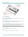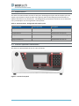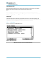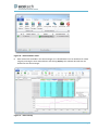
1
Serinus 10 Ozone Analyser User Manual Version: 2.2 www.ecotech.com Ser in u s 1 0 Us er M an u a l 2. 2 This page is intentionally blank Page 2 Table of Contents Table of Contents............................................................................................................................................................... 3 List of Figures ..................................................................................................................................................... 6 List of Tables....................................................................................................................................................... 8 List of Equations ................................................................................................................................................. 9 Manufacturer’s Statement .............................................................................................................................................. 10 Safety Requirements ....................................................................................................................................................... 11 Warranty.......................................................................................................................................................................... 11 Service and Repairs .......................................................................................................................................................... 12 Service Guidelines ............................................................................................................................................ 12 CE Mark Declaration of Conformity ................................................................................................................................. 13 Claims for Damaged Shipments and Shipping Discrepancies .......................................................................................... 14 Damaged Shipments ........................................................................................................................................ 14 Shipping Discrepancies ..................................................................................................................................... 14 Contact Details ................................................................................................................................................. 14 Internationally Recognised Symbols on Ecotech Equipment ........................................................................................... 15 Manual Revision History .................................................................................................................................................. 16 1. 2. Introduction .................................................................................................................................... 17 1.1 Description .......................................................................................................................................................... 17 1.2 Specifications ...................................................................................................................................................... 17 1.2.1 Measurement ...................................................................................................................................... 17 1.2.2 Precision/Accuracy .............................................................................................................................. 17 1.2.3 Calibration ........................................................................................................................................... 18 1.2.4 Power ................................................................................................................................................ 18 1.2.5 Operating Conditions ........................................................................................................................... 18 1.2.6 Communications .................................................................................................................................. 19 1.2.7 Physical Dimension .............................................................................................................................. 19 1.2.8 Certifications ........................................................................................................................................ 19 1.3 Nomenclature ..................................................................................................................................................... 20 1.4 Background/Theory ............................................................................................................................................. 20 1.4.1 Measurement Theory .......................................................................................................................... 21 1.4.2 Kalman Filter Theory ............................................................................................................................ 21 1.5 Instrument Description ....................................................................................................................................... 21 1.5.1 Calibration Manifold ............................................................................................................................ 22 1.5.2 Sample Filter ........................................................................................................................................ 22 1.5.3 Ozone Scrubber ................................................................................................................................... 22 1.5.4 Optical Bench ....................................................................................................................................... 22 1.5.5 Lamp ................................................................................................................................................ 22 1.5.6 Optical Cell ........................................................................................................................................... 23 1.5.7 Detector ............................................................................................................................................... 23 1.5.8 Main Controller PCB ............................................................................................................................ 24 1.5.9 Pressure Sensor/PCB ........................................................................................................................... 24 1.5.10 Power Supply ....................................................................................................................................... 24 1.5.11 On/Off Switch ...................................................................................................................................... 24 1.5.12 Communications .................................................................................................................................. 24 Installation ...................................................................................................................................... 27 Page 3 Ser in u s 1 0 Us er M an u a l 2. 2 3. 4. 2.1 Initial Check ........................................................................................................................................................ 27 2.2 Mounting/Installing ............................................................................................................................................ 28 2.3 Instrument Set-up ............................................................................................................................................... 29 2.3.1 Pneumatic Connections ...................................................................................................................... 29 2.3.2 Power Connections ............................................................................................................................. 30 2.3.3 Communications Connections............................................................................................................. 30 2.3.4 Analyser Set-up ................................................................................................................................... 31 2.4 U.S. EPA Equivalent Set-up ................................................................................................................................. 31 2.5 EN Type Approval Set-up .................................................................................................................................... 33 2.6 Transporting/Storage.......................................................................................................................................... 33 Operation ....................................................................................................................................... 35 3.1 Warm-up............................................................................................................................................................. 35 3.2 Measurement ..................................................................................................................................................... 36 3.3 General Operation Information .......................................................................................................................... 36 3.4 Main Display ....................................................................................................................................................... 38 3.5 Menus & Screens ............................................................................................................................................... 39 3.5.1 Quick Menu ......................................................................................................................................... 39 3.5.2 Main Menu .......................................................................................................................................... 40 3.5.3 Analyser State ..................................................................................................................................... 41 3.5.4 Status ................................................................................................................................................ 41 3.5.5 Temperatures ...................................................................................................................................... 42 3.5.6 Pressures & Flow ................................................................................................................................. 42 3.5.7 Voltages............................................................................................................................................... 43 3.5.8 General Settings .................................................................................................................................. 43 3.5.9 Measurement Settings ........................................................................................................................ 44 Average Period ................................................................................................................................................ 44 3.5.10 Calibration Menu ................................................................................................................................ 44 3.5.11 Manual Mode ...................................................................................................................................... 45 3.5.12 Timed Mode ........................................................................................................................................ 46 3.5.13 Flow Calibration .................................................................................................................................. 46 3.5.14 Service ................................................................................................................................................ 47 3.5.15 Diagnostics .......................................................................................................................................... 47 3.5.16 Digital Pots .......................................................................................................................................... 48 3.5.17 Valve Menu ......................................................................................................................................... 49 3.5.18 Tests ................................................................................................................................................ 49 3.5.19 Calculation Factors .............................................................................................................................. 50 3.5.20 Communications Menu ....................................................................................................................... 50 3.5.21 Data Logging Menu ............................................................................................................................. 50 3.5.22 Serial Communications ........................................................................................................................ 51 3.5.23 Analog Input Menu ............................................................................................................................. 52 3.5.24 Analog Output Menu........................................................................................................................... 52 3.5.25 Digital Inputs Menu ............................................................................................................................. 53 3.5.26 Digital Outputs Menu .......................................................................................................................... 53 3.5.27 Network Adaptor Menu ...................................................................................................................... 54 3.5.28 Bluetooth Menu .................................................................................................................................. 55 Communications ............................................................................................................................ 57 4.1 RS232 Communication........................................................................................................................................ 57 4.2 USB Communication ........................................................................................................................................... 57 Page 4 5. 6. 4.3 TCP/IP Network Communication (optional) ........................................................................................................ 58 4.4 Digital/Analog Communication ........................................................................................................................... 58 4.4.1 Analog Outputs .................................................................................................................................... 58 4.4.2 Analog Output Calibration Procedure.................................................................................................. 58 4.4.3 Analog Inputs ....................................................................................................................................... 59 4.4.4 Digital Status Inputs ............................................................................................................................. 59 4.4.5 Digital Status Outputs .......................................................................................................................... 59 4.5 Using Airodis Software to Download Data from a Serinus Gas Analyser ............................................................ 61 4.5.1 Installation ........................................................................................................................................... 61 4.5.2 Connecting the Serinus to your PC ...................................................................................................... 61 4.5.3 Installing Airodis .................................................................................................................................. 65 4.5.4 Configuring Airodis .............................................................................................................................. 65 4.6 Serinus Remote App/Bluetooth .......................................................................................................................... 71 4.6.1 Installation ........................................................................................................................................... 71 4.6.2 Connecting to the Analyser ................................................................................................................. 71 4.6.3 Control Serinus Analyser...................................................................................................................... 72 4.6.4 Real-time Plot ...................................................................................................................................... 74 4.6.5 Download............................................................................................................................................. 74 4.6.6 Get Parameters .................................................................................................................................... 75 4.6.7 Preferences .......................................................................................................................................... 76 Calibration ...................................................................................................................................... 79 5.1 Overview ............................................................................................................................................................. 79 5.2 Photometric Assembly Calibration Procedure .................................................................................................... 80 5.3 Calibration Procedure ......................................................................................................................................... 83 5.3.1 General Operation ............................................................................................................................... 83 5.3.2 Preparation .......................................................................................................................................... 83 5.3.3 Assay of O3 Concentrations ................................................................................................................. 84 5.3.4 Certification of Transfer Standards ...................................................................................................... 86 5.4 Zero Calibration ................................................................................................................................................... 86 5.5 Span Calibration .................................................................................................................................................. 87 5.6 Multipoint Precision Check ................................................................................................................................. 88 5.7 Precision Check ................................................................................................................................................... 90 5.8 Pressure Calibration ............................................................................................................................................ 90 5.8.1 Pressure Calibration (with internal pump option only) ....................................................................... 93 5.8.2 Flow Calibration (with internal pump option only) .............................................................................. 95 5.9 Pressurised Zero Valve ........................................................................................................................................ 98 Service .......................................................................................................................................... 101 6.1 Pneumatic Diagram ........................................................................................................................................... 101 6.2 Maintenance Tools ............................................................................................................................................ 101 6.3 Maintenance Schedule ...................................................................................................................................... 102 6.4 Maintenance Procedures .................................................................................................................................. 102 6.4.1 Particulate Filter Replacement .......................................................................................................... 102 6.4.2 Clean Fan Filter .................................................................................................................................. 103 6.4.3 Leak Check ......................................................................................................................................... 104 6.4.4 Ozone Scrubber Check ....................................................................................................................... 105 6.4.5 Clean Pneumatics .............................................................................................................................. 106 6.4.6 UV Lamp Check .................................................................................................................................. 108 Page 5 Ser in u s 1 0 Us er M an u a l 2. 2 6.4.7 6.4.8 6.4.9 7. 8. Orifice Replacement .......................................................................................................................... 108 Pressure Sensor Check ...................................................................................................................... 109 Battery Replacement......................................................................................................................... 110 6.5 Parts List ........................................................................................................................................................... 111 6.6 Bootloader ........................................................................................................................................................ 112 6.6.1 Display Help Screen ........................................................................................................................... 113 6.6.2 Communications Port Test ................................................................................................................ 113 6.6.3 Updating Firmware ........................................................................................................................... 113 6.6.4 Upgrade from USB Memory Stick ..................................................................................................... 113 6.6.5 Erase All Settings ............................................................................................................................... 113 6.6.6 Start Analyser .................................................................................................................................... 113 Troubleshooting ........................................................................................................................... 115 7.1 Flow Fault ......................................................................................................................................................... 117 7.2 Noisy/Unstable Readings .................................................................................................................................. 118 7.3 Lamp Temperature Failure ............................................................................................................................... 119 Optional Extras............................................................................................................................. 121 8.1 Dual sample filter PN E020100 ......................................................................................................................... 121 8.2 Rack Mount Kit PN E020116 ............................................................................................................................. 121 8.3 Internal Pump PN E020105 ............................................................................................................................... 125 8.3.1 Component Changes ......................................................................................................................... 125 8.3.2 Removed Components ...................................................................................................................... 126 8.3.3 Flow Calibration ................................................................................................................................ 126 8.3.4 Pressure Calibration Procedure......................................................................................................... 126 8.4 Pressurised Zero Valve PN E020109 ................................................................................................................. 126 Appendix A. Advanced Protocol Parameter List ....................................................................... 127 Appendix B. EC9800 Protocol ................................................................................................... 137 Appendix C. Bavarian Protocol ................................................................................................. 139 Appendix D. ModBus Protocol .................................................................................................. 145 Appendix E. Beer-Lambert Law................................................................................................. 147 List of Figures Figure 1 – Major components ............................................................................................................... 22 Figure 2 – Lamp type switch setting ...................................................................................................... 23 Figure 3 – Opening the instrument ....................................................................................................... 27 Figure 4 – Instrument back panel .......................................................................................................... 29 Figure 5 – Switching the battery on/off ................................................................................................ 34 Figure 6 – Serinus front panel ............................................................................................................... 36 Figure 7 – Main screen .......................................................................................................................... 38 Figure 8 – Main menu screen ................................................................................................................ 40 Page 6 Figure 9 – Communication ports ............................................................................................................ 57 Figure 10 – Serinus 25-pin microprocessor board (with default jumpers highlighted) ......................... 60 Figure 11 – External 25pin I/O individual pin descriptions .................................................................... 60 Figure 12 – Configure Serinus logging interval....................................................................................... 61 Figure 13 – Installing driver software..................................................................................................... 61 Figure 14 – Installing driver software..................................................................................................... 62 Figure 15 – Installing driver software..................................................................................................... 62 Figure 16 – Installing driver .................................................................................................................... 63 Figure 17 – Successful driver installation ............................................................................................... 63 Figure 18 – Serial communications menu .............................................................................................. 64 Figure 19 – Network adaptor menu ....................................................................................................... 64 Figure 20 – Airodis workspace manager ................................................................................................ 65 Figure 21 – Adding a new station ........................................................................................................... 66 Figure 22 – New station connection ...................................................................................................... 66 Figure 23 – Station configuration ........................................................................................................... 67 Figure 24 – Error status notification ...................................................................................................... 68 Figure 25 – Downloading data ............................................................................................................... 68 Figure 26 – Download data status.......................................................................................................... 69 Figure 27 – Data visibility ....................................................................................................................... 69 Figure 28 – Exporting data ..................................................................................................................... 70 Figure 29 – Data download complete .................................................................................................... 70 Figure 30 – Downloading the app from Google Play store .................................................................... 71 Figure 31 – Bluetooth pairing request ................................................................................................... 72 Figure 32 – Entering numbers into the Serinus Application .................................................................. 73 Figure 33 – Switching analysers in the Serinus Application ................................................................... 73 Figure 34 – Real-time plot ...................................................................................................................... 74 Figure 35 – Plot of downloaded data ..................................................................................................... 75 Figure 36 – Directory settings ................................................................................................................ 76 Figure 37 – Logs format.......................................................................................................................... 76 Figure 38 – Colour theme settings ......................................................................................................... 77 Figure 39 – Typical UV Photometric Calibration System........................................................................ 81 Figure 40 – Excel graph of multipoint calibration .................................................................................. 89 Figure 41 – Pressure calibration ............................................................................................................. 90 Figure 42 – Pressure calibration; external pressure meter .................................................................... 91 Figure 43 – Vacuum set point screen ..................................................................................................... 91 Figure 44 – Editing vacuum set point ..................................................................................................... 91 Figure 45 – Ambient set point calibration screen .................................................................................. 92 Figure 46 – Setting the ambient set point.............................................................................................. 92 Figure 47 – Exiting the calibration menu ............................................................................................... 93 Figure 48 – Pressure calibration menu .................................................................................................. 93 Figure 49 – Calibration menu ................................................................................................................. 93 Figure 50 – Pressure calibration menu .................................................................................................. 94 Figure 51 – Vacuum Set Pt ..................................................................................................................... 94 Figure 52 – Pump bypass flow................................................................................................................ 94 Page 7 Ser in u s 1 0 Us er M an u a l 2. 2 Figure 53 – Ambient Set Pt .................................................................................................................... 95 Figure 54 – Pump bypass flow ............................................................................................................... 95 Figure 55 – Exit pressure calibration menu ........................................................................................... 95 Figure 56 – Flow calibration menu ........................................................................................................ 96 Figure 57 – Zero flow ............................................................................................................................. 96 Figure 58 – Course control .................................................................................................................... 96 Figure 59 – Cal point .............................................................................................................................. 97 Figure 60 – Manual flow control ........................................................................................................... 97 Figure 61 – Flow set point ..................................................................................................................... 97 Figure 62 – Single high pressure zero calibration option ...................................................................... 99 Figure 63 – Serinus 10 pneumatic diagram ......................................................................................... 101 Figure 64 – Removing plunger ............................................................................................................. 103 Figure 65 – Removing fan filter ........................................................................................................... 103 Figure 66 – Pressure gauge on exhaust ............................................................................................... 104 Figure 67 –Loosening nut from detector............................................................................................. 106 Figure 68 – Removing tube.................................................................................................................. 106 Figure 69 – Removing screws .............................................................................................................. 107 Figure 70 – Removing glass tube ......................................................................................................... 107 Figure 71 – Location of UV lamp fastening grub screw ....................................................................... 108 Figure 72 – Kynar fitting containing orifice ......................................................................................... 109 Figure 73 – Test point location ............................................................................................................ 110 Figure 74 – Typical test point reading of cell pressure sensor ............................................................ 110 Figure 75 – Flow fault diagnostic procedure ....................................................................................... 117 Figure 76 – Noisy zero or unstable span diagnostic procedure .......................................................... 118 Figure 77 – Lamp temperature failure diagnostic procedure ............................................................. 119 Figure 78 – Dual filter option installed ................................................................................................ 121 Figure 79 – Separate rack slides .......................................................................................................... 122 Figure 80 – Assemble inner slide on chassis........................................................................................ 122 Figure 81 – Attach rack mount adaptors to outer slides ..................................................................... 123 Figure 82 – Attach slides to front of rack ............................................................................................ 123 Figure 83 – Attach rack mount adaptors to outer slides ..................................................................... 123 Figure 84 – Attach rear rack mount adaptors to slide......................................................................... 124 Figure 85 – Rack mount ears fitted to analyser................................................................................... 124 Figure 86 – Slide clips .......................................................................................................................... 125 List of Tables Table 1 – Manual revision history ......................................................................................................... 16 Table 2 – Measurements: background and sample cycles ................................................................... 36 Table 3 – Digital pots ............................................................................................................................. 48 Table 4 – Analog outputs ....................................................................................................................... 58 Table 5 – Setting up a new station via Airodis ...................................................................................... 66 Page 8 Table 6 – Maintenance schedule ......................................................................................................... 102 Table 7 – Spare parts List ..................................................................................................................... 111 Table 8 – Serinus 10 Maintenance Kit .................................................................................................. 111 Table 9 – Other Consumables – Not listed in Maintenance Kit ........................................................... 112 Table 10 – Troubleshooting list ............................................................................................................ 115 Table 11 – Internal pump components ................................................................................................ 125 Table 12 – Internal pump removed components ................................................................................ 126 Table 13 – Advanced protocol parameter list ...................................................................................... 127 Table 14 – Bavarian data ...................................................................................................................... 139 Table 15 – Block check operation ........................................................................................................ 140 Table 16 – Bavarian Protocol Commands ............................................................................................ 140 Table 17 – Bit map................................................................................................................................ 142 Table 18 – Bit map (positive logic) ....................................................................................................... 142 List of Equations Equation 1 – Beer-Lambert Absorption Law ......................................................................................................... 80 Equation 2 – Modified Beer-Lambert Absorption Law .......................................................................................... 80 Equation 3 – Modified Beer-Lambert Absorption Law .......................................................................................... 81 Equation 4 – Linearity error equation ................................................................................................................... 83 Equation 5 – Beer-Lambert equation .................................................................................................................... 84 Equation 6 – Instrument accuracy ......................................................................................................................... 89 Equation 7 – Beer-Lambert Law .......................................................................................................................... 147 Page 9 Ser in u s 1 0 Us er M an u a l 2. 2 Manufacturer’s Statement Thank you for selecting the Ecotech Serinus 10 Ozone Analyser. The Serinus series is the next generation of Ecotech designed and manufactured gas analysers. The Serinus 10 will perform ozone measurements over a range of 0-20ppm with a lower detectable limit of 0.5 ppb. This User Manual provides a complete product description including operating instructions, calibration, and maintenance requirements for the Serinus 10. Reference should also be made to the relevant local standards which should be used in conjunction with this manual. Some relevant standards are listed in the references section of this manual. If, after reading this manual you have any questions or you are still unsure or unclear on any part of the Serinus 10 then please do not hesitate to contact Ecotech or your local Ecotech distributor. Please help the environment and recycle the pages of this manual when you have finished using it. Notice The information contained in this manual is subject to change without notice. Ecotech reserves the right to make changes to equipment construction, design, specifications and/or procedures without notice. Copyright © 2013. All rights reserved. Reproduction of this manual, in any form, is prohibited without the written consent of Ecotech Pty Ltd. CAUTION Hazardous voltages exist within the analyser. The analyser lid should be closed when the analyser is left unattended or turned on. Ensure the power cable, plugs and sockets are maintained in a safe working condition. Page 10 Safety Requirements To reduce the risk of personal injury caused by electrical shock, follow all safety notices and warnings in this documentation. If the equipment is used for purposes not specified by Ecotech, the protection provided by this equipment may be impaired. Replacement of any part should only be carried out by qualified personnel, using only parts specified by Ecotech as these parts meet stringent Ecotech quality assurance standards. Always disconnect the power source before removing or replacing any components. Warranty This product has been manufactured in an ISO 9001/ISO 14001 facility with care and attention to quality. The product is subject to a 24-month warranty on parts and labour from date of shipment. The warranty period commences when the product is shipped from the factory. Lamps, fuses, filters batteries and other consumable items are not covered by this warranty. Each analyser is subjected to a vigorous testing procedure prior to despatch and will be accompanied with a parameter list and a multipoint calibration check thereby enabling the analyser to be installed and ready for use without any further testing. Page 11 Ser in u s 1 0 Us er M an u a l 2. 2 Service and Repairs Our qualified and experienced technicians are available to provide fast and friendly service between the hours of 8:30am – 5:00pm AEST Monday to Friday. Please contact either your local distributor or Ecotech regarding any questions you have about your analyser. Service Guidelines In the first instance, please call or email us if you are experiencing any problems or issues with your analyser. If you are within Australia or New Zealand please contact our service response centre via email on [email protected] or call +61 (0)3 9730 7800 If outside of Australia and New Zealand please email our international support department at [email protected] or call +61 3 9730 7800 If we cannot resolve the problem through technical support, please email the following information: Name and phone number Company name Shipping address Quantity of items being returned Model number/s or a description of each item Serial number/s of each item (if applicable) A description of the problem Original sales order or invoice number related to the equipment When you email us we will assign a Return Material Authorisation (RMA) number to your shipment and initiate the necessary paperwork to process your equipment within 48 hours. Please include this RMA number when you return equipment, preferably both inside and outside the shipping packaging. This will ensure you receive prompt service. Page 12 CE Mark Declaration of Conformity This declaration applies to the Serinus 10 Ozone Analyser as manufactured by Ecotech Pty. Ltd. of 1492 Ferntree Gully Rd, Knoxfield, VIC, 3180, Australia. The instrument to which this declaration relates is in conformity with the following European Union Directives: Council Directive of 15 December 2004 on the approximation of the laws of Member States relating to electromagnetic compatibility (2004/108/EC) The following standard was applied: EN 61326-1:2006 Electrical equipment for measurement, control and laboratory use – EMC Requirements – Part 1: General requirements. Immunity Requirements EN 61326-1 IEC-61000-4-2 Electrostatic discharge immunity IEC-61000-4-3 Radiated RF immunity IEC-61000-4-4 Electrical fast transient burst immunity IEC-61000-4-5 Surge immunity IEC-61000-4-6 Conducted RF immunity IEC-61000-4-11 Voltage dips and interruption immunity Electromagnetic Compatibility EN 61326-1 CISPR-11 Radiated RF emission measurements CISPR-11 Mains terminal RF emission measurements IEC-61000-3-3 Mains terminal voltage fluctuation measurements IEC-61000-3-2 Power frequency harmonic measurements Council Directive of 12 December 2006 on the harmonisation of the laws of Member States relating to electrical equipment designed for use within certain voltage limits (2006/95/EC) The following standard was applied: EN 61010-1:2001 Safety requirements for electrical equipment, for measurement control and laboratory use – Part 1: General requirements. For protection against: Electric shock or burn Mechanical HAZARDS Excessive temperature Spread of fire from the equipment Effects of radiation, including laser sources and sonic and ultrasonic pressure Page 13 Ser in u s 1 0 Us er M an u a l 2. 2 Claims for Damaged Shipments and Shipping Discrepancies Damaged Shipments Inspect all instruments thoroughly on receipt. Check materials in the container/s against the enclosed packing list. If the contents are damaged and/or the instrument fails to operate properly, notify the carrier and Ecotech immediately. The following documents are necessary to support claims: Original freight bill and bill of lading Original invoice or photocopy of original invoice Copy of packing list Photographs of damaged equipment and container You may want to keep a copy of these documents for your records. Please refer to the instrument name, model number, serial number, sales order number, and your purchase order number on all claims. You should also: Contact you freight forwarder for an insurance claim Retain packing material for insurance inspection Shipping Discrepancies Check all packages against the packing list immediately on receipt. If a shortage or other discrepancy is found, notify the carrier and Ecotech immediately. We will not be responsible for shortages against the packing list unless they are reported promptly (within 7 days). Contact Details Head Office 1492 Ferntree Gully Road, Knoxfield VIC Australia 3180 Phone: +61 (0)3 9730 7800 Fax: +61 (0)3 9730 7899 Email: [email protected] Service: [email protected] International Support: [email protected] www.ecotech.com Page 14 Internationally Recognised Symbols on Ecotech Equipment Electrical fuse IEC 60417-5016 Earth (ground) terminal IEC 60417-5017 Protective conductor terminal IEC 60417-5017 Equipotentiality IEC 60417-5021 Alternating current IEC 60417-5032 Caution, hot surface IEC 60417-5041 Caution, risk of danger. Refer to accompanying documents ISO 7000-0434 Caution, risk of electric shock ISO 3864-5036 Page 15 Ser in u s 1 0 Us er M an u a l 2. 2 Manual Revision History Manual PN: M010026 Current revision: 2.2 Date released: 10 December 2013 Description: User Manual for the Serinus 10 Ozone Analyser This manual is the full user manual for the Serinus 10 Ozone Analyser. This manual contains all relevant information on theory, specifications, installation, operation, maintenance and calibration. Any information that cannot be found within this manual can be obtained by contacting Ecotech. Table 1 – Manual revision history Edition Date Summary Pages 1.0 September 2008 Initial Release All 1.1 December 2008 Menu updates and general corrections All 1.2 March 2009 New maintenance procedures 36, 46 Updated analyser setup 12-13 Small corrections Various New menu items added 19-30 Serinus downloader added 125 Internal pump option added 135 USB - Advanced Parameters updated Various 1.3 November 2009 Minor corrections 1.4 September 2010 CE conformity added iv Parts list updated 111 Pressurised zero valve added 126 Updates to rack mount option 121 Updates to Serinus downloader Update to 25 pin I/O Update to network communications 2.0 July 2012 New chassis Various Update menu system Add Bluetooth menu Serinus Remote Android App Rack mount procedure update Analog output calibration 2.1 March 2013 Formatting updates All 2.2 November 2013 Formatting updates All Page 16 1. Introduction 1.1 Description The Serinus 10 Ozone Analyser uses non-dispersive ultraviolet (UV) absorption technology to measure ozone to a sensitivity of 0.5ppb in the range of 0-20ppm. The Serinus 10 measures O3 with the following components and techniques: Mercury vapour lamp – to generate UV light at a wavelength that ozone will absorb (254nm). Photodiode detector – to capture the measurement response. Detects the remaining UV light after absorption, leading to the concentration of ozone. Ozone scrubber – to establish the background response. As ozone is not the only atmospheric gas that absorbs this particular wavelength of UV light. A microprocessor programmed with Serinus firmware monitors the detector response and many other parameters. The O3 concentrations are automatically corrected for gas temperature and pressure changes and when using gravimetric units (e.g. µg/m³) is referenced to 0°C, 20°C or 25°C at 1 atmosphere. This allows the Serinus 10 to provide readings in the relevant units for your requirements. The U.S. EPA has designated the Serinus 10 Ozone Analyser as an equivalent method and SIRA has designated it as an EN approved instrument. 1.2 Specifications 1.2.1 Measurement Range 0-20 ppm auto ranging USEPA designated range: 0-0.5 ppm MCERTS EN certification range: 0 to 250 ppb Lower detectable limit: 0.5 ppb, with Kalman filter active 1.2.2 Precision/Accuracy Precision 0.5 ppb or 0.2% of reading, whichever is greater Linearity <1% of full scale Page 17 Ser in u s 1 0 Us er M an u a l 2. 2 Noise at Zero <0.25 ppb Response Time 30 seconds to 95% Sample Flow Rate 0.5 slpm 1.2.3 Calibration Zero Drift Temperature dependant: 1.0 ppb per °C 24 hours: < 0.3 ppb 7 days: < 0.3 ppb Span Drift Temperature dependant: 0.1% per °C 7 days: 0.5% of reading 1.2.4 Power Operating Voltage 99 to 132 VAC (57-63 Hz) or via switch 198 to 264 VAC (47 to 53 Hz) U.S. EPA designated range: 105 to 125 VAC, 60 Hz Power Consumption 85 VA maximum (typical at start-up) 65 VA after warm-up Fuse Rating 20x5 mm, T 250 V, 5 A (slow blow) 1.2.5 Operating Conditions Ambient Temperature Range 0 °C to 40 °C (32 °F to 104 °F) U.S. EPA designated range: 20 °C to 30 °C Page 18 Sample Pressure Dependence 5% change in pressure produces less than a 1% change in reading Maximum altitude: 3000 m above sea level 1.2.6 Communications USB port connection on rear panel Bluetooth (digital communication via Android App) TCP/IP Ethernet network connection (optional) RS232 port #1: Normal digital communication. RS232 port #2: Multi-drop port used for multiple analyser connections on a single RS232 cable. USB memory stick (front panel) for data logging, event logging and parameter/configuration storage. Protocols Modbus RTU/TCP, Bavarian, EC9800, Advanced. 25 pin I/O Port Analog output (menu selectable current or voltage output) o Current output of 0-20 mA, 2-20 mA or 4-20 mA o Voltage output of 0 to 5 V, with menu selectable zero offset of 0V, 0.25V or 0.5V o Range: 0 to full scale from 0-0.05 ppm to 0-20 ppm 8 digital outputs, open collector max 400mA/12VDC (Max total output 2A) 8 digital inputs, 0-5VDC, CAT I rated Three analog voltage inputs, 0-5VDC, CAT I rated 1.2.7 Physical Dimension Case Dimensions Rack length (front to rear): Total length (w/ latch release): 597 mm (23.5”) 638 mm (25.1”) Chassis width: Front panel width: 418 mm (16.5”) 429 mm (16.9”) Chassis height: Front panel height: 163 mm/uses 4RU (6.4”) 175 mm (6.9”) Weight: 17.2 kg 1.2.8 Certifications U.S. EPA approved (EQOA-0809-187) Page 19 Ser in u s 1 0 Us er M an u a l 2. 2 EN approval (Sira MC 100165/02) Ultraviolet photometry method EN14625 Determination of Ozone AS3580.6.1 Australian/New Zealand Standards 1.3 Nomenclature O3 Ozone Span: A gas sample of known composition and concentration used to calibrate/check the upper range of the instrument (ozone). Zero: Zero calibration uses zero air (ozone scrubbed ambient air) to calibrate/check the lower range of the instrument. Background: Is the reading of the sample without ozone present in the measurement cell. Zero Drift: The change in instrument response to zero air over a period of continuous unadjusted operation. Zero Air: Is purified air in which the concentration of O3 is <0.5 ppb with water vapour of less than 10% RH. Sufficient purified air can be obtained by passing dry ambient air through an activated charcoal filter and a particulate filter. External Span Source: Span gas that is delivered via an external ozone generator. Sample Air: Sample air is defined as the sample before it has entered the measurement cell, as distinguished from the exhaust air. Exhaust Air: Exhaust air is the sample air after it has passed through the measurement cell and is moving towards being expelled from the analyser. ID and OD: These are measurements of tubing. ID is the internal diameter of tubing, OD is the outer diameter. Multi-drop: A configuration of multiple analysers connected via the same RS232 cable. Photomultiplier Tube: A highly sensitive device which can detect extremely low levels of light (photons) and multiply the electrical signal to a point where it can be accurately measured. These are often called PMTs for short. Bootloader: A program that checks whether the current firmware is valid, then executes the instrument start-up. The bootloader can be entered by pressing the ‘+’ key on the front keypad during the first ½ second after power on, and following the prompts. The bootloader then enables various low level recovery tools, including updating the main firmware from a USB key. 1.4 Background/Theory Within the industrial sector, ozone is not directly emitted to the atmosphere. Its formation is normally due to the reaction of sunlight on air containing hydrocarbons and nitrogen oxides. Ozone in the ambient air is also found to create other pollutants in the air, such as components of smog. Page 20 Ground-level ozone has become a global air pollution problem. According to measurements at remote sites, the ozone background concentration in the northern hemisphere has increased by about 2 ppb (approximately 6 %) per decade since 1980 and is expected to rise further. Ozone has been found to affect human health (when close to ground level) by harming the respiratory and immune system. People with pre-existing respiratory damage or diseases are more likely to suffer from the effects of ozone. 1.4.1 Measurement Theory Ozone is measured by UV absorption analysis. The UV photometer determines the concentration of ozone (O3) in a sample gas at ambient pressure by detecting the absorption of UV radiation in a glass absorption tube. The Serinus 10 follows these principles and measurement techniques: Ozone shows strong absorption of UV light at 254nm. Sample air is passed into the glass absorption tube (measurement cell). Within the measurement cell a single beam of UV radiation (from a mercury vapour lamp) passes through the sample and is absorbed by the ozone. The solar blind vacuum photodiode detects any UV that is not absorbed. The strength of the UV signal being detected is proportional to the amount of UV light being absorbed by ozone. The Serinus 10 analyser uses the Beer-Lambert relationship (Beer-Lambert Law) to calculate the ozone concentration. O3 is not the only gas that absorbs UV (254nm), SO2 and aromatic compounds also absorb radiation at this wavelength. To eliminate these interferences a second cycle is performed. Sample air is passed through an ozone scrubber, removing ozone but allowing all interfering gases through. Therefore, accurately measuring the effect of interfering gases. This effect is then removed from the sample measurement signal. This enables the accurate measurement of ozone without the influence of interferrants. The microprocessor and electronics of the Serinus 10 control, measure, and correct for all the major external variables to ensure stable and reliable operation. 1.4.2 Kalman Filter Theory The digital Kalman filter provides an ideal compromise between response time and noise reduction for the type of signal and noise present in ambient air analysers. The Kalman filter enhances measurements by modifying the filter time base variable, depending on the change rate of the measured value. If the signal is changing rapidly, the instrument is allowed to respond quickly. When the signal is steady, a long integration time is used to reduce noise. The system continuously analyses the signal and uses the appropriate filtering time. 1.5 Instrument Description The major components of the Serinus 10 are described below: Page 21 Ser in u s 1 0 Us er M an u a l 2. 2 Figure 1 – Major components 1.5.1 Calibration Manifold The instrument features a three way calibration valve manifold to enable selection of either, external calibration gas, ambient air, or O3 free gas. 1.5.2 Sample Filter The particulate filter is a Teflon 5 micron (µm) filter with a diameter of 47mm. This filter eliminates all particles larger than 5µm that could interfere with sample measurement. 1.5.3 Ozone Scrubber The ozone scrubber uses manganese dioxide (MnO2) to selectively destroy ozone by catalytic means from the sample air while all other interferants remain. This scrubber is used to remove the effect interferants have on the final O3 measurement by correcting for their UV absorption. Note: High concentrations of aromatic hydrocarbons may interfere with ozone measurements. 1.5.4 Optical Bench The optical bench consists of the lamp, detector, and optical cell. 1.5.5 Lamp The UV source is a mercury vapour lamp that emits radiation around 254nm. Page 22 Lamp Driver PCB This driver generates a high voltage and high frequency switching supply to start and maintain the UV lamp at a pulsed constant intensity. The lamp current is set by the microprocessor and is maintained at 10 mA. The lamp driver PCB is located under the UV absorption cell. CAUTION The lamp driver PCB contains high voltages. Ensure instrument is turned off before accessing this component. Lamp Power Supply The high frequency lamp driver is set for 10mA power output at 800-1100 V. Note: Switch S1 indicates the lamp type. The correct setting must be used or damage to the electronics will occur. For the Serinus 10 (which measures O3), switches 1 & 2 must be in the “Off” position, and switches 3 & 4 must be in the “On” position (refer to Figure 2 – Lamp type switch setting Figure 2 – Lamp type switch setting 1.5.6 Optical Cell The optical cell is a glass tube with a UV source at one end and a detector at the other. UV radiation is sequentially absorbed by sample gas and ozone free sample gas over the length of the reaction cell. The remaining light reaching the detector is measured and used to calculate the O3 concentration. 1.5.7 Detector The detector is a solar blind vacuum diode sensitive only in the spectral region where O3 absorbs (254nm). This sensor is used to monitor the intensity of the residual light after absorption in the reaction cell. The UV detector preamplifier converts the detector’s current output into a voltage level for the main PCB A/D converter. Page 23 Ser in u s 1 0 Us er M an u a l 2. 2 1.5.8 Main Controller PCB The main controller PCB controls all the processes within the instrument. It contains a battery backed clock, calendar and an on-board microprocessor. The main controller PCB is located on top of the other components with the analyser. The PCB pivots on hinges to allow access to the components underneath. CAUTION Never place objects on top of the main controller PCB as it may result in damage. 1.5.9 Pressure Sensor/PCB An absolute-pressure transducer is mounted on the measurement cell, and used to measure the sample pressure in the cell. This pressure is used to check for flow and correct readings for pressure variations. 1.5.10 Power Supply The power supply is a self-contained unit housed in a steel case. It has a selectable input voltage of 115 or 230 VAC 50/60 Hz and an output voltage of 12 VDC power for distribution within the analyser. CAUTION Input voltage can be manually changed by sliding the red switch left (230) for 220240V or right (110) for the 100-120V. Ensure the switch is set to the correct voltage (from supply) before switching on. 1.5.11 On/Off Switch Located on the back panel (bottom right facing the rear of the instrument). 1.5.12 Communications Communication between the analyser and either a data logger, laptop or network can be performed with the following communication connections located on the back panel. RS232 #1 This port is designed to be used for simple RS232 communication. RS232 #2 This port is designed to be used for simple RS232 communication, or in multi-drop configuration. USB This port can be used for instrument communication and is also good for quickly downloading data, onsite diagnostics, maintenance and firmware upgrades. Page 24 TCP/IP (optional) This port is best used for remote access and real-time access to instruments when a network is available to connect with. External I/O Port The analog/digital port sends and receives analog/digital signals to other devices. These signals are commonly used to activate gas calibrators or for warning alarms. Analog Outputs The analyser is equipped with three analog outputs. Menu selectable as either voltage output 0-5VDC, or current output 0-20, 2-20, 4-20 mA. Analog Inputs The analyser is also equipped with three analog voltage inputs (0-5VDC CAT 1) with resolution of 15 bits plus polarity. CAUTION Exceeding these voltages can permanently damage the instrument and void the warranty. Digital Status Inputs The analyser is equipped with 8 logic level inputs (0–5VDC CAT 1) for the external control of zero/span calibration sequences. CAUTION Exceeding these voltages can permanently damage the instrument and void the warranty. Digital Status Outputs The analyser is equipped with 8 open collector outputs which will convey instrument status conditions and warning alarms such as no flow, sample mode, etc. CAUTION Exceeding 12VDC or drawing greater than 400mA on a single output or a total greater than 2A across the 8 outputs can permanently damage the instrument and void the warranty. Bluetooth This allows for remote access of the analyser to any Android device with the Serinus Remote Application installed on it. Uses Bluetooth to control the analyser, view parameters, download data and construct real-time graphs. Page 25 Ser in u s 1 0 Us er M an u a l 2. 2 This page is intentionally blank. Page 26 This page is intentionally blank. Page 27 Ser in u s 1 0 Us er M an u a l 2. 2 2. Installation 2.1 Initial Check Packaging The Serinus 10 is transported in packaging which is specifically designed to minimise the effects of shock and vibration during transportation. Ecotech recommends that the packaging be kept if there is a likelihood that the instrument is going to be relocated. Note: The red plastic caps that seal the pneumatic connections during transport must be removed prior to operation. All Serinus packaging is recyclable. Please he caps that is recyclable. Opening the Instrument Check the interior of the instrument with the following steps: 1. Undo the screws located on the rear panel. 2. Open the chassis lid by releasing the latch (pressing the button) located on the front panel in the top left-hand corner, then slide the lid backwards. 3. To completely remove the lid, slide the lid backwards until the rollers line up with the gaps in the track and pull the lid upwards to remove from the instrument (refer to Figure 3 – Opening the instrument). 4. Check that all pneumatic and electrical connectors are connected. 5. Check for any visible and obvious damage. If damage exists contact your supplier and follow the instructions in Claims for Damaged Shipments and Shipping Discrepancies at the front of this manual. Figure 3 – Opening the instrument Page 28 Items Received With the delivery of the Serinus 10, you should have received the following: Ecotech Serinus 10 instrument PN: E020010 Software CD PN: S040001 Manual PN: M010026 (hardcopy optional) USB stick PN: H030021 Power cord (120V)* PN: C040007 Power cord (240V)* Australia PN: C040009 Europe PN: C040008 UK PN: C040010 *The power cord received depends on the power supply of the country (120V or 240V). Note: Please check that all these items have been delivered undamaged. If any item appears damaged, please contact your supplier before turning the instrument on. 2.2 Mounting/Installing When installing the instrument the following points must be taken into account: The analyser should be placed in an environment with minimal dust, moisture and variation in temperature (20-30°C for U.S. EPA designated range). For best results the analyser should be located in a temperature and humidity controlled environment (air conditioned shelter). An enclosure temperature of 25-27°C is optimum. Whether in a rack or placed on a bench, the instrument should not have anything placed on top of it or touching the case. Instruments should be sited with easy access to the front panel (instrument screen/USB flash) and to the back panel (communication ports/pneumatic connections). It is recommended that the sample line be as short as possible and/or a heated manifold be used for sampling (minimising moisture condensation in the sample). Do not pressurise the sample line under any circumstances. Sample should be drawn through the instrument under atmospheric pressure. This should be done either by the internal pump option (if installed) or by an external vacuum pump connected to the exhaust port of the analyser. When supplying span gas, ensure the flow is approximately 1 lpm and excess is sufficiently vented. Note: The power on/off switch is accessible from the rear of the instrument only. Site the analyser so that the on/off power switch is accessible. Page 29 Ser in u s 1 0 Us er M an u a l 2. 2 2.3 Instrument Set-up After installing the instrument the following procedures should be followed to ready the analyser for monitoring. Figure 4 – Instrument back panel 2.3.1 Pneumatic Connections The Serinus 10 has three pneumatic ports on the back panel of the analyser; the sample port, the calibration port and the exhaust port. All tubing and fittings used should follow the instructions below: 1. Must be made of Teflon® FEP material, Kynar®, stainless steel, glass or any other suitably inert material. 2. Sample line should be no more than 2 meters in length with ⅛ inch ID, ¼ inch OD. 3. Sample inlet pressure should not exceed 5 kPa above ambient pressure. 4. Tubing must be cut squarely and any burrs removed. 5. Remove the inlet port nut, then insert the tubing through the back of the nut with the tube extending 1 inch through the front. 6. Place the tubing into the port until it hits the tube stop located inside the fitting. 7. Place the nut back onto the fitting and tighten clockwise until finger tight. 8. Nuts should be re-tightened when instrument reaches operating temperature. Sample Port The sample port must be connected to an ambient source of sample air. When using a sample manifold the Serinus requires at least 1.0 slpm delivered to the sample manifold (0.5 slpm for measurement plus approximately 0.5 SLPM overflow). Page 30 Calibration Port The calibration port should be connected to the span/zero source. It is recommended that a gas calibrator (Ecotech’s GC1100TS) or Photometer (Ecotech’s EC9811) be used which can deliver precise concentrations of ozone. Note: All connections to this port should not exceed ambient pressure. A vent is required for excess span gas. Exhaust Port The exhaust port is where the measured sample is exhausted from the analyser. The exhaust tubing should be fitted to a vacuum pump (minimum: 1 SLPM at 50 kPa) if the internal pump option is not installed in your analyser. CAUTION It is recommended that exhaust air is not expelled into a shelter/room inhabited by people. It should be expelled into the external air and away from the sample inlet. 2.3.2 Power Connections When connecting the power source the following must be adhered to: CAUTION The following points MUST be followed. Incorrect setup and activation of instrument may cause damage and will void warranty. 1. Verify that the red switch (above power switch) is switched to the correct setting (230V or 110V). 2. A three pin power plug (with ground) must be used with an earthed power socket (3 pin). 3. Connect the power plug into the mains power point and turn the power switch on. 2.3.3 Communications Connections There are a number of ways to communicate with the analyser: RS232 #1 Connect this port to a data logger (such as WinAQMS) with an RS232 cable. RS232 #2 Connect the RS232 cable from the instrument to a computer, data logger or in a multi-drop formation. Note: When using multi-drop ensure each analyser is given a unique instrument ID. Page 31 Ser in u s 1 0 Us er M an u a l 2. 2 USB Connect USB cable to computer and run either the Serinus downloader program or WinAQMS logger. TCP/IP (optional) Plug in a network cable (this cable should be attached to a network) and use the Serinus downloader program to access the instrument and download data. The Serinus downloader is supplied on the utilities CD provided with the instrument. Analog/Digital This port is used to send and receive analog and digital signals. It is normally used to connect with a gas calibrator or to activate alarm signals. Each instrument contains 8 digital inputs, 8 digital outputs, 3 analog inputs and 3 analog outputs. Bluetooth Connection is enabled using Ecotech’s Serinus Remote Android application. Use the Serinus Remote Android Application to access instrument and download data. It is available for download directly from the Google Play Store. Search for “Ecotech Serinus Remote”. 2.3.4 Analyser Set-up 1. Ensure that the USB memory key is installed. 2. Check that the battery is turned on at the main controller PCB (refer to Figure 5). 3. Turn on the instrument and allow it to warm-up (refer to Section 3.1). 4. Check/set time and date (refer to Section 3.5.8). 5. Set the digital filter to the desired monitoring option (refer to Section 3.5.9). 6. Set the internal data logging options (refer to Section 3.5.21). 7. Set the analog/digital inputs and outputs settings (refer to Section3.5.20). Perform a pressure sensor check (refer to Section 6.4.8). 8. Perform a leak check (refer to Section 6.4.3). 9. Leave the instrument to warm-up and stabilise for 2-3 hours. 10. Perform a calibration (refer to Section 5). 11. The instrument is now ready for operation. 2.4 U.S. EPA Equivalent Set-up The Serinus 10 is designated as equivalent method EQOA-0809-187 by the U.S. EPA (40 CFR Part 53). The Serinus 10 must be used under the following conditions to satisfy its equivalency: Page 32 Range 0-500ppb Ambient Temperature 20-30°C Line Voltage 105 to 125 VAC, 60 Hz Pump Ecotech optional internal or external pump Filter 5 micron PTFE filter must be installed in front of the sample inlet (zero and span gas must pass through this filter). If the units in the measurement menu are changed from volumetric to gravimetric (or gravimetric to volumetric), the analyser must be re-calibrated. The analyser must be operated and maintained in accordance with this user manual. The following menu selections must be used: Measurement Settings Background interval: Enabled Calibration Menu Span comp: Disabled Diagnostics Menu Pres/Temp/Flow comp: On Diagnostic mode: Operate Control loop: Enabled The Serinus 10 Analyser is designated U.S. EPA equivalent method with or without the following options/items: Internal pump Rack mount assembly Internal zero/span assembly (IZS) Optional ethernet port Page 33 Ser in u s 1 0 Us er M an u a l 2. 2 2.5 EN Type Approval Set-up The Serinus 10 has been certified to MCERTS Performance Standards for Continuous Ambient Air Quality Monitoring Systems. The certificate number is Sira MC100165/00. The Serinus 10 must be used under the following conditions to meet EN requirements: Range 0-250 ppb Ambient Temperature 0-30°C The analyser must be operated and maintained in accordance with this user manual. The following menu selections must be used: Calibration Menu Span comp: Disabled ServiceDiagnostics Menu Pres/Temp/Flow comp: On Diagnostic mode: Operate Control loop: Enabled 2.6 Transporting/Storage Transporting the Serinus should be done with great care. It is recommended that the packaging the Serinus was delivered in should be used when transporting or storing the instrument. When transporting or storing the instrument the following points should be followed: 1. Turn off the instrument and allow it to cool down. 2. Remove all pneumatic, power and communication connections. 3. If storing over a long period (6 months) turn the battery off by switching the switch on the main processor board (shown in Figure 5) to the left. 4. Remove the instrument from the rack. 5. Replace the red plugs into the pneumatic connections. 6. Place the instrument back into a plastic bag with desiccant packs and then seal the bag (ideally the bag it was delivered in). 7. Place the instrument back into the original foam and box it was delivered in. If this is no longer available find some equivalent packaging which provides protection from damage. 8. The instrument is now ready for long term storage or transportation. Page 34 Note: After transport or storage the instrument must be set up and calibrated (refer Section 2.3.4). Figure 5 – Switching the battery on/off Page 35 Ser in u s 1 0 Us er M an u a l 2. 2 3. Operation 3.1 Warm-up Once the instrument is turned on it will adjust itself to prepare for monitoring. No measurements are taken during the warm-up period. The following activities occur during warm-up: Lamp Adjust The microprocessor automatically adjusts the lamp’s current (10mA) for a stable (reference voltage) signal/output (2 minutes). Ref Stabilise The microprocessor sets the reference voltage to 2.8 - 3.2V output and waits for a stable output signal. Zero Adjust The microprocessor sets the coarse and fine zero pots for a zero detector output. Zero Stabilise Waits until the zero voltage signal is stable. After this warm-up has completed the instrument will immediately begin making measurements (refer to Section 3.2). Page 36 3.2 Measurement The Serinus 10 measurement consists of two parts: the background cycle and the sample cycle. The sample cycle measures sample air with ozone present and uses the background measurement to subtract the effects of any interferants. The background cycle measures ozone free air to determine if any UV absorption is occurring without ozone present. Table 2 – Measurements: background and sample cycles Instrument State Duration (seconds) Description Sample Fill 4 Measurement cell fills with sample air Sample Measure 6 Measurement of sample air Background Fill 4 Measurement cell fills with O3 free air Background Measure 6 Measurement of O3 free air 3.3 General Operation Information The Serinus is operated with the use of 4 sets of buttons: Figure 6 – Serinus front panel Page 37 Ser in u s 1 0 Us er M an u a l 2. 2 Selection Buttons (1) The selection buttons will perform the function specified directly above it on the screen. Generally this involves opening a menu, editing a value, accepting or cancelling an edit, or starting an operation. Scrolling Buttons (2) The scrolling buttons allow users to scroll up and down through menus or selection boxes. The scrolling buttons are also used to scroll side to side through editable fields such as: dates, times, numbers etc. On the main screen these buttons are used for adjusting the screen contrast. Press and hold the up button to increase contrast; press and hold the down button to decrease. Keypad (3) The keypad contains numbers 0-9, decimal point/minus key ( ̅) and a space/plus key ( ). The number keys are used to input numbers; in those cases where letters can be entered, the number keys act like a telephone keypad. The ( ) and key (̅) button functions depend on context. When editing a floating point number, the key (̅) inserts a negative sign if the editing cursor is at the start of the number and negative signs are allowed. Otherwise it moves the decimal place to the current cursor location. The ( ) key inserts a positive sign if the cursor is at the start of the number; otherwise it enters a space. For non-floating point numbers, these keys usually increment or decrement the current value by 1. When editing the month field of a date, the ( ) and ( ̅) key change the month. Instrument Status Light Buttons (4) Located in the top left corner, these lights indicate the status of the instrument as a whole. A flashing red light indicates that the instrument has a major failure and is not functioning. An orange light indicates there is a minor problem with the instrument, but the instrument may still take measurements reliably. A green light indicates that the instrument is working and there are no problems. In the case of a orange or red light enter the Main Menu Analyser State Status Menu to find which components are failing (refer to Section 3.5.4). The green status button will cancel any open edit box or menu and return to the main display. If no instrument status lights are on and the keypad is backlit, then this indicates that the instrument is running the bootloader. Page 38 3.4 Main Display The main display is composed of seven parts: Figure 7 – Main screen Readings (1) Displays the concentration being measured in real-time. The display can be configured to show just the instantaneous data or the instantaneous and average data (refer to Section 3.5.8). Error/Status Line (2) The error/status line provides users with information on any problems the instrument may have. It displays the highest priority error or status condition contained in the Status Menu (refer to Section 3.5.4). Instrument Activity (3) This line shows what function the instrument is currently performing. Generally, it will show three groups of actions: warm-up, measurement or calibration. Selection Buttons (4) These buttons are used on the main screen to enter one of two menus. The Quick Menu (refer to Section 3.5.1) contains all information and features necessary for scheduled maintenance. The Main Menu (refer to Section 3.5.2) contains all information and fields available to users and is generally only used during initial set-up and diagnostics. Time and Date (5) The time and date are displayed in between the menu buttons at the bottom of the screen. Page 39 Ser in u s 1 0 Us er M an u a l 2. 2 Concentration Units (6) The instrument units are displayed in the bottom right hand corner of the display. USB Detection (7) A USB symbol will be displayed in the bottom right corner when the USB memory stick is plugged in (behind front panel). If the USB symbol is not shown the USB memory stick should be inserted. Underneath the USB symbol arrows may be displayed which indicates data transfer. The USB memory stick must not be removed whilst the arrows are visible. Note: To safely remove the USB memory stick, navigate to the Quick Menu and use the Safely Remove USB Stick function (refer to Section 3.5.1). 3.5 Menus & Screens The menu system is divided into two sections, the Quick Menu and the Main Menu. The Quick Menu contains all information and operations necessary during scheduled maintenance visits. The Main Menu contains all fields that are accessible to users; they provide information on component failures, measurement parameters as well as editable fields and test procedures. In general, editable parameters are displayed in bold font. Non-editable information is displayed in a thin font. Some parameters may become editable based on the state of the instrument (for example, the manual calibration mode and port can only be changed when the instrument is out of warm-up). 3.5.1 Quick Menu The Quick Menu contains all the maintenance tools in one easy to use screen. It allows operators to perform calibrations, check important parameters and review the service history. Span Calibrate This field is used to perform a span calibration and should be only used when a known concentration of span gas is running through the measurement cell and the reading is stable. After activating the span calibrate field, a window will open with editable numbers. Change the numbers to match the concentration of the span gas that the instrument is sampling and select Accept. The instrument span calibration has now been performed. Event Log This field enters a screen with a log of all the events that the instrument has performed. These events include calibrations, errors, backgrounds and warnings. This log is stored on the removable USB flash memory. Instrument This field allows the instrument to be set to either Online (normal instrument operation) or In Maintenance. This field is used to change the instrument into In Maintenance when service work is being performed. Page 40 Safely Remove USB Before removing the USB memory stick, always select this menu item (also present in the Service Menu 3.5.13). Failure to do this may cause corruption of the memory stick. Gain This is a multiplication factor which is used to adjust the concentration measurement to the appropriate level (set by performing a Span Calibrate). This should be recorded after each calibration in the station log book. Service Due A field that notifies the user when the next instrument service is due. This value is editable in the Next Service Due field of the Service Menu (refer to Section 3.5.13). This field is only displayed in the 2 weeks prior to the date displayed in this field, or after the date has occurred. 3.5.2 Main Menu There are six menus on the Main Menu screen. Figure 8 – Main menu screen Note: Only fields that are bold are editable/selectable. Page 41 Ser in u s 1 0 Us er M an u a l 2. 2 Analyser State Refer to Section 3.5.3 General Settings Refer to Section 3.5.8 Measurement Settings Refer to Section 3.5.9 Calibration Menu Refer to Section 3.5.11 Service Menu Refer to Section 3.5.13 Communications Menu Refer to Section3.5.20 3.5.3 Analyser State This displays the status of various parameters that affect instrument measurements. Status Refer to Section 3.5.4 Temperatures Refer to Section 3.5.5 Pressures & Flow Refer to Section 3.5.6 Voltages Refer to Section 3.5.7 Event Log This field enters a screen with a log of all the events that the instrument has performed. These events include calibrations, errors, background measurements and warnings. This log is stored on the removable USB flash memory. Firmware Version This field displays the firmware version currently in use on this analyser. This can be important when performing diagnostics and reporting back to the manufacturer. Instrument This field displays the instrument model number. Board Revision This field displays the PCB board version. Power Failure This field displays the time and date of the last power failure (or when power was disconnected from the analyser). 3.5.4 Status The Status Menu presents a list of the current Pass/Fail statuses of the main components. During warm-up, the status of some parameters will be a dashed line. Service Due This field is visible with the next service due date if the service is due within the next two weeks. Flow Block Temp. Pass if the flow block temperature is within 10% of the heater set point (to keep a constant accurate flow). This field is only present when the internal pump option is installed. Sample Flow Indicates whether the instrument has acceptable sample flow (based on the difference between cell and ambient pressures). A/D Input A reference voltage is monitored by the analog to digital converter IC; this field will display a pass if the voltage is acceptable limits. Chassis Temperature Displays whether the chassis temperature is within the acceptable limits (0-50°C). Lamp Heater Temperature Pass if the lamp heater temperature is within ± 10% of the heater Page 42 set point (refer to Section 3.5.8). Ref Voltage Checks that the reference voltage is within acceptable limits 1.5V4.5V. Lamp/Source Checks if the lamp current is within acceptable limits 8-12 mA. USB Memory Stick Detects whether a USB memory stick is plugged into the front USB port. Background V Saturated Indicates if the voltage of the concentration during background measurement is within the limits of the analog to digital converter (-0.26 to 3.29 V). O3 Conc V Saturated Indicates if the voltage of the concentration during O3 measurement is within the limits of the analog to digital converter (-0.26 to 3.29 V). 3.5.5 Temperatures Temperature Units Editable field to allow the user to change the current temperature units of the analyser (Celsius, Fahrenheit, or Kelvin). Set Point (lamp) Editable field that sets the target temperature that some heated components are regulated to. Lamp Displays current temperature of the lamp. Flow block If an internal pump is installed, this field displays the current temperature of the flow block. Chassis Displays the temperature of air inside the chassis, measured on the main controller board. 3.5.6 Pressures & Flow Note: If your instrument contains an internal pump, refer to Section 5.8.2 for additions to this menu. Press. Units Select the units that the pressure will be displayed in (torr, PSI, mBar, ATM, kPa). Ambient Current ambient pressure. Cell Current pressure within the reaction cell. Flow Set Point The desired flow if the optional internal pump is installed. Sample Flow Indicates the gas flow through the sample port of the instrument, should be around 0.50. Note: The sample flow will read 0.00 if there is a sample flow error. Page 43 Ser in u s 1 0 Us er M an u a l 2. 2 3.5.7 Voltages Conc Volt (raw) Voltage from the sensor proportional to the detected signal from the cell. This voltage represents the actual measurement of gas. Ref. Voltage A voltage offset from the detector that is removed to measure the concentration voltage. This is set to 3V (using the input pot) at start-up, and automatically adjusts if the reference voltage drops below 2V or above 4V. Analog Supply +12 V (primary) power supply. Digital Supply +5 V microprocessor power supply. -10V Supply -10 V reading from the main controller board. 3.5.8 General Settings Decimal Places Select the number of decimal places (0-5) used for the concentration displayed on the front screen. Concentration Units Sets the concentration units (ppm, ppb, ppt, mg/m , μg/m , 3 ng/m ). Conversion Factor This option only appears if concentration units are set to 3 3 3 gravimetric (mg/m , μg/m , ng/m ). You can select either 0°C, 20 °C or 25 °C. This sets the standard temperature used from conversion for measured volumetric values. Temperature Units Select the units that temperature will be displayed in Celsius, Fahrenheit, or Kelvin. Pressure Units Select the units that the pressure will be displayed in (torr, PSI, mBar, ATM, kPa). Date Displays the current date and allows users to edit if required. Time Displays the current time and allows users to edit if required. Backlight Select how long the instrument backlight will stay on for either seconds (30), minutes (1, 2, 5, 10, 30), hours (1), or always on/always off. Front Screen This field allows the user to display concentrations on the front screen in two formats; the first is Inst. only which displays only the instantaneous concentration reading, the second is Inst & Avg which displays both instantaneous and average concentration on the front screen. The average is measured over the time period set in Measurement Settings (refer to Section3.5.9). Char 0 has Slash When enabled, the instrument will display the zero character with a slash (ø) to differentiate it from a capital ‘O’. Page 44 3 3 3.5.9 Measurement Settings Average Period Set the time period over which the average will be calculated: minutes (1, 3, 5, 10, 15, or 30) or hours (1, 4, 8, 12, or 24). Filter Type Sets the type of digital filter used (None, Kalman, 10 sec, 30 sec, 60 sec, 90 sec, 300 sec or rolling). Note: The Kalman filter is the factory default setting and must be used when using the instrument as a U.S. EPA equivalent method or to comply with EN certification. The Kalman filter gives the best overall performance for this instrument. Rolling Size Sets the period for the rolling average if the Filter Type is set to Rolling. Noise The standard deviation of the concentration. The calculation is as follows: Take a concentration value once every two minutes. Store 25 of these samples in a first in, last out buffer. Every two minutes, calculate the standard deviation of the current 25 samples. This is a microprocessor-generated field and cannot be set by the operator. Note: This reading is only valid if zero air or a steady concentration of span gas has been fed to the analyser for at least one hour. 3.5.10 Calibration Menu Calibrating the instrument should be done with care. Refer to Section5 before using these menus. Calibration Type Depending on the selection in this field, a number of extra menu items will be displayed. These are separately documented in sections 3.5.11 and 3.5.12. Select the Calibration Type field and select either Timed or Manual. Timed calibration is an automatic calibration controlled by the: Interval between cycles Length of each calibration cycle When the calibration will begin Whether the calibration will perform automatic compensation Note: Timed calibration with span compensation enabled does not fulfil U.S. EPA approval. Manual calibration will perform a manual calibration depending on the calibration mode selected below. Page 45 Zero Source This menu is only accessible if the optional IZS module is installed. Select whether the instrument will sample from the external calibration port or from the optional internal span/zero source (IZS) when zero gas is requested. Span Source This menu is only accessible if the optional IZS module is installed. Select whether the instrument will sample from the external calibration port or from the optional internal span/zero source (IZS) when span gas is requested. Span Calibrate This field is used to correct the span calibration setting and should be used only when a known concentration of span gas is running through the measurement cell. When this is happening activate the Span Calibrate field, a window will open with editable numbers, change the numbers to the concentration that the instrument is receiving and select accept. The instrument span calibration has now been set. Zero Calibrate This field is used to correct the zero calibration setting. This option should be used only when zero gas is running through the measurement cell. When this is stable, activate the Zero Calibrate field, a window will open with editable numbers, leave the numbers at 0000.000 and select Accept. Pressure Calibration This menu allows the user to calibrate the pressure sensors as explained in Section 5.8. Flow Calibration This menu only appears if the optional internal pump is installed, allowing the instrument flow sensors to be calibrated. Calibration Pressure This field displays the measured manifold pressure during the last calibration. Calibration Temperature Cell temperature when the last span calibration was performed. 3.5.11 Manual Mode These items appear in the Calibration Menu when Calibration Type is set to Manual. Calibration Mode (Only accessible once instrument has completed warm-up) When calibration type is set to Manual the instruments operational mode can be chosen from the following: Measure: is the normal measurement through the sample port. Zero: this mode will take air through the calibration port so that a zero calibration can be performed. Data is flagged as zero data. Span: this mode will take air through the calibration port so that a span calibration can be performed. Data is flagged as span data. Cycle: performs a zero, then a span then returns to measure mode. The length of time spent measuring calibration gases is set in cycle time (below). Cycle Time Operation The time period that the zero and then span ports will be selected when Calibration Mode is set to Cycle. Users can set the time from (5 to 59 minutes). Page 47 Ser in u s 1 0 Us er M an u a l 2. 2 3.5.12 Timed Mode These items appear in the Calibration Menu when Calibration Type is set to Timed. Date Enter the date for the next calibration to start. Time Enter the time that calibration will be performed. The time is set using a 24 hour clock. Repeat The calibration will be automatically run again after the specified amount of time. This field specifies the delay period (from 1 to 20,000 units, as specified below). Units This is the units of the repeat delay period. Thus, a repeat of 3 and units of days means that a calibration will automatically be performed every 3 days. Span Compensation When Enabled the instrument will adjust the gain based on the span level, when set to Disabled no correction is made. Note: Timed calibration with span compensation enabled does not fulfil U.S. EPA approval or EN certification. Span Level Enter the concentration of span gas expected during the timed span calibrations. Cycle Time The time period that the zero and then span ports will be selected when the calibration runs. Users can set the time from (5 to 59 minutes). 3.5.13 Flow Calibration When the internal pump is installed in the analyser this menu is added, unique only to instruments with an internal pump. Manual Flow Control Enable or disable the automatic flow control. Internal Pump This field allows the internal pump to be turned on or off. This field is only editable when the Manual Flow Control field is set to On. Coarse Internal pump speed control (coarse). Fine Internal Pump speed control (Fine). Note: Coarse and fine are not selectable when the flow control is enabled. Sample Flow Current gas flow (This is only accurate when reading close to the flow calibration point). Flow Set Point The flow that the internal pump is set to control to. Cal. Point When Manual Flow Control is set to Enabled, then this is the flow at which the flow calibration was last performed. When set to Disabled, editing this field sets the current flow calibrated point to the value entered (must be calibrated at Flow Set Point for accurate flow control). Refer to Section 5.8.2 for details on the flow calibration procedure. Zero Flow When there is no flow through instrument (“Sample Flow” = 0) select this field to calibrate the zero flow point. Page 48 Valves Menu 3.5.14 Opens the Valves Menu where individual valves can be opened and closed (refer to Section 3.5.17 for the Valves Menu). Service Diagnostics Refer to Section3.5.15 Calculation Factors Refer to Section 3.5.19 Save Configuration Saves all of the EEPROM-stored user-selectable instrument configurations to the USB memory stick (calibration and communication settings, units, instrument gain etc). If you have problems with your instrument use this function to save settings to the removable USB stick and send this file (and the parameter list) to your supplier with your service enquiry. Save Parameter List Saves a text file of various parameters and calculation factors. If you have problems with your instrument use this function to save settings to the removable USB stick and send this file (and the configuration) to your supplier with your service enquiry. Load Configuration Loads a configuration file from the USB memory stick. Thus, you can save a configuration and restore it later. Auto-Backup Selects whether the parameter and configuration files are automatically saved once a day (at midnight). Load Auto-Backup Configuration Loads the auto-backup configuration file. This is useful when the configuration has been changed in error. Instrument This field allows the instrument to be set to either Online (Normal instrument operation) or In Maintenance (data is not valid, as service work etc is being performed). Next Service Due User editable field to set the date when the next instrument service is required. Section 3.5.14 has a recommended maintenance schedule that may be used as a basis for the interval entered above. This value is also displayed as a non-editable field in the Quick Menu. Safely Remove USB Stick This feature must be activated to safely remove the USB stick (also found in the Quick Menu). System Restart Activating this will reboot the microprocessor. 3.5.15 Diagnostics Digital Pots Refer to Section 3.5.16 Valves Menu Refer to Section 3.5.17 Tests Refer to Section 3.5.18 Operation Page 49 Ser in u s 1 0 Us er M an u a l 2. 2 Pressure/Temperature/Flow Comp Diagnostics Mode Set to either On or Off. On is used to compensate analyser measurements for environmental fluctuations that might affect readings (pressure, temperature and flow). Off is used only when running diagnostics to see fluctuations in readings. The instrument can be placed in 4 diagnostic modes: Operate which leaves the instrument in normal operation mode. Electrical which configures the instrument for testing of the electrical circuits. Preamp which configures the instrument for testing of the pre-amplification circuitry. Note: Selecting any mode other than Operate will disrupt normal measurement. Control Loop When Enabled the instrument will control all processes within the instrument. Selecting Disabled will pause the instrument control over certain processes and parameters (e.g. digital pots). The user can now manually alter and adjust digital pots without the microprocessor overwriting their changes. Note: Turning off the control loop will disrupt normal measurement. 3.5.16 Digital Pots Pots are electronically controlled digital potentiometers used for adjustments to operations of the analyser. This menu should be accessed only during diagnostics. Unless the control loop is turned off (refer to Section 3.5.16), changes to the pots may be modified by the microprocessor. This is intentional; some diagnostics are best done with instrument feedback, and some are best done with the instrument inactive. Table 3 – Digital pots Digital Pot Normal Range Description Lamp Adjust (100-200) Adjusts the UV lamp current. Lamp current (9.5-10.5) Displays the UV lamp current in mA. PGA Gain (1-128) Displays gain of the Programmable Gain Amplifier (used to boost the concentration voltage before the analog to digital converter). Input Pot (10-200) Input gain – only part of the raw signal is fed into the analog to digital converter. Conc Voltage (RAW) (0-3.1) The concentration voltage measured by the analog to digital converter. Page 50 Digital Pot Normal Range Description Conc Voltage (0-3.1) The concentration voltage after adjustment for the PGA gain factor. Meas. Zero (COARSE) (50-200) This pot maintains the electronic zero adjustment. Meas. Zero (FINE) (1-255) This pot maintains the electronic zero adjustment. Ref. Voltage (1.5-4) The reference voltage of the detector. Test Pot (0) This pot is for diagnostics only. 3.5.17 Valve Menu The Valve Menu allows the user to observe the opening and closing of valves as well as providing the ability to open and close them manually. Valve Sequencing When Enabled the instruments valves will open and close under microprocessor control. When Disabled the valves will change only in response to manual controls. Manually changing a valve while sequencing is enabled does not prevent the microprocessor from changing it again. Valve sequencing will remain off unless the instrument has returned to main screen for longer than 2 minutes. Sample/Cal Shows the action of the valve that determines whether sample gas or calibration gas / background is being sampled (Open = Calibration or background, Closed = Sample gas). Background/Measure When Open, the sample feeds directly into the measurement cell; when Closed, the sample feeds through the Ozone scrubber before filling the measurement cell. Pressurised Zero (optional) Shows the action of the valve that determines whether the instrument calibration gas is taken from the optional pressurised zero port (refer to Section 8.4). 3.5.18 Screen Test Tests Performs a screen test by drawing lines and images on the screen so that the operator can determine if there are any faults in the screen. Press a keypad key to step through the test. The up and down arrow keys will adjust the contrast. Operation Page 51 Ser in u s 1 0 Us er M an u a l 2. 2 Digital Inputs Displays the status of the 0-7 digital input pins. Value will be a 0 or a 1. Digital Outputs This menu item allows the user to view the pins that digital outputs are located on. The output can be switched on and off to test the connection. Note: Entering either the Digital Inputs or Digital Outputs Menu will temporarily disable all digital and analog input/outputs. This will affect logging via these outputs. Exiting the menu restores automatic control. 3.5.19 Calculation Factors The calculation factors provide the values used to calculate different aspects of measurement and calibration. Instrument Gain A multiplication factor used to adjust the concentration measurement to the appropriate level (set at calibration). Zero Offset This field displays the offset created from a zero calibration. This is the concentration measured from zero air and is subtracted from all readings. Background The correction factor calculated from the background cycle (used to eliminate background interferences). PTF Correction Displays the correction factor applied to the concentration measurement. This correction is for changes in pressure, temperature and flows since the last calibration. 3.5.20 Communications Menu Configures how the instrument communicates with external instrumentation and data loggers. Data Logging Menu Refer to Section 3.5.21 Serial Communications Refer to Section 3.5.22 Analog Input Menu Refer to Section 3.5.23 Analog Output Menu Refer to Section 3.5.24 Digital Input Menu Refer to Section 3.5.25 Digital Output Menu Refer to Section 3.5.26 Network Adaptor Menu Refer to Section 3.5.27 Bluetooth Menu Refer to Section 3.5.28 3.5.21 Data Logging Menu Data Log Setup – Numeric Page 52 This allows up to 12 parameters to be logged. After each parameter (labelled Logging Param. 1 – Logging Param. 12) place the number of the parameter that is to be logged. A 255 indicates the end of the list of parameters to be logged (refer to Appendix A for a list of parameters). Data Log Setup – Text This is an alternate and easier way to select logged parameters. Instead of entering a number, select the item by name from a list. Select the blank line to indicate the end of the list of parameters to be logged. Data Log Interval Set the frequency that measurement data will be logged (1 second to 24 hours) or Disabled which means that no data is logged to the USB memory stick. Note: It takes about 1/3 of a second to log a measurement, selecting the 1 second interval may slow down communications when collecting logged data. Note: The ‘–‘ key will delete the currently highlighted parameter; the ‘+’ key will insert a new parameter at that location, moving the others down. The list of parameters must be contiguous. Thus, when you delete a logging parameter, any parameters below it will be moved up. 3.5.22 Serial Communications Multi-drop ID This is the ID of the analyser when using Multi-drop RS232 communications. This defaults to 40 but can be changed if multiple instruments are on the same RS232 cable. Delay (RS232#2) When set to Enabled it will delay the serial communication responses through the RS232 #2 port by approximately 0.25 seconds. This is used in systems that cannot cope with the rapid response of the instruments. When set to Disabled communication will proceed without delay. Baud (RS232 #1) Sets the baud rate for this serial port (1200, 2400, 4800, 9600, 14400, 19200, or 38400). Protocol (RS232 #1) Sets the protocol used for this serial port (EC9800, Bavarian, Advanced, or Modbus). This must be set to Advanced for Ecotech supplied software. Baud (RS232 #2) Sets the baud rate for this serial port (1200, 2400, 4800, 9600, 14400, 19200, or 38400). Operation Page 53 Ser in u s 1 0 Us er M an u a l 2. 2 Protocol (RS232 #2) 3.5.23 Sets the protocol used for this serial port (EC9800, Bavarian, Advanced, or Modbus). This must be set to Advanced for Ecotech supplied software. Analog Input Menu The Serinus supports 3 analog inputs from the 25 pin I/O connector. Each input is a 0 to 5 volt CAT 1 input that can be scaled and then logged to the internal memory, or accessed remotely as parameters 199-201. CAUTION Exceeding these voltages can permanently damage the instrument and void the warranty. Input 1/2/3 Multiplier The input voltage will be multiplied by this number. Eg if a sensor has a 0-5V output for a temperature of -40°C to 60°C, then the multiplier would be (60-(-40))/5 = 20. Input 1/2/3 Offset This value will be added to the above calculation. Continuing the example in the multiplier description, the offset should be set to -40, so that a voltage of 0V, will be recorded as -40°C. Input 1/2/3 Reading The current reading from the input voltage, after the multiplier and offset have been applied. This is the value that would currently be logged, or reported as parameter 199-201 via USB or serial requests. 3.5.24 Analog Output Menu Output Type The analog output can be set to be either current or voltage. Only some of the fields below will be displayed depending on which analog output type is selected. Range Set the upper range limit (in concentration units) to the desired concentration. This value cannot exceed the Over Range value. This is the value at which the analog output should be at its maximum (eg 20mA for a current output). Over-Ranging Set to Enabled or Disabled to turn the over-ranging feature on or off. Over-Range This field is only visible when Over-Range is set to Enabled. Set to the desired over range value. This value cannot be set below the RANGE value. This is the alternate scale the used for the analog output when over-ranging is active and enabled. (When 90% of the standard range is reached, this over range is automatically entered. When 80% of the original range is reached, it returns to the original range). Voltage Offset Choices are 0V, 0.25V, and 0.5V. This sets the voltage for a reading of 0. Since the output cannot go negative, this offset can be used to record negative readings. 5.0V Calibration Enables the user to calibrate the analog output to be exactly Page 54 5V. Increase/decrease the value until the connected equipment reads 5V. 0.5V Calibration Enables the user to calibrate the analog output at a low point. Increase/decrease the value until the connected equipment reads 0.5V. Current Range Enables the user to set desired current ranges. Choices are 020mA, 2-20mA or 4-20mA. 20mA Calibration Enables the user to calibrate the current output at a full scale point of 20mA. Increase/decrease the value until the connected equipment reads 20mA. 4mA Calibration Enables the user to calibrate the current output at a low point. Increase/decrease the value until the connected equipment reads 4 mA. 3.5.25 Digital Inputs Menu This menu is used to remotely trigger zero and span calibrations. This is done by assigning the 8 digital inputs with one of the following commands. Disabled No action taken Do Span Perform a span check Do Zero Perform a zero check The input is triggered with an active low. The actual digital input pin-outs are listed in the menu. Example Here is an example for a typical configuration between an analyser and either a data logger or calibrator (master device): 1. Set the jumper JP1 to 5V position (refer Section 4.4.4). 2. Connect one of the master devices digital output signals to pin 18 and the ground signal to pin 5 of the analyser’s analog/digital 25 pin female connector (refer to Figure 11). 3. Program master device to output 0 volts to pin 18 when a span is desired. 4. In the analyser’s Digital Input Menu assign DI 0 Do Span. 5. The same procedure can be followed to also activate zero calibrations. Pin 6 of the analysers analog/digital 25 pin female connector can be connected to one of the other master devices digital outputs and the analyser can be set so DI 1 is assigned to Do Zero. 3.5.26 Digital Outputs Menu This allows the analyser to trigger external alarms in response to certain events. Operation Page 55 Ser in u s 1 0 Us er M an u a l 2. 2 There are 8 different pins available, which will be set high during an associated event: Disabled (never triggered) Power Supply Failure Ref Voltage Failure A2D Failure Lamp Failure Flow Heater Failure Lamp Heater Failure Chassis Temp Failure USB Disconnected Background Span Zero System Assign the digital outputs 0-7 (refer to Figure 11 for pinouts). 3.5.27 Network Adaptor Menu The Network Adaptor Menu allows the user to view or set the I.P. address, Netmask and Gateway if the optional network port is installed. To read the IP address, perform the following steps: 1. Set the instrument to Read IP 2. Manually cycle power off 3. Wait 3 seconds 4. Turn power on 5. Read or set the IP address Page 56 Protocol (Network) Sets the protocol used for the network port (EC9800, Bavarian, Advanced, or Modbus). This must be set to Advanced for Ecotech supplied software. Start-up Mode The following modes are available: Normal: In this mode nothing is done with the network port during boot-up. It is assumed to be configured correctly or unused. Read IP: This mode interrogates the network port for its IP address. The menu will display the network address after boot-up. Set IP: You may enter an IP address, Netmask, and Gateway address (following the usual rules for formatting these addresses). Please note that at this time the Serinus does not validate the correctness of these entries. When you cycle power, the Serinus will first instruct the network port on its new address. It will then switch to Read IP mode and read back the address it just set so that you may verify it in the menu. Set DHCP: This sets the network port into DHCP mode, allowing the network to assign the Serinus an IP address. IP Address This is the current IP address of the analyser eg. 192.168.1.2 Netmask This is the subnet mask of the network the analyser is connected to eg 255.255.255.0 Gateway This is the IP address of the router to access addresses not on the same subnet eg 192.168.1.1 Adaptor is in DHCP mode In this mode the analyser will ask for its network parameters from a DHCP server on your network. 3.5.28 Bluetooth Menu Serinus instruments manufactured after 2012 support Bluetooth communication through the Serinus Remote Android Application (refer to Section 4.6.1). Bluetooth This field indicates whether the analyser is remotely connected to an Android device. Reset Bluetooth After changing the ID or PIN. Reboot the Bluetooth module. This is done by resetting the instrument or by using this menu item to reboot only the Bluetooth. Operation Page 57 Ser in u s 1 0 Us er M an u a l 2. 2 ID This is the Bluetooth ID of the analyser. In edit mode the number keys act like a telephone keypad. Every time a number key is pressed, it cycles through its choices. The up/down arrow keys scroll through all the numbers and the entire alphabet. 1 = 1 or space 2 = 2, A, B, C, a, b, c 3 = 3, D, E, F, d, e, f 4 = 4, G, H, I, g, h, i 5 = 5, J, K, L, j, k, l 6 = 6, M, N, O, m, n, o 7 = 7, P, Q, R, S, p, q, r, s 8 = 8, T, U, V, t, u, v 9 = 9, W, X, Y, Z, w, x, y, z 0 = 0 or space The default setting is the Serinus ID/Serial Number. Note: The word “Serinus” is always the first part of the name and cannot be edited. PIN Page 58 This is a passcode/pin required for the Serinus Remote Application to connect to the analyser. The default pin is 1234. 4. Communications The Serinus has a number of different interfaces for communication with other equipment (RS232, USB, 25 pin digital/analog input/output, TCP/IP network (optional) and Bluetooth). A demonstration version of Ecotech’s Airodis software is included with the instrument, enabling basic data downloads and remote operation from a PC running MS Windows (7 or 8). The full version of Airodis is available separately, and includes automated collection, data validation, and complex reporting by multiple users. Refer to the Airodis Manual for details on setting up and communicating with the Serinus. Figure 9 – Communication ports 4.1 RS232 Communication RS232 communication is a very reliable way to access data from the instrument, and is recommended for use in connection to a data logger for 24/7 communication. Both RS232 ports are configured as DCE, and can be connected to DTE (Data Terminal Equipment such as a data logger or computer). Port #2 also supports a multi-drop arrangement (a configuration of multiple analysers connected via the same RS232 cable where the transmit signal is only asserted by the instrument that is spoken to). Verify that the Multi-drop ID is set to either 0 (for direct connection) or a unique value which is different to the other analysers in the chain for a multi-drop configuration (refer to Section 3.5.21). The Serinus supports the following protocols: Advanced protocol (Appendix A) EC9800 protocol (Appendix B) Bavarian protocol (Appendix C) ModBus protocol (Appendix D) 4.2 USB Communication This is ideal for irregular connection to a laptop running Ecotech’s Airodis software to download logged data and remotely control the instrument. Due to the nature of USB, this is a less reliable permanent connection as external electrical noise can cause USB disconnection errors on a data logger. Communications Page 59 Ser in u s 1 0 Us er M an u a l 2. 2 4.3 TCP/IP Network Communication (optional) This port is best used for remote and real-time access to instruments when network connectivity is available. It supports any one of the following protocols: Advanced protocol (Appendix A) EC9800 protocol (Appendix B) Bavarian protocol (Appendix C) ModBus protocol (Appendix D) Configuring the network port requires setting the IP address, Netmask, gateway and protocol in the Network Adaptor Menu (refer to Section 3.5.27). 4.4 Digital/Analog Communication The 25 Pin analog/digital port on the rear of the analyser sends and receives analog/digital signals to other devices. These signals are commonly used to activate gas calibrators or for warning alarms. 4.4.1 Analog Outputs The analyser is equipped with three analog outputs that can be set to provide either voltage (0-5V) or current (0-20, 2-20, 4-20 mA). The analog outputs are tied to the instrument measurements: Table 4 – Analog outputs Analyser Output 1 Output 2 Output 3 S10 O3 N/A N/A S30 CO N/A N/A S40 NO NO2 NOX S44 NO NH3 NOX S50 SO2 N/A N/A S51 SO2 H2S N/A S55 H2S N/A N/A S56 TS N/A N/A S57 TRS N/A N/A 4.4.2 Analog Output Calibration Procedure Voltage Calibration 1. Navigate to the Communications→Analogue Output Menu 2. Ensure that Output Type is set to Voltage 3. Connect a volt meter (using an appropriate adaptor or probes on the volt meter) to the ground (pin 24) and the relevant output pin (pin 10) Page 60 4. Adjust the 0.5V Calibration value until the volt meter reads 0.500 +/ .002 5. Adjust the 5.0V Calibration value until the volt meter reads 5.00 +/ .002 Current Calibration 1. Navigate to the Communications→Analogue Output Menu 2. Ensure that Output Type is set to Current 3. Connect a current meter (using an appropriate adaptor or probes on the current meter) to the ground (pin 24) and the relevant output pin (pin 10) 4. Adjust the 4mA Calibration value until the volt meter reads 4mA +/ .01 5. Adjust the 20mA Calibration value until the volt meter reads 4mA +/ .01 4.4.3 Analog Inputs The analyser is also equipped with three analog inputs with resolution of 15 bits plus polarity, accepting a voltage between 0-5 V. These go directly to the microprocessor and should be protected to ensure static/high voltage does damage the main board (instrument warranty does not cover damage from external inputs). 4.4.4 Digital Status Inputs The analyser is equipped with 8 logic level inputs for the external control of the analyser such as Zero/Span sequences. Each input has a terminating resistor which can be either PULL UP or PULL DOWN. This is set using the jumper JP1 on the back panel printed circuit board (refer to Figure 10). 4.4.5 Digital Status Outputs The analyser is equipped with 8 open collector outputs which will convey instrument status condition warning alarms such as no flow, sample mode, etc. Two of the digital outputs can be set so that there is +5V or +12V available on the 25 pin connector for control purposes, instead of digital outputs 0 and 1. In the default jumper locations (Figure 10) these two outputs will function normally as open collector outputs. If moved to the position closer to the 25 pin connector then DO 0 will supply +12V and DO 1 will supply +5V. These supplies are limited to about 100mA. Communications Page 61 Ser in u s 1 0 Us er M an u a l 2. 2 Figure 10 – Serinus 25-pin microprocessor board (with default jumpers highlighted) Figure 11 – External 25pin I/O individual pin descriptions CAUTION The analog and digital inputs and outputs are rated to CAT I. Exceeding 12VDC or drawing greater than 400mA on a single output or a total greater than 2A across the 8 outputs can permanently damage the instrument and void the warranty. Page 62 4.5 Using Airodis Software to Download Data from a Serinus Gas Analyser 4.5.1 Installation Configure the Serinus Logging Interval In order to download logged data from the Serinus, you will need to define the data logging interval. Navigate to Main Menu Communications Menu Data Logging Menu Figure 12 – Configure Serinus logging interval Set the Data Log Interval to the desired value. 4.5.2 Connecting the Serinus to your PC The Serinus Gas Analyser can communicate with a PC using RS-232 (Serial), TCP (Network), Bluetooth or USB. Serial, Bluetooth and network communications do not require additional drivers. If you wish to connect using a USB cable, the driver must be installed. 4.5.2.1 Connecting over USB If you wish to connect using USB, you will need to first install the Serinus USB driver. Power on the Serinus and connect it to your PC with a USB cable. You should receive a prompt if the driver needs to be installed. If not, open Device Manager (Under “System” in Control Panel), find the device and select “Update Driver Software”. Figure 13 – Installing driver software Communications Page 63 Ser in u s 1 0 Us er M an u a l 2. 2 When prompted where to search for the driver, select “Browse my computer”. Figure 14 – Installing driver software The Serinus USB driver is located on the green Ecotech Resources USB stick under “\Drivers\Ecotech Analyser”. Select this directory and click “Next”. Figure 15 – Installing driver software If you receive a confirmation prompt to install the driver, select “Install”. Page 64 Figure 16 – Installing driver If everything went smoothly, Windows will inform you that the driver was successfully installed. Figure 17 – Successful driver installation Communications Page 65 Ser in u s 1 0 Us er M an u a l 2. 2 4.5.2.2 Connecting over Serial (RS-232) From the Serinus menu, navigate to Main Menu Communications Menu Serial Communications. Figure 18 – Serial communications menu 1. Determine which RS232 Port you are physically connecting with. You can use either; however, multidrop is only supported on RS232 #2. 2. Set the appropriate baud rate (in most situations, fastest is best). 3. Ensure that the protocol is set to Advanced. 4. If you are running Airodis in a multidrop configuration (multiple instruments on a single COM port), ensure that the multidrop ID is unique for each instrument on the chain. 4.5.2.3 Connecting over Network (TCP / IP) From the Serinus menu, navigate to Main Menu Communications Menu Network Adaptor Menu. Figure 19 – Network adaptor menu 1. Ensure that the protocol is set to Advanced. 2. Assign a unique static IP address to the instrument. 3. Reboot the Serinus by cycling the power Page 66 4.5.3 Installing Airodis You can download data from the Serinus using either a full retail (paid) version of Airodis or with the demo version which is included on the green Ecotech Resources USB stick. The demo version has limited functionality, but will allow you to download and export data from a Serinus (up to 3 instruments). If you do not already have Airodis, this can be obtained from Ecotech: http://www.airodis.com.au/ The installer is straightforward – ensure you install the correct version for your operating system. If you are running 64-bit windows, install the 64-bit (x64) version. Otherwise, install the 32-bit (x32) version. 4.5.4 1. Configuring Airodis Once installed, double click on the Airodis shortcut on the desktop to start Airodis Workspace Manager. You will be presented with the default workspace options. These will suffice for downloading data from a Serinus. Figure 20 – Airodis workspace manager 2. 3. Start the Client, Server and Download Server by single-clicking the toggle button for each. The client may prompt to register with Ecotech or install an update. Follow the prompts if it does. Once the Client application has loaded, click Home→Add Station→New Physical Station. Communications Page 67 Ser in u s 1 0 Us er M an u a l 2. 2 Figure 21 – Adding a new station 4. Select the new station and move to the Station tab on the ribbon. Enter the details to connect to the Serinus. Figure 22 – New station connection Table 5 – Setting up a new station via Airodis Property Description Station Name The name of the station. If you have other loggers, the name is used to distinguish them. Logger Set this to “Ecotech Serinus” when downloading from any Serinus series instrument. This will communicate with the Serinus on the Advanced protocol. If using a network or serial connection, ensure that the Advanced protocol has also been selected on the Serinus itself (Refer to Appendix A). Time Zone Set this to the time zone that the Serinus is configured to log in. DST Enable this option if you plan on changing the clock on the Serinus with daylight savings. Leave this disabled if the clock does not shift during DST. Note: the Serinus will need to be adjusted manually for DST – it will not happen automatically. Database Name This is the name to be used for the table in the SQL database containing this station’s data. It must be unique for each station. Device ID Page 68 Enter the multidrop ID of the Serinus .If you are not using multidrop, this can be set to “0” or left blank. Property Description Link Type Select the type of connection used to connect to the Serinus. Additional properties will appear to connect to the Serinus. Make these align with the configured communications settings on the Serinus. Log Interval This needs to be the same as the Data Log Interval setting on the Serinus. The available fields for communications parameters will change when you change the link type. You will need to set the communication parameters that have been defined on the Serinus. 5. 6. Once the station has been created, save the station by clicking the Save shortcut icon or File→Save. Click Acquire Configuration. This will probe the Serinus for a channel list. After a few seconds, the channel list should be visible in the Channels tab. Figure 23 – Station configuration Note: If there was an error connecting to the Serinus, a red dot will appear next to its name in the station list. Hovering over the red dot will present you with an error message. Communications Page 69 Ser in u s 1 0 Us er M an u a l 2. 2 Figure 24 – Error status notification 7. Select the Data Manager tab, click download. The Download Data window will appear. Select the appropriate time period that you wish to download and click Download. Figure 25 – Downloading data The status of the download will appear in the bottom-left corner of the window. You can also monitor the status of the download from the Home tab. Page 70 Figure 26 – Download data status 8. Data will become available in the data manager as it is downloaded. You can load data for a date range by entering the start and end dates and clicking Display. The selected data will then be loaded into the data manager. Figure 27 – Data visibility Communications Page 71 Ser in u s 1 0 Us er M an u a l 2. 2 9. Data can be exported by clicking the export function. This will allow you to save your data in CSV format, which can then be loaded into another program such as Microsoft Excel. It is also possible to copy/paste (ctrl+C / ctrl+V) data directly from the Airodis data manager. Figure 28 – Exporting data 10. That’s it! The data has been downloaded from the instrument and exported to a standard CSV file. Figure 29 – Data download complete Page 72 4.6 Serinus Remote App/Bluetooth Ecotech’s Serinus Remote Application allows for any Android device (Tablet or Smartphone) to connect to an analyser. The Serinus Remote Application allows the user to: Completely control the analyser using a remote screen displayed on the device. Download logged data and take snapshots of all the instrument parameters. Construct graphs from logged data or real time measurements. 4.6.1 Installation The Serinus Remote Application can be found in the Google Play Store by searching for “Ecotech” or “Serinus”. Once found, choose to Install the application and then Open to start the application. Figure 30 – Downloading the app from Google Play store Note: A menu containing additional features and functions can be accessed by entering the Options Menu (or similar) on your device. The location and format of this menu may vary. 4.6.2 Connecting to the Analyser Refer to the Bluetooth Menu to find the Serinus Analyser Bluetooth ID and PIN (refer to Section 3.5.28). To connect to an analyser: 1. Touch the Scan Serinus Analysers button at the bottom of the screen. Communications Page 73 Ser in u s 1 0 Us er M an u a l 2. 2 2. Select the Analyser ID from either the Paired Devices or the Other Available Devices (see ID in the Bluetooth Menu). 3. Input the PIN (if prompted to do so) then press OK (see PIN in the Bluetooth Menu). Figure 31 – Bluetooth pairing request A screen shot of the analyser’s current screen should appear on your Smartphone or tablet. To disconnect press the back key/button on the device. Note: Once the analyser has been paired with the device it will appear under “Paired Devices” and the PIN will not need to be entered again. 4.6.3 Control Serinus Analyser Once connected the user has full control of the analyser. The range for remote control depends on the device’s Bluetooth capabilities and any intervening obstructions, but is usually up to 30m. Remote Screen Operation With the exception of the number pad, all button functions/actions can be performed by touching the screen. This includes the selection buttons and the scroll buttons. Touching any part of the screen where there is not already a button also enacts the functions of the scroll buttons. Main Screen Touching the upper half of the screen increases the contrast and touching the lower half of the screen decreases contrast on the real instrument. Menus Touching the upper or lower half of the screen allows the user to scroll up and down respectively. Right-hand Section of the Screen Swiping from right to left brings up the number pad for entering numbers (swipe from left to right to hide the number pad). Page 74 Figure 32 – Entering numbers into the Serinus Application Left-hand Section of the Screen Swiping from left to right brings up a list of available analysers (swipe from right to left to hide the analyser list). Figure 33 – Switching analysers in the Serinus Application Back Button This button will enable you to return to the selection screen, allowing you to connect to a different analyser. Options Menu The Options Menu is accessed by the grey button in the top right corner of the screen or pressing the Menu Button, depending on your Android device. Refresh Refresh the display Show/Hide NumPad Show or hide the number pad Real Time Plot Refer to Section 4.6.4 Download Refer to Section 4.6.5 Get Parameters Refer to Section 4.6.6 Preferences Refer to Section 4.6.7 Communications Page 75 Ser in u s 1 0 Us er M an u a l 2. 2 4.6.4 Real-time Plot Allows the user to view real-time plotting of up to four parameters at the same time. The user can also scroll from left to right, top to bottom, or zoom in and out on the plot by swiping/pinching. Once the plot is zoomed or scrolled, it enters into Observer Mode, meaning that auto-scaling is suspended. Press at the top of the screen (where it says Observer Mode) to return to Normal Mode. Figure 34 – Real-time plot Options Menu The Options Menu is accessed by the grey button in the top right corner of the screen or pressing the menu button, depending on your Android device. Start Restarts graphing if it has been stopped and returns the graph to Normal Mode. Stop Stops collecting data. In this mode you can scroll the display without going into Observer Mode, because the system has no data collection to suspend. It is necessary to “Stop” data collection to set the interval. Clear Clears the window and restarts the graphing. Save Saves an image of the graph and accompanying data in the location specified in preferences (refer to Section 4.6.7). The user will also be asked whether they want to send the file and data via email. When saving the data, you can choose to Save All Data or Customise the length of the data by entering a time between 5 minutes and 6 hours. Only the data from the start of collection to that limit will be saved (although the plot will still appear exactly as it does on the screen). Set Interval While data collection is stopped, the user can specify the time intervals between collections. 4.6.5 Download Downloads logged data from the USB stick inside the analyser. All data logged by the analyser to the USB stick over the period of time specified will be collected. Due to the slow connection speed of Page 76 Bluetooth, this should only be used for relatively short sections of data. Downloading 1 day’s worth of 1 minute data is likely to take a couple of minutes. Options Menu Save Generates a filename based on the start and end date/time specified, saves the downloaded data in the location specified in preferences, and then asks to send the saved comma separated text file (.csv) as an attachment to an email. Note that this file format does not include the parameter headings, just the values. Send E-Mail Sends an email with the parameter data in the body of the email, formatted as displayed (this includes the parameter name and the values). Plot Graphs the data that has been downloaded. The user is prompted to select which parameters to plot based on the parameters that were being logged. Refer to Figure 35 for an example. Preferences Refer to Section 4.6.7. Figure 35 – Plot of downloaded data 4.6.6 Get Parameters Downloads a list of parameters and corresponding values directly from the analyser. This list of parameters is a snap shot of the current instrument state, and is very helpful in diagnosing any problems with the analyser. Communications Page 77 Ser in u s 1 0 Us er M an u a l 2. 2 Options Menu Get Parameters Refreshes the parameter list display. Save Generates a filename from the current date and time, saves the parameter data in the location specified in preferences, and then asks to send the saved text file as an attachment to an email. Send E-Mail Sends an email with the parameter data in the body of the email, formatted as displayed. Preferences Refer to Section 4.6.7. 4.6.7 Preferences The Preferences Menu allows the operator to adjust the directory settings, logged data format and the colour scheme settings. It can be accessed through the Options Menu in most windows. Directory Settings The operator can specify/select where to save the parameter lists, logged data and real time plots. Figure 36 – Directory settings Logs Format When downloading logged data, the parameters can be displayed on one line or each parameter on a separate line. Figure 37 – Logs format Page 78 Colour Theme Settings Allows the operator to choose a colour scheme for the remote screen (“Matrix”, “Classic”, “Emacs” or “Custom”). Figure 38 – Colour theme settings Communications Page 79 Ser in u s 1 0 Us er M an u a l 2. 2 This page is intentionally blank. Page 80 5. Calibration These procedures describe how to calibrate the span and zero point for the analyser. The following sections assume the instrument is in the Calibration Menu (refer to Section 3.5.10). 5.1 Overview The calibration chapter consists of: A general discussion of calibration A description of the multipoint calibration procedure The Serinus 10 ozone analyser is a precision measuring device which must be calibrated against a known source of ozone. Ozone concentration standards required for calibration may be generated and assayed with a UV calibration photometer at the time of use, or they may be obtained by means of a certified ozone transfer standard. In general terms, the calibration process includes the following steps: 1. Establish a reliable and stable calibrating source 2. Provide a satisfactory connection between the calibration source and the analyser 3. Calibrate the analyser against the calibration source Multipoint calibration is used to establish the relationship between analyser response and pollutant concentration over the analyser's full scale range. Zero and span checks are frequently used to provide a two-point calibration or an indication of analyser stability and function. Regulations generally require that the analyser be recalibrated any time it is moved, serviced, or whenever the analyser characteristics may have changed. This includes changing the instruments units from volumetric to gravimetric. Regulatory agencies establish the time intervals at which the analyser must be calibrated to ensure satisfactory data for their purposes. Note: Use of the Serinus 10 O3 analyser as a U.S. EPA-designated equivalent method requires periodic multipoint calibration in accordance with the procedure described below. In addition, the instrument must be set to the parameters indicated in U.S. EPA Equivalent Set-up in Section 2.4. Calibration Page 81 Ser in u s 1 0 Us er M an u a l 2. 2 5.2 Photometric Assembly Calibration Procedure Principle The calibration procedure is based on the photometric assay of ozone (O3) concentrations in a dynamic flow system. The concentration of O3 in an absorption cell is determined from a measurement of the amount of 254 nm light absorbed by the sample. This determination requires the knowledge of the following: Absorption coefficient (a) of O3 at 254 nm Optical path length (l) through the sample Transmittance of the sample at a wavelength of 254 nm Temperature (T) and pressure (P) of the sample The transmittance is defined as the ratio I/IO, where I is the intensity of light which passes through the cell and is sensed by the detector when the cell contains an O3 sample, and IO is the intensity of light which passes through the cell and is sensed by the detector when the cell contains zero air. It is assumed that all conditions of the system, except for the contents of the absorption cell, are identical during measurement of I and IO. The quantities defined above are related by the Beer-Lambert absorption law. Transmittance = I IO = e-acl Equation 1 – Beer-Lambert Absorption Law Where: a = absorption coefficient of O3 at 254 nm = 308 ±4 atm-1 cm- 1 at 0° C and 760 torr (760 torr = 101 kPa) c = O3 concentration in atmospheres l = optical path length in cm In practice, a stable O3 generator is used to produce O3 concentrations over the required range. Each O3 concentration is determined from the measurement of the transmittance (I/IO) of the sample at 254 nm with a photometer of path length l and calculated from the following equation: c(atm) = - 1 I (ln ) al IO Equation 2 – Modified Beer-Lambert Absorption Law Page 82 c(ppm) = 10 6 al (ln I ) IO Equation 3 – Modified Beer-Lambert Absorption Law The calculated O3 concentrations must be corrected for O3 losses which may occur in the photometer and for the temperature and pressure of the sample. Applicability This procedure is applicable to the calibration of ambient air O3 analysers, either directly or by means of a transfer standard certified by this procedure. Transfer standards must meet the requirements and specifications set forth by your local regulatory authority. Apparatus A complete UV calibration system consists of an ozone generator, an output port or manifold, a photometer, an appropriate source of zero air, and other components as necessary. The configuration must provide a stable ozone concentration at the system output and allow the photometer to accurately assay the output concentration to the precision specified for the photometer. Figure 21 shows a commonly used configuration and serves to illustrate the calibration procedure which follows. Other configurations may require appropriate variation in the procedural steps. All connections between components in the calibration system downstream of the O3 generator should be of glass, Teflon®, or other relatively inert materials. For certification of transfer standards which provide their own source of O3, the transfer standard may replace the O3 generator and possibly other components shown in Figure 21. Figure 39 – Typical UV Photometric Calibration System Calibration Page 83 Ser in u s 1 0 Us er M an u a l 2. 2 UV Photometer The photometer consists of a low-pressure mercury discharge lamp, (optional) collimation optics, an absorption cell, a detector, and signal-processing electronics, as illustrated in Figure 27. It must be capable of measuring the transmittance, I/IO, at a wavelength of 254 nm with sufficient precision such that the standard deviation of the concentration measurements does not exceed the greater of 0.005 ppm or 3% of the concentration. As the low-pressure mercury lamp radiates at several wavelengths, the photometer must incorporate suitable means to assure that no O3 is generated in the cell by the lamp, and that at least 99.5% of the radiation sensed by the detector is 254 nm radiation (this can be readily achieved by prudent selection of optical filter and detector response characteristics). The length of the light path through the absorption cell must be known with an accuracy of at least 99.5%. In addition, the cell and associated plumbing must be designed to minimise loss of O3 from contact with cell walls and gas handling components. Air Flow Controllers Devices capable of regulating air flows as necessary to meet the output stability and photometer precision requirements. Ozone Generator Device capable of generating stable levels of O3 over the required concentration range. Output Manifold The output manifold should be constructed of glass, Teflon®, or other relatively inert material, and should be of sufficient diameter to insure a negligible pressure drop at the photometer connection and other output ports. The system must have a vent designed to ensure atmospheric pressure in the manifold and to prevent ambient air from entering the manifold. Two-Way Valve Automatic valve or other means to switch the photometer flow between zero air and the O3 concentration. Temperature Indicator Accurate to ±1° C. Barometer or Pressure Indicator Accurate to ±2 torr. Zero Air The zero air must be free of contaminants which would cause a detectable response from the O3 analyser, and it should be free of NO, C2H4, and other species which react with O3. Page 84 As shown in Figure 26, one source of zero air should be used for both the ozone generation and the reference measurement. This will ensure that other measurement variables (water vapour, other interferents, etc.) are eliminated from the calibration. 5.3 Calibration Procedure 5.3.1 General Operation The calibration photometer must be dedicated exclusively to use as a calibration standard. It should always be used with clean, filtered zero air, and never used for ambient air sampling. Consideration should be given to locating the calibration photometer in a clean laboratory where it can be stationary, protected from physical shock, operated by a responsible analyst, and used as a common standard for all field calibrations via transfer standards. 5.3.2 Preparation Proper operation of the photometer is of critical importance to the accuracy of this procedure. The following steps will help to verify proper operation. During the first few months of photometer operation, perform the preparation procedure frequently, and record all quantitative results and indications in a chronological record, in the form of a table or graph. When the performance and stability record of the photometer is established, you may be able to perform the procedure less frequently. 1. Instruction manual: Carry out all setup and adjustment procedures or checks as described in the operation or instruction manual associated with the photometer. 2. System check: Check the photometer system for integrity, leaks, cleanliness, proper flow rates, etc. Service or replace filters and zero air scrubbers or other consumable materials, as necessary. 3. Linearity: Verify that the photometer manufacturer has adequately established that the linearity error of the photometer is less than 3%. Otherwise test the linearity by dilution as follows: Generate and assay an O3 concentration near the upper range limit of the system (0.5 or 1.0 ppm), then accurately dilute that concentration with zero air and re assess it. Repeat at several different dilution ratios. Compare the assay of the original concentration with the assay of the diluted concentration divided by the dilution ratio, as follows: E A1 A2 / R * 100% A1 Equation 4 – Linearity error equation Where: E = linearity error, percent A1 = assay of the original concentration A2 = assay of the diluted concentration R = dilution ratio = flow of original concentration divided by the total flow. The linearity error must be less than 5%. Since the accuracy of the measured flow rates will affect the linearity error as measured this way, the test is not necessarily conclusive. Calibration Page 85 Ser in u s 1 0 Us er M an u a l 2. 2 Intercomparison: When possible, the photometer should be occasionally intercompared, either directly or via transfer standards, with calibration photometers used by other agencies or laboratories. Ozone Losses Some portion of the O3 may be lost upon contact with the photometer cell walls and gas handling components. The magnitude of this loss must be determined and used to correct the calculated O3 concentration. This loss must not exceed 5%. 5.3.3 Assay of O3 Concentrations 1. Allow the photometer system to warm-up and stabilise. 2. Verify that the flow rate through the photometer absorption cell, FP, allows the cell to be flushed in a reasonably short period of time (2 lpm is a typical flow). The precision of the measurements is inversely related to the time required for flushing, since the photometer drift error increases with time. 3. Ensure that the flow rate into the output manifold is at least 1 lpm greater than the total flow rate required by the photometer and any other flow demand connected to the manifold. 4. Ensure that the flow rate of zero air, FZ, is at least 1 lpm greater than the flow rate required by the photometer. 5. With zero air flowing in the output manifold, actuate the two-way valve to allow the photometer to sample first the manifold zero air, then FZ. The two photometer readings must be equal (I = IO). Note: In some commercially available photometers, the operation of the two-way valve and various other operations discussed in this section may be carried out automatically by the photometer. 6. Adjust the O3 generator to produce an O3 concentration as needed. 7. Actuate the two-way valve to allow the photometer to sample zero air until the absorption cell is thoroughly flushed and record the stable measured value of IO. 8. Actuate the two-way valve to allow the photometer to sample the ozone concentration until the absorption cell is thoroughly flushed and record the stable measured value of I. 9. Record the temperature and pressure of the sample in the photometer absorption cell. 10. Calculate the O3 concentration from Equation 5 – Beer-Lambert equation 11. . An average of several determinations will provide better precision. [O 3 ]OUT = ( - 1 I T 760 10 6 1n )( )( )x al I O 273 P L Equation 5 – Beer-Lambert equation Where: Page 86 [O3]OUT = O3 concentration, ppm a = absorption coefficient of O3 at 254 nm = 308 atm-1 cm-1 at 0° C and 760 torr (760 torr = 101 kPa) l = optical path length, cm T = sample temperature, °K P = sample pressure, torr L = correction factor for O3 losses from 5.2.5 = (1-fraction O3 lost) Calibration Page 87 Ser in u s 1 0 Us er M an u a l 2. 2 Note: Some commercial photometers may automatically evaluate all or part of Equation 5 – BeerLambert equation . It is the operator's responsibility to verify that all of the information required for Equation 5 – BeerLambert equation is obtained either automatically by the photometer or manually. For automatic photometers which evaluate the first term of Equation 5 – Beer-Lambert equation based on a linear approximation, a manual correction may be required, particularly at higher O3 levels. See the photometer instruction for guidance. 12. Obtain additional O3 concentration standards as necessary by repeating steps 3 through 10 above, or by Option 1. 5.3.4 Certification of Transfer Standards A transfer standard is certified by relating the output of the transfer standard to one or more ozone standards as determined according to Section 5.3.3 above. The exact procedure varies depending on the nature and design of the transfer standard. These procedures describe how to calibrate the span and zero point for the analyser. The following sections assume the instrument is at the Calibration Menu (refer to Section 3.5.9). 5.4 Zero Calibration Zero calibrations are used to set the zero point of the analyser. Note: This calibration is unnecessary and Ecotech recommends that the zero calibration only be used when specifically required as it tends to mask issues that should be addressed during maintenance/service. A zero calibration can be performed through either the calibration port, background air port or the sample port. Follow the instructions below: Calibration Port 1. Ensure a suitable zero source is connected to the back panel of analyser. 2. Set Cal. Type to Manual. 3. Set Cal. Mode to Zero (to indicate that the measurement sample should be drawn from the Calibration port). 4. Set Zero Source to External. 5. Allow the instrument to stabilise for 15 minutes. 6. Select the Zero Calibration field and enter 0.0 (the gas concentration). Sample Port 1. Ensure a suitable zero source is connected to the sample port on the back panel of analyser. 2. Set Cal. Type to Manual. Page 88 3. Set Cal. Mode to Measure (to indicate that the measurement sample should be drawn from the Sample port). 4. Let the instrument stabilise for 15 minutes. 5. Select the Zero Calibration field and enter 0.0 (the gas concentration). 5.5 Span Calibration Span calibrations calibrate the instrument to the upper limits of normal monitoring. Ecotech recommends that 90% of the required measurement range should be sufficient for calibrations in ambient monitoring situations (~450 ppb). A span calibration can be performed through either the calibration port or sample port. It is good practice to condition the sample lines prior to a span adjustment especially if the sample filter has been recently changed. To do so, first place the analyser in the offline state to invalidate the recorded data. Run a high level of ozone (approximately 1 to 2 ppm) to the analyser for an hour. Then reduce the level to 0.45ppm and follow the relevant instructions below: Calibration Port 1. Ensure suitable span gas source is connected to the calibration port on the back panel of analyser (refer to Section 2.3.1). The span gas source must also be measured by your ozone photometer transfer standard. 2. Set the span source to a known concentration (90% of the required measurement range recommended). 3. Enter the Main Menu Calibration Menu. 4. Set Cal. Mode to Span. 5. Let the instrument stabilise (20 minutes). 6. Enter the Quick Menu and select Span Calibrate. (Also accessible through: Main MenuCalibration MenuSpan Calibrate). 7. A box will appear with editable numbers. Enter the concentration being delivered to the instrument. 8. The instrument will perform a span calibration. 9. Enter Main Menu Calibration Menu and set Cal. Mode back to Measure. 10. The instrument will return to normal activities. Sample Port 1. Ensure a suitable span gas source is connected to the sample port on the back panel of analyser (refer to Section 2.3.1). The span gas source must also be measures by your ozone photometer transfer standard. 2. Set the span source to a known concentration (90% full scale recommended). 3. Let the instrument stabilise (20 minutes). 4. Enter the Quick Menu and select Span Calibrate. (Also accessible through: Main MenuCalibration MenuSpan Calibrate). Calibration Page 89 Ser in u s 1 0 Us er M an u a l 2. 2 5. A box will appear with editable numbers. Enter the concentration being delivered to the instrument. 6. The instrument will perform a span calibration, when finished the instrument will return to normal activities. 5.6 Multipoint Precision Check The multipoint check involves supplying the instrument with span gas at multiple known concentrations and recording the output of the instrument. Multipoint calibrations are used to determine the linearity of the concentration readings over the range of the multipoint calibration. The instrument gain should not be adjusted to each individual point. 1. Ensure a suitable span source is connected to the instrument from a gas calibrator (Ecotech recommends the GasCal-1100TS) through the calibration port. 2. Record the analyser’s instrument gain before performing a calibration (refer to Section 3.5.13). 3. Perform a precision check using zero air as described in Section 5.7. 4. Perform a span calibration as described in Section 5.5. 5. Set up a program for measuring the span concentration through 6 steps down from 75% of full scale. 6. Example for full scale of 500ppb: a. Set the 1st concentration on the gas calibrator to 375ppb, allow instrument to sample for 20 minutes, record measurement. b. Set the 2nd concentration on the gas calibrator to 250ppb, allow instrument to sample for 20 minutes, record measurement. c. Set the 3rd concentration on the gas calibrator to 125ppb, allow instrument to sample for 20 minutes, record measurement. d. Set the 4th point at a concentration of 0ppb (zero air); allow the instrument to sample for 20 minutes and record measurement. 7. The linearity and correlation can be calculated for each point manually or all points calculated within excel. Manual Calculations Record the concentration measurement at each point and determine the percent difference between instrument response and the supplied concentration using the following equation: Page 90 Instrument Response - Supplied Concentration 100 Percent Difference Supplied Concentration Equation 6 – Instrument accuracy If the difference between values is less than 1% of full scale then the instrument is within specifications. If not, a leak check and/or service are required (refer to Section 6.4.3). Microsoft Excel Alternatively all the data can be placed in an Excel spread sheet in columns next to the supplied concentration. 1. Create an X Y scatter plot of expected calibration against instrument response. Right click on either point and select Add Trendline. Tick the Display equation on chart and Display R-squared value on chart in the options tab. 2. The linear regression equation y = mx + b will be displayed. Figure 40 – Excel graph of multipoint calibration 3. The following is a guide to approximate expected good results. a. The gradient (m) falls between 0.98 and 1.02. b. The intercept (b) lies between -2 and +2. c. The correlation (R2) is greater than 0.99. 4. If unsatisfactory results are observed, perform a leak check (refer to Section 6.4.3), check zero air scrubbers or check troubleshoot guide for possible errors. Calibration Page 91 Ser in u s 1 0 Us er M an u a l 2. 2 5.7 Precision Check A precision check is a Level 2 calibration. This means that the instrument has a known concentration of span gas (or zero air) run through it and an observation of the instrument’s concentration is made with no adjustment. A precision check can be performed either manually or automatically. If an instrument fails a precision check (based on your local applicable standards), perform a span calibration (refer to Section 5.5) or zero calibration (refer to Section 5.4) where appropriate. 5.8 Pressure Calibration The pressure calibration involves a two point calibration, one point under vacuum and another point at ambient pressure. To perform a pressure calibration the following steps must be completed. Note: The vacuum calibration must be performed first when performing a full pressure calibration. Vacuum Point Calibration 1. Enter Calibration Menu Pressure Calibration and Open 2. Select Vacuum Set pt. OK Figure 41 – Pressure calibration Note: This action will place the valve sequence on hold. 3. Disconnect tubing from sample port and then connect an external pressure meter to instruments sample port (Refer to Figure 42). Page 92 Figure 42 – Pressure calibration; external pressure meter 4. Connect vacuum source to exhaust port of analyser, and switch vacuum source on. Figure 43 – Vacuum set point screen 5. Ensure that the pressure reading on the external meter is stable. Now edit the Vacuum Set pt. value to equal the pressure measured by the external meter. Figure 44 – Editing vacuum set point 6. Press the Accept button to calibrate pressure sensor. 7. The instrument menu will now take you to the Ambient Set pt. Calibration Page 93 Ser in u s 1 0 Us er M an u a l 2. 2 Figure 45 – Ambient set point calibration screen 8. Switch off and disconnect any vacuum source connected to the instruments exhaust port. 9. Disconnect the pressure meter. Ambient Point Calibration Note: It is important to wait 3 to 5 minutes to allow the analyser to stabilise before performing the ambient calibration. Full pressure calibrations are generally recommended, however it is possible to adjust only the ambient point in cases where only a minor ambient pressure adjustment is required. 1. Ensure that any vacuum source connected to the exhaust port of the analyser has been switched off and disconnected. Also disconnect any tubing connected to the sample port. 2. Obtain the current ambient pressure with a pressure meter. 3. Enter the Main Menu Calibration Menu Pressure CalibrationAmbient Set pt. (If continuing from the vacuum pressure calibration this step is not necessary). 4. Edit the Ambient Set pt. value using the keypad to input the current ambient pressure (ensure you are using the same pressure units that are shown on screen). Figure 46 – Setting the ambient set point 5. Press the Accept button to calibrate pressure sensors. 6. Exit the Pressure Calibration Menu. Page 94 Figure 47 – Exiting the calibration menu 7. Reconnect all external tubing to rear of analyser. 5.8.1 Pressure Calibration (with internal pump option only) The internal pump requires a separate pressure calibration procedure that replaces the one used in Section 5.8. 1. Disconnect any external tubing connected to the rear of the analyser. Also ensure the analyser has been powered up for at least two hours prior to this calibration. Go to Main Menu Calibration Pressure Calibration Figure 48 – Pressure calibration menu 2. Once the Pressure Calibration Menu is open the valves will be set automatically to enable this pressure calibration procedure. Figure 49 – Calibration menu 3. Select OK then select Vacuum Set Pt, Edit and OK. Calibration Page 95 Ser in u s 1 0 Us er M an u a l 2. 2 Figure 50 – Pressure calibration menu Figure 51 – Vacuum Set Pt 4. Connect a pressure meter (barometer) to sample port. Ensure you set or convert the pressure units as per the units set on the analyser. Plug the pump bypass flow as shown in the diagram. Figure 52 – Pump bypass flow 5. The internal pump should automatically start running at full speed. Wait until the pressure stabilises (at least 2 minutes). Edit Vacuum Set Pt by entering the pressure shown on the external meter. Select Accept. 6. The pump should now stop automatically. Select OK. Remove the external pressure sensor, unblock bypass flow and wait a minute. Adjust the ambient set point to the current ambient pressure and Accept. Page 96 Figure 53 – Ambient Set Pt Figure 54 – Pump bypass flow 7. Pump should now restart automatically. 8. Reconnect the ports on the rear of the analyser; sample, calibration and exhaust. The pressure calibration is now complete. Select Back. Figure 55 – Exit pressure calibration menu 9. Exit the Pressure Calibration Menu by selecting OK and then Back if exiting the procedure or if a flow Calibration is required then select Flow Calibration Menu. 5.8.2 Flow Calibration (with internal pump option only) The following procedure must be performed if the instrument has been set back to factory defaults, external flow check has found the flow to be outside normal range or if flow rate set points need to be changed. 1. Disconnect all external tubing 2. Go to Main Menu Calibration Flow Calibration Calibration Page 97 Ser in u s 1 0 Us er M an u a l 2. 2 3. Go to the Valve Menu and set Valve sequencing to OFF 4. Set Span/Zero and Cal port valves to Closed 5. Return to the Flow Calibration Menu 6. Set the Manual Flow Control to On and Internal Pump to Off Figure 56 – Flow calibration menu 7. Wait 30 seconds and select Zero Flow, Set. Ensure a no flow condition exists (pump is off and no external tubbing is connected). Select Yes. Figure 57 – Zero flow 8. Set Internal Pump to On. Connect an external flow meter (suction side) to the instruments sample port. Select Course Control and edit the value using the plus or minus key until the external flow meter indicated approximatly 0.50L/min (500cc/min). Accept the new value. Figure 58 – Course control 9. Select Cal. Point edit value to match value measured by external meter in litres per minute. Press the Accept key. Page 98 Figure 59 – Cal point 10. Select Manual Flow Control set to Off. Figure 60 – Manual flow control 11. Go to the Valve Menu and set Valve Sequencing to ON. 12. Remove meter and reconnect all analyser tubing. 13. Back out of the menu till the selection Analyser State is available select Analyser State Pressures & Flow ensure that Sample Flow is indicating a value close to the Flow Set Point. Figure 61 – Flow set point 14. The procedure is now completed. Calibration Page 99 Ser in u s 1 0 Us er M an u a l 2. 2 5.9 Pressurised Zero Valve If the analyser was ordered with the optional pressurised zero valve then the internal pressurised zero calibration valve will already be installed within the analyser (refer to Figure 62) as a zero check source, thus no other internal connections need to be made. Operation of Single Calibration Option When using the pressurised zero calibration option a high pressure zero bottle should be connected to the Auxiliary In port on the back of the analyser. 1. Ensure gas cylinder is fitted with an appropriate gas regulator with shut off valve. 2. Connect a line of 1/8” stainless steel tubing between the gas cylinder and the analyser’s auxiliary port inlet. Note: This connection may need to be retightened during this operation. 3. Open the cylinder main valve and adjust the regulator to 15 psig or 1 bar. 4. Open the regulator shutoff valve and leak test. 5. Temporarily place a flow meter on the calibration port inlet (used as a vent). 6. Enter the Calibration Menu (Main Menu → Calibration Menu). 7. Change Set Cal Port to External. 8. Select Zero under the Cal Mode, this will initiate the pressurised calibration. 9. Open the cylinder shutoff valve; adjust the regulator pressure until the flow on the vent line (calibration port) is between 0.5 and 1 lpm. Note: Do not exceed a pressure of 2 bar, this can damage the analyser and cause gas leakage. Return to Normal Operation 1. Set Cal. Mode → Measure. 2. Remove the flow meter on the calibration port and connect a ¼” vent line to port. 3. Reconnect instrument fittings and place in original set-up. 4. The instrument is now in normal operation mode. Page 100 Figure 62 – Single high pressure zero calibration option Calibration Page 101 Ser in u s 1 0 Us er M an u a l 2. 2 This page is intentionally blank. Page 102 6. Service 6.1 Pneumatic Diagram Figure 63 – Serinus 10 pneumatic diagram 6.2 Maintenance Tools To perform general maintenance on the Serinus 10 the user may require the following equipment: Digital multimeter (DMM) Computer or remote data terminal and connection cable for RS232 or USB communication Pressure transducer (absolute) and connection tubing Flow meter (1 slpm nominal) Minifit extraction tool PN: T030001 Orifice removal tool PN: H010046 1.5mm hex key Assortment of 1/4” and 1/8” tubing and fittings. Zero air source Span gas source Leak test jig Isopropyl alcohol Latex gloves Cotton buds Service PN: H050069 Page 103 Ser in u s 1 0 Us er M an u a l 2. 2 6.3 Maintenance Schedule Table 6 – Maintenance schedule Interval* Task performed Page Weekly Check inlet particulate filter, replace if full/dirty. 102 Check sample inlet system for moisture or foreign materials. Clean if necessary. Monthly 6 Monthly Yearly Perform precision check. 90 Check fan filter, clean if necessary. 103 Perform Span calibration. 87 Check date and time is correct. 43 Check ozone scrubber, replace if exhausted. 105 Perform multi-point calibration check. 88 Clean Pneumatic tubing. 106 Replace sintered filter and orifice (only if necessary). 108 Check UV lamp, replace if necessary. 108 Perform a leak check. 104 Perform pressure check. 109 *Suggested intervals for maintenance procedure may vary with sampling intensity and/or environmental conditions. 6.4 Maintenance Procedures 6.4.1 Particulate Filter Replacement Contamination of the filter can result in degraded performance of the analyser, including slow response time, erroneous readings, temperature drift, and various other problems. 1. Disconnect the external pump. 2. Slide open the lid of the analyser to access the particulate filter (located in front right hand corner). 3. Unscrew the filter cap (bright blue) by turning it counter-clockwise. 4. Remove the filter plunger from the casing, place finger on tubing connector and pull to the side (refer to Figure 64). Page 104 Figure 64 – Removing plunger 5. Remove the old filter, wipe down the plunger with a damp cloth and insert new filter. 6. Replace the plunger, screw the cap on and reconnect the pump. 7. Close the instrument and perform a leak check (refer to Section 6.4.3). 6.4.2 Clean Fan Filter The fan filter is located on the rear of the analyser. If this filter becomes contaminated with dust and dirt it may affect the cooling capacity of the analyser. The fan filter is located on the rear of the analyser. If this filter becomes contaminated with dust and dirt it may affect the cooling capacity of the analyser. 1. Disconnect the fan power cable. 2. Remove outer filter casing and filter (refer to Figure 65). 3. Clean filter by blowing with compressed air (if available) or shaking vigorously. 4. Reinstall filter and filter casing. 5. Reconnect fan power cable. Figure 65 – Removing fan filter Service Page 105 Ser in u s 1 0 Us er M an u a l 2. 2 6.4.3 Leak Check Equipment Required Source of vacuum (pump) Leak test jig Swagelok ¼” blocker nut Leak Check Procedure 1. Connect the leak check device to the exhaust port of the analyser. Figure 66 – Pressure gauge on exhaust 2. Connect the vacuum to the shut off valve ensuring the shut off valve is in the open position. 3. Switch on the analyser navigate to the Valve Menu. Main Menu →Service Menu → Diagnostic → Valve Menu. Disable Valve Sequencing. 4. Block the analyser’s ‘Sample and ‘Calibration’ ports with Swagelok ¼” blocker nuts. 5. Close the shut off valve and record the vacuum. Wait 3 minutes, observe the gauge on the leak check jig, it should not drop more than 5kpa. If it has, then a leak is present. 6. If the instrument was found to be leak free then skip to point number 9. 7. Inspect the instrument’s plumbing within the sample measure cycle looking for obvious damage. Check the condition of fittings, sample filter housing, O-rings both in the filter assembly and in the cell assembly. 8. When the location of the leak has been determined and repaired, then rerun the leak check procedure. 9. Open the shut off valve. 10. Navigate to the Valve Menu. Main Menu →Service Menu → Diagnostic → Valve Menu. Open Span/Zero Select. Page 106 11. Close the shut off valve and record the vacuum. Wait 3 minutes observe the gauge on the leak check jig it should not drop more than 5kpa. If it has, then a leak is present. 12. If the instrument was found leak free then skip to point number 15. 13. Inspect the instrument’s plumbing within the calibration measure cycle looking for obvious damage. Check the condition of fittings and the calibration valve assembly. 14. When the location of the leak has been determined and repaired, then rerun leak check procedure. 15. Once more inspect tubing ensure tubing is cleanly connected to fittings and the internal Teflon lining has not been kinked or crumpled. 16. Remove the leak check jig and Swagelok blocking nuts. 17. Turn off or reset the analyser. 6.4.4 Ozone Scrubber Check The performance of the ozone scrubber is critical to the Serinus 10. Although the ozone scrubber will theoretically last forever (if only exposed to clean air and ozone), exposure to other elements in the atmosphere will adversely affect the life span of the scrubber. A weak or failed scrubber can result in noisy measurements, frequently caused by excessively high gain. If a faulty ozone scrubber is suspected perform the following steps: 1. Connect a source of span gas (approximately 0.400 ppm O3) to the sample inlet, allow the instrument to stabilise then record the response. 2. Replace the scrubber with a test ozone scrubber (see below for instructions). Allow the instrument to stabilize and record the response. 3. Compare the two readings. If the second reading exceeds the first by more than 10% the scrubber should be replaced. Scrubber Replacement 1. Unscrew the retaining nut located on the elbow of the scrubber to be changed. Disconnect the tubing from the joint. 2. Remove the scrubber from the retaining clip. 3. Unscrew the retaining nut on the elbow joint at the bottom of the scrubber. Disconnect the tubing from the joint. 4. Connect the tubing to the new scrubber and tighten the retaining nut at the bottom of the new scrubber. 5. Press the scrubber into the retaining clip and connect the tubing to the top elbow joint. Tighten the retaining nut. Service Page 107 Ser in u s 1 0 Us er M an u a l 2. 2 6.4.5 Clean Pneumatics The valve manifold will require disassembling and cleaning. Ideally the vales and manifold should be cleaned in a sonic bath with soppy water. Once clean, rinse with distilled water and dry before reassembling. A leak test should be performed once the analyser is ready for operation. If the tubing shows signs of significant contamination, then it should be replaced with new tubing. Note: After tube or cell cleaning the analyser should be allowed to sample O3 at approximately 0.400 ppm overnight to recondition the pneumatics prior to calibration. Cell Cleaning 1. Loosen the retaining nut from the detector side of the glass tube casing (measurement tube). Figure 67 –Loosening nut from detector Remove the two screws holding the detector block to the optical bench (metal plate). Figure 68 – Removing tube 2. Slowly move side to side and pull the detector block away from the tube removing it completely. Page 108 CAUTION Be careful while installing or removing the tube, as it may fracture and cause serious injury to the operator. Figure 69 – Removing screws 3. Remove the two retaining screws around the measurement tube (lamp end). Figure 70 – Removing glass tube 4. Pull the casing back away from the lamp block then carefully remove the glass tube slowly moving side to side and pulling out. 5. Inspect the tube for any particulate matter deposited on the inner walls of the tube. If any residue is detected, the entire pneumatic system should be cleaned. Do not clean the ozone scrubber. 6. Clean the glass tube by swabbing with clean, soapy water in both directions. Rinse in deionized water, then in isopropyl alcohol. Dry in air, no lint, grease, or particulate matter should be present. 7. Replace the casing and nut onto the glass and carefully replace the glass into lamp block to the end. Push the glass through to the end of the detector block then pull back ¼ inch. 8. Place the detector block onto the glass and slowly move (side to side) up the glass cell until the block holes align with those on the metal plate. Service Page 109 Ser in u s 1 0 Us er M an u a l 2. 2 9. Replace screws in the detector block and tighten the retaining nut. 10. Perform the leak test, if leak test fails then the cell probably hasn’t made a seal with the O-ring in the detector block, repeat steps 8-11. 6.4.6 UV Lamp Check The UV lamp intensity decreases over time, to compensate for this the instrument will increase the UV lamp pot. When the digital pot (Input Pot) reaches 255 the lamps intensity is not suitable for accurate measurement and the lamp should be replaced. UV Lamp Replacement 1. Turn the analyser off. 2. Open the analyser. 3. Disconnect the lamp from the lamp driver PCB (located under the reaction cell). 4. Remove the grub screw (1.5mm hex key) from the hole in the left side of the block (refer to Figure 71) securing the UV lamp and slide the lamp out of the block. Figure 71 – Location of UV lamp fastening grub screw 5. Remove UV lamp. 6. Install the new UV lamp in reverse order of the above steps. Be sure to insert the lamp completely in the block to achieve maximum signal strength. CAUTION Be careful when securing lamp with grub screw not to tighten too much and damage lamp. 7. Turn instrument on and allow one hour to stabilise. 8. Perform a zero and span calibration (refer to Sections 5.4 and 5.5). 6.4.7 Orifice Replacement In the situation where the ozone analyser’s orifice must be replaced the following procedure should be followed. 1. Turn analyser off and disconnect vacuum source from analyser. 2. Remove tubing from the Kynar fitting from the block at the lamp end of the measurement bench. 3. Unscrew the Kynar fitting from the block (refer to Figure 72). Page 110 Figure 72 – Kynar fitting containing orifice 4. Use the orifice removal tool to remove the orifice from within the block. 5. Replace with new orifice, and fit all tubing/fittings in reverse order applying Teflon tape as necessary. 6. Perform a leak test (refer to Section 6.4.3). 7. Perform zero and span calibrations (refer to Sections 5.4 and 5.5). 6.4.8 Pressure Sensor Check Pressure checks are needed to ensure that the pressure sensor is accurately measuring pressure inside the instrument During normal operation ensure that the pressure and flow menu indicate the following parameters. Ambient should display the current ambient pressure at site. Cell should indicate current cell pressure depending on the pump condition and location. The cell pressure is normally about 10 torr below ambient. To navigate to the pressure and flow menu. Enter Main Menu Analyser State Pressures and Flow. 1. A simple way of checking the pressure sensors response is to disconnect the exhaust and sample tubing from the back of the analyser. After 2-5minutes observe the pressure readings: ambient and cell. Ensure that they are reading the same ± 3 torr (± 0.4 kPa). 2. If the readings are outside this level then perform a pressure calibration (refer to Section 5.8). 3. If the calibration fails then the instrument may have a hardware fault. The cell pressure PCA has test points. To determine if the pressure sensor is faulty simply measure the voltage on the test points show in the photos. The voltage measured across the test point is proportional to the pressure measured by the sensor so if the sensor is exposed to ambient pressure at sea level then the voltage will be around 4 volts but if the sensor is under vacuum then the voltage will be low (eg. 0.5 volts). If the test point measures zero of negative voltage then the assembly is most likely faulty and will need to be replaced. Service Page 111 Ser in u s 1 0 Us er M an u a l 2. 2 Figure 73 – Test point location Figure 74 – Typical test point reading of cell pressure sensor 6.4.9 Battery Replacement The replaceable battery (BT1) on the main controller board may need to be replaced. If the clock resets or does not increment when the power is off, then the battery is going flat. The battery should be replaced with the correct type of battery, a 3V Lithium CR2025 type should be used and installed correctly as follows: 1. Turn off the instrument, open the lid and remove the 2 screws holding down the main controller PCB. 2. Lift the PCB up to its open position. The battery (BT1) is located toward the front of the PCB. 3. Using a small flat screwdriver, lift the metallic clip holding the battery whilst sliding the old battery out. 4. Now place the new battery in with the positive (+) side facing up. 5. Close the main PCB and return the screws. Close the lid again. 6. Turn on the instrument and set the clock time and date in the General Settings Menu (refer to Section 3.5.8). Page 112 6.5 Parts List Below is a list of the replaceable parts of the Serinus 10. Some of these parts will almost never require replacing and other consumables will need replacing on a routine basis. Ecotech provides yearly consumables kits which contain many of the consumable necessary for one year of maintenance. Table 7 – Spare parts List Part Description Part Number Tube Reaction Cell H013113 PCA for LCD and Keypad (Original front panel design) C010010 PCA for LCD and Keypad (Newer Backlit keypad design) C010010-01 PCA, Controller E020220 Power Supply, Serinus P010003 PCA, Back panel C010002 PCA, Pressure Sensor C010004 PCA, Lamp Driver C010006-01 PCA, Ozone Detector C010007 Sample Valve Manifold Assembly H010013-02 Heater and Thermistor Assembly C020073 Tube UV H013111 Spring Compression H010047-01 Serinus 10 User Manual M010026 Fitting, Kynar, Elbow 1/8NPT - 1/8 barb F030005 Gasket, Pressure Sensor H010037 Extraction Tool Orifice and Filter H010046 Table 8 – Serinus 10 Maintenance Kit Serinus 10 Maintenance Kit E020201 Filter, Sintered qty 1 F010004 Window, Quartz qty 1 H013112 O-ring BS112, Silicone, qty 1 O010005 O-ring, Mtg Block, Lamp End O010008 O-ring 0.364ID x 0.07W, Viton qty 2 O010010 O-ring 0.114ID x 0.07W, Viton qty 2 O010012 O-ring 1 11/16ID X 3/32W Viton qty 2 O010014 O-ring 1/4ID X 1/16W, Viton qty 2 O010015 Service Page 113 Ser in u s 1 0 Us er M an u a l 2. 2 Serinus 10 Maintenance Kit E020201 O-ring 13/16ID x 1/16W, Viton qty 2 O010016 O-ring BS015, Viton qty 2 O010023 O-ring, Quartz Window qty 1 O010024 O-ring, Reaction Cell Tube qty 2 O010025 Tygon Tubing (3ft) T010011 Compression Spring, 0.24 DIA 0.630 mm Wire H010040 Table 9 – Other Consumables – Not listed in Maintenance Kit Other Consumables (not listed in maintenance kit) Filter paper Teflon 47MM pack of 50 F010006-01 Filter paper Teflon 47MM pack of 100 F010006 Silicone Heatsink Compound C050013 Scrubber Ozone H013120 Lamp Assembly, UV, Ozone, Serinus C020077 Orifice – Sample (10mil) H010043-09 External Pump Repair Kit (suite 607 pump) P031001 Tygon Tubing, 25ft Length T010011-01 6.6 Bootloader The Serinus Bootloader is the initial set of operations that the instruments’ microprocessor performs when first powered up (similar to the BIOS found in a personal computer). This occurs every time the instrument is powered up or during instrument resets. Once the instrument boots up it will automatically load the instruments’ firmware. A service technician may need to enter the Bootloader to perform advanced microprocessor functions as described below. To do this, power up the instrument and immediately press the plus key multiple times until the following screen appears. ** Ecotech Serinus Analyser ** V2.1 Bootloader Press ‘1’ to enter Bootloader If the analyser displays the normal start up screen then the power will need to be toggled and another attempt will need to be made to enter the Bootloader screen. Once successful press 1 to enter the Bootloader Menu. Page 114 6.6.1 Display Help Screen Once in the Bootloader screen it is possible to redisplay the help screen by pressing 1 on the key pad. 6.6.2 Communications Port Test This test is very useful for fault finding communication issues. It allows a communication test to be carried out independent to any user settings or firmware revisions. This command forces the following communication ports to output a string of characters: serial port RS232 #1, USB rear, and Ethernet port. The default baud rate is 38400 for the RS232 serial port. To initiate the test press the number 2 key from the Bootloader screen. 6.6.3 Updating Firmware It is important for optimal performance of the Serinus analyser that the latest firmware is loaded onto the analyser. The latest firmware can be obtained by visiting Ecotech’s website. http://www.ecotech.com/downloads/firmware or by emailing Ecotech at [email protected] or [email protected] To update the firmware from a USB memory stick, use this procedure; 6.6.4 Upgrade from USB Memory Stick USB Memory Stick Update 1. Turn instrument off. 2. Place USB memory stick with new firmware (ensure that firmware is placed in a folder called FIRMWARE) in the front panel USB port. 3. Enter the Bootloader (refer to Section 6.6). 4. Select option 3, (upgrade from USB memory stick) press 3 on keypad. 5. Wait till upgrade has completed. 6. Press 9 to start the analyser with new firmware. 6.6.5 Erase All Settings This command is only required if the instruments firmware has become unstable due to corrupted settings. To execute this command enter into Bootloader Menu and select key 4. 6.6.6 Start Analyser The start analyser command will simply initiate a firmware load by pressing key 9 from the Bootloader Menu. It is generally used after a firmware upgrade Service Page 115 Ser in u s 1 0 Us er M an u a l 2. 2 This page is intentionally blank. Page 116 7. Troubleshooting Before troubleshooting any specific issues, Ecotech recommends ensuring the analyser has successfully completed its start-up routine, and then resolving all issues listed in the instrument status menu (refer to Section 3.5.4). Table 10 – Troubleshooting list Error Message/Problem Cause Solution Flow Fault Multiple possibilities Refer to Section 7.1 Noisy/Unstable Readings Multiple possibilities Refer to Section 7.2 Calibration system error Ensure calibration system is functioning correctly and is leak free. Ensure sufficient gas is available for instrument and an adequate vent is available for excess gas. Leaks A leak in the analyser or calibration system dilutes the sample stream and causes low span readings and noise. Reaction cell heater A failed temperature control allows the instrument to drift with ambient temperature. Verify that the cell temperature is 50C 3. Hardware fault Faulty optical bench. Noise level of reference voltage outside tolerance Replace lamp or lamp power supply. Damaged/faulty/weak lamp Replace lamp. Gain too high 1. Leak check (repair any leaks). 2. Selective scrubber inefficient and requires replacement. 3. Calibration system error. Lamp Temp Failure Faulty heater or temperature sensor Refer to Section 7.3 Analyser Resetting Multiple possibilities 1. Check that the instrument is not overheating. 2. Possibly a faulty power supply. 3. Corrupted firmware, perform and ‘erase all settings’ in the Bootloader Menu and reload or upgrade firmware. 12 V Voltage Supply Failure Troubleshooting Power supply has failed Replace power supply. Page 117 Ser in u s 1 0 Us er M an u a l 2. 2 No Display AC power 1. Verify that the line cord is connected. 2. Check that the power supply fuse is not open. The fuse should be 5A (115 V) or 3A (230 V). 3. Verify that the voltage switch is in the proper position. Contrast misadjusted Adjust the display contrast by pressing two keys on the front panel: - Press Up arrow () for darker contrast. - Press Down arrow () for lighter contrast. DC power Verify that the power supply is providing ± 12V + 5V DC. Display Check the interface cable between the display and the microprocessor board. Bad display or Microprocessor PCA 1. Replace the front panel display. 2. Replace the microprocessor board. 3. A bad cable is unlikely, but if you suspect it, perform a pin-for-pin continuity test using an ohmmeter. Sample Pressure too High or too Low Sample Flow not at 0.5 SLPM Loss of pressure calibration Too high - re-calibrate pressure sensors. Multiple possibilities Check/replace sintered filter. Too low – check calibration and sample flow. Check/replace sample filter. Check pump. Check valves. Re-calibrate pressure sensors. Unstable Flow or Pressure Faulty pressure sensors Readings Check pressure transducer calibration if unable to diagnose problem then it may be a noisy A/D converter, replace main PCB. Low Span Leaks A leak in the analyser or calibration system dilutes the sample stream and causes low span readings and noise. Span calibration out Adjust the span using the calibration procedure. No Response to Span Gas Leaks/blockages Zero Drift Page 118 Leak or blockages in tubes or valves. Perform leak check and flow check and repair any leaks/blockages. Faulty calibration source Ensure calibration gas is plumbed correctly, is not contaminated, has no leaks and is a photometer transfer standard that has yearly calibration certificate (ensure ozone generator can produce 4000 cc/min of span gas). Hardware fault Faulty optical cell assembly. No flow Check sample flow. Faulty zero air Ensure zero air source is not overly polluted. Leak Perform leak test. A/D Conversion Error Temperature/pressure error Replace main PCB. Input Pot Limited to 0 or 255 Damaged lamp Replace Lamp, if that is unsuccessful then replace PCB. Lamp Adjust Error Lamp pot out of range (above 150) Adjust lamp by adjusting pot, if adjusting lamp doesn’t bring down pot under 150, replace lamp. 7.1 Flow Fault Figure 75 – Flow fault diagnostic procedure Troubleshooting Page 119 Ser in u s 1 0 Us er M an u a l 2. 2 7.2 Noisy/Unstable Readings Figure 76 – Noisy zero or unstable span diagnostic procedure Page 120 7.3 Lamp Temperature Failure Figure 77 – Lamp temperature failure diagnostic procedure Troubleshooting Page 121 Ser in u s 1 0 Us er M an u a l 2. 2 This page is intentionally blank. Page 122 8. Optional Extras 8.1 Dual sample filter PN E020100 The dual filter is designed with two sample filters plumbed in parallel with a split line. This formation allows sample flow not to be affected, yet reduces the loading on each filter, and therefore the frequency with which they will need to be changed. The dual filter option is shown in the pneumatic diagram (dashed line) and requires no operational changes to the instrument. Figure 78 – Dual filter option installed 8.2 Rack Mount Kit PN E020116 The rack mount kit is necessary for installing the Serinus into a 19” rack (the Serinus is 4RU in height). Included Items 1 4 2 4 8 16 8 14 8 8 4 8 Rack Slide Set H010112 Rack Mount Adaptors H010133 Rack Mount Ears H010134 Spacers HAR-8700 M6 x 20 Button Head Screws M6 Washers M6 Nyloc Nuts M4 x 10 Button Head Screws M4 Washers M4 Nyloc Nuts M4 x 10 Phillips Pan Head Screws M6 Cage Nuts Optional Extras Page 123 Ser in u s 1 0 Us er M an u a l 2. 2 Installing the Instrument 1. Remove the rubber feet from the analyser (if attached). 2. Separate the slide rail assembly by pressing the black plastic clips in the slide rails to remove the inner section of the rail (refer to Figure 79). Figure 79 – Separate rack slides 3. Attach the inner slide rails to each side of the analyser using M4 x 10 button screws (three on each side). Ensure the vertical slotted holes are used. Push the slides all the way down in the slot so that the screw head end up at the top. This ensures that any protrusions under the base of the analyser do not hit any blanking panels which may be fitted (refer to Figure 80). Figure 80 – Assemble inner slide on chassis 4. Attach the rack mount adaptors to the ends of the outer slide rails using M4 x 10 button screws, washers and locknuts. Do not fully tighten at this stage as minor adjustments may be required to suit the length of the rack (refer to Figure 81). Page 124 Figure 81 – Attach rack mount adaptors to outer slides 5. Install the two assembled outer slide rails onto the left and right side of the rack securely with M6 bolts, washer and locknuts (refer to Figure 82). Figure 83 – Attach rack mount adaptors to outer slides Figure 82 – Attach slides to front of rack Figure 83 – Attach rack mount adaptors to outer slides 6. Use a spacer (or cage nut) to space the rear claw from the side of the rack and a washer and locknut to secure it (refer to Figure 84). Optional Extras Page 125 Ser in u s 1 0 Us er M an u a l 2. 2 Figure 84 – Attach rear rack mount adaptors to slide 7. Install rack mount ears on the front of the instrument using two M4 x 10 screws on each side (refer to Figure 85). Figure 85 – Rack mount ears fitted to analyser 8. Now carefully insert the instrument into the rack by fitting the instrument slides into the mounted rails. Ensuring that the rack slide locks engage on each side (you will hear a click from both sides). Page 126 Note: Ensure both sides of the inner slide are attached to the outer slides before pushing into the rack fully. 9. Push the analyser fully in. At this point, make sure that the analyser slides reach and locate in to the plastic catches at the rear end of the outer slides. Adjust the outer slides as required until this is achieved. Remove analyser and now tighten the M4 screws and nuts that secure the front and rear claws on both sides of the rack. To Remove the Instrument 1. To remove the instrument first pull instrument forward of rack giving access to the slides. 2. Find the rack slide lock labelled Push and push it in whilst sliding the instrument out of the rack, complete this for both sides while carefully removing instrument. Figure 86 – Slide clips 8.3 Internal Pump PN E020105 8.3.1 Component Changes The Serinus 10 internal pump option includes the following components: Table 11 – Internal pump components Component Description Part number Internal Pump Pull sample through instrument, strength of pulling is dependent on temperature and pressure readings. H010027 Flow Block Includes sintered filter and differential pressure sensor to measure flow. H010120 Heater and Thermistor Mounted in flow block to measure and control temperature for accurate flow. Installed in flow block Optional Extras Page 127 Ser in u s 1 0 Us er M an u a l 2. 2 8.3.2 Removed Components The Serinus 10 has a number of components missing from the standard analyser due to the presence of the internal pump and flow block controlling flow within the instrument. The parts that have been removed when internal pump is included are: Table 12 – Internal pump removed components Component Part number Sintered Filter F010004 O-ring O010012 Spring H010040 O-ring O010013 Orifice H010043-39 8.3.3 Flow Calibration The flow calibration menu is only available when the internal pump option is installed. Refer to procedure shown in Section 5.8.2 for details. The internal pump requires a separate flow calibration procedure. The flow calibration detailed in section 5.8.2 must be performed after any exchanges/changes to fittings or filters. 8.3.4 Pressure Calibration Procedure The internal pump requires a separate modified procedure to allow the internal pump to generate the necessary vacuum. Refer to the procedure shown in Section 5.8 for details. 8.4 Pressurised Zero Valve PN E020109 Note: This is not intended as a source for calibrating the instrument. This should only be used as an operational check (i.e. Level 2 calibration) of the instrument’s zero point. Please refer to Section 5.9 for operation of this installed option. Page 128 Appendix A. Advanced Protocol Parameter List Note: Parameters are for all Serinus series analysers and may not be applicable to an individual analyser. Table 13 – Advanced protocol parameter list # Description Notes 0 Sample / Cal Valve 0=Sample, 1=Cal/Zero 1 Cal / Zero Valve 0=Zero, 1=Cal 2 Internal Span Valve 0=Closed, 1=Open 3 Spare Valve 1 0=Closed, 1=Open 4 Spare Valve 2 0=Closed, 1=Open 5 Spare Valve 3 0=Closed, 1=Open 6 Spare Valve 4 0=Closed, 1=Open 7 NOX Measure Valve 0=NO, 1=NOX 8 NOX Bypass Valve 0=NO, 1=NOX 9 NOX Background Valve 0=Closed, 1=Open 10 Valve Sequencing 0=Off, 1=On 11 LCD Contrast Pot 0=Lightest, 255=Darkest 12 SO2 Reference Zero Gain Pot S50 reference zero pot 13 CO Measure Gain Pot S30 measure gain adjust 14 CO Reference Gain Pot 15 CO Test Measure Pot See 149. Exists 16 PMT High Voltage Pot High voltage controller pot for PMT S50 & S40 17 SO2 Lamp ADJ Pot S50 lamp adjust pot 18 O3 Lamp ADJ Pot S10 lamp adjust pot 19 O3 ZERO Measure Pot: Coarse S10 signal zero (coarse) 20 O3 ZERO Measure Pot: Fine S10 signal zero (fine) 21 PMT Fan Pot PMT fan speed controller pot 22 Rear Fan Pot Chassis Fan speed control pot 23 Pump Speed Motor Driver Pot: Fine Internal pump speed fine pot 24 Pump Speed Motor Driver Pot: Coarse Internal pump speed coarse pot 25 Analogue Input 0 SO2 reference signal 26 Analogue Input 1 CO reference signal 27 Analogue Input 2 O3 reference signal 28 Analogue Input 3 SO2 & O3 lamp current Optional Extras Page 129 Ser in u s 1 0 Us er M an u a l 2. 2 # Description Notes 29 Analogue Input 4 Flow block pressure 30 Analogue Input 5 Cell pressure 31 Analogue Input 6 Ambient pressure 32 Analogue Input 7 Raw ADC calibration input 33 Analogue Input 8 MFC1 not used 34 Analogue Input 9 Concentration data 35 Analogue Input 10 MFC2 not used 36 Analogue Input 11 MFC3 not used 37 Analogue Input 12 External analog input 0 38 Analogue Input 13 External analog input 1 39 Analogue Input 14 External analog input 1 40 Analogue Input 15 MFC0 not used 41 CO Measure Pot: Coarse S30 measure zero coarse adjustment pot 42 CO Measure Pot: Fine S30 measure zero fine adjustment pot 43 SO2 Measure Signal Gain Pot SO2 measure signal gain pot 44 SO2 Reference Gain Pot SO2 reference signal gain pot 45 SO2 Signal Zero SO2 measure zero pot 46 O3 Signal Gain Pot O3 input signal gain pot 47 Test Pot Test Pot for all the analysers 48 NOx Signal Gain Pot PMT signal input gain control for NOx 49 PGA Gain 1, 2, 4, 8, 16, 32, 64, 128 50 Primary Gas Concentration Current value on front screen 51 Secondary Gas Concentration Current value on front screen (if applicable e.g. NOx) 52 Calculated Gas Concentration Gas 3 (eg:NO2) 53 Primary Gas Average Average of the readings(for Gas1) of the last n minutes where n is the averaging period 54 Secondary Gas Average 55 Calculated Gas Average 56 Instrument Gain 57 Main Gas Id 58 Aux Gas Id 59 Decimal Places 60 Noise 61 Gas 1 Offset 62 Gas 3 Offset Page 130 2-5 # Description Notes 63 Flow Temperature 64 Lamp Current 65 Digital Supply Voltage 66 Concentration Voltage 67 PMT High Voltage High voltage reading for PMT 68 Ozonator Status 0=off, 1=on 69 Control Loop 70 Diagnostic Mode 71 Gas Flow 72 Gas Pressure 73 Ambient Pressure 74 12v Supply Voltage 75 Cell Temperature 76 Converter Temperature 77 Chassis Temperature 78 Manifold Temperature 79 Cooler Temperature 80 Mirror Temperature 81 Lamp Temperature 82 O Lamp Temperature 83 Instrument Status 84 Reference Voltage 85 Calibration State Digital supply voltage (should always read close to 5 volts) The 12 volt power supply voltage 0 = measure 1 = cycle 2 = zero 3 = span 86 Primary Raw Concentration Before NOx background and gain 87 Secondary Raw Concentration Before NOx background and gain 88 NOx Background Concentration Before gain 89 Calibration Pressure 90 Converter Efficiency 91 Multidrop Baud Rate 92 Analog Range Gas 1 93 Analog Range Gas 2 94 Analog Range Gas 3 Optional Extras Page 131 Ser in u s 1 0 Us er M an u a l 2. 2 # Description Notes 95 Output Type Gas 1 1=Voltage 0=Current 96 Output Type Gas 2 1=Voltage 0=Current 97 Output Type Gas 3 1=Voltage 0=Current 98 Voltage Offset /Current Range Gas 1 0=0% or 0-20mA 1=5% or 2-20mA 2=10% or 4-20mA 99 Voltage Offset /Current Range Gas 2 0=0% or 0-20mA 1=5% or 2-20mA 2=10% or 4-20mA 100 Voltage Offset /Current Range Gas 3 0=0% or 0-20mA 1=5% or 2-20mA 2=10% or 4-20mA 101 Full Scale Gas 1 5.0 volt calibration value for analog output 1 102 Full Scale Gas 2 5.0 volt calibration value for analog output 2 103 Full Scale Gas 3 5.0 volt calibration value for analog output 3 104 Zero Adjust Gas 1 0.5 volt calibration value for analog output 1 105 Zero Adjust Gas 2 0.5 volt calibration value for analog output 2 106 Zero Adjust Gas 3 0.5 volt calibration value for analog output 3 107 Negative 10V Supply 108 NA Unsupported 109 NA Unsupported 110 Instrument State 111 CO Linearisation Factor A 112 CO Linearisation Factor B 113 CO Linearisation Factor C 114 CO Linearisation Factor D 115 CO Linearisation Factor E 116 Instrument Units 0= PPM 1=PPB 2=PPT 3=mG/M³ 4=µG/M³ 5=nG/M³ 117 Page 132 Background Measure Time In seconds # Description Notes 118 Sample Fill Time In seconds 119 Sample Measure Time In seconds 120 Aux Measure Time In seconds 121 Aux Sample Fill Time In seconds 122 Background Fill Time In seconds 123 Zero Fill Time In seconds 124 Zero Measure Time In seconds 125 Span Fill Time In seconds 126 Span Measure Time In seconds 127 Span Purge Time In seconds 128 Background Pause Time In seconds 129 Background Interleave Factor In seconds 130 Calibration Pressure 2 131 AUX Instrument Gain 132 Background voltage 133 AUX Background Voltage 134 O3 Generator Output 135 O3 Generator On/Off 136 Calibration Point 1 PPM 137 Calibration Point 2 PPM 138 Calibration Point 3 PPM 139 Calibration Point 4 PPM 140 Calibration Point 5 PPM 141 Desired Pump Flow SLPM 142 Actual Pump Flow SLPM 143 Set Lamp Current % 144 Lamp Current mA 145 Cycle Time Minutes 146 CO Cooler Pot CO cooler voltage adjustment POT 147 CO Source Pot CO source voltage adjustment POT 148 CO Measure Test Pot 0 CO measure test pot 149 CO Reference Test Pot 1 CO reference test pot 150 O3 REF Average S10 Background Average 151 PTF Gain 0 Pressure temperature flow compensation factor for first gas Optional Extras PPM Page 133 Ser in u s 1 0 Us er M an u a l 2. 2 # Description Notes 152 PTF Gain 1 Pressure temperature flow compensation factor for second gas in dual gas analysers. 153 Inst. Cell Pressure Instantaneous cell pressure 154 Manifold Pressure Valve Manifold Pressure 155 Cell Gas 1 Pressure Cell pressure for gas 1 156 Cell Gas 2 Pressure Cell pressure for gas 2 157 Cell Bgnd Pressure Cell pressure when in background 158 Reserved 159 Reserved 160 Reserved 161 Temperature Units o 0 = " C", o 1 = " F", o 2 = " K", 162 Pressure Units 0 = "torr", 1 = "psi", 2 = "mbar", 3 = "atm", 4 = "kPa" 163 Averaging Period 0 = " 1 Min", 1 = " 3 Mins", 2 = " 5 Mins", 3 = "10 Mins", 4 = "15 Mins", 5 = "30 Mins", 6 = " 1 Hr", 7 = " 4 Hrs", 8 = " 8 Hrs", 9 = " 12 Hrs", 10 = " 24 Hrs" 164 Filter Type No filter = 0, Kalman filter = 1, 10 sec filter = 2, 30 sec filter = 3, 60 sec filter = 4, 90 sec filter = 5, 300 sec filter = 6, Adptive filter =7 165 Page 134 NO2 Filter 0 = Disabled, 1 = Enabled # Description Notes 166 Background Interval 0 = "24 Hrs", 1 = "12 Hrs", 2 = "8 Hrs", 3 = "6 Hrs", 4 = "4 Hrs", 5 = "2 Hrs", 6 = "Disable" 167 Service Baud 0 = " 1200 bps", 1 = " 2400 bps ", 2 = " 4800 bps ", 3 = " 9600 bps ", 4 = "14400 bps ", 5 = "19200 bps ", 6 = "38400 bps " 168 Multi-drop Baud 0 = " 1200 bps", 1 = " 2400 bps ", 2 = " 4800 bps ", 3 = " 9600 bps ", 4 = "14400 bps ", 5 = "19200 bps ", 6 = "38400 bps " 169 Service Port (COM 1) Protocol 0 = " EC9800", 1 = "Bavarian", 2 = "Advanced" 170 Multi-drop Port (COM 2) Protocol 0 = " EC9800", 1 = "Bavarian", 2 = "Advanced" 171 Gas1 Over Range The upper concentration range when over-ranging is enabled for analog output 1 172 Gas2 Over Range The upper concentration range when over-ranging is enabled for analog output 2 173 Gas3 Over Range The upper concentration range when over-ranging is enabled for analog output 3 174 Gas1 Over Ranging 0 = over ranging disabled 1 = over ranging enabled (gas1) 175 Gas2 Over Ranging 0 = over ranging disabled 1 = over ranging enabled (gas2) 176 Gas3 Over Ranging 0 = over ranging disabled 1 = over ranging enabled (gas3) 177 Heater Set Point Optional Extras Cell heater set point Page 135 Ser in u s 1 0 Us er M an u a l 2. 2 # Description Notes 178 PMT HV Ctrl Pot PMT high voltage controller pot 179 PMT Test LED Pot PMT test led intensity controller pot 180 Last Power Failure Time Time stamp of the last power fail (4 byte time stamp) Bit 31:26 ---- Year (0 – 99) Bit 25:22 ---- Month ( 1 – 12) Bit 21:17 ---- Date (1 – 31) Bit 16:12 ---- Hour (00 – 23) 181 Instantaneous Manifold Pressure 182 Calibration Pressure 2 183 Gas 4 (NH3) Concentration 184 Gas 4 (NH3) Average Concentration 185 Gas 5 (NX) Concentration 186 NH3 Conv. Efficiency 187 Cell/Lamp M/S Ratio 188 Mirror T. M/S Ratio 189 Flow Temp M/S Ratio 190 Cooler T. M/S Ratio 191 NO Conv T. M/S Ratio 192 CO Conv T M/S Ratio 193 F/Scale Curr Gas 1 194 F/Scale Curr Gas 2 195 F/Scale Curr Gas 3 196 Z Adj Curr Gas 1 197 Z Adj Curr Gas 2 198 Z Adj Curr Gas 3 199 Ext Analog Input 1 200 Ext Analog Input 201 Ext Analog Input 202 Converter Set Point 203 Cal. Pressure 3 204 Dilution Ratio Page 136 Bit 11:06 ---- Min (00 – 59) Bit 05:00 ---- Sec (00 – 59) Instantaneous manifold pressure in S40 analysers (no filter) # Description Notes 205 Traffic Light Return values: 0 = Illegal value 1 = Green 2 – Yellow 3 = Flashing red 206 Network Protocol 207 Gas 4 Offset 208 IZS Pot 209 IZS Pot Setting 210 IZS Lamp Current Optional Extras Page 137 Ser in u s 1 0 Us er M an u a l 2. 2 This page is intentionally blank. Page 138 Appendix B. EC9800 Protocol The following commands are supported. DCONC Function: Sends the current instantaneous concentration data to the serial port. Format: DCONC,{<DEVICE I.D.>}{TERMINATOR} Device response: {GAS}<SPACE>{STATUS WORD}<CR><LF> All numbers are in floating point format. The STATUS WORD indicates the instrument status in hex using the following format: Bit 15 Bit 14 Bit 13 Bit 12 Bit 11 Bit 10 Bit 9 Bit 8 Bit 7 Bit 6 Bit 5 Bit 4 Bit 3 Bit 2 Bit 1 Bit 0 = SYSFAIL (MSB) = FLOWFAIL = LAMPFAIL = CHOPFAIL = CVFAIL = COOLERFAIL = HEATERFAIL = REFFAIL = PS-FAIL = HV-FAIL = OUT OF SERVICE = Instrument is in zero mode = Instrument is in span mode = Unused = SETPPM selected, CLEARMG/M3 = reserved (LSB). DSPAN Function: Commands the unit under test to enter the span mode and stay there. Format: DSPAN,{<DEVICE I.D.>}{TERMINATOR} Device response: <ACK> if the unit under test is able to perform the command, <NAK> if not DZERO Function: Commands the unit under test to enter the zero mode and stay there. Format: DZERO,{<DEVICE I.D.>}{TERMINATOR} Device response: <ACK> if the unit under test is able to perform the command, <NAK> if not Optional Extras Page 139 Ser in u s 1 0 Us er M an u a l 2. 2 ABORT Function: Commands the addressed device to abort the current mode and return to the measure mode. Format: ABORT,{<DEVICE I.D.>}{TERMINATOR} Device response: <ACK> if the unit under test is able to perform the command, <NAK> if not RESET Function: Reboots the instrument (software reset). Format: RESET, {<DEVICE I.D.>}{TERMINATOR} Device response: <ACK> Page 140 Appendix C. Bavarian Protocol All Bavarian Network commands follow the command format as specified in this section. Bavarian Network Command Format <STX><text><ETX>< bcc1><bcc2> Where: <STX> = ASCII Start Of Transmission = 0x02 hex <text> = ASCII text maximum length of 120 characters <ETX> = ASCII end of transmission = 0x03 hex <bcc1> = ASCII representation of block check value MSB <bcc2> = ASCII representation of block check value LSB. The block check algorithm begins with 0 and exclusive-OR’s each ASCII character from <STX> to <ETX> inclusive. This block check value is then converted to ASCII format and sent after the <ETX> character. Examples The following is an example of a valid Bavarian data request for an instrument that has an ID of 97: <STX>DA097<EXT>3A The block check calculation is best shown by the following example: Table 14 – Bavarian data Character Hex Value Binary Block Check <STX> 02 0000 0010 0000 0010 D 44 0100 0100 0100 0110 A 41 0100 0001 0000 0111 0 30 0011 0000 0011 0111 9 39 0011 1001 0000 1110 7 37 0011 0111 0011 1001 <ETX> 03 0000 0011 0011 1010 The binary value 0011 1010 corresponds to the hex value 3A. This value in ASCII forms the last two characters of the data request message. Please note that the I.D. of 97 is sent as the sequence 097. All I.D. strings must have 3 digits and the user should always pad with ASCII zero characters. Optional Extras Page 141 Ser in u s 1 0 Us er M an u a l 2. 2 This is an example of a valid command to put the unit in the manual span mode if the instrument has an ID of 843: <STX>ST843 K<ETX>52 The block check operation is best shown with the following table: Table 15 – Block check operation Character Hex Value Binary Block Check <STX> 02 0000 0010 0000 0010 S 53 0101 0011 0101 0001 T 54 0101 0100 0000 0101 8 38 0011 1000 0011 1101 4 34 0011 0100 0000 1001 3 33 0011 0011 0011 1010 <SPACE> 20 0010 0000 0001 1010 K 4B 0100 1011 0101 0001 <ETX> 03 0000 0011 0101 0010 The binary block check value is 0101 0010 which is the hex value 52 as shown at the end of the command string. Supported Commands The command set supported by the Bavarian protocol is: Table 16 – Bavarian Protocol Commands Command Effect DA<id> Returns gas concentration. DA Returns gas concentration w/o id. ST<id> M Enter Measure mode. ST<id> N Enter Zero mode. ST<id> K Enter Span mode. ST<id> S Force a background check. Page 142 DA Return the current instantaneous concentration. Format <STX>{DA}{<kkk>}<ETX>< bcc1><bcc2> or <STX>{DA}<ETX>< bcc1><bcc2> Where: kkk = Device’s multi-drop ID bcc1 = first byte of the block check calculation bcc2 = second byte of the block check calculation Device response (S10, S30, and S50 family) <STX>{MD}{01}<SP><kkk><SP><+nnnn+ee><SP><ss><SP><ff><{000}><SP>{00000000} <SP><ETC>< bcc1><bcc2> Device response (S40 family) <STX>{MD}{02}<SP><kkk><SP><+nnnn+ee><SP><ss><SP><ff><SP>{00000000} <SP><mmm><SP><+pppp+ee><SP><ss><SP><ff><SP>{00000000} <SP><ETC><bcc1><bcc2> Where: <SP> = space (0x20 hex) kkk = Device’s multi-drop ID. If the DA command is issued without an ID, then the response omits this field. Exception: the S40 family always includes both ID fields, even when a DA command without an ID is issued. +nnnn+ee = Main instantaneous gas concentration (for S40 family, this is NO) ss = status byte with the following bit map: Optional Extras Page 143 Ser in u s 1 0 Us er M an u a l 2. 2 Table 17 – Bit map Status Bit Meaning if set to 1 0 Instrument off (this value is always set to 0). 1 Out of service. 2 Zero mode. 3 Span mode. 4 - 5 - 6 Units: 1 = Volumetric, 0 = Gravimetric. 7 Background mode (S30 and S50 family only). ff = failure byte for both channels with the following bit map (positive logic): Table 18 – Bit map (positive logic) Failure Bit Meaning if set to 1 0 Flow sensor failure. 1 Instrument failure. 2 - 3 Lamp failure (S40 family only). 4 - 5 Cell heater failure (S30, S40 and S50 family only). 6 - 7 - mmm = NO instrument ID +pppp+ee = NOx gas concentration (unless the NO2 option was selected in the Serial Communications Menu, in which case it is NO2) bcc1 = first byte of the block check calculation bcc2 = second byte of the block check calculation Page 144 ST Set the instrument mode. Format <STX>{ST}{< kkk>}<SP>{command}<ETC><bcc1><bcc2> Where: kkk = Device’s multi-drop ID command = M, N or K for Measure, Zero, or Span mode bcc1 = first byte of the block check calculation bcc2 = second byte of the block check calculation Optional Extras Page 145 Ser in u s 1 0 Us er M an u a l 2. 2 This page is intentionally blank. Page 146 This page is intentionally blank. Optional Extras Page 147 Ser in u s 1 0 Us er M an u a l 2. 2 Appendix D. ModBus Protocol The Serinus supports a limited Modbus implementation. The only function codes supported are 3 (read holding register) and 16 (write multiple registers). Read Holding Register You must specify a slave address for Serial requests (but not for TCP requests). This value is the Serinus’s Multi-drop ID. Read requests specify which Advanced Protocol IEEE value they want to read as the starting reference. Refer the appendix on the Advanced Protocol to see what values are available and what index to specify for them. The ModBus index is calculated from the Advanced Protocol index via the following formula: Mobus Index =Advanced Protocol Parameter List # x 2 + 256 You may read from 2 to 124 registers. Note: You must read an even number of registers because the return data is always 4 bytes (a float). The Serinus expects 8 data bits, 1 stop bit, and no parity. The baud rate is specified by the Serial Communications Menu. The value will be returned as a big-endian 32-bit IEEE floating point value. Write Multiple Registers You must specify a slave address for Serial requests (but not for TCP requests). This value is the Serinus’s Multi-drop ID. The start reference is the same as for reading. Only 2 registers may be written at a time; that is, a single IEEE value. Currently the only supported value is 85, to put the instrument into span (3), zero (2), cycle (1), or measure (0) mode. Page 148 This page is intentionally blank. Optional Extras Page 149 Ser in u s 1 0 Us er M an u a l 2. 2 This page is intentionally blank. Page 150 Appendix E. Beer-Lambert Law The Beer-Lambert equation, shown below, is used to calculate the concentration of ozone from the ratio of the two light intensities measured: I/I0 = exp (-acd) Equation 7 – Beer-Lambert Law Where: I is the light intensity measured with ozone in the gas sample I0 is the light intensity measured with no ozone in the gas sample a is the ozone absorption coefficient at 253.7 nm (1.44 x 10⁻⁵ m2/mg) c is the mass concentration of ozone in mg/m3 d is the optical path length in m Optional Extras Page 151 Ser in u s 1 0 Us er M an u a l 2. 2 1492 Ferntree Gully Road, Knoxfield VIC Australia 3180 Phone: +61 (0)3 9730 7800 Fax: +61 (0)3 9730 7899 General email: [email protected] International support: [email protected] www.ecotech.com Page 152