1
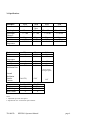
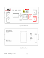
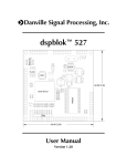
HPD 7401
LASER SOURCE
OPERATORS MANUAL
TN-0003D
HPD7401 Operators Manual
page 1
Table of Contents
HPD 7401............................................................................................................. 1
1.0
Introduction............................................................................................. 3
2.0
Laser Safety............................................................................................. 3
3.0
Specifications .......................................................................................... 4
4.0
Controls ................................................................................................... 5
4.1 Front Panel (Figure 4.0)............................................................................................5
4.2 Rear Panel (Figure 4.1) ..............................................................................................7
5.0
Operation................................................................................................. 8
5.1 Start up .......................................................................................................................8
5.2 Menus.........................................................................................................................9
5.2.1 Setup Menu .........................................................................................................9
5.2.2 Laser ON Display with Timer Enabled ...........................................................10
5.2.3 Laser ON Menu with Timer Disabled ..............................................................11
5.2.4 Aiming Beam ON menu with Timer Disabled ................................................12
6.0 Fiber Handling precautions ......................................................................... 13
7.0 Errors........................................................................................................... 14
8.0 Warranty...................................................................................................... 14
HPD 7401........................................................................................................... 15
TN-0003D
HPD7401 Operators Manual
page 2
1.0
2.0
Introduction
The HPD 7401 Laser source is designed to provide a simple and reliable source of
semiconductor laser diode light. It contains the laser diode (various power outputs and
wavelengths are available), a TEC controller to stabilize the laser temperature and a laser
driver to control the laser output power. All functions are controlled through a simple user
interface by a single board computer.
Laser Safety
This laser emits radiation that may cause harm to your eyes and/or skin. Proper laser eye safety
goggles should be used with this device. Exposure to the laser radiation should be avoided.
Access to this equipment should be limited to persons with appropriate training in laser safety
procedures. If there are any questions please contact the factory.
This instrument has not been registered as a medical device. It is intended to be used as a laser
source in a research environment. The user is responsible for any regulatory requirements for uses
other than this intended use.
Conforms to 21CFR1040. Made in North Brunswick, NJ 08902 U.S.A.
TN-0003D
HPD7401 Operators Manual
page 3
3.0 Specifications
Modules
Power
1
Wavelength
Wavelength
Tolerance
Fiber Diameter
Fiber NA
Laser
Temperature
System
Timer
Ambient
Temperature
Aiming Beam
Laser Current
External
Modulation Rate
5215
1.0 W Max
5325
2.0 W Max
5350
4.0 W Max
635 nm
+/- 3 nm
5230
2.0 W
Max
635 nm
+/- 3 nm
670 or 690 nm
+/- 10 nm
670 or 690 nm
+/- 10 nm
400 µm
0.22
10-20 ºC
600 µm
0.22
10-20 ºC
400 µm
0.22
15-30 ºC
600 µm
0.22
15-30 ºC
Min
0
0
Max
9999
35.0
Unit
Sec
ºC
0
0
DC
2.0
4.0
1.0
mW
A
KHz
(Sine, Square,
Triangle inputs)
External
Modulation
Transfer
Function
Size
Weight
Input Voltage 2
Input Current 2
(1A/0.5V)
5” x 18” x 16.5”
40
120
4
+ 2.0V
A/V
HxWxL
Lbs
VAC
A
Notes:
1. Adjustable up to max rated power.
2. Optional 220 Vac / 2A electrical input available.
TN-0003D
HPD7401 Operators Manual
page 4
4.0
Controls
4.1 Front Panel (Figure 4.0)
Power: Turns on power to the laser. This will turn on the control functions and the
TEC. The laser itself will remain off. When turning off the unit there is a 23 second delay while the system shuts down. Always make sure the laser is
off before shutting down the system. Wait at least 5 seconds before
restarting the system to insure proper startup.
Laser Enable (key switch): This is a safety interlock that must be in the on position
in order for the laser to function. Turning the interlock off will immediately
shut down the laser. This switch is in series with the rear panel interlock
connector.
LCD Display: This display shows a variety of user menus as well as system
information and error messages
Arrow buttons, Enter: These buttons are used to navigate through the menus and
adjust parameters (see section 5)
.
Aiming Beam button: Turns on the aiming beam. (The laser operated at reduced
power as set by I Aim in the setup menu). The Aiming Beam LED will
come on. The aiming beam will stay on until: a) the laser is turned on at full
power (LASER ON) or b) the aiming beam is turned off (STOP).
Laser On Button: Turns on the laser (at current set in the setup menu). The
LASER ON LED will come on. The laser will stay on for the number of
seconds indicated by the display if the timer is enabled or until the stop
button is pressed.
Stop Button: Turns off the laser. This will turn off either the laser or the aiming
beam depending on which one is operating.
Laser Aperture: SMA or FC bulkhead connector that connects to the laser source.
This aperture should be covered with the cap when the laser is not in use to
prevent damage to the fiber. Note: when attaching a fiber care should be
taken to prevent over tightening or rotating the fibers when they are in
contact. This may result in damage to the fiber and/or laser.
TN-0003D
HPD7401 Operators Manual
page 5
Figure 4.0 Front Panel Controls
Fig 4.1 Rear Panel Controls
TN-0003D
HPD7401 Operators Manual
page 6
4.2 Rear Panel (Figure 4.1)
Wavelength:
Power:
SN, Date:
Module, Module SN
Wavelength for this particular device
Rated output power when the laser is on.
Serial number, Date of manufacture for this 7401
Part number and SN for the laser contained within the
7401
Remote: 9- pin D connector that contains safety interlock and remote
operation functions. The remote operation pins are in parallel with the front
panel buttons and perform the same functions. To use the remote function,
connect a momentary switch between the desired pin and the GND pin.
Shorting the pin will operate the button. The interlock pins must be shorted
for the laser to operate. These may be connected to a remote safety
interlock.
Pin 1
Pin 2
Pin 3
Pin 4
Pin 5
Pin 6
Pin 7
Pin 8
Pin 9
Interlock
Interlock
Aiming Beam On
Laser On
Stop
GND
no connection
no connection
no connection
Line In Connector: AC cord connection
External Modulation Input (optional):
This input has limitations of DC to 1Khz maximum frequency input and 0 to
+2.25 maximum Voltage input. Care should be taken not to exceed these
limitations so that damage to the laser driver circuitry and/or the laser diode
itself can be avoided. The center pin of the BNC on the rear panel is the
positive (+) input. The input voltage amplitude controls the current setting
to the laser diode (0.5V / A).
TN-0003D
HPD7401 Operators Manual
page 7
5.0 Operation
5.1 Start up
Make sure proper laser safety precautions are in place. Place the unit on a stable
platform with clear access to the fan on the rear panel and the ventilation holes on
the bottom of the chassis.
Remove Cap from Fiber connector.
Attach an appropriate fiber pigtail.
Turn Key switch ON (1) and make sure remote interlock is shorted.
Verify that Laser Safety procedures have been adhered to.
Turn Power On.
A message indicating Software version, Laser Time and System Time will be
displayed for a few seconds
It will take a few minutes for the temperature of the laser to stabilize. During this
time the temperature will be shown ramping to the set point
TN-0003D
HPD7401 Operators Manual
page 8
5.2 Menus
5.2.1 Setup Menu
To enter the setup menu press Enter when the cursor is in column 1.
(1)
CURRENT
TEMP
TIMER
TIMER
I Aim
Ext Mod
Power
Power Mult.
(2)
1.00 A
25.1 C
9999 sec
ON/OFF
0.80 A
ON/OFF
1.000 W
1.00
Imax, Tmin, Tmax factory set depending on Laser module
Navigation
⇑⇓ with cursor in column 1: move between rows
⇑⇓ with cursor in column 2: adjust value of parameter. The change in value takes
effect immediately
⇔ move to adjacent column
<enter> move to column 1, When cursor is in column 1 move to LASER ON menu
TN-0003D
HPD7401 Operators Manual
page 9
5.2.2 Laser ON Display with Timer Enabled
(1)
9999
(2)
1.01
W
SEC
Notes: Power display with optional power measurement only
Press <enter> to return to setup menu
⇑⇓ adjust timer value when laser is off
All menu buttons are disabled when the laser is on.
When timer reaches zero the laser is turned off and the timer is reset.
TN-0003D
HPD7401 Operators Manual
page 10
5.2.3 Laser ON Menu with Timer Disabled
(1)
CURRENT:
TEMP:
POWER:
(2)
1.00A
25.1 C
0.00W
Notes: Power display with optional Power measurement only
“On” will be displayed when the laser is on.
Press <enter> when in column 1 to return to setup menu
Press <enter> in column 2 to return to column 1
⇑⇓ with cursor in column 1: move between rows
⇑⇓ with cursor in column 2: adjust value of parameter
⇔ move to adjacent column
Current and Temperature may be adjusted with laser on.
When the timer is off the laser will stay on until the stop button is pressed. Care
should be taken to ensure the laser is turned off after use.
Note: When Power Monitor Option is installed it can be turned on and off in
the main setup menu. To measure power out of a SMA connectorized fiber,
connect the clean fiber to the power monitor SMA bulkhead on the front
panel. For power measurements using a diffusive tip fiber, insert the clean
fiber into the power monitor porthole approximately 2.5 inches (to maximize
power measurement repeatability place fiber in same position each time used).
Care should be taken to keep all fibers and connectors clean when using power
monitor port. Replace dust cap on porthole when finished using power
monitor option.
TN-0003D
HPD7401 Operators Manual
page 11
External Modulation Option:
If this option has been installed a BNC connector will be located on the rear panel.
The main menu will also have a EXT MOD option that can be turned on and off.
This can be selected using normal menu commands shown previous to this section.
This input has limitations of DC to 1Khz maximum frequency input and 0 to +2.25
maximum Voltage input. Care should be taken not to exceed these limitations so
that damage to the laser driver circuitry and/or the laser diode itself can be avoided.
The center pin of the BNC on the rear panel is the positive input. The input voltage
amplitude controls the current setting to the laser diode (0.5V / A).
5.2.4 Aiming Beam ON menu with Timer Disabled
(1)
I Aim:
(2)
1.00A
Navigation:
⇑⇓ with cursor in column 2: adjust value of parameter
Current may be adjusted with laser on.
The laser will stay on until the stop button is pressed. Care should be taken to
ensure the laser is turned off after use. Pressing the stop button will return to the
laser on menu.
TN-0003D
HPD7401 Operators Manual
page 12
6.0 Fiber Handling precautions
A dirty or damaged fiber can cause reduction in output power or permanent damage
to the device. If you are not familiar with proper fiber handling procedures please
contact the factory for assistance. Good fiber handling procedures include:
• Keep fiber connector covered with the protective cap when not in use.
• Clean the fiber patch cord each time before it is inserted into the bulkhead
connector (see cleaning instructions below)
• Clean bulkhead connector as necessary (see cleaning instructions below)
• When using an SMA connector, make sure that the connector does not
rotate while it is being inserted into the bulkhead mount, this may cause
damage to the fiber.
To clean the ferrule end of a fiber
1) Apply isopropyl alcohol to a clean cotton swab
2) Clean the ferrule with the wet swab
3) Dry the ferrule with a clean dry swab
4) Blow across the ferrule with clean dry compressed air. Make sure no
cotton fibers remain.
5) Inspect the ferrule with a microscope or magnifying glass to make sure it
is clean
6) Immediately cover the ferrule with a protective cap or insert it into the
bulk head connector
To clean the front panel bulkhead
1) Blow dry nitrogen or clean dry compressed air into and around the
bulkhead opening. Immediately cover the bulkhead with a protective cap
or insert the cleaned ferrule end of the fiber into the bulkhead.
TN-0003D
HPD7401 Operators Manual
page 13
7.0 Errors
The following errors may be appear on the display
Interlock Open: This will occur when the laser enable switch is off (0) or when the
remote interlock is open. Turning on the switch or shorting the interlock pins should
eliminate this error.
TEC Error: This occurs when the TEC cannot cool the device to the appropriate
temperature. This may be caused by extremely high ambient temperatures or by an
obstruction to the fan. Turn the laser source off, let it cool down and make sure the
fan is not blocked and that the ambient temperature is normal. Turn the laser source
back on. If the problem persists contact HPD for instructions.
Other Errors: There are no other user serviceable errors. If other problems occur,
please make detailed notes about the type of problem and when the problem
occurred and contact the factory for instructions. There are no user serviceable parts
inside the laser source. DO NOT OPEN the laser enclosure.
8.0 Warranty
HPD's commitment to quality and reliability assures the 7401 and the laser module
it contains are completely characterized prior to shipment to the customer.
HPD unconditionally warranties the 7401 to be free of defects in material and
workmanship and to operate as specified for a period of 1 year or 1000 hrs (as
measured by the internal clock) whichever comes first. HPD's liability is strictly
limited to replacing/repairing the 7401.
HPD is not responsible for damage caused by the customer including improper fiber
handling.
TN-0003D
HPD7401 Operators Manual
page 14
HPD 7401
LASER SOURCE
OPERATORS MANUAL
H
P
D
7
4
0
1
TN-0003D
HPD7401 Operators Manual
page 16
TITLE
HPD7401 OPERATORS MANUAL
SUBJECT
HPD7401 OPERATORS MANUAL
DOC # TN-0003
Issue 5/27/2004
Date
Signature
Signature
REV D
Effective Date
Author
Approval
5/27/2004
J. RIORDAN
D. BAMBRICK
5/27/2004 11:35 AM
REVISIONS
Rev
A
B
C
D
Date
11/5/02
2/26/04
4/29/04
5/27/04
TN-0003D
Changes made
Original (Production Version)
Add fiber handling precautions, update specs, warranty
Add Power Monitor operation instructions
Add External Modulation Option Description/Parameters
HPD7401 Operators Manual
By
JFR
JFR
DB
DB
page 17