1
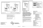
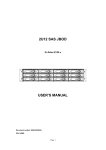
COMMAND AND CONTROL STYLES
212i INDOOR STYLE
•
Flushmount, indoor design
212w WEATHER RESISTANT STYLE
•
Flushmount, outdoor design
212r RUGGEDIZED STYLE
•
Weatherproof self-contained metal housing
•
Vandal resistant
•
Cast metal housing suitable for wall, post or gooseneck
mounting
•
Available in white or black
•
4 On-Board relays
212se SEALED ENVIRONMENTAL STYLE
•
Weatherproof self-contained metal housing
•
•
Vandal resistant
Small design suitable for residential, commercial and industrial
applications
•
4 On-Board Relays
•
Available in Bronze or Satin Aluminum
212mp MULTIPAD BACKLIT STYLE
•
Weatherproof self-contained housing.
•
Illuminated Keys
•
Contemporary Design
•
4 On-board Relays
DOOR♦GARD
TM
FEATURES AND PROGRAMMING GUIDE
COMMAND AND CONTROL SERIES
DOOR♦GARD COMMAND AND CONTROL SERIES keypads offer field proven reliability and cost effective
solutions anywhere limited control or access is desired. Designed for individual control of up to four devices, Door♦Gard
Command and Control Series keypads are the perfect choice for controlling electric locking devices, security systems,
automatic operators or machinery. Door♦Gard keypads accept power from a 12 or 24 Volt AC/DC supply.
ACCESSORIES
DATA LOGGING
•
IEI-250 PRINTER INTERFACE provides power,
communication inputs and outputs for up to 8 Door♦Gard
keypads. Interfaces with any parallel printer for user/door
activity logging
INSTALLATION
•
IEI-280 WEATHERPROOF SURFACE BACK BOX
•
IEI-281 FLUSH MOUNT BACK BOX
•
IEI 12 or 24 VDC 1A PLUG-IN POWER SUPPLIES
•
IEI-293 THREE RELAY PLUG--IN BOARD with FORM C,
1 Amp relays. Converts transistor outputs to dry contacts
(for use with Command and Control indoor, weather
resistant and Mullion styles).
TAMPER PROTECTION
•
IEI-282 TAMPER SWITCH detects faceplate removal
•
IEI-283 SECURITY MODULE responds to tamper switch
(included) and cuts all in/out power to the door lock. Wires
can’t be crossed to unlock door. Must be reset from inside the
protected area.
•
IEI-289 TAMPER SCREWS - TRI-HEAD
•
IEI-267 1/4” DRIVER
•
IEI-270 ADAPTER SOCKET - TRI-HEAD
•
IEI-271 TAMPER WRENCH - ALLEN WITH PIN
• IEI-288 TAMPER SCREWS - ALLEN WITH PIN
OTHER DOOR♦GARD PRODUCTS FROM IEI
CONTROL PANEL ACCESS CONTROL SYSTEMS
240
Battery Operated Keypad-Direct
keyswitch replacement (for indoor use)
262B
The Partitioner Self-Contained 2-zone control
POWERGARD POWER SUPPLIES
PG1224-1 12/24VDC 1.3 Amp Power Supply
PG1224-3 12/24VDC 2.5 Amp Power Supply
Monday-Friday 8:00 A.M. – 7:00 P.M. EST. We understand your time is valuable and we know that calling our Technical Support Department will
ensure that you’ll make the most profit possible with your IEI product. Thank you for your purchase. We appreciate your business.
International Electronics, Inc. (IEI) warrents its products to be free from defects in material and workmanship when they have been installed in
accordance with the manufacturer’s instructions and have not been modified or tampered with. IEI does not assume any responsibility for damage or
injury to person or property due to improper care, storage, handling, abuse, misuse, normal wear and tear or an act of God.
IEI’s sole responsibility is limited to the repair (at IEI’s option), the replacement of the defective product or part when sent to IEI’s facility (freight and
insurance charges prepaid), after obtaining IEI’s Return Merchandise Authorization. IEI will not be liable to the purchaser or any one else for incidental
or consequential damages arising from any defect in, or malfunction of, it’s products.
This warranty shall expire two years after shipping date. Except as stated above, IEI makes nor warranties, either expressed or implied, as to any
matter whatsoever, including, without limitation to, the condition of its products, their merchantability, or fitness for any particular reason.
International Electronics, Inc.
427 Turnpike St, Canton, MA 02021 U.S.A.
800-343-9502, 781-821-5566, 781-821-4443 (FAX)
Fax Information Center 781-821-0734 (From Your FAX machine)
4
•
•
•
•
•
•
•
REMOTE TRIGGERING INPUT (REX)
By default, upon a momentary closure this normally
open loop triggers the main relay for the same time
period as the Master Code. You can also program the
REX to operate any combination of the available
outputs. The auxiliary outputs activate for their
programmed time.
4 INDEPENENT OUTPUTS
4 INDEPENENT TIMERS
ALL OUTPUTS ASSIGNABLE BY CODE
ON BOARD MAIN RELAY
120 USERS
REMOTE TRIGGERING INPUT
KEYPAD PROGRAMMABLE
KEYPRESS FEEDBACK/AUDIBLE KEYPRESS
Door♦Gard Command and Control keypads, by default,
acknowledge a keypress by momentarily illuminating the
yellow LED or activate the sounder. This depends on
the model. You can turn this off through programming.
MEMORY
Non-volatile EEPROM memory means your codes and
instructions will be there whether you remove power for
5 minutes or 5 years.
PROGRAMMING
All programming is done entirely from the front of the
keypad. LED or sounder guidance makes programming
easy. It takes seconds for an authorized user to change
codes.
SELF-CONTAINED ACCESS CONTROL SYSTEMS
FEATURES
232i
Indoor Keypad
•
Propped Door Alarm Relay
•
Lock Release Relay
232w
Weather-Resistant Keypad
•
Timed Egress Input
•
Lock Release Time
232se Sealed Environment Keypad
•
Forced Door Alarm Relay
•
Alarm Zone Shunting
232r
Ruggedized Keypad
Relay
•
Front Programmable
232iLM Mullion Keypad
•
Multiple User
233
Card Reader System
234
Card Reader/Keypad System
If this product does not seem to operate properly, please call our Technical Support Department toll free at 1-800-343-9502 (or 781-821-5566)
6050212 Rev. 1.3
FEATURES:
www.ieib.com
KEYPAD ACTIVE OUTPUT
Door♦Gard Command and Control keypads can be
programmed to energize a voltage output whenever a
key is touched. You can use this to turn on lights, CCTV
camera, or notify a guard. This output is not available if
you are using the IEI 250 Printer Interface.
CODES
The Door♦Gard Command and Control keypads allow
up to 120 individual user codes. Codes can be 1 to 6
digits in length and digits may be repeated. The Master
Code is always stored in user location one (1).
AUTO ENTRY
This feature is used when you don’t want to press the *
key after entering your code. You only need to enter
your code number (without pressing *) and the relay
activates. To use this feature, the user codes must be
the same length as the master code. Please remember
to access program mode when auto entry is on, do not
press the * key (Press: 99 # master code), however the *
is required while entering programming commands.
MAIN RELAY
The main relay is a form C relay, which you can program
as a timed output (1 to 90 seconds) or to toggle (latch).
See the Wiring Diagram and Specifications for the relay
electrical specifications.
AUXILIARY OUTPUTS
You can program these outputs as timed outputs (1 to
90 seconds) or to toggle (latch). They can be controlled
individually or in combination by a code. Some models
have 1 Amp form C relays and other models have
negative voltage outputs with a 50mA sink.*
AUDIT TRAIL
Using the 250 Printer Interface (not included), you can
get an accurate real-time audit trail. Up to 8 keypads can
be monitored simultaneously. The 250 comes with a
power supply and a printer cable and it easily connects
to any parallel printer. This output is not available on all
models.
PANIC
Panic is activated by pressing the * and # keys at the
same time. By default, it operates output 4 and activates
for 1 second.
*Voltage Outputs may be converted to 1 Amp, FormC relays by adding the 293 Auxiliary Relay Board
(Model # 0219000).
6050212 Rev. 1.3
1
www.ieib.com
1
2
TESTING THE KEYPAD
3
PROGRAMMING
1. Connect the positive (+) lead of your power supply to
the terminal strip (TS1) V+ input.
1. Enter programming mode
Press 99 # (master code) *
2. Connect the negative (-) lead of your power supply to
the terminal strip (TS1) V- input.
PROGRAMMING OPTIONS CHART
1
Indicator
Flash/Beep Slowly
2
If the pre-programmed default values must be changed or additional functions are desired, the following options may
be programmed.
1. Enter programming mode
2. To Change master code
Press 1 # (new master code) *
Flash/Beep Fast
Press (new master code) *
Flash/Beep Slowly
If you must change the Main Relay
time, see option 2 on the
Programming Options chart.
2. Change master code/set main relay time1
3. To Add/change second code
Press 2 # (new user code) *
Press (new user code) *
Press
99 # (master code) *
Press
(time) # 1 # (new code) * (new code) *
Press
10 # 1 # 4321 * 4321 *
3. Add/change user code
Press
(user number) # (new code) * (new code) *
4. Add/change user code to toggle main relay1
Press
(00) # (user number) # (new code) * (new code) *
5. Delete user codes
Press
(user number) # * *
6. Set output 2 time1
Press
12 # (Relay Time) # 0 # **
7. Set output 3 time1
Press
13 # (Relay Time) # 0 # **
8. Set output 4 time1
Press
14 # (Relay Time) # 0 # **
9. Set outputs for Remote Triggering Input
Press
17 # (outputs: 1, 2, 3 and/or 4) # 0 # **
10. Set outputs for Panic
Press
18 # (outputs: 1, 2, 3 and/or 4) # 0 # **
11. Turn keypress feedback/audible keypress on
Press
30 # 0 # 1 # * *
NOTES:
• Door♦Gard Command and Control keypads are factory
programmed with a master code of 1234.
12. Turn keypress feedback/audible keypress off
Press
30 # 0 # 0 # * *
13. Turn yellow LED/sounder on with relay
Press
30 # 1 # 1 # * *
•
14. Turn yellow LED/sounder off with relay
Press
30 # 1 # 0 # * *
COMMAND AND CONTROL
DEFAULTS
Indicator refers to either the yellow LED or
sounder.
15. Turn auto entry on
Press
30 # 2 # 1 # * *
•
2
Door♦Gard Command and Control keypads are
designed for easy installation in a minimum amount of
time. The following default settings are factory
programmed:
16. Turn auto entry off
Press
30 # 2 # 0 # * *
•
The master code allows access to programming mode
and activates the main relay.
17. Turn keypad active on2
Press
43 # 0 # 99 # * *
18. Turn keypad active off
Press
43 # 0 # 00 # * *
•
By default (auto-entry is off), all codes must be followed
by the * key.
19. Erase keypad memory/reset defaults
Press
46 # 00000 # 00000 # * *
•
Codes may be from 1-6 digits in length, and digits
may be repeated.
20. Energize selected output(s) with a user code 3
Press
59 # (outputs 1, 2, 3 and/or 4) # user location # (new
code) * (new code) *
Press
*
3. Turn on your power supply.
4. Press 7890#123456 *. If all 12 keypresses are
verified, the keypad enters self-test mode.
The yellow LED flashes/sounder beeps 3 times, then
turns on solid for 3 seconds.
Note: Self-test mode can be used to troubleshoot a
keypad in the field. If you do not get the continuous
light, the memory has been corrupted and should be
re-programmed with the default command (see
option #19).
4. To Add/change third code
Press 3 # (new user code) *
Press (new user code) *
Flash/Beep Fast
Flash/Beep Slowly
5. Up to 120 codes may be added
in this fashion
5. Enter the master code (default = 1234) followed by
the * key and the relay energizes. Refer to
programming section to program your keypad.
6. Exit programming mode
Press *
NOTE:
You can program your keypad in your shop or at the
installation site. Programmed information is stored in
non-volatile memory so it won’t be lost if power is
removed.
Master Code (user 1):
Main Relay Time:
Auxiliary Output Time:
Panic Output:
Keypad Active Output:
REX Triggers:
Keypress Feedback:
LED – Normal State
LED - Relay Energized
Auto-Entry
Flash/Beep Fast
Flash/Beep Slowly
1234
5 seconds
5 seconds
Output 4
Off
Main Relay
On
Red
Green
Off
•
If you must change the default settings or additional
functions are desired, please refer to the Programming
Options Chart after you are familiar with the
Programming section.
•
Off
1
The master code is always stored in user location
1.
Example: Master code of 4321/relay time of 10 seconds
Example: User 2; code 4321; energize outputs 2 & 3
21. Exit programming mode
Press
59 # 23 # 2 # 4321 * 4321*
If you forgot the master code or it is not working,
momentarily push SW1, (see wiring diagram for
location) to enter programming mode and go to option
#19 on the Programming Options chart to default
keypad.
NOTES:
If the yellow LED lights solid or sounder is on steady
while in programming mode, an error has occurred.
Press * to clear (yellow LED should start flashing) and
start over from step 2 or 3 above.
2. Keypad active is a negative voltage output (sink) available on terminal (or wire) marked WB (see wiring diagrams for
location).
1. Relay times must always be represented by 2 digits. Example: 5 seconds = 05. Latching /toggle is accomplished by
entering a time of 00.
3. This feature does not work with the master code.
6050212 Rev. 1.3
2
www.ieib.com
6050212 Rev. 1.3
3
www.ieib.com