1
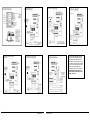
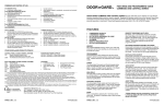
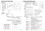
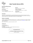
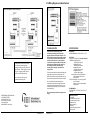
212i Wiring Diagrams and Specifications
The diagram above shows how to connect
two keypads to control a single door.
Entering your code on keypad 2 unlocks the
maglock directly. When you enter your code
on keypad 1, it triggers the REX input of
keypad two, which unlocks the door
TECHNICAL NOTES
SPECIFICATIONS:
This product was re-designed using a new
manufacturing technology, which changed the
physical appearance of the keypad electronics. The
LED’s changed to surface mount chip LED’s mounted
on bottom of the circuit board which eliminates the
need for the wire harnesses. It is also possible to
control the red and green chip LED’s externally, with
an alarm panel for example, by using connector J1.
See the diagram for details. Also, the voltage
selection jumper on the main circuit board is no
longer required.
MECHANICAL:
BOARD DIMENSIONS: 1.80”W x 2.845”H x 1.125”D
To prevent electrical kick back voltage from damaging the
keypad, when using an electrical locking device, you
MUST install the transorb as close as possible to the lock.
Wire the transorb in parallel with the lock power terminals.
Please note that user codes must be
programmed into both keypads
Also, to avoid ESD (electro-static discharge) from
interfering with the operation of the keypad, ground the
negative terminal of the keypad to earth ground. If you
cannot ground the power supply, then you must ground
the keypad housing.
IEI recommends using a filtered and regulated power
supply
INTERNATIONAL ELECTRONICS, INC.
427 TURNPIKE STREET
CANTON, MA 02021 USA
800-343-9502, 781-821-5566,
781-821-4443 (FAX)
WEB ADDRESS: www.ieib.com
4
ELECTRICAL:
VOLTAGE: 12-24 Volts AC/DC (No Jumper Required)
CURRENT: 8mA@12VDC typical;
35ma with relay energized.
16mA@24VDC typical;
45ma with relay energized.
21mA@12VAC typical;
74mA with relay energized.
43mA@24VAC typical;
91mA with relay energized.
Note: Keypads using the 293 Relay Board,
need an additional 30mA for each
relay energized.
OUTPUTS: Main Relay: 5 Amp, Form C @ 24VDC
with 10 Amp surge.
Outputs 2, 3, and 4 are 50mA negative
voltage outputs
ENVIRONMENTAL:
TEMPERATURE: -20°F TO 130°F (-28°C TO 54°C)
Indoor Only
Packing Checklist
212i Keypad
10 Conductor Wire Harness (1)
4 Conductor Wire Harness (1)
Slotted screws (2)
Security Screws (2)
Transorb (1)
Features & Programming Guide
Warranty Guide
6040400 Rev 1.2
6040400 Rev 1.2
1
To control the LED’s externally cut the four
traces in the box underneath connector J1.
Before connecting the alarm panel’s LED
control lines to J1 verify the traces are cut. To
verify, measure continuity between the end of
the wire on the wire harness and the square
pad on the circuit board below the box
corresponding to the wire you’re measuring.
Permanent damage to the keypad may
result if voltage is connected to J1 when
the traces are not cut.
2
6040400 Rev 1.2
6040400 Rev 1.2
3